F 500 - Heating Jøtul - Free user manual and instructions
Find the device manual for free F 500 Jøtul in PDF.
| Product type | Wood stove |
| Brand | Jøtul |
| Model | F 500 |
| Material | Cast iron |
| Surface treatment | Black paint and enamel |
| Fuel | Wood only |
| Nominal heat output | 8,5 kW |
| Efficiency | 78% |
| Weight | 200 kg |
| Maximum log length | 55 cm |
| Flue connection diameter | ∅150 mm |
| Recommended draft | 10 Pa |
| Flue gas temperature | 285 °C |
| CO rate (at 13% O₂) | 0.10 % |
| Air inlets | Upper and lower |
| Operating mode | Intermittent (batch combustion) |
| Hourly wood consumption (nominal) | Approximately 2.7 kg/h |
| Flue gas mass flow | 8.0 g/s |
| Floor protection | Integrated heat shield, minimum metal plate 0.9 mm |
| Optional equipment | External ventilation duct (ref. 221031), rear heat shield (ref. 350956) |
| Periodic maintenance | Replacement of deflector, lining plates, and refractory bricks |
| Spare parts | Use only genuine Jøtul parts |
| Serial number | Referenced on product label, to be mentioned when contacting |
Frequently Asked Questions - F 500 Jøtul
User questions about F 500 Jøtul
0 question about this device. Answer the ones you know or ask your own.
Ask a new question about this device
Download the instructions for your Heating in PDF format for free! Find your manual F 500 - Jøtul and take your electronic device back in hand. On this page are published all the documents necessary for the use of your device. F 500 by Jøtul.
USER MANUAL F 500 Jøtul
GB - Installation manual with technical data 11
natural_image
Exterior view of a vintage wood-paneled gas stove with arched windows and flames (no text or symbols visible)
text_image
Jetul produkter/ Jetul's products MAYLLE - canadatihur- og kreditinjärkem 12 - jetuläkem (kreding, 100 mmol/mol) - canadat 13 - kreditinjärkem (kreding, 100 mmol/mol) 14 - kreditinjärkem (kreding, 100 mmol/mol) 15 - kreditinjärkem (kreding, 100 mmol/mol) 16 - kreditinjärkem (kreding, 100 mmol/mol) 17 - kreditinjärkem (kreding, 100 mmol/mol) 18 - kreditinjärkem (kreding, 100 mmol/mol) 19 - kreditinjärkem (kreding, 100 mmol/mol) 20 - kreditinjärkem (kreding, 100 mmol/mol) 21 - kreditinjärkem (kreding, 100 mmol/mol) 22 - kreditinjärkem (kreding, 100 mmol/mol) 23 - kreditinjärkem (kreding, 100 mmol/mol) 24 - kreditinjärkem (kreding, 100 mmol/mol) 25 - kreditinjärkem (kreding, 100 mmol/mol) 26 - kreditinjärkem (kreding, 100 mmol/mol) 27 - kreditinjärkem (kreding, 100 mmol/mol) 28 - kreditinjärkem (kreding, 100 mmol/mol) 29 - kreditinjärkem (kreding, 100 mmol/mol) 30 - kreditinjärkem (kreding, 100 mmol/mol) 31 - kreditinjärkem (kreding, 100 mmol/mol) 32 - kreditinjärkem (kreding, 100 mmol/mol) 33 - kreditinjärkem (kreding, 100 mmol/mol) 34 - kreditinjärkem (kreding, 100 mmol/mol) 35 - kreditinjärkem (kreding, 100 mmol/mol) 36 - kreditinjärkem (kreding, 100 mmol/mol) 37 - kreditinjärkem (kreding, 100 mmol/mol) 38 - kreditinjärkem (kreding, 100 mmol/mol) 39 - kreditinjärkem (kreding, 100 mmol/mol) 40 - kreditinjärkem (kreding, 100 mmol/mol) 41 - kreditinjärkem (kreding, 100 mmol/mol) 42 - kreditinjärkem (kreding, 100 mmol/mol) 43 - kreditinjärkem (kreding, 100 mmol/mol) 44 - kreditinjärkem (kreding, 100 mmol/mol) 45 - kreditinjärkem (kreding, 100 mmol/mol) 46 - kreditinjärkem (kreding, 100 mmol/mol) 47 - kreditinjärkem (kreding, 100 mmol/mol) 48 - kreditinjärkem (kreding, 100 mmol/mol) 49 - kreditinjärkem (kreding, 100 mmol/mol) 50 - kreditinjärkem (kreding, 100 mmol/mol) 51 - kreditinjärkem (kreding, 100 mmol/mol) 52 - kreditinjärkem (kreding, 100 mmol/mol) 53 - kreditinjärkem (kreding, 100 mmol/mol) 54 - kreditinjärkem (kreding, 100 mmol/mol) 55 - kreditinjärkem (kreding, 100 mmol/mol) 56 - kreditinjärkem (kreding, 100 mmol/mol) 57 - kreditinjärkem (kreding, 100 mmol/mol) 58 - kreditinjärkem (kreding, 100 mmol/mol) 59 - kreditinjärkem (kreding, 100 mmol/mol) 60 - kreditinjärkem (kreding, 100 mmol/mol) 61 - kreditinjärkem (kreding, 100 mmol/mol) 62 - kreditinjärkem (kreding, 100 mmol/mol) 63 - kreditinjärkem (kreding, 100 mmol/mol) 64 - kreditinjärkem (kreding, 100 mmol/mol) 65 - kreditinjärkem (kreding, 100 mmol/mol) 66 - kreditinjärkem (kreding, 100 mmol/mol) 67 - kreditinjärkem (kreding, 100 mmol/mol) 68 - kreditinjärkem (kreding, 100 mmol/mol) 69 - kreditinjärkem (kreding, 100 mmol/mol) 70 - kreditinjärkem (kreding, 100 mmol/mol) 71 - kreditinjärkem (kreding, 100 mmol/mol) 72 - kreditinjärkem (kreding, 100 mmol/mol) 73 - kreditinjärkem (kreding, 100 mmol/mol) 74 - kreditinjärkem (kreding, 100 mmol/mol) 75 - kreditinjärkem (kreding, 100 mmol/mol) 76 - kreditinjärkem (kreding, 100 mmol/mol) 77 - kreditinjärkem (kreding, 100 mmol/mol) 78 - kreditinjärkem (kreding, 100 mmol/mol) 79 - kreditinjärkem (kreding, 100 mmol/mol) 80 - kreditinjärkem (kreding, 100 mmol/mol) 81 - kreditinjärkem (kreding, 100 mmol/mol) 82 - kreditinjärkem (kreding, 100 mmol/mol) 83 - kreditinjärkem (kreding, 100 mmol/mol) 84 - kreditinjärkem (kreding, 100 mmol/mol) 85 - kreditinjärkem (kreding, 100 mmol/mol) 86 - kreditinjärkem (kreding, 100 mmol/mol) 87 - kreditinjärkem (kreding, 100 mmol/mol) 88 - kreditinjärkem (kreding, 100 mmol/mol) 89 - kreditinjärkem (kreding, 100 mmol/mol) 90 - kreditinjärkem (kreding, 100 mmol/mol) 91 - kreditinjärkem (kreding, 100 mmol/mol) 92 - kreditinjärkem (kreding, 100 mmol/mol) 93 - kreditinjärkem (kreding, 100 mmol/mol) 94 - kreditinjärkem (kreding, 100 mmol/mol) 95 - kreditinjärkem (kreding, 100 mmol/mol) 96 - kreditinjärkem (kreding, 100 mmol/mol) 97 - kreditinjärkem (kreding, 100 mmol/mol) 98 - kreditinjärkem (kreding, 100 mmol/mol) 99 - kreditinjärkem (kreding, 100 mmol/mol) 100 - kreditinjärke * KREDIT INJALO PRODUKTEN * KREDIT INJALO PRODUKTEN * KREDIT INJALO PRODUKTEN * KREDIT INJALO PRODUKTEN * KREDIT INJALO PRODUKTEN * KREDIT INJALO PRODUKTEN * KREDIT INJALO PRODUKTEN * KREDIT INJALO PRODUKTEN * KREDIT INJALO PRODUKTEN * KEDUT * KEDUT * KEDUT * KEDUT * KEDUT * KEDUT * KEDUT * KEDUT * KEDUT * KEDUT * KEDUT * KEDUT * KEDUT * KEDUT * KEDUT * KEDUT * KEDUT * KEDUT * KEDUT * KEDUT * KEDUUT * KEDUT * KEDUT * KEDUT * KEDUT * KEDUT * KEDUT * KEDUT * KEDUT * KEDUT * KEDUT * KEDUT * KEDUT * KEDUT * KEDUT * KEDUT * KEDUT * KEDUT * KEDUT * KEDUT * KESUT * KESUT * KESUT * KESUT * KESUT * KESUT * KESUT * KESUT * KESUT * KESUT * KESUT * KESUT * KESUT * KESUT * KESUT * KESUT * KESUT * KESUT * KESUT KESUTGB - Before use, please read "General use and maintenance manual" carefully.
text_image
Fiatum Jedal Tazem tatalie (notional) local Standard Citation in accordance to applicable standards table. Worner, M. 1962, 1984, 1985, 1986, 1987, 1988, 1989, 1990, 1991, 1992, 1993, 1994, 1995, 1996, 1997, 1998, 1999, 2000, 2001, 2002, 2003, 2004, 2005, 2006, 2007, 2008, 2009, 2010, 2011, 2012, 2013, 2014, 2015, 2016, 2017, 2018, 2019, 2020, 2021, 2022, 2023, 2024, 2025, 2026, 2027, 2028, 2029, 2030, 2031, 2032, 2033, 2034, 2035, 2036, 2037, 2038, 2039, 2040, 2041, 2042, 2043, 2044, 2045, 2046, 2047, 2048, 2049, 2050, 2051, 2052, 2053, 2054, 2055, 2056, 2057, 2058, 2059, 2060, 2061, 2062, 2063, 2064, 2065, 2066, 2067, 2068, 2069, 2070, 2071, 2072, 2073, 2074, 2075, 2076, 2077, 2078, 2079, 2080, 2081, 2082, 2083, 2084, 2085, 2086, 2087, 2088, 2089, 2090, 2091, 2092, 2093, 2094, 2095, 2096, 2097, 2098, 2099, 2100, 2101, 2102, 2103, 2104, 2105, 2106, 2107, 2108, 2109, 2110, 2111, 2112, 2113, 2114, 2115, 2116, 2117, 2118, 2119, 2120, 2121, 2122, 2123, 2124, 2125, 2126, 2127, 2128, 2129, 2130, 2131, 2132, 2133, 2134, 2135, 2136, 2137, 2138, 2139, 2140, 2141, 2142, 2143, 2144, 2145, 2146, 2147, 2148, 2149, 2150, Specialty: Qualification: Con-ficial boundaries: Approved by: Macyo: Standard Santel: M.A. x- Specialty: M.A. x- Normality: M.A. x- Normality: M.A. x- Normality: M.A. x- Normality: M.A. x- Normality: M.A. x- Normality: M.A. x- Normality: M.A. x- Normality: M.A. x- Normality: M.A. x- Normality: M.A. x- Normality: M.A. x- Normality: M.A. x- Normality: M.A . x- Normality: M.A. x- Normality: M.A. x- Normality: M.A. x- Normality: M.A. x- Normality: M.A. x- Normality: M.A. x- Normality: M.A. x- Normality: M.A. x- Normality: M.A. x- Normality: M.A. x- Normality: M.A. x- Normality: M.A. x- Normalty: M.A. x- Normality: M.A. x- Normality: M.A. x- Normality: M.A. x- Normality: M.A. x- Normality: M.A. x- Normality: M.A. x- Normality: M.A. x- Normality: M.A. x- Normality: M.A. x- Normality: M.A. x- Normality: M.A. x- Normality: M.C. x- Normality: M.A. x- Normality: M.A. x- Normality: M.A. x- Normality: M.A. x- Normality: M.A. x- Normality: M.A. x- Normality: M.A. x- Normality: M.A. x- Normality: M.A. x- Normality: M.A. x- Normality: M.A. x- Normality: M.A. x- Neutrality: x- Normality: x- Normality: x- Normality: x- Normality: x- Normality: x- Normality: x- Normality: x- Normality: x- Normality: x- Normality: x- Normality: x- Normality: x- Normality: x- Normality: x- Normality: x- Normality: x- Normality: x- Normality: x- Normality: x- Normality: x- Neutrality: x- Neutrality: x- Neutrality: x- Neutrality: x- Neutrality: x- Neutrality: x- Neutrality: x- Neutrality: x- Neutrality: x- Neutrality: x- Neutrality: x- Neutrality: x- Neutrality: x- Neutrality: x- Neutrality: x- Neutrality: x- Neutrality: x- Neutrality: x- Neutrality: x- Neutrality: x- Normality: x- Normality: x- Normality: x- Normality: x- Normality: x- Normality: x- Normality: x- Normality: x- Normality: x- Normality: x- Normality: x- Normality: x- Normality: x- Normality: x- Normality: x- Normality: x- Normality: x- Normality: x- Normality: x- normalty normalty normalty normalty normalty normalty normalty normalty normalty normalty normalty normalty normalty normalty normalty normalty normalty normalty normalty normalty normalty normalty normalty normalty normalty normalty normalty normalty normalty normalty normalty normalty normalty normalty naturalty naturalty naturalty naturalty naturalty naturalty naturalty naturalty naturalty naturalty naturalty naturalty naturalty naturalty naturalty naturalty naturalty naturalty naturalty naturalty naturalty naturalty naturalty naturalty naturalty naturalty naturalty naturalty naturalty naturalty naturalty naturalty naturalty naturalt y. Year. Dec. (Year). Dec. (Year). Normalities: Normalities: Normalities: Normalities: Normalities: Normalities: Normalities: Normalities: Normalities: Normalities: Normalities: Normalities: Normalities: Normalities: Normalities: Normalities: Normalities: Normalities: Normalities: Normalities: Normalities: Normalities: Normalities: Normalities: Normalities: Normalities: Normalities: Normalities: Normalities: Normalities: Normalities: Normalities: Normalities: Normalities: Total number of employees in the company's capital : Total number of employees in the company's capital : Total number of employees in the company's capital : Total number of employees in the company's capital : Total number of employees in the company's capital : Total number of employees in the company's capital : Total number of employees in the company's capital : Total number of employees in the company's capital : Total number of employees in the company's capital : Total number of employees in the company's capital : Total number of employees in the company's capital : Total number of employees in the company's capital : Total number of employees in the company's capital : Total number of employees in the company's capital : Total number of employees in the company's capital : Total number of employees in the company's capital : Total number of employees in the company's capital : Total number of employees in the company's capital : Total number of employees in the company's capital : Total number of employees in the company's capital : Total number of employees in the company's capital :\nTotal number of employees in the company's capital : Total number of employees in the company's capital : Total number of employees in the company's capital : Total number of employees in the company's capital : Total number of employees in the company's capital : Total number of employees in the company's capital : Total number of employees in the company's capital : Total number of employees in the company's capital : Total number of employees in the company's capital : Total number of employees in the company's capital Total number of employees in the company's capital : Total number of employees in the company's capital : Total number of employees in the company's capital : Total number of employees in the company's capital : Total number of employees in the company's capital : Total number of employees in the company's capital : Total number of employees in the company's capital : Total number of employees in the company's capital : Total number of employees in the company's capital : Total number of employees in the company's total : Total number of employees in the company's total : Total number of employees in the company's total : Total number of employees in the company's total : Total number of employees in the company's total : Total number of employees in the company's total : Total number of employees in the company's total : Total number of employees in the company's total : Total number of employees in the company's total : Total number of employees in the company's total : Total number of employees in the company's annual : Total number of employees in the company's annual : Total number of employees in the company's annual : Total number of employees in the company's annual : Total number of employees in the company's annual : Total number of employees in the company's annual : Total number of employees in the company's annual : Total number of employees in the company's annual : Total number of employees in the company's annual : Total number of employees in the company's annual : Total number of employees in the company's year : Total number of employees in the company's year : Total number of employees in the company's year : Total number of employees in the company's year : Total number of employees in the company's year : Total number of employees in the company's year : Total number of employees in the company's year : Total number of employees in the company's year : Total number of employees in the company's year : Total number of employees in the company's year : Total number of employees in the company's annual : Total number of employees in the company's annual : Total number of employees in the company's annual : Total number of employees in the company's annual : Total number of employees in the company's annual : Total number of employees in the company's annual : Total number of employees in the company's annual : Total number of employees in the company's annual : Total number of employees in the company's annual : Total number of employees in the company's annually : Total number of employees in the company's annual : Total number of employees in the company's annual : Total number of employees in the company's annual : Total number of employees in the company's annual : Total number of employees in the company's annual : Total number of employees in the company's annual : Total number of employees in the company's annual : Total number of employees in the company's annual : Total number of employees in the company's annual : Total number of employees in the company's total : Total number of employees in the company's total : Total number of employees in the company's total : Total number of employees in the company's total : Total number of employees in the company's total : Total number of employees in the company's total : Total number of employees in the company's total : Total number of employees in the company's total : Total number of employees in the company's total : Total number of employees in the company's full : Total number of employees in the company's full : Total number of employees in the company's full : Total number of employees in the company's full : Total number of employees in the company's full : Total number of employees in the company's full : Total number of employees in the company's full : Total number of employees in the company's full : Total number of employees in the company's full : Total number of workers : Total number of workers : Total number of workers : Total number of workers : Total number of workers : Total number of workers : Total number of workers : Total number of workers : Total number of workers : Total number of workers : Total number of workers : Total number of workers : Total number of workers : Total number of workers : Total number of workers : Total number of workers : Total number of workers : Total numbers : Total numbers : Total numbers : Total numbers : Total numbers : Total numbers : Total numbers : Total numbers : Total numbers : Total numbers : Total numbers : Total numbers : Total numbers : Total numbers : Total numbers : Total numbers : Total numbers : Total numbers : Total numbers : Total numbers : Tonal numbers : Tonal numbers : Tonal numbers : Tonal numbers : Tonal numbers : Tonal numbers : Tonal numbers : Tonal numbers : Tonal numbers : Tonal numbers : Tonal numbers : Tonal numbers : Tonal numbers : Tonal numbers : Tonal numbers : Tonal numbers : Tonal numbers : Tonal numbers : Tonal numbers : Tonal numbers : Toral numbers : Toral numbers : Toral numbers : Toral numbers : Toral numbers : Toral numbers : Toral numbers : Toral numbers : Toral numbers : Toral numbers : Toral numbers : Toral numbers : Toral numbers : Toral numbers : Toral numbers : Toral numbers : Toral numbers : Toral numbers : Toral numbers : Toral numbers : Tocal numbers : Tocal numbers : Tocal numbers : Tocal numbers : Tocal numbers : Tocal numbers : Tocal numbers : Tocal numbers : Tocal numbers : Tocal numbers : Tocal numbers : Tocal numbers : Tocal numbers : Tocal numbers : Tocal numbers : Tocal numbers : Tocal numbers : Tocal numbers : Tocal numbers : Tocal numbers : Toral values for a year. Dec. (Year). Number categories: Average value per unit (except per unit) Average value per unit (except per unit) Average value per unit (except per unit) Average value per unit (except per unit) Average value per unit (except per unit) Average value per unit (except per unit) Average value per unit (except per unit) Average value per unit (except per unit) Average value per unit (except per unit) Average value per unit (except per unit) Average value per unit (except per unit) Average value per unit (except per unit) A normal distribution is normalized by a standard deviation from a normal distribution. The average distribution is normalized by a standard deviation from a normal distribution. The average distribution is normalized by a standard deviation from a normal distribution. The average distribution is normalized by a standard deviation from a normal distribution. The average distribution is normalized by a standard deviation from a normal distribution. The average distribution is normalized by a standard deviation from a normal distribution.3.5 Montering innan installation
text_image
Total Room heater, Funding cost fuel Industrial Ministry in accordance to subject common standards. Name of the company's general and administrative department. In use of 20% Concentration and each gains for employees. Ministry of the company. Offshore Equipment charges All rights Agriculture & Aggs. The appliance can be used in a shared file. Country Consultation Contributions Approved by Mitaray Washan Santos Chak P P1 Sontages from research Research on the R& P2 Sweden National Holding and Research and other Follow our instructions. Use only commercialized fees. Worings and Bedingungsbeding business. Weferred to our respective business owners. Expensed for construction and distribution. Utilisation of property in commercialities recommended. Total No. 7 years Year 2004 Manufacturing Iqbal AS POB 14-11 No 2602 Pudifikstad MontneyInstallation manual with technical data
1.0 Relationship to the authorities .....11
2.0 Technical data ....11
3.0 Installation 12
4.0 Service 13
5.0 Optional equipment 13
Figures/ Pictures 32
General use and maintenance manual
6.0 Safety precautions
7.0 Choice of fuel
8.0 Use
9.0 Maintenance
10.0 Operational problems - troubleshooting
On all our products there is a label indicating the serial number and year. Write this number in the place indicated in the installation instructions.
Always quote this serial number when contacting your retailer or Jøtul.
Serial no.
1.0 Relationship to the authorities
Installation of a fireplace must be according to local codes and regulations in each country. All local regulations, including those which refer to national and European standards, must be observed when installing the product.
Both an installation manual with technical data and a manual on general use and maintenance are enclosed with the product. The installation can only be used after it has been inspected by a qualified inspector.
A name plate of heat-resistant material is affixed to the product. This contains information about identification and documentation for the product.
2.0 Technical data
| Material: | Cast iron |
| Finish: | Black paint, enamel |
| Fuel: | Wood |
| Log length, max.: | 55 cm |
| Flue outlet: | Top/back |
| Flue pipe dimension: | 150 mm, 177 cm ^2 cross section |
| Approx. weight: | 200 kg |
| Optional extras: | Connecting pipe for outdoor ventilation, rear heat shield |
| Dimensions, distances etc. | See fig. 1 |
Technical data according to EN 13240
| Nominal heat output: | 8,5 kW |
| Flue gas mass flow: | 8,0 g/sec |
| Recommended chimney draught: | 10 Pa |
| Efficiency: | 78%@8,7 kW |
| CO emission (13% O_2 ): | 0,10% |
| Flue gas temperature: | 285°C |
| Operational type: | Intermittent |
“Intermittent combustion” here means normal use of a stove. That is to say, if you want to continue producing heat, you add more fuel as soon as the previous load of wood has burnt down to embers.
Wood consumption
Jøtul F 500 has a nominal heat output of 8,5 kW. Use of wood, with nominal heat emission: Approx. 2,7 kg/h. Another important factor for proper fuel consumption is that the logs are the correct size. The size of the logs should be:
Kindling:
Length: 30 - 55cm
Diameter: 2 - 5 cm
Amount per fire: 8 -10 pieces
Firewood (split logs):
Recommended length: 35 cm
Diameter: Approx. 8 - 13 cm
Intervals for adding wood: Approximately every 80 minutes
Size of the fire: 3,5 kg
Amount per load: 2 - 3 pieces
Nominal heat emission is achieved when the airvent is open approximately 50%.
ENGLISH
3.0 Installation
3.1 Floor
Foundations
It must be ensured that the foundations are dimensioned for the fireplace. Cf. «2.0 Technical data» for specification of weight. It is recommended that flooring which is not fastened to the foundations – so-called floating flooring – is removed during installation.
Wooden floor protection
Jøtul F 500 has a heat shield underneath which protects the floor from radiation. The product can therefore be placed directly on a wooden floor that is covered by a metal plate or other suitable, non-inflammable material. The recommended minimum thickness is 0,9 mm.
Any flooring made of combustible material, such as linoleum, carpets, etc. must be removed from under the floor plate.
Requirement for protecting combustible flooring in front of fireplace
The front plate must be in accordance with national laws and regulations. See fig.1.
Contact your local building authority regarding restrictions and installation requirements.
3.2 Walls
Note! The side load door must not be used in corner installations.
Distance to wall made of combustible material-see fig. 1
The fireplace is authorised for use with the distances to the wall of flammable material as shown in fig. 1.
A heat shield for the back can be ordered and mounted depending on the position of the fireplace and the desired distance to combustible materials. See fig. 1.
Distance to walls covered by a firewall
Firewall requirement
The firewall must be at least 100 mm thick and be made of brick, concrete-stone or light concrete. Other materials and structures with satisfactory documentation may also be used.
3.3 Ceiling
There must be a minimum distance of 1200 mm to a combustible ceiling above the fireplace.
3.4 Chimneys and flue pipes
- A chimney can be linked to the fireplace and flue approved for solid fuel-fired fireplaces with a flue gas temperature as specified in «2.0 Technical data».
-
The cross-section of the chimney must be at least equal to the cross-section of the flue. Please use «2.0 Technical data» to calculate the correct cross-section of the chimney.
-
Several solid fuel-fired fireplaces can be connected to the same chimney if the cross-section of the chimney is adequate.
- Connection to the chimney must be carried out in accordance with the installation instructions from the supplier of the chimney.
- Before making a hole in the chimney the fireplace should be test-mounted in order to correctly mark the position of the fireplace and the hole in the chimney. See fig.1 for minimum dimensions.
- Ensure that the flue pipe is inclined all the way up to the chimney.
- Use a flue pipe bend with a sweeping hatch that allows it to be swept.
Be aware of the fact that it is particularly important that connections have a certain flexibility in order to prevent movement in the installation leading to cracks.
N.B. A correct and sealed connection is very important for the proper functioning of the product.
Recommended chimney draught: See «2.0 Technical data». If the draught is too strong you can install and operate a flue damper to control the draught.
3.5 Assembly prior to installation
Note! Check that the stove is free of any damage prior to commencing installation.
The product is heavy! Make sure you have assistance when erecting and installing it.
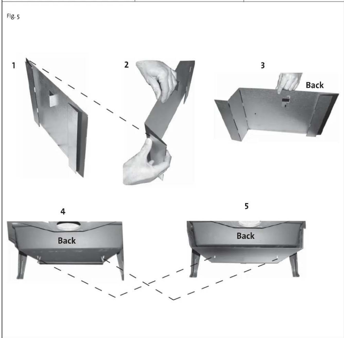
A heat shield for the floor shall always be used. A heat shield for the back can be ordered and mounted depending on the position of the fireplace and the desired distance to combustible materials. See fig. 1.
- The oval top plate is fastened with screws during transport. Remove the screws from underneath the top plate and leave it unattached. This makes it easier for the chimney sweep when the product and the flue pipe have to be cleaned.
- Take out the ash lips, which are inside the burn chamber, and install. The one in front is placed loosely on top of the base plate, while the side ash lip is fastened with the screw that is attached to the base plate.
- Fasten the heat shield under the middle using 2 M6 x 12 screws. Follow the fig. 5.
Mounting of flue pipe
The stove is installed with a 150 mm diameter flue pipe. This must be an approved thickness.
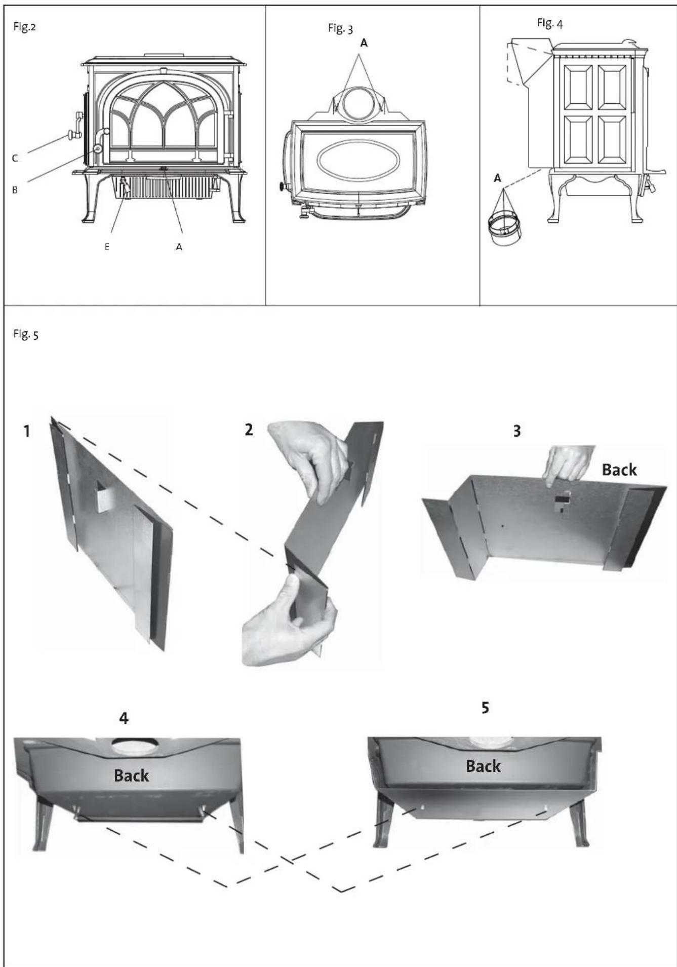
The flue outlet for Jøtul F 500 is inside the burn chamber during transportation. You can choose between a top or rear outlet from the flue pipe. The screws for fastening are in the bag containing screws.
- Flue pipes 150 mm dia. are placed directly onto the product flue outlet. There is a screw on both sides of the product flue outlet (fig. 3A). These are used to fasten the flue pipe.
- Mark where the screws hit the flue pipe when it is at the very bottom of the flue outlet and drill a 5,5 mm hole for the screw in the flue pipe.
- Use gasket and cement to seal between flue pipe and product flue outlet. Place the gasket around the lower part of the flue pipe and fill up the space with cement.
- Fasten the flue pipe with screws.
Note! It is important that the joints are completely sealed. Air leakage etc. may lead to malfunction.
3.6 Control of functions (fig. 2)
When the product is set up, always check the control functions.
These shall move easily and function satisfactorily.
Draught vent (A)
Left position = closed
Right position = fully open
Doorhandle (B)
Towards the left = open
Towards the right = closed
Doorhandle (C)
Towards the right = open
Towards the left = closed
Ash door (E)
Open the door by turning the knob counter-clockwise one half rotation.
3.7 Ash removal
Jøtul F 500 has an ash pan which makes it easy to remove the ash.
-
Scrape the ash through the grate in the base plate and into the ash pan. Use something like a glove to grab the handle on the ash pan.
-
Make sure that the ash pan doesn't fill up so high that it keeps ash from coming through the grate into the pan.
-
Make sure the door to the ash pan is securely shut when the stove is in use.
For the rest, see description of how to handle ash in the Manual on general use and maintenance in Point «6.1 Fire preventive measures».
4.0 Service
Warning! Any unauthorised change to the product is illegal. Only use original spare parts.
4.1 Changing the baffle plate
- The baffle plate consists of a vermeculite plate, and rests on top of the pipes that supply secondary air.
- To remove, just lift it off and out
- To install, follow the same procedure in opposite sequence. Make sure the vermeculite plate is fitted closely against the back wall. Be aware that the vermeculite plate may be damaged by rough handling.
- Then place the insulating blanket on top of the baffle plate.
4.2 Changing the burn plates
- The stove has burn plates that are mounted to the sides and fire bricks in the back.
- Unfasten the screws and remove the burn plates. To reinstall, make sure the insulation is properly fastened to back of the burn plates.
- The bricks at the back are easy to change. Simply lift up a little and pull out.
5.0 Optional equipment
5.2 Connecting pipe for outdoor ventilation - Cat. No. 221031
With the aid of a connecting pipe for outdoor ventilation and a flexible tube, combustion air can be connected to the product directly from the outside. In this manner, the fireplace will always be supplied with the air needed to achieve proper combustion.
Fresh air supply direct from the exterior or from the chimney with air vents
- Insert the connecting pipe into the air inlet under the product.
- Unfold the pipe"s 3 flaps (fig. 5A) inside the air inlet.
- Attach a flexible tube ( 80 mm) directly to the fireplace's connecting pipe by using a hose clamp and attach it to the wall outlet/chimney.
5.2 Rear heat shield- Cat.No. 350956
Assembly instruction follows the product.
ESPAÑOL
text_image
Testum Jolal Team heater finality available tool Standard: Children in diameter to adjacent commercial units tall. Senior and/or other units to adjacent commercial units tall. Trade in diameter to adjacent commercial units tall. Trade in diameter to adjacent commercial units tall. Trade in diameter to adjacent commercial units tall. Trade in diameter to adjacent commercial units tall. Trade in diameter to adjacent commercial units tall. Trade in diameter to adjacent commercial units tall. Trade in diameter to adjacent commercial units tall. Trade in diameter to adjacent commercial units tall. Trade in diameter to adjacent commercial units tall. Trade in diameter to adjacent commercial units tall. Trade in diameter to adjacent commercial units tall. Trade in diameter: 100% Trade in diameter: 100% Trade in diameter: 100% Trade in diameter: 100% Trade in diameter: 100% Trade in diameter: 100% Trade in diameter: 100% Trade in diameter: 100% Trade in diameter: 100% Trade in diameter: 100% Trade in diameter: 100% Trade in diameter: 100% Trade in diameter: 100% Trade in diameter: 100% Trade in diameter: 100% Trade in diameter: 100% Trade in diameter: 100% Trade in diameter: 100% Trade in diameter: 100% Trade in diameter: 100% Trade in diameter: 100% Trade in diameter: 100% Trade in diameter: 100% Trade is not a single, then the only non-mermaidual funds. Mentage and Bedienungsanleitung beachten. Verwerten Sie nur emprechteen Brandstoffe. Beckreden des sonstigen derivatoren. Utilize unmittelment in communisierungen im mermaidus. Fertile no. No. four years, Team plan. Manufacturier: Jipal A5 TOB 2442 No.36-32 Predifikation Narway| Formul Jolal Team heater healthy/healthy food | |||
| Standard Children in the country to be present commercials made in Citation and distribution of the company's market in the local Area of the city, which is expected by the growing population Careholder's daily Affinity Opposition range All type Group of type The group was estimated as a measure for | |||
| Country | Classification | Co-finger standard | Approved by |
| Norway | Kissier-1 | ||
| South | UK | GP | Dr. Montes' Farming-of- Cereansparks total GP |
| a. North | Nordland | PK | Dr. Montes' National Farming and Research institute |
| Follow-up's initiative, are: Our only economical foods Wardings and Bodenungsstratung bruchters. We'vedled 'Se our emittenden Bredicofactors. Described less consignet distribution. Utilise unconsignment and Commissions in remanisms. | |||
| Serifinal Y. yxxx, Year 2006 | |||
| Manufacturant: Jolal AS POB 1441 No-2632 Predilikstad Hormley | 222,745 | ||
Durchmesser: 2 - 5 cm
Brennholz (Scheite):
Durchmesser: ca. 8 - 13 cm
Product: Jøtul F 500
text_image
Y X 700 61Min. mål gulvplate / measure floorplate X/Y = Acc. to national standards and regulations
text_image
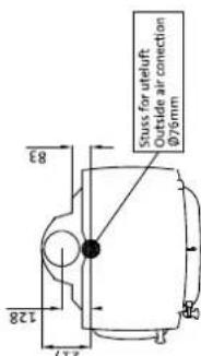
128 217 83 Stuss for uteluft Outside air convection Ø76mm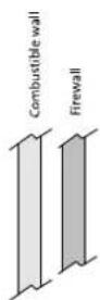
Målene gjelder ubehandlede produkter. Etter lakkering eller emaljering kan målene variere noe. Dimensions refer to untreated products. After painting or enamelling dimensions may have small divergences.
Quality control of stoves and fireplaces
Checked