FS 92 - Fireplace Jøtul - Free user manual and instructions
Find the device manual for free FS 92 Jøtul in PDF.
| Product type | Freestanding fireplace with surround (insert) |
| Brand | Jøtul |
| Model | FS 92 |
| Combustion chamber material | Painted cast iron |
| Surround material | Concrete |
| Dimensions (H x W x D) | 1570 x 525 x 480 mm |
| Total weight (chamber + surround) | Approximately 281 kg (117 + 164 kg) |
| Nominal power output | 6.0 kW |
| Energy efficiency | 79% |
| Recommended fuel | Wood logs (max length 30 cm) |
| Flue connection | Diameter 150 mm, top or rear outlet |
| External air intake (optional) | Diameter 100 mm, aluminium flexible |
| Recommended chimney draft | 12 Pa |
| Average flue gas temperature | 360 °C |
| CO emissions (at 13% O₂) | 0.08% (967 mg/m³) |
| Operating mode | Intermittent (adding wood on embers) |
| Minimum safety distances (flammable walls) | See figure 1 of the manual (e.g., 344 mm lateral, 100 mm rear) |
| Minimum distance to flammable ceiling | 500 mm |
| Certification standard | EN 13240 |
| Warranty (external cast iron parts) | Material and manufacturing defects |
| Available options | Glass floor plate, external air connection |
| Routine maintenance | Remove cold ashes, regular chimney sweeping, do not obstruct air inlets |
| Important safety instructions | Do not use liquid fuel, keep flammable materials away, in case of chimney fire close all air inlets and call the fire department |
Frequently Asked Questions - FS 92 Jøtul
User questions about FS 92 Jøtul
0 question about this device. Answer the ones you know or ask your own.
Ask a new question about this device
Download the instructions for your Fireplace in PDF format for free! Find your manual FS 92 - Jøtul and take your electronic device back in hand. On this page are published all the documents necessary for the use of your device. FS 92 by Jøtul.
USER MANUAL FS 92 Jøtul
GB - Installation and Operating Instructions 41
natural_image
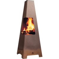
White cylindrical industrial stove burner with black glass panel showing visible flames (no text or symbols)text_image
Product Actual Items not labeled by product Order list This is also labeled for the product and its parts. This is deferred to discontinue but the materials. This is also labeled for the product. Order list Order type Order name Order description Original Cut off this part and replace the label already attached to the product with this one.| Country | Gross Country | Gross Domestic insured | Approved by |
| Germany | Korea | ||
| Sweden | UK | sp | 25 Suisse from Sweden Nordmarkfurt AS |
| Switzerland | Poland | sp | 25 Suisse of Sweden Nordmarkfurt AS |
Nominell varmeavgivelse: 6,0 kW
Røykgass massestrøm: 6,0 g/s
natural_image
Technical line drawing of a mechanical or architectural component with no visible text or symbolsNORSK
text_image
Technical diagram showing cross-sectional views of a structural component with labeled dimensions and annotationsnatural_image
Architectural cross-section diagram showing room layouts and structural elements (no text or labels)natural_image
Architectural cross-section diagram showing structural layers and doorways (no text or labels)3.7 Stålskorstein
text_image
Technical diagram of a mechanical device with labeled components A, B, and C, showing cross-sectional views and assembly lines.natural_image
Technical line drawing of a mechanical assembly with no visible text or symbolsnatural_image
Technical line drawing of a mechanical assembly with no visible text or symbolsnatural_image
Technical line drawing of a mechanical component with a central bracket and mounting holes (no text or symbols)natural_image
Technical line drawing of a mechanical assembly with cross-sectional view (no text or symbols)text_image
Technical diagram of a mechanical device with labeled components A and B, showing internal structure and mounting points.natural_image
Technical line drawing of a mechanical component with internal structure and mounting holes (no text or symbols)- Monter bakstykket. Pass på at det er kant i kant med sokkelen. Bakstykket limes med medfølgende akryllim.
Fig. 13
natural_image
Technical line drawing of a mechanical component with mounting holes and internal features (no text or symbols)natural_image
Technical diagram of a mechanical assembly with cross-sectional views and labeled component A (no text or symbols present)natural_image
Technical diagram of a mechanical device with labeled component A and directional arrows indicating motion (no text or symbols beyond labels)natural_image
Technical line drawing of a mechanical component with internal flow arrows (no text or symbols)5.0 Ferdig montert
text_image
Product Detail Items not linked by product Ordered When a label is required for reference to the materials. Where are due to the material used in the materials. From 120% of the material used in the material. Ordering Ordering Ordering Ordering Ordering Ordering Ordering Ordering Ordering Ordering Ordering Ordering Ordering Ordering Ordering Ordering Ordering Ordering Ordering Ordering Ordering Ordering Ordering Ordering Ordering Ordering Ordering Ordering Ordering Ordering Ordering Ordering Ordering Ordering Outer Outer Outer Outer Outer Outer Outer Outer Outer Outer Outer Outer Outer Outer Outer Outer Outer Outer Outer Outer Outer Outer Outer Outer Outer Outer Outer Outer Outer Outer Outer Outer Outer Outer Outer Outer Outer Outer Outer Outer Outer Outer Outer Outer Outer Outer Outer Outer Outer Outer Inner: Outer labels are shown in the original form. Inner labels are shown in the original form. Inner labels are shown in the original form. Inner labels are shown in the original form. Inner labels are shown in the original form. Inner labels are shown in the original form. Inner labels are shown in the original form. Inner labels are shown in the original form. Inner labels are shown in the original form. Inner labels are shown in the original form. Inner labels are shown in the original form. Inner labels are shown in the original form. Inner label is also shown in the original form. Inner label is also shown in the original form. Inner label is also shown in the original form. Inner label is also shown in the original form. Inner label is also shown in the original form. Inner label is also shown in the original form. Inner label is also shown in the original form. Inner label is also shown in the original form. Inner label is also shown in the original form. Inner label is also shown in the original form. Inner label is again shown in the original form. Inner label is again shown in the original form. Inner label is again shown in the original form. Inner label is again shown in the original form. Inner label is again shown in the original form. Inner label is again shown in the original form. Inner label is again shown in the original form. Inner label is again shown in the original form. Inner label is again shown in the original form. Inner label is again shown in the original form. Inner label is also shown in the original form. Inner label is also shown in the original form. Inner label is also shown in the original form. Inner label is also shown in the original form. Inner label is also shown in the original form. Inner label is also shown in the original form. Inner label is also shown in the original form. Inner label is also shown in the original form. Inner label is also shown in the original form. Inner label is both 'and' and 'out' and 'out' and 'out' and 'out' and 'out' and 'out' and 'out' and 'out' and 'out' and 'out' and 'out' and 'out' and 'out' and 'out' and 'out' and 'out' and 'out' and 'out' and 'out' and 'out' and 'out' and 'out' and 'out' and 'out' and 'out' and 'out' end| Country | Graduation | Estimated Student | Approved |
| Germany | Klaus | ||
| Sweden | US | pg | 25 Stentes froming an satzungsstrategisch AS |
| Switzerland | Austria | pg | 25 Stentes froming an satzungsstrategisch AS |
Nominel varmeafgivelse: 6,0 kW
Røggas massestrøm: 6,0 g/s
CO-emission (13% O _2 ): 967 mg/m ^3
Støv: < 20 mg/m³n @ 13 % O₂
Røggastemperatur: 305°C
Driftsform: Intermitterende
natural_image
Architectural cross-section diagram showing room layouts and structural elements (no text or labels)text_image
Technical diagram showing cross-sectional views of a structural component with labeled dimensions A and D.natural_image
Architectural cross-section diagram showing room layouts and structural elements (no text or labels)natural_image
Architectural line drawing of a building facade with vertical columns and horizontal beams (no text or symbols)3.7 Stålskorsten
text_image
Technical diagram of a mechanical device with labeled components A, B, and Cnatural_image
Technical line drawing of a mechanical assembly with no visible text or symbolsnatural_image
Technical line drawing of a mechanical assembly with no visible text or symbolstext_image
Technical diagram of a mechanical component with labeled parts marked 'A', including a logo and emblem.natural_image
Technical line drawing of a mechanical component with a central lever and flange (no text or symbols)natural_image
Technical diagram of a mechanical assembly with cross-sectional and top views (no text or symbols)text_image
Technical diagram of a mechanical device with labeled parts A and B, showing internal components and structural details.natural_image
Technical line drawing of a mechanical component with no visible text or symbols- Monter bagstykket. Pas på at det er kant i kant med sokkelen. Bagstykket limes med medfølgende akryllim.
Fig. 13
natural_image
Technical line drawing of a mechanical component with mounting holes and fasteners (no text or symbols)natural_image
Technical diagram of a mechanical assembly with cross-sectional views and labeled component A (no text or symbols present)natural_image
Technical diagram of a mechanical device with labeled component A, showing internal components and directional arrows (no text or symbols beyond labels)natural_image
Technical line drawing of a mechanical component with internal flow arrows (no text or symbols)5.0 Ferdig montert
text_image
Product Detail Items not linked by label or Order list Where is a label that is recommended for materials. Where is a label to be designated but the materials. Where is a label to be approved. Order list Order type Order name: 100000000000000000000000000000000000000000000000000000000000000000000000000000000000000000000000000 Order list Order type Order name: 100000000000000000000 Order list Order type Order name: 12567888888888888888888888888888888888888888888888888888888888888888888888888888888888888888888 Original Order list Order type Order name: 125678888888888888888888888888888888888888888888888888888| Feature Jedal Room layout final boundary hall | |||
| Standard Class: 100% of classes in commercial areas. Type: 100% of classes in commercial areas In use of class 100% of classes in commercial areas. The general procedure: Standard: 100% Subtitle Specification range: Total size Special size The general procedure is written by: Country Classification Ice-Factor Management Keywords by: Warranty Event-1 Balance Risk Not applicable Risk P. Konsages from sign-off and Copyrights for the last 40 Not applicable Risk Not applicable Risk Not applicable Risk Not applicable Risk Not applicable Risk Not applicable Risk Not applicable Risk Not applicable Risk Not applicable Risk Not applicable Risk Not applicable Risk Not applicable Risk Not applicable Risk Not applicable Risk Not applicable Risk Not applicable Risk Not applicable Risk Not applicable Risk Not applicable Risk Not applicable Risk Not applicable Risks Not applicable Risk Not applicable Risk Not applicable Risk Not applicable Risk Not applicable Risk Not applicable Risk Not applicable Risk Not applicable Risk Not applicable Risk Not applicable Risk Not applicable Risk Not applicable Risk Not applicable Risk Not applicable Risk Not applicable Risk Not applicable Risk Not applicable Risk Not applicable Risk Not applicable Risk Not applicable Risk Not applicable Risk Not applicable Risk Not applicable Risk Not applicable Risk Not applicable Risk Not applicable Risk Not applicable Risk Not applicable Risk Not applicable Risk Not applicable Risk Not applicable Risk Not applicable Risk Not applicable Risk Not applicable Risk Not applicable Risk Not applicable Risk Not applicable Risk Not applicable Risk Not applicable Risk Not applicable isk Not applicable Risk Not applicable Risk Not applicable Risk Not applicable Risk Not applicable Risk Not applicable Risk Not applicable Risk Not applicable Risk Not applicable Risk Not applicable Risk Not applicable Risk Not applicable Risk Not applicable Risk Not applicable Risk Not applicable Risk Not applicable Risk Not applicable Risk Not applicable Risk Not applicable Risk Not applicable risk Not applicable Risk Not applicable Risk Not applicable Risk Not applicable Risk Not applicable Risk Not applicable Risk Not applicable Risk Not applicable Risk Not applicable Risk Not applicable Risk Not applicable Risk Not applicable Risk Not applicable Risk Not applicable Risk Not applicable Risk Not applicable Risk Not applicable Risk Not applicable Risk Not applicable Risk Not applicable 风险 Not applicable Risk Not applicable Risk Not applicable Risk Not applicable Risk Not applicable Risk Not applicable Risk Not applicable Risk Not applicable Risk Not applicable Risk Not applicable Risk Not applicable Risk Not applicable Risk Not applicable Risk Not applicable Risk Not applicable Risk Not applicable Risk Not applicable Risk Not applicable Risk Not applicable Risk Not applicable risk Not applicable Risk Not applicable Risk Not applicable Risk Not applicable Risk Not applicable Risk Not applicable Risk Not applicable Risk Not applicable Risk Not applicable Risk Not applicable Risk Not applicable Risk Not applicable Risk Not applicable Risk Not applicable Risk Not applicable Risk Not applicable Risk Not applicable Risk Not applicable Risk Not applicable Risk Not applicable Konsages Not applicable Mortgage and Bedden organization business. Vermilion, Special enrollment, non-allocation. Described (excl. management or distribution) Institute compensation to commercialities in commercialities. Seal Mio No. Yovice, Year 2026. Manufactur... Jouai A5 POB 1444 No.1602 Indirectated Norway 2026 | |||
CO-emission (13% O _2 ): 967 mg/m ^3
natural_image
Architectural cross-section diagram showing room layouts and structural elements (no text or labels)text_image
Technical diagram showing a cross-sectional view of a building or structure with labeled components and directional arrows.natural_image
Technical line drawing of a mechanical or architectural component with layered structure and no visible text or symbolsnatural_image
Architectural line drawing of a building facade with vertical columns and horizontal beams (no text or symbols)3.7 Stålskorsten
natural_image
Technical line drawing of a mechanical assembly with no visible text or symbolsnatural_image
Technical line drawing of a mechanical assembly with no visible text or symbolstext_image
Technical diagram of a mechanical component with labeled parts A and a logo, likely for assembly or manufacturing documentation.natural_image
Technical line drawing of a mechanical component with a central bracket and mounting holes (no text or symbols)natural_image
Technical diagram of a mechanical assembly showing top and side views of a device component (no text or symbols)text_image
Technical diagram of a mechanical device with labeled parts A and B, showing internal components and structural details.natural_image
Technical line drawing of a mechanical component with no visible text or symbolsnatural_image
Technical line drawing of a mechanical component with mounting holes and internal features (no text or symbols)natural_image
Technical diagram of a mechanical assembly with cross-sectional views and labeled component A (no text or symbols present)natural_image
Technical line drawing of a mechanical component with internal components and directional arrows (no text or symbols)5.0 After montering
text_image
Product Label From not to be tested by product Label The product value for the product is not available. The product value is displayed but the material is and the product is written out of the material. Product name: Product type: Name: Description: Product name: Product type: Name: Description: Description: Description: Description: Description: Description: Description: Description: Description: Description: Description: Description: Description: Description: Description: Description: Description: Description: Description: Description: Description: Description: Description: Description: Description: Description: Description: Description: Description: Description: Description: Description: Description: Description: Cut off this part and replace the label already attached to the product with this one. Original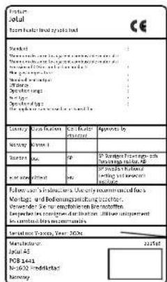
natural_image
Architectural cross-section diagram showing room layouts and staircases (no text or labels)natural_image
Architectural cross-section diagram showing structural layers and staircases (no text or labels)natural_image
Architectural cross-section diagram of a building facade with pipes and structural elements (no text or labels)natural_image
Architectural cross-section diagram showing structural layers and supports (no text or labels)3.7 Terässavupiippu
text_image
Technical diagram of a mechanical device with labeled components A, B, and Cnatural_image
Technical line drawing of a mechanical assembly with no visible text or symbolsnatural_image
Technical line drawing of a mechanical assembly with no visible text or symbolstext_image
J0010 A A A Anatural_image
Technical line drawing of a mechanical component with a central lever and flange (no text or symbols)natural_image
Technical diagram of a mechanical assembly with cross-sectional view and top view (no text or symbols)text_image
Technical diagram of a mechanical device with labeled parts A and B, showing internal components and structural details.natural_image
Technical line drawing of a mechanical component with internal cavity and mounting holes (no text or symbols)natural_image
Technical line drawing of a mechanical assembly with mounting holes and internal components (no text or symbols)natural_image
Technical diagram of a mechanical assembly with cross-sectional views and labeled component A (no text or symbols present)natural_image
Technical line drawing of a mechanical device with labeled component A and directional arrows (no text or symbols beyond labels)natural_image
Technical line drawing of a mechanical component with internal flow arrows (no text or symbols)1.0 Relationship to the authorities......41
2.0 Technical data 41
3.0 Safety....43
4.0 Installation....44
5.0 Installation completed ....48
6.0 Optional Extras 48
7.0 Recycling 49
8.o Warranty 49
text_image
Product Detail Items not linked to a label Order list When a label is required for reference to the material. When a label is deleted to the material but the materials. When a label is not allowed to replace it. Order list Order type Order name or number of items Order name Order type Order name Order type Order name Order type Order name Order type Order name Order type Order name Order type Order name Order type Order name Order type Order name Order type Order name Order type Order name Order type Order name Order type Order name Order type Order name Order type Order name Order type Order name Order type Order name Order type Order name, Order type, Order name, Order type, Order name, Order type, Order name, Order type, Order name, Order type, Order name, Order type, Order name, Order type, Order name, Order type, Order name, Order type, Order name, Order type, Order name, Order type, Order name, Order type, Order name, Order type, Order name, Order type, Order name, Order type, Order name, Order type, Order name, Order type, Order name, Order name, Order type, Order name, Order name, Order type, Order name, Order name, Order type, Order name, Order name, Order type, Order name, Order name, Order type, Order name, Order name, Order type, Order name, Order name, Order type, Order name, Order name, Order type, Order name, Order name, Order type, Order name, Order name, Order type, Order name, Order name, Order type, Order name, Order list Order type Order name Order name Order type Order name Order name Order type Order name Order name Order type Order name Order name Order type Order name Order name Order type Order name Order name Order type Order name Order name Order type Order name Order name Order type Order name Order name Order type Order name Order name Order type Order name Order name Order type Order name Order name: Order label: 100% Order label: 100% Order label: 100% Order label: 100% Order label: 100% Order label: 100% Order label: 100% Order label: 100% Order label: 100% Order label: 100% Order label: 100% Order label: 100% Order label: 100% Order label: Not specified (the label is already attached to the product with this one) Cut off this part and replace the label already attached to the product with this one.On all our products there is a label indicating the serial number and year. Write this number in the place indicated in the installation instructions.
Always quote this serial number when contacting your retailer or Jøtul.
Serial no.
1.0 Relationship to the authorities
Jøtul FS 91 /FS 92 is a freestanding product using the Jøtul F 480 as the burn chamber, which can be positioned against inflammable walls at the distances described in fig. 1.
The installation of a fireplace must be carried out in compliance with national laws and regulations. All local ordinances must also be complied with when products are installed.
Installation instructions for the stove accompany the surround. Installation and operating instructions for the fireplace insert accompany the insert. For day-to-day use, maintenance, service work, etc. see the General user and maintenance manual.
Contact your local building authorities regarding restrictions and installation requirements.
The product may not be used until it has been inspected and approved by qualified personnel.
The product has been tested and documented as a freestanding stove in accordance with EN 13240.
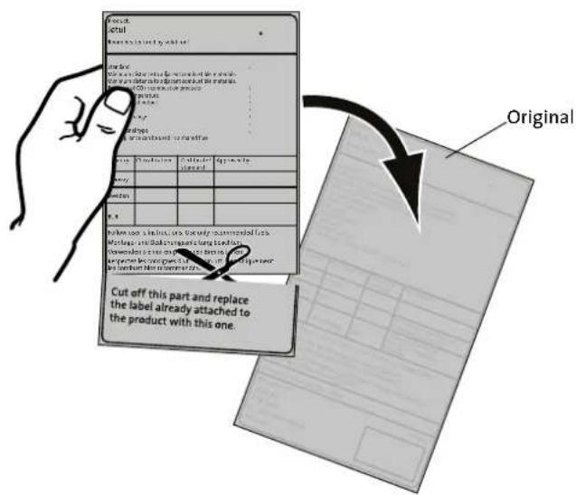
The approval label for the freestanding product comes with the installation instructions for the surround, and must be cut and placed on top of the plate attached to the burn chamber.
2.0 Technical data
Material: Cast iron/concrete
Finish, burn chamber: Paint
Type of fuel: Wood
Max. log length: 30 cm
Smoke outlet: Top, rear
Flue pipe dimension: ∅ 150 mm
Outside air connection: Alu. flex - ∅ 100 mm
Weight, burn chamber, approx.: 117 kg
Weight, surround, approx.: 164 kg
Height: 1570 mm
Width: 525 mm
Depth: 480 mm
Minimum distance to ceiling: 500 mm
Product dimensions, distances: See fig. 1
Technical data in acc. with EN 13240
| Nominal heat output: | 6,0 kW |
| Flue gas mass flow: | 6,0 g/s |
| Recommended chimney draught: | 12 Pa |
| Efficiency: | 79%@6 kW |
| CO emissions (13% O_2 ): | 0,08% |
| CO emissions (13% O_2 ): | 967 mg/ m^3 |
| Dust: | < 20 mg/ m^3 n @ 13 % O_2 |
| Flue gas temperature: | 305°C |
| Operational type: | Intermittent |
Intermittent combustion here means normal use of a fireplace, i.e. add more fuel as soon as the fire has burned down to embers.
Jøtul FS 91 / FS 92
Fig. 1
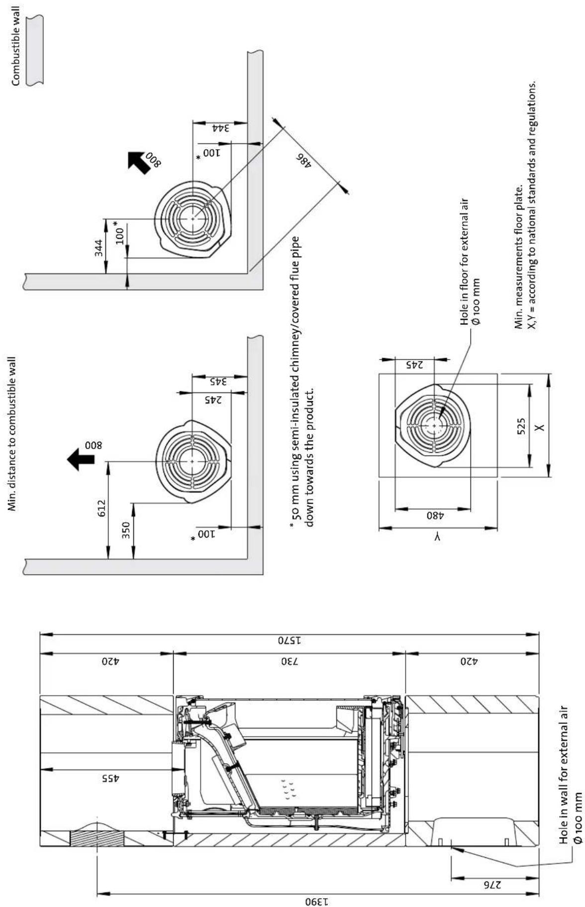
* 50 mm using semi-insulated chimney/covered flue pipe
down towards the product.
Min. measurements floor plate.
X,Y = according to national standards and regulations.
900134-P01
3.0 Safety
NB! To guarantee optimal performance and safety, Jøtul recommends that its stoves are fitted by a qualified installer (see www.jotul.com for a complete list of dealers).
Any modifications to the product by the distributor, installer or consumer may result in the product and safety features not functioning as intended. The same applies to the installation of accessories or optional extras not supplied by Jøtul. This may also be the case if parts that are essential to the functioning and safety of the fireplace have been disassembled or removed.
In all these cases, the manufacturer is not responsible or liable for the product and the right to make a complaint becomes null and void.
3.1 Fire Prevention Measures
There is a certain element of danger every time you use your fireplace. The following instructions must therefore be followed:
- The minimum safety distances when installing and using the fireplace are given in fig. 1.
- Ensure that furniture and other flammable materials are not too close to the fireplace. Flammable materials should not be placed within 1 metre of the fireplace.
- Allow the fire to burn out. Never extinguish the flames with water.
- The fireplace becomes hot when lit and may cause burns if touched.
- Only remove ash when the fireplace is cold. Ash can contain hot embers and should therefore be placed in a non-flammable container.
- Ash should be placed outdoors or be emptied in a place where it will not present a potential fire hazard.
In case of chimney fire:
- Close all hatches and vents.
- Keep the firebox door closed.
- Check the loft and cellar for smoke.
- Call the fire service.
- Before use after a fire an expert must check the fireplace and the chimney in order to ensure that it is fully functional.
3.2 Floor
Foundation
You need to make sure the foundation is suitable for a fireplace. See «2.0 Technical Data» for specified weight.
We recommend the removal of any flooring that is not attached to the foundation («floating floors») beneath the installation.
Requirements for protection of wooden flooring beneath the fireplace
The product has integrated floor protection and may therefore be placed directly on a wooden floor.
Any inflammable floor coverings, such as linoleum, carpets, etc. must be removed from under the product.
Requirements for protection of inflammable floors in front of the fireplace
The front plate must comply with national laws and regulations. Contact your local building authorities regarding restrictions and installation requirements.
3.3 Walls
Distance to walls made of combustible material - see fig. 1.
The fireplace may be used with an uninsulated flue pipe provided the distances between the fireplace and walls made of combustible materials are as shown in fig. 1.
Ensure that furniture and other flammable materials are not too close to the fireplace. Flammable materials should not be placed within 800 mm of the fireplace.
3.4 Ceiling
If the ceiling above the fireplace is made of a combustible material, the minimum distance between the fireplace and ceiling must be 500 mm.
3.5 Air supply
There must be a flow of air between the burn chamber and the surround. This is to ensure that any build-up of heat inside the surround is not too great. NB: It is extremely important not to cover air openings. See fig. 1 for distances.
ENGLISH
3.6 External air
The amount of combustion air for Jøtul's products is approximately 25-40 m ^3 /h.
A flexible supply hose allowing external air to be fed directly into the product can be installed as follows:
- Through a hole cut where marked in the bottom plate.
• Through the hole at the back of the surround.
Suggested installation of the flexible hose for combustion air:
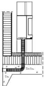
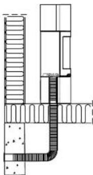
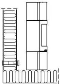
Fig. 2a, through an outside wall
natural_image
Architectural cross-section diagram showing room layouts and structural elements (no text or labels)Fig. 2b, through the floor and ground plate
text_image
Technical diagram of a mechanical or hydraulic system with labeled components and cross-sectional viewsFig. 2c, through the floor and basement
natural_image
Architectural cross-section diagram showing room layouts and structural elements (no text or labels)Fig. 2d, indirectly through an outside wall
natural_image
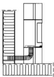
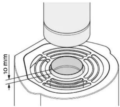
Architectural cross-section diagram showing structural layers and doorways (no text or labels)3.7 Steel chimney
If a top-mounted steel chimney is used, an uninsulated pipe must run from the insert to approximately 10 mm over the top grate.
Fig. 3
text_image
10 mmThen fit the steel chimney in accordance with the operating instructions.
4.0 Installation
NB: Check that the fireplace is undamaged before installation begins.
NB: The product is heavy! Ensure you have help when positioning and installing it. Make sure the product does not topple over.
NB: Read the Installation and Operating instructions carefully before installing the fireplace!
It is recommended that you test-mount the surround to adjust the insert and flue pipe connection.
Use the acrylic sealant provided for all joints.
4.1 Prior to installation
The basic product comes in two packages:
-
Burn chamber.
-
Concrete units with mounting sections.
NB: Check that there is no visible damage to the product when you unpack it.
Preparations
Before installation, it is necessary to decide:
• Where the smoke outlet is to be located.
• Possible use and location of external air supply.
Refer to manuals for installation of the parts.
You will need the following tools to install the product: Spirit level, ratchet with 10 mm and 13 mm sockets and hex keys with 5 mm socket.
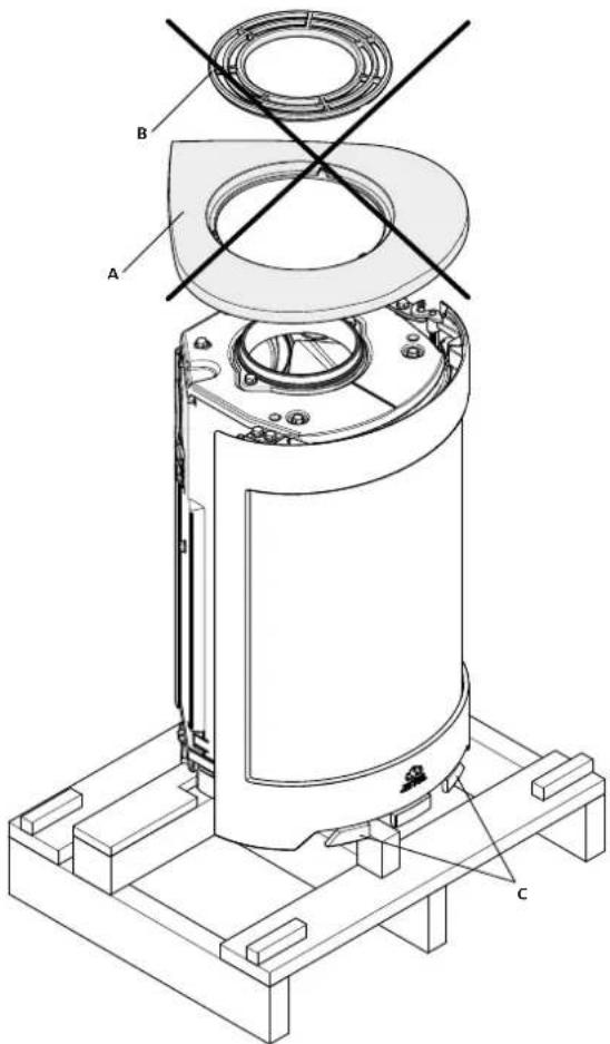
Fig. 4
text_image
A B C- Remove the packaging (cardboard and wooden frame) and spread the cardboard out on the floor behind the fireplace.
- Leave the stove standing on the transport pallet.
- Remove the top plate (Fig. 4 A) with the top grate (Fig. 4 B). These parts are not to be used.
- Remove the gloves and bowl from the ash pan. The bowl will not be used.
- Check that the control handles (Fig. 4 C) move freely.
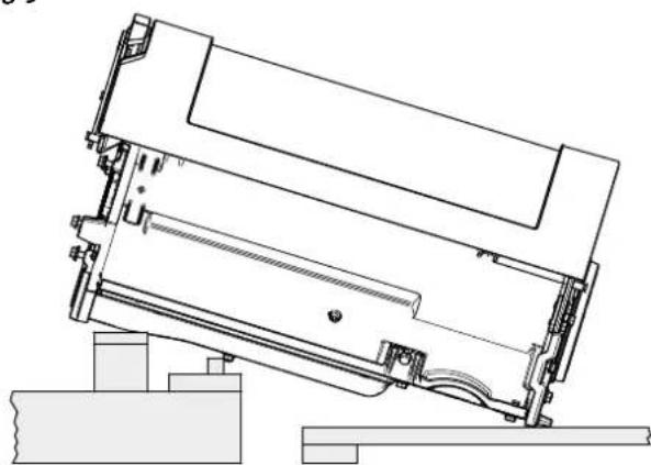
Fig. 5
natural_image
Technical line drawing of a mechanical assembly with no visible text or symbols- Carefully lay the stove down on its back. Rest the stove on a pallet and three packaging frames (see Fig. 5).
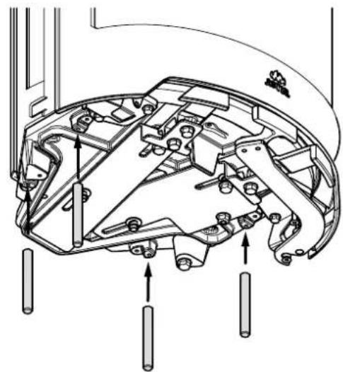
Fig. 6
natural_image
Technical line drawing of a mechanical assembly with no visible text or symbols- Screw in the 4 threaded bars.
Fig. 7
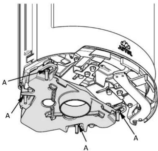
text_image
J019L A A A A- Mount the outside air connection with 4 nuts and washers (Fig. 7 A).
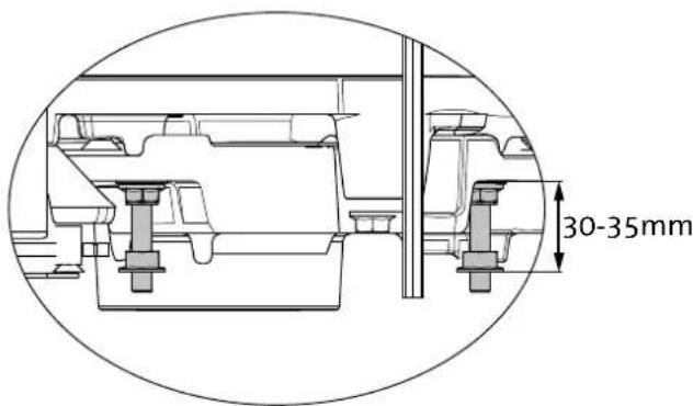
text_image
30-35mm- Mount the adjusting nuts on threaded bars.
ENGLISH
4.2 Chimney and flue pipe
- The fireplace must only be connected to a chimney and flue pipe approved for solid fuel fireplaces with flue gas temperatures as specified in «2.0 Technical Data».
- The cross-section of the chimney must be designed to fit the fireplace. Use «2.0 Technical Data» to calculate the correct chimney cross-section.
- The chimney must be connected in accordance with the installation instructions of the chimney supplier.
- Before a hole is made in the chimney, the product should be test-mounted in order to correctly mark the position of the fireplace and the hole in the chimney. See Fig.1 for minimum dimensions.
• Make sure that the flue pipe rises all the way up to the chimney. - With a rear outlet, use a flue pipe bend with a sweep hatch to allow sweeping.
- Please note that it is extremely important for connections to have a degree of flexibility. This is to prevent any movement in the installation leading to the formation of cracks.
- For recommended chimney draught, see «2.0 Technical Data». For flue pipe dimensions with the relevant cross-section, see «2.0 Technical Data».
NB! The minimum recommended chimney length is 3.5 m from the flue pipe insert. If the draught is too strong, a flue pipe damper can be installed and used to reduce the draught.
4.3 Installation
Fig. 8
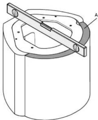
natural_image
Technical drawing of a mechanical component with a central lever and flange (no text or symbols)- The base should be put in place. Check it is level using a spirit level and adjust as necessary using adhesive or mortar.
- Mount the lip (A) with acrylic glue.
Fig. 9
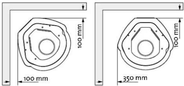
text_image
100 mm 100 mm 350 mm 100 mm- Placement of the fireplace. See Fig 1 for details.
Fig. 10
natural_image
Technical diagram of a mechanical assembly showing top and side views of a device component (no text or symbols)When using the outside air connection (optional extra, cat. no. 51012164), this must be fitted now.
- Position the burn chamber in the four holes in the baseplate.
- Make sure that the flexible hose for combustion air is not trapped. Route the hose out through the hole in the rear of the base.
- The approval label, which is attached by a wire, is fed under the burn chamber and down into the base.
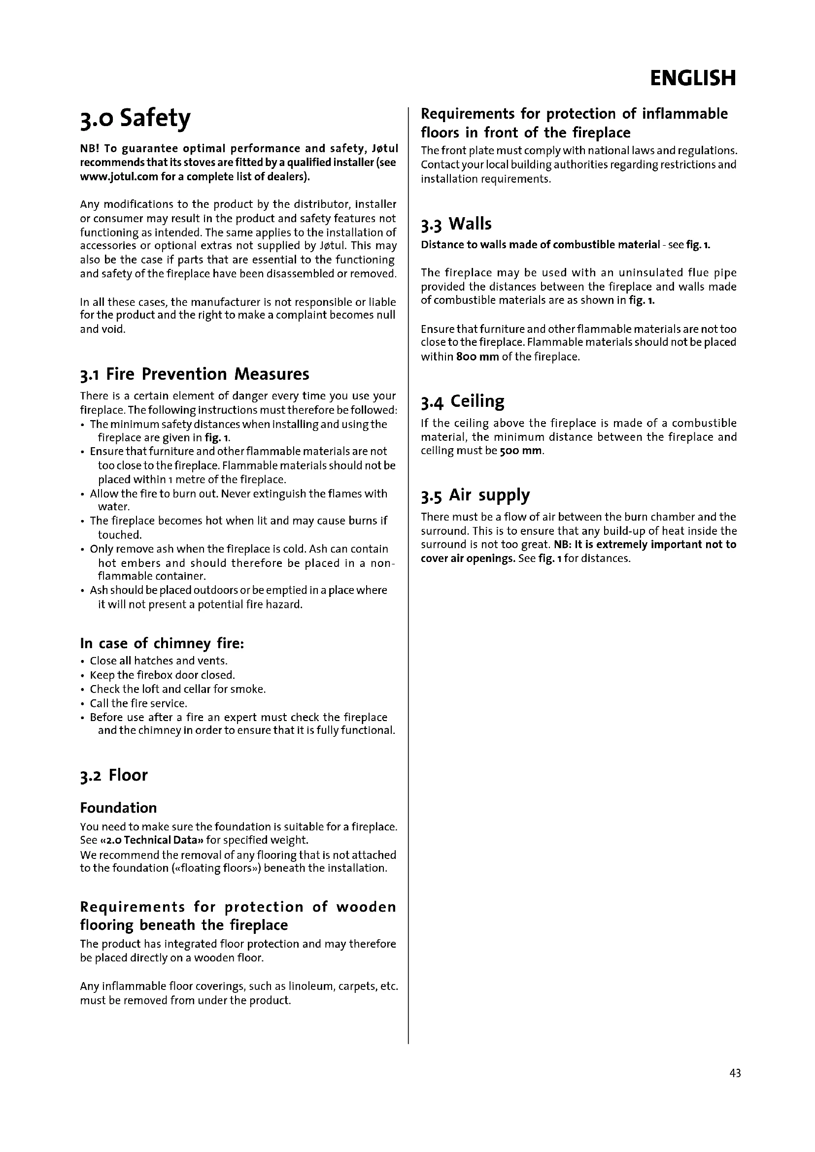
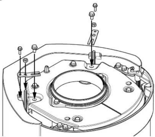
Fig. 11
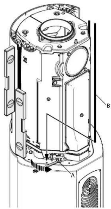
text_image
Technical diagram of a mechanical device with labeled parts A and B, showing internal components and structural details.- Adjust the burn chamber horizontally so that it is flush with the front of the base.
- Level and adjust the burn chamber vertically with the nuts (Fig. 11A). NB: It is extremely important for the burn chamber to be vertically level!
- Mount the 2 long threaded bars (Fig. 11 B).
Fig. 12
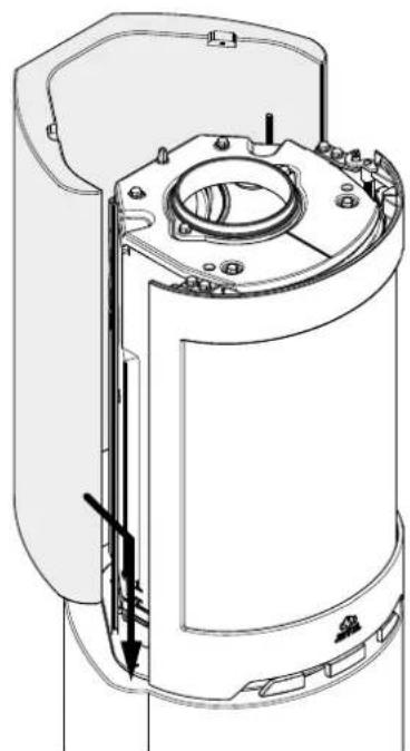
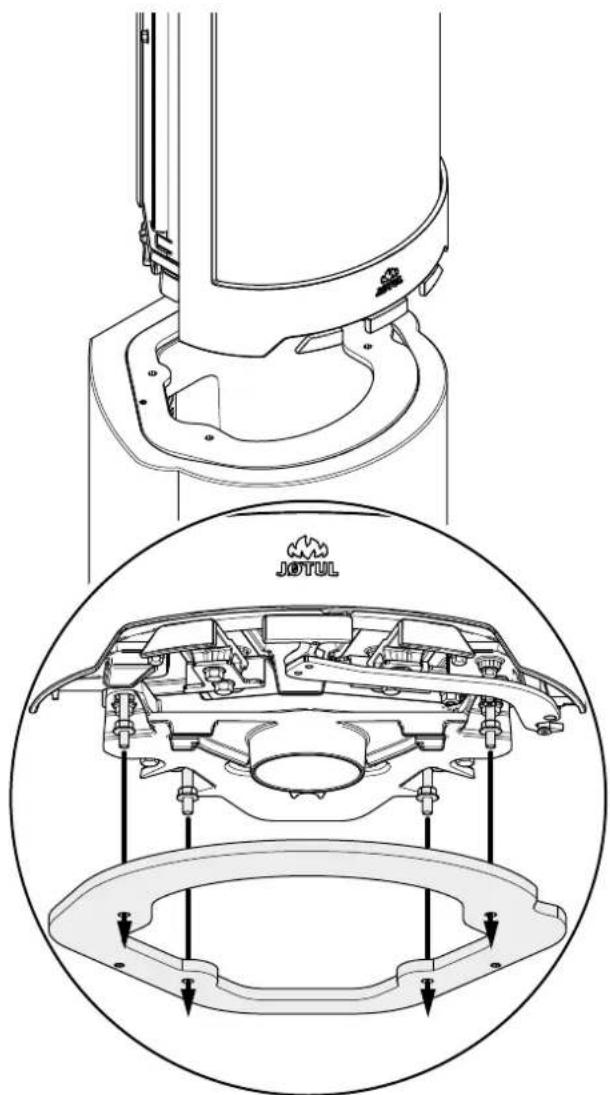
natural_image
Technical line drawing of a mechanical component with internal components and directional arrows (no text or symbols)- Mount the rear part of the surround. Make sure it is aligned with the base. Use the acrylic glue provided for gluing the rear part.
Fig. 13
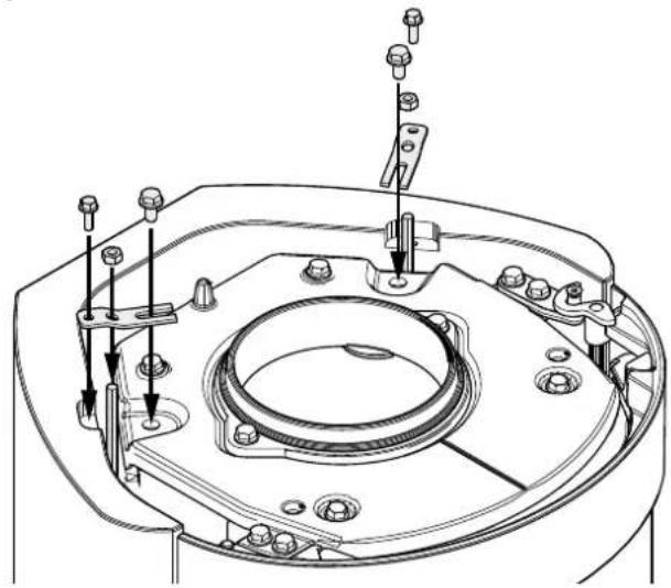
natural_image
Technical line drawing of a mechanical assembly with mounting holes and internal components (no text or symbols)- Mount the brackets on the upper side of the rear part of the surround and the insert. Fasten the long threaded bars with the wing nuts.
Fig. 14
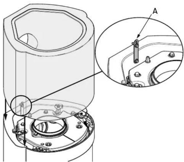
natural_image
Technical diagram of a mechanical assembly with cross-sectional views and labeled component A (no text or symbols present)- Mount the upper part of the surround. Make sure it is aligned with the rear part. Glue the upper part to the rear part with the acrylic glue provided. Mount the bracket (A) to fasten the rear and upper part of the surround together.
ENGLISH
Fig. 15
Installation using a top outlet/steel chimney:
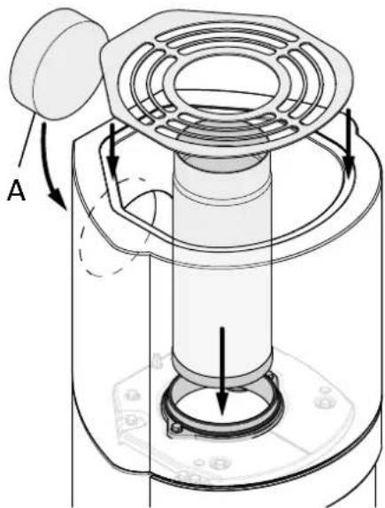
natural_image
Technical diagram of a mechanical device with labeled component A, showing internal components and directional arrows (no text or symbols beyond labels)Use the acrylic glue provided for mounting the cover (A).
Fig. 16
Installation using a rear outlet:
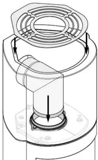
natural_image
Technical line drawing of a mechanical component with internal flow arrows (no text or symbols)5.0 Installation completed
See Installation instructions with technical data for Jøtul F 480 (cat. no. 10047258) for use and maintenance of the product!
5.1 Painting
Painting can take place the day after installation. Use waterbased paint. If you prefer a little surface texture, a little tile cement may be mixed into the paint.
5.2 Minor damage
Once the insert has been installed you should fill in any nicks or irregularities in the concrete. You can use the accompanying cement filler.
- In order to achieve the best result the surround should be rubbed down with fine sandpaper, smoothing any unevenness or sharp edges prior to painting.
- Then apply one coat.
- Mix the powder (cement filler) with water to form a smooth paste (like toothpaste).
- Smooth away any unevenness, allow to dry and rub down with fine sandpaper.
- If the hole is deep, we recommend that the filler be applied in two stages to prevent it sinking.
- Apply a second coat of the desired colour.
5.3 Cracks
In some instances, small cracks may appear at the joints after a few months' use due to settling of the building. These cracks can be easily repaired:
- Open up the crack with a tool, e.g. a screwdriver, to create more room for the grouting cement.
- First remove any dust using a vacuum cleaner. Then inject some acrylic grout, and smooth it off using a wet, soapy fingertip.
• After a couple of days the joint can be repainted.
6.0 Optional extras
Floor plate in front of the product, glas
Cat. no. 50044652
External air connection
Cat. no. 51012164
7.0 Recycling
7.1 Recycling packaging
Your fireplace is delivered with the following packaging:
- A wooden pallet that can be cut up and burned in the fireplace.
- Cardboard packaging that should be taken to a local recycling facility.
- Plastic bags that should be taken to a local recycling facility.
7.2 Recycling the fireplace
The fireplace is made of:
• Metal that should be taken to a local recycling facility.
- Glass that should be disposed of as hazardous waste. The glass in the fireplace must not be placed in a regular source segregation container.
- Vermiculite burn plates that can be disposed of in regular waste containers.
8.o Warranty
Jøtul AS provides its customers with a ten-year warranty with the right to return external cast-iron items if they show defects as a result of faulty materials and/or manufacturing after the initial purchase/installation of the fireplace. The buyer is entitled to return the goods provided that the fireplace has been installed in compliance with current laws and regulations and in compliance with Jøtul's installation and operating instructions.
The warranty does not cover:
The installation of optional extras, for example, to rectify local draught conditions, air supply or other circumstances beyond Jøtul's control. The warranty does not cover consumables, such as burn plates, smoke baffles, fire grates, bottom grates, brick refractories, dampers and gaskets as they deteriorate over time due to normal wear and tear. The warranty does not cover damage caused as a result of using unsuitable fuel when lighting the fire, such as driftwood, impregnated and painted wood, plank offcuts, chipboard, etc. Overheating may easily occur if unsuitable fuel is used, i.e. the fireplace becomes red hot, which causes the paint to discolour and the cast iron parts to crack.
The warranty is not valid for damage caused while the product is in transit from the distributor to the delivery address. The warranty is not valid either for damage caused by the use of non-original parts.
FRANCAIS
Sommaire
text_image
New Actual Before not being used to add out New label When a label is not required for materials. When a label is not required for materials. The label is not required for products. New label By name: New label New type: No unaddressed to the label New label Cuts-out Cuts-out Cuts-out Cuts-out Cuts-out Cuts-out Cuts-out Cuts-out Cuts-out Cuts-out Cuts-out Cuts-out Cuts-out Cuts-out Cuts-out Cuts-out Cuts-out Cuts-out Cuts-out Cuts-out Cuts-out Cuts-out Cuts-out Cuts-out Cuts-out Cuts-10000000000000000000000000000000000000000000000000000000000000000000000000000000000000000000000000000 Originalnatural_image
Architectural cross-section diagram showing structural layers and ventilation duct (no text or labels)text_image
Technical diagram showing cross-sectional views of a mechanical or structural assembly with labeled components and dimensions.natural_image
Pure architectural cross-section diagram showing room layouts and structural elements without any text or symbolsnatural_image
Architectural line drawing of a building facade with vertical stairs and horizontal beams (no text or symbols)natural_image
Technical line drawing of a mechanical assembly with no visible text or symbolsnatural_image
Technical line drawing of a mechanical assembly with no visible text or symbolstext_image
Technical diagram of a mechanical assembly with labeled parts A and B, showing internal components and alignment indicators.natural_image
Technical line drawing of a mechanical component with a central lever and flange (no text or symbols)natural_image
Technical diagram of a mechanical assembly showing internal components and mounting features (no text or symbols)text_image
Technical diagram of a mechanical device with labeled parts A and B, showing internal components and structural details.natural_image
Technical line drawing of a mechanical component with internal structure and mounting holes (no text or symbols)natural_image
Technical line drawing of a mechanical component with mounting holes and internal features (no text or symbols)natural_image
Technical diagram of a mechanical assembly with cross-sectional views and labeled component A (no text or symbols present)natural_image
Technical diagram of a mechanical device with labeled component A, showing internal components and directional arrows (no text or symbols beyond labels)natural_image
Technical line drawing of a mechanical component with internal structure and directional arrows (no text or symbols)text_image
Product Level Resorts that lead to colour End of: Use an example for the product is not available. For any other product is available, it is already and is available. By the product has been added to the product. Description: A.1 B.2 C.3 D.4 E.5 F.6 G.7 H.8 I.9 J.10 K.11 L.12 M.13 N.14 O.15 P.16 Q.17 R.18 S.19 T.20 U.21 V.22 W.23 X.24 Y.25 Z.26 A.27 B.28 C.29 D.30 E.31 F.32 G.33 H.34 I.35 J.36 K.37 L.38 M.39 N.40 O.41 P.42 Q.43 R.44 S.45 T.46 U.47 V.48 W.49 X.50 Y.51 Z.52 A.53 B.54 C.55 D.56 E.57 F.58 G.59 H.60 I.61 J.62 K.63 L.64 M.65 N.66 O.67 P.68 Q.69 R.70 S.71 T.72 U.73 V.74 W.75 X.76 Y.77 Z.78 A.79 B.80 C.81 D.82 E.83 F.84 G.85 H.86 I.87 J.88 K.89 L.90 M.91 N.92 O.93 P.94 Q.95 R.96 S.97 T.98 U.99 V.100 Cut off this part and replace the label already attached to the product with this one. Original| Société Joual Staat Haute/Influsive/Indul | |||
| Standard: Monten und sonstige Anschaff von durchschnittliche Kapital anhang der Anschaff von durchschnittliche influsive, sonstige Anschaff der Anschaff der Anschaff Anteile Anteile Anteile Anteile Anteile Anteile Anteile Anteile Anteile Anteile Anteile Anteile Anteile Anteile Anteile Anteile Anteile Anteile Anteile Anteile Anteile Anteile Anteile Anteile Anteile Anteilen Anteilen Anteilen Anteilen Anteilen Anteilen Anteilen Anteilen Anteilen Anteilen Anteilen Anteilen Anteilen Anteilen Anteilen Anteilen Anteilen Anteilen Anteilen Anteilen Anteilen Anteilen Anteilen Anteilen Anteilen Anteileen Anteileen Anteileen Anteileen Anteileen Anteileen Anteileen Anteileen Anteileen Anteileen Anteileen Anteileen Anteileen Anteileen Anteileen Anteileen Anteileen Anteileen Anteileen Anteileen Anteileen Anteileen Anteileen Anteileen Anteileen Anteoren Anteoren Anteoren Anteoren Anteoren Anteoren Anteoren Anteoren Anteoren Anteoren Anteoren Anteoren Anteoren Anteoren Anteoren Anteoren Anteoren Anteoren Anteoren Anteoren Anteoren Anteoren Anteoren Anteoren Anteoren Anteorenschaff Anteoren Anteoren Anteoren Anteoren Anteoren Anteoren Anteoren Anteoren Anteoren Anteoren Anteoren Anteoren Anteoren Anteoren Anteoren Anteoren Anteoren Anteoren Anteoren Anteoren Anteoren Anteoren Anteoren Anteoren Antearen Antearen Antearen Antearen Antearen Antearen Antearen Antearen Antearen Antearen Antearen Antearen Antearen Antearen Antearen Antearen Antearen Antearen Antearen Antearen Antearen Antearen Antearen Antearen Antearen Anteuren Antearen Antearen Antearen Antearen Antearen Antearen Antearen Antearen Antearen Antearen Antearen Antearen Antearen Antearen Antearen Antearen Antearen Antearen Antearen Antearen Antearen Antearen Antearen Antearen Antearenschaff Antearen Antearen Antearen Antearen Antearen Antearen Antearen Antearen Antearen Antearen Antearen Antearen Antearen Antearen Antearen Antearen Antearen Antearen Antearen Antearen Antearen Antearen Antearen Antearen Anteiren Antearen Antearen Antearen Antearen Antearen Antearen Antearen Antearen Antearen Antearen Antearen Antearen Antearen Antearen Antearen Antearen Antearen Antearen Antearen Antearen Antearen Antearen Antearen Antearen Anteoren Antearen Antearen Antearen Antearen Antearen Antearen Antearen Antearen Antearen Antearen Antearen Antearen Antearen Antearen Antearen Antearen Antearen Antearen Antearen Antearen Antearen Antearen Antearen Anteoren Anteoren Anteoren Anteoren Anteoren Anteoren Anteoren Anteoren Anteoren Anteoren Anteoren Anteoren Anteoren Anteoren Anteoren Anteoren Anteoren Anteoren Anteoren Anteoren Anteoren Anteoren Anteoren Anteoren Anteuren Anteoren Anteoren Anteoren Anteoren Anteoren Anteoren Anteoren Anteoren Anteoren Anteoren Anteoren Anteoren Anteoren Anteoren Anteoren Anteoren Anteoren Anteoren Anteoren Anteoren Anteoren Anteoren Anteoren Anteoren Anteorem Anteorem Anteorem Anteorem Anteorem Anteorem Anteorem Anteorem Anteorem Anteorem Anteorem Anteorem Anteorem Anteorem Anteorem Anteorem Anteorem Anteorem Anteorem Anteorem Anteorem Anteorem Anteorem Anteorem Anteorem Anteobate Anteobate Anteobate Anteobate Anteobate Anteobate Anteobate Anteobate Anteobate Anteobate Anteobate Anteobate Anteobate Anteobate Anteobate Anteobate Anteobate Anteobate Anteobate Anteobate Anteobrate Anteobrate Anteobrate Anteobrate Anteobrate Anteobrate Anteobrate Anteobrate Anteobrate Anteobrate Anteobrate Anteobrate Anteobrate Anteobrate Anteobrate Anteobrate Anteobrate Anteobrate Anteobrate Anteobrate Anteob rate Anteob rate Anteob rate Anteob rate Anteob rate Anteob rate Anteob rate Anteob rate Anteob rate Anteob rate Anteob rate Anteob rate Anteob rate Anteob rate Anteob rate Anteob rate Anteob rate Anteob rate Anteob rate Anteob rate Anteob rate Anteob rate Anteob rate Anteob rate Anteob rate Anteob rate Anteob rate Anteob rate Anteob rate Anteob rate Anteob rate Anteob rate Anteob rate Anteob rate Anteob rate Anteob rate Anteob rate Anteop rate Anteop rate Anteop rate Anteop rate Anteop rate Anteop rate Anteop rate Anteop rate Anteop rate Anteop rate Anteop rate Anteop rate Anteop rate Anteop rate Anteop rate Anteop rate Anteop rate ANTer ANTer ANTer ANTer ANTer ANTer ANTer ANTer ANTer ANTer ANTer ANTer ANTer ANTer ANTer ANTer ANTer ANTer ANTer ANTer ANTer ANTer ANTer ANTer ANTer ANTer ANTer ANTer ANTer ANTer ANTer ANTer ANTer ANTer<|content_end|> | |||
natural_image
Architectural cross-section diagram showing structural layers and ventilation duct (no text or labels)text_image
Technical diagram showing cross-sectional views of a mechanical or structural assembly with labeled components and dimensions.natural_image
Pure architectural or engineering diagram showing pipes and structural elements without any text, numbers, or symbols.natural_image
Architectural line drawing of a building facade with vertical columns and horizontal beams (no text or symbols)3.7 Chimenea de acero
natural_image
Technical line drawing of a mechanical assembly with no visible text or symbolsnatural_image
Technical line drawing of a mechanical assembly with no visible text or symbolsnatural_image
Technical line drawing of a mechanical component with a central lever and flange (no text or symbols)text_image
Technical diagram of a mechanical device with labeled parts A, B, and internal componentsnatural_image
Technical line drawing of a mechanical component with no visible text or symbolsnatural_image
Technical line drawing of a mechanical component with mounting holes and fasteners (no text or symbols)natural_image
Technical diagram of a mechanical assembly with cross-sectional views and labeled component A (no text or symbols present)natural_image
Technical diagram of a mechanical device with labeled component A, showing internal components and directional arrows (no text or symbols beyond labels)natural_image
Technical line drawing of a mechanical component with internal flow arrows (no text or symbols)| Product | |
| Jotul | |
| Zoom heater: local by solid load | |
| Standard | : |
| Wavelength, distance, and wavelength, dimensions, and range | |
| Wavelength, distance, and wavelength, dimensions, and range | |
| Distance of 0.5m, width, height, and depth in meters | |
| The opening radius | |
| Vertical axis, end | |
| Offset angle | |
| Opposition range | |
| Horizontal type | |
| Use appliance removed to a small bar | |
natural_image
Architectural cross-section diagram showing structural layers and ventilation duct (no text or labels)text_image
Technical diagram showing cross-sectional views of a mechanical or structural assembly with labeled components and dimensions.natural_image
Architectural cross-section diagram showing room layouts and structural elements (no text or labels)natural_image
Architectural line drawing of a building facade with vertical columns and horizontal beams (no text or symbols)natural_image
Technical line drawing of a mechanical assembly with no visible text or symbolsnatural_image
Technical line drawing of a mechanical assembly with no visible text or symbolstext_image
Technical diagram of a mechanical assembly with labeled parts A and B, showing internal components and alignment indicators.natural_image
Technical line drawing of a mechanical component with a central lever and flange (no text or symbols)natural_image
Technical diagram of a mechanical assembly with cross-sectional and top views (no text or symbols)text_image
Technical diagram of a mechanical device with labeled parts A and B, showing internal components and structural details.natural_image
Technical line drawing of a mechanical component with internal structure and mounting holes (no text or symbols)natural_image
Technical line drawing of a mechanical assembly with mounting holes and fasteners (no text or symbols)natural_image
Technical diagram of a mechanical assembly with cross-sectional views and labeled component A (no text or symbols present)natural_image
Technical diagram of a mechanical device with labeled component A, showing internal components and directional arrows (no text or symbols beyond labels)natural_image
Technical line drawing of a mechanical component with internal structure and directional arrows (no text or symbols)text_image
Product Detail New product is labeled by product Label We are for a product that is the detail. We are denoted to be written but not written. 400 units of other products. Product Label Order Order label is modified by product Order Description Order label Applicable Inventory Inventory E.P. To save our instructions, because commercial items Market and deal changes are mentioned. Comments in our order list (Basis) are respectable and given the product will be adjusted in combination for modifications. Cut off this part and replace the label already attached to the product with this one.| Product Jektal Erwer Markt: final by salsal fald | |||
| Standard Schluss indicator to gauge and complifier in tafie. Wertes un indicat de la production of the material. In line of the end with a test or test. The requirements: General Industriat Allange Scales range All type Operationalize The scope can be used in a new method. | |||
| Country | Classification | Cost Indicator in euro | Approved by |
| Norway | Swissell | 1 | |
| Sweden | NOC | SP | SP Stolgee From nags, cih forsings net but NB |
| LAD | Stellenland | NB | SP Stellenk Rötenne flaming and howart inklusive |
natural_image
Technical line drawing of a mechanical or architectural component with layered structure (no text or symbols)text_image
Technical diagram showing cross-sectional views of a structural component with labeled dimensions and anglesnatural_image
Architectural cross-section diagram showing room layouts and structural elements (no text or labels)natural_image
Architectural line drawing of a building facade with vertical columns and horizontal beams (no text or symbols)3.7 Stahlschornstein
text_image
Technical diagram of a mechanical device with labeled components A, B, and Cnatural_image
Technical line drawing of a mechanical assembly with no visible text or symbolsnatural_image
Technical line drawing of a car engine compartment with structural components and mounting brackets (no text or labels)text_image
A A A A JONOLnatural_image
Technical line drawing of a mechanical component with a central lever and flange (no text or symbols)natural_image
Technical diagram of a mechanical assembly showing internal components and mounting features (no text or symbols)text_image
Technical diagram of a mechanical device with labeled parts A and B, showing internal components and structural details.natural_image
Technical line drawing of a mechanical component with internal cavity and mounting holes (no text or symbols)DEUTSCH
Abb. 13

natural_image
Technical line drawing of a mechanical assembly with mounting holes and internal components (no text or symbols)natural_image
Technical diagram of a mechanical assembly with cross-sectional views and labeled component A (no text or symbols present)natural_image
Technical diagram of a mechanical device with labeled component A, showing internal components and directional arrows (no text or symbols beyond labels)natural_image
Technical line drawing of a mechanical component with internal components and directional arrows (no text or symbols)text_image
Product Detail Items not listed by product Order for Buses are also added to the material of the materials. Buses are deferred to the material but its materials. Buses are not included in products. Order for Buses are also added to the material. Order for Buses are also added to the material. Order for Buses are also added to the material. Order for Buses are also added to the material. Order for Buses are also added to the material. Order for Buses are also added to the material. Order for Buses are also added to the material. Order for Buses are also added to the material. Order for Buses are also added to the material. Order for Buses is also added to the material. Order for Buses is also added to the material. Order for Buses is also added to the material. Order for Buses is also added to the material. Order for Buses is also added to the material. Order for Buses is also added to the material. Order for Buses is also added to the material. Order for Buses is also added to the material. Order for Buses is also added to the material. Order for Buses isalso added to the material. Order for Buses is also added to the material. Order for Buses is also added to the material. Order for Buses is also added to the material. Order for Buses is also added to the material. Order for Buses is also added to the material. Order for Buses is also added to the material. Order for Buses is also added to the material. Order for Buses is also added to the material. Order for Buses is also additional items. Add some items, or less than one item. Order for Buses is also additional items, or less than one item. Order for Buses is also additional items, or less than one item. Order for Buses is also additional items, or less than one item. Order for Buses is also additional items, or less than one item. Order for Buses is also additional items, or less than one item. Order for Buses is also additional items, or less than one item. Order for Buses is also additional items, or less than one item. Order b1 has a label that is already attached to this one. Order b2 has a label that is already attached to this one. Order b3 has a label that is already attached to this one. Order b4 has a label that is already attached to this one. Order b5 has a label that is already attached to this one. Order b6 has a label that is already attached to this one. Order b7 has a label that is already attached to this one. Order b8 has a label that is already attached to this one. Order b9 has a label that is already attached to this one. Order b10 has a label that is already attached to this one. Order b11 has a label that is already attached to this one. Order b12 has a label that is already attached to this one. Order b13 has a label that is already attached to this one. Order b14 has a label that is already attached to this one. Order b15 has a label that is already attached to this one. Order b16 has a label that is already attached to this one. Order b17 has a label that is already attached to this one. Order b18 has a label that is already attached to this one. Order b19 has a label that is already attached to this one. Order b20 has a label that is already attached to this one. Order b21 has a label that is already attached to this one. Order b22 has a label that is already attached to this one. Order b23 has a label that is already attached to this one. Order b24 has a label that is already attached to this one. Order b25 has a label that is already attached to this one. Order b26 has a label that is already attached to this one. Order b27 has a label that is already attached to this one. Order b28 has a label that is already attached to this one. Order b29 has a label that is already attached to this one. Order b30 has a label that is already attached to this one. Order b31 has a label that is already attached to this one. Order b32 has a label that is already attached to this one. Order b33 has a label that is already attached to this one. Order b34 has a label that is already attached to this one. Order b35 has a label that is already attached to this one. Order b36 has a label that is already attached to this one. Order b37 has a label that is already attached to this one. Order b38 has a label that is already attached to this one. Order b39 has a label that is already attached to this one. Order b40 has a label that is already attached to this one. Order b41 has a label that is already attached to this one. Order b42 has a label that is already attached to this one. Order b43 has a label that is already attached to this one. Order b44 has a label that is already attached to this one. Order b45 has a label that is already attached to this one. Order b46 has a label that is already attached to this one. Order b47 has a label that is already attached to this one. Order b48 has a label that is already attached to this one. Order b49 has a label that is already attached to this one. Order b50 has a label that is already attached to this one. Order b51 has a label that is already attached to this one. Order b52 has a label that is already attached to this one. Order b53 has a label that is already attached to this one. Order b54 has a label that is already attached to this one. Order b55 has a label that is already attached to this one. Order b56 has a label that is already attached to this one. Order b57 has a label that is already attached to this one. Order b58 has a label that is already attached to this one. Order b59 has a label that is already attached to this one. Order b60 has a label that is already attached to this one. Order b61 has a label that is already attached to this one. Order b62 has a label that is already attached to this one. Order b63 has a label that is already attached to this one. Order b64 has a label that is already attached to this one. Order b65 has a label that is already attached to this one. Order b66 has a label that is already attached to this one. Order b67 has a label that is already attached to this one. Order b68 has a label that is already attached to this one. Order b69 has a label that is already attached to this one. Order b70 has a label that is already attached to this one. Order b71 has a label that is already attached to this one. Order b72 has a label that is already attached to this one. Order b73 has a label that is already attached to this one. Order b74 has a label that is already attached to this one. Order b75 has a label that is already attached to this one. Order b76 has a label that is already attached to this one. Order b77 has a label that is already attached to this one. Order b78 has a label that is already attached to this one. Order b79 has a label that is already attached to this one. Order b80 has a label that is already attached to this one. Order b81 has a label that is already attached to this one. Order b82 has a label that is already attached to this one. Order b83 has a label that is already attached to this one. Order b84 has a label that is already attached to this one. Order b85 has a label that is already attached to this one. Order b86 has a label that is already attached to this one. Order b87 has a label that is already attached to this one. Order b88 has a label that is already attached to this one. Order b89 has a label that is already attached to this one. Order b90 has a label that is already attached to this one. Order b91 has a label that is already attached to this one. Order b92 has a label that is already attached to this one. Order b93 has a label that is already attached to this one. Order b94 has a label that is already attached to this one. Order b95 has a label that is already attached to this one. Order b96 has a label that is already attached to this one. Order b97 has a label that is already attached to this one. Order b98 has a label that is already attached to this one. Order b99 has a label that is already attached to this one. Order b100 has a label that is already attached to this one.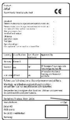
natural_image
Architectural cross-section diagram showing structural layers and ventilation duct (no text or labels)text_image
Technical diagram showing cross-sectional views of a mechanical or structural component with labeled dimensions and features.natural_image
Architectural cross-section diagram showing room layouts and structural elements (no text or labels)natural_image
Architectural line drawing of a building facade with vertical supports and horizontal beams (no text or symbols)3.7 Stalen schoorsteen
natural_image
Technical line drawing of a mechanical assembly with no visible text or symbolsnatural_image
Technical line drawing of a mechanical assembly with no visible text or symbolstext_image
Technical diagram of a mechanical component with labeled parts A and a warning symbolnatural_image
Technical line drawing of a mechanical component with a central lever and flange (no text or symbols)text_image
Technical diagram of a mechanical device with labeled parts A and B, showing internal components and structural details.natural_image
Technical line drawing of a mechanical component with internal cavity and mounting holes (no text or symbols)natural_image
Technical line drawing of a mechanical component with mounting holes and fasteners (no text or symbols)natural_image
Technical diagram of a mechanical assembly with cross-sectional views and labeled component A (no text or symbols present)natural_image
Technical diagram of a mechanical device with labeled component A, showing internal components and directional arrows (no text or symbols beyond labels)natural_image
Technical line drawing of a mechanical component with internal flow arrows (no text or symbols)Quality control of stoves and fireplaces
Jøtul pursue a policy of constant product development. Products supplied may therefore differ in specification, colour and type of accessories from those illustrated and described in the manual.
Kvalitet
Jøtul AS has a quality system that conforms to NS-EN ISO 9001 for product development, manufacturing, and distribution of stoves and fireplaces. This policy gives our customers quality and safety piece of mind as a result of Jøtul's vast experience dating back to when the company first started in 1853.

Jøtul AS,
P.o. box 1411
N-1602 Fredrikstad,
Norway
www.jotul.com