S71 - Fireplace Jøtul - Free user manual and instructions
Find the device manual for free S71 Jøtul in PDF.
User questions about S71 Jøtul
0 question about this device. Answer the ones you know or ask your own.
Ask a new question about this device
Download the instructions for your Fireplace in PDF format for free! Find your manual S71 - Jøtul and take your electronic device back in hand. On this page are published all the documents necessary for the use of your device. S71 by Jøtul.
USER MANUAL S71 Jøtul
natural_image
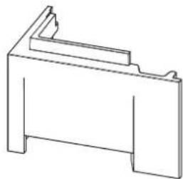
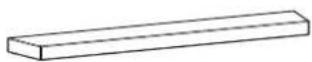
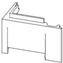
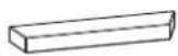
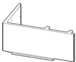
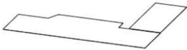
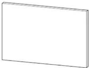
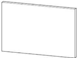
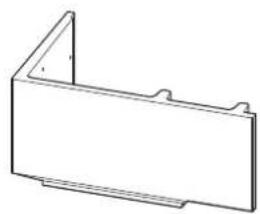
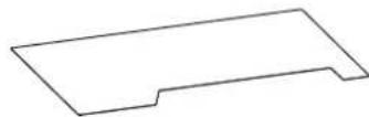
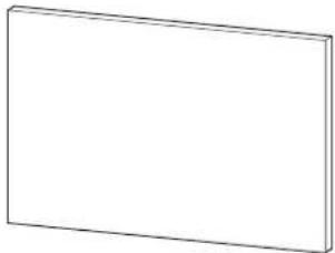
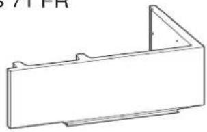
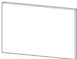
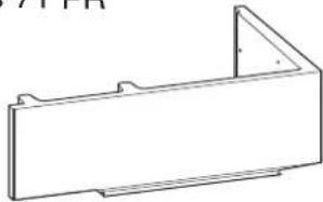
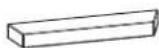
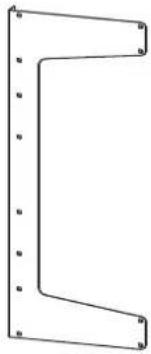
Simple line drawing of a rectangular frame with corner holes (no text or symbols)D 1 stk (Art.nr 50047219)
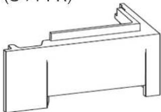
(S 71 FR)

natural_image
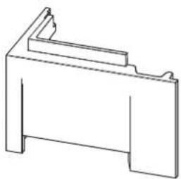
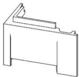
Technical line drawing of a mechanical bracket or housing (no text or symbols)natural_image
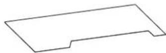
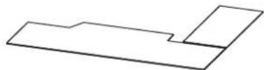
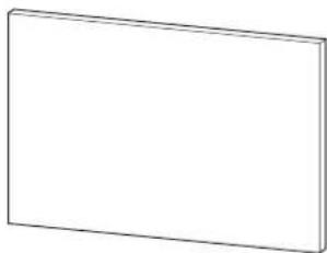
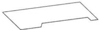
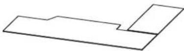
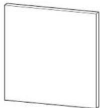
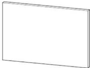
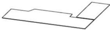
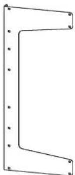
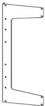
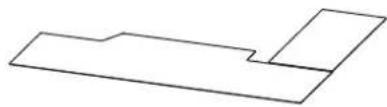
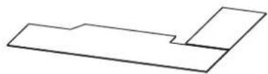
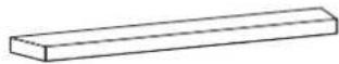
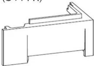
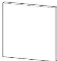
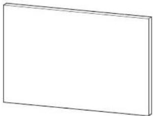
Simple line drawing of a rectangular frame with two side notches (no text or symbols)L 1 stk (Art.nr 10047235)

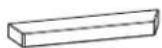
M 1 stk (Art.nr 10047236)
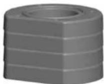
S 2 stk (Art.nr 10047330)
natural_image
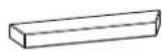
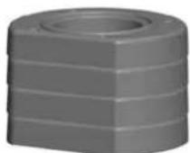
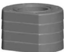
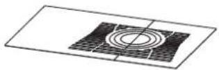
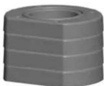
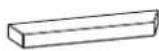
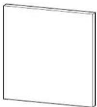
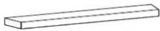
Simple 3D rectangular block diagram with no text or symbolsT 2 stk (Art.nr 10047329)
natural_image
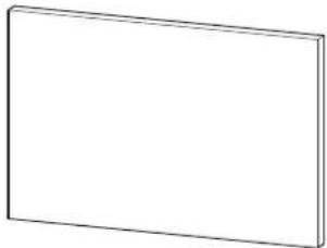
Simple 3D rectangular block diagram with no text, numbers, or symbolsU 5 stk (Art.nr 10047332)

W 2 stk (Art.nr 10047328)

natural_image
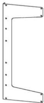
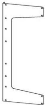
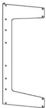
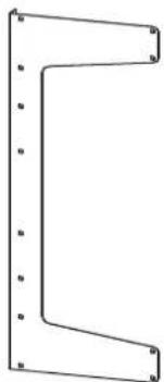
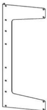
Pure geometric line drawing of a vertical L-shaped structure with evenly spaced dots (no text or symbols)Fig.1b
S 71
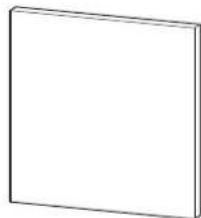
Y 1 stk (Art.nr 10047333)
ZA 22 stk (Gipsskrue _PH2)
ZB 22 stk (Art.nr 10023662)
ZC 8 stk (Gipsskrue 39x25)

S 72
1 stk (Art.nr 50047348)
(S 72 FL)
natural_image
Simple line drawing of a rectangular metal bracket with mounting holes (no text or symbols)J 1 stk (Art.nr 50047347)
(S 72 FL)
natural_image
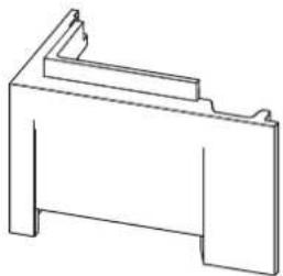
Technical line drawing of a mechanical bracket or housing (no text or symbols)Eklstrautstyr - S 71 & S 72
X 1 stk (Art.nr 10047361)
(Bunnplate)
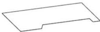
1 stk
(Art.nr 51047337 NO/SE/FI)
(Art.nr 51046304 DE)
(Gulvplate, stål, front)

natural_image
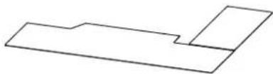
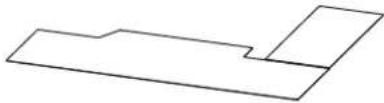
Abstract geometric shape composed of two connected polygons (no text or symbols)1 stk
(Art.nr 50047339 NO/SE/FI)
(Art.nr 50047517 DE)
(Gulvplate, glass, side)
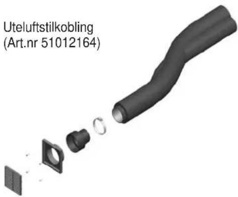
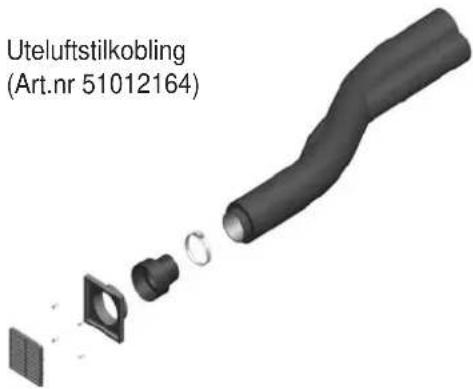
Uteluftstilkobling
(Art.nr 51012164)

text_image
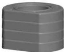
Uteluftstilkobling (Art.nr 51012164)Varmelagrende stein system
(Art.nr 10026701)
NB! Dersom varmelagrende stein skal benyttes när ovnen er montertpå tregulv, er forsterkning av gulvet nødvendig grunnet vektbelastning.
Norsk
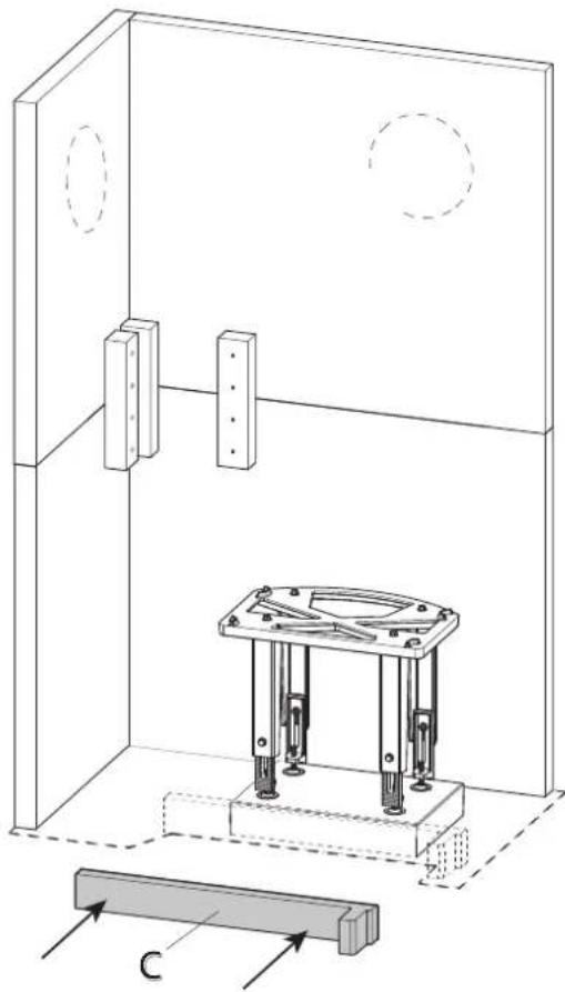
Fig.1c
natural_image
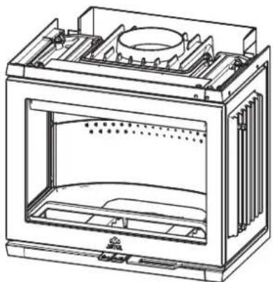
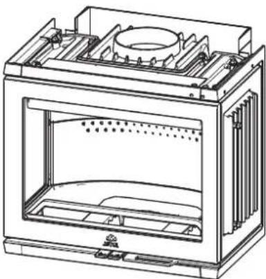
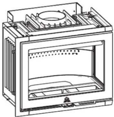
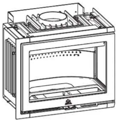
Technical line drawing of a mechanical support structure with four vertical legs and mounting feet (no text or symbols)P 1 stk (Art.nr 30044745)
(I 520 FR for S71)
natural_image
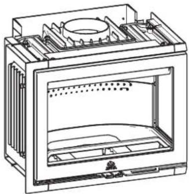
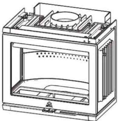
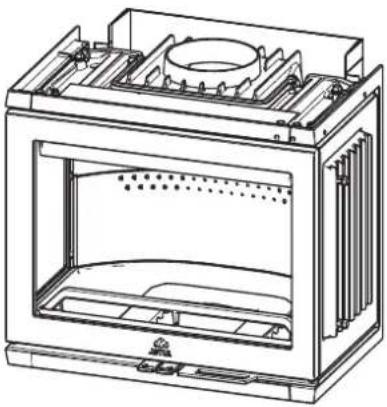
Technical line drawing of a rectangular electronic device with internal compartments and mounting holes (no text or symbols)Q 1 stk (Art.nr 30044744
(I 520 FL for S72)
natural_image
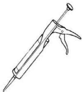
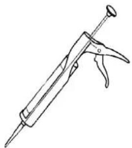
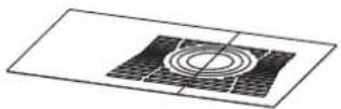
Technical line drawing of a rectangular industrial or laboratory device with internal compartments and a central circular component (no text or symbols)Sementsparkel
Akrylmasse

natural_image
Line drawing of a syringe or applicator tool (no text or symbols)Fig.2
min. avstand til møbler / Brennbart materiale:
1000 mm
900174
Brennbar vegg
Norsk
Fig.3
text_image
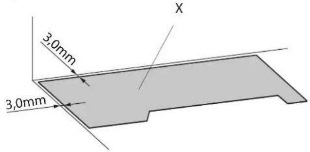
3,0mm 3,0mm Xtext_image
S T S ZA Tnatural_image
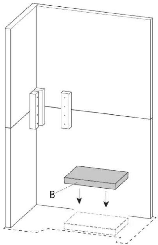
Diagram of a 3D box setup with two vertical supports and a rectangular block labeled B, showing internal force arrows (no text or symbols beyond labels)Fig.9

text_image
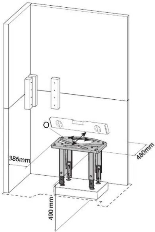
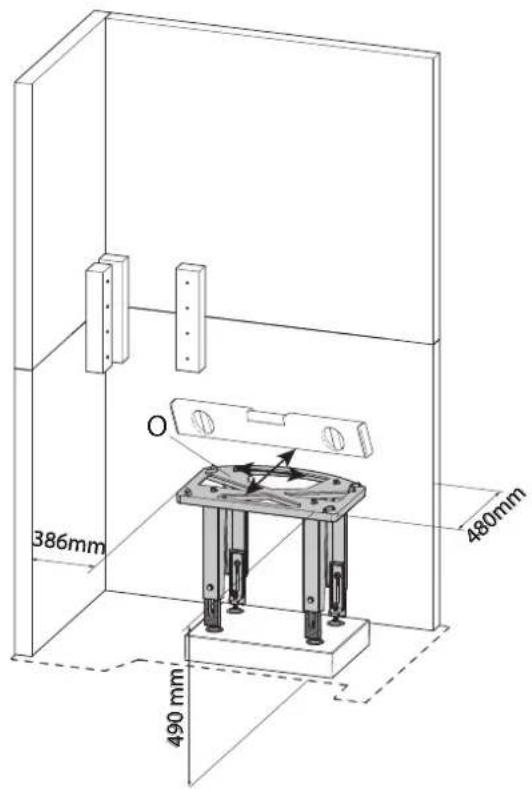
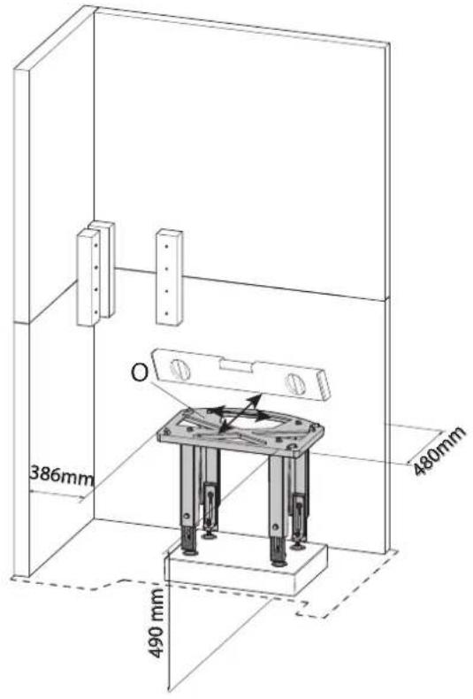
386mm 490 mm 480mmFig.8
text_image
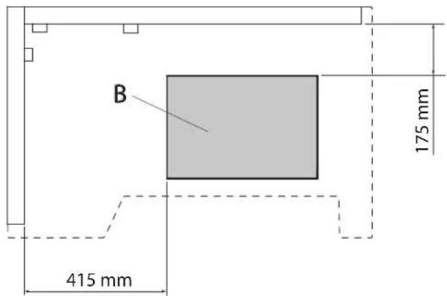
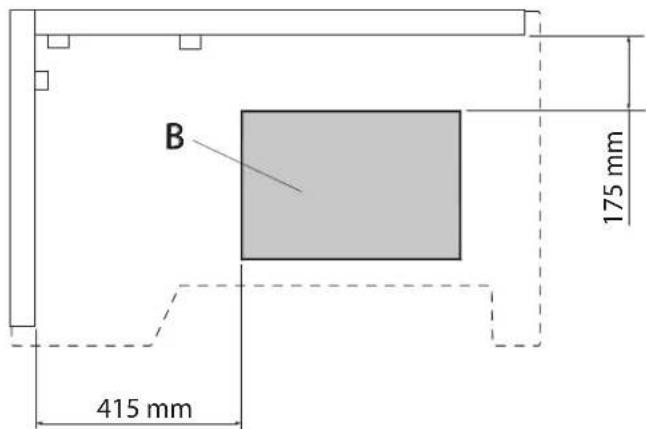
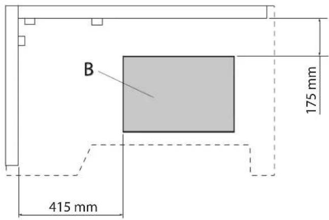
B 415 mm 175 mmFig.10
natural_image
Technical line drawing of a mechanical testing setup with a central platform and two circular components, no text or symbols present.Norsk
Fig.11
text_image
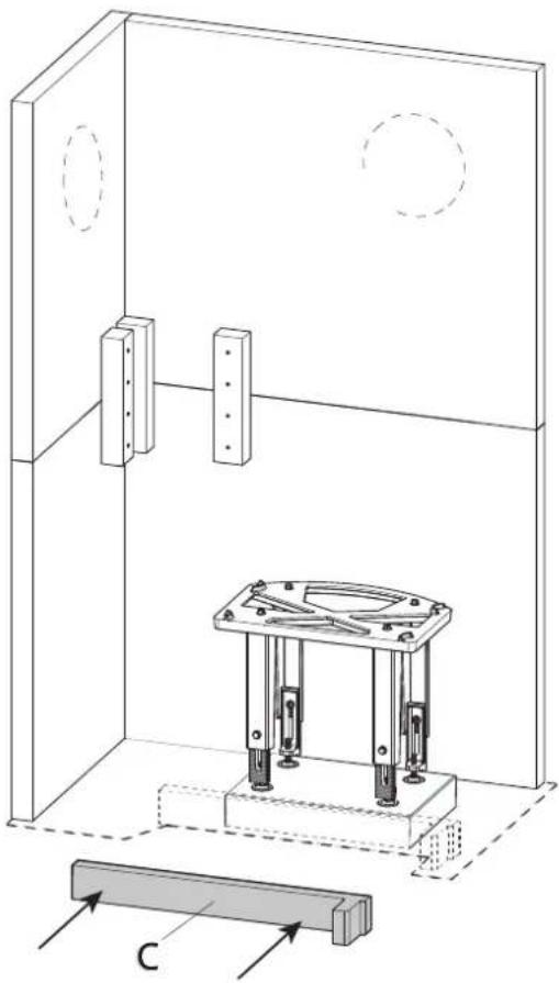
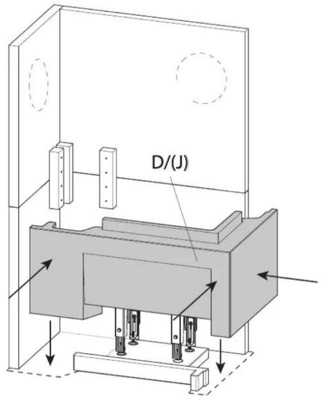
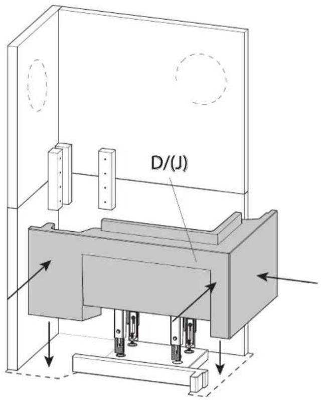
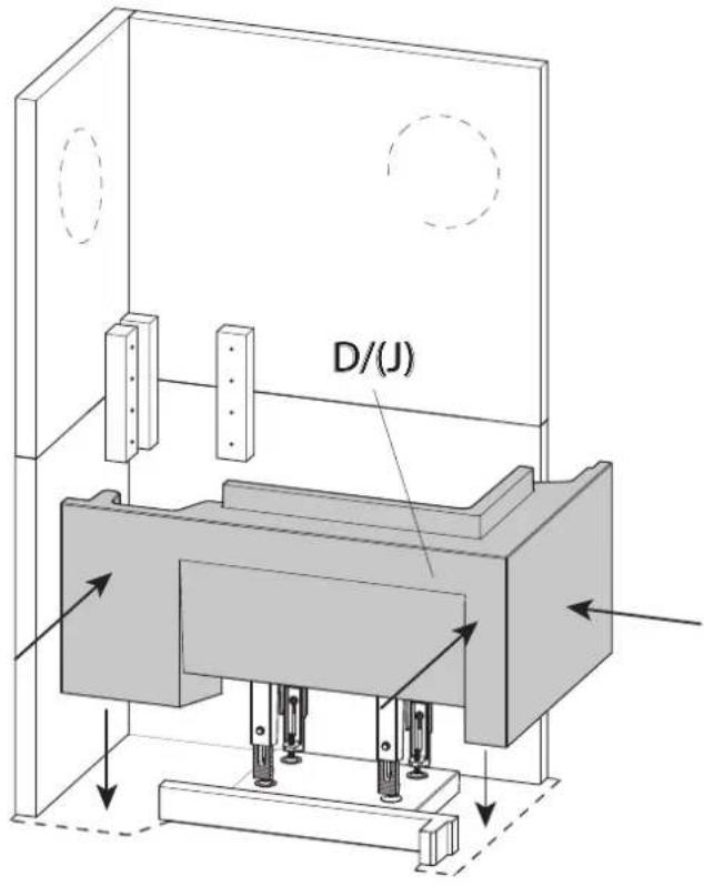
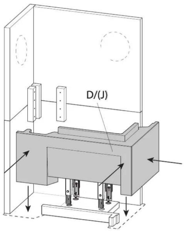
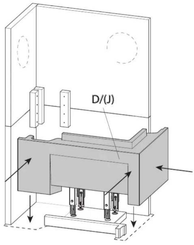
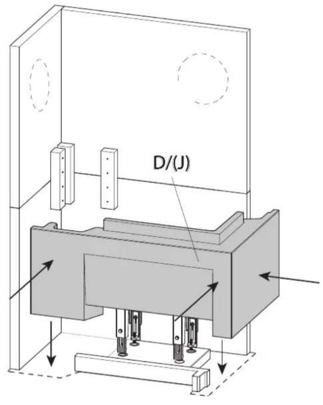
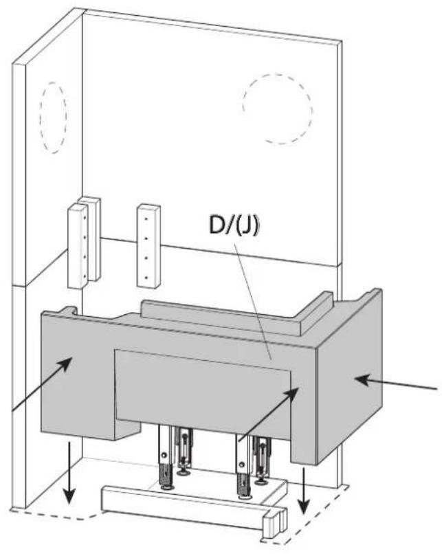
D/(J)Fig.12

text_image
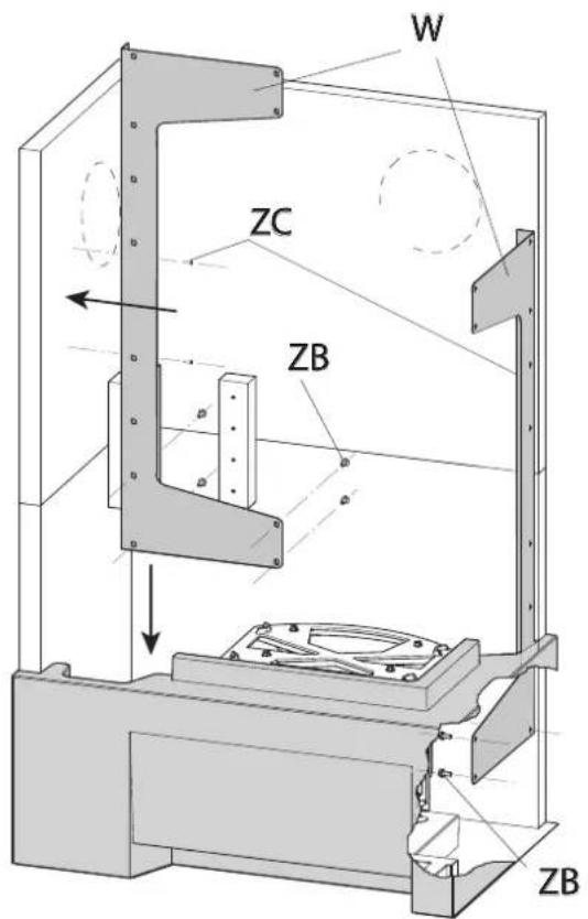
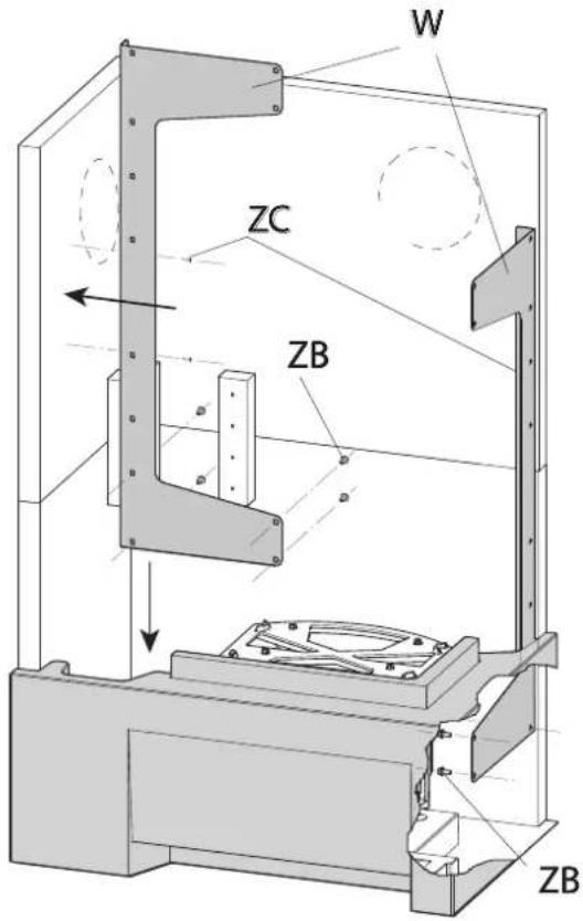
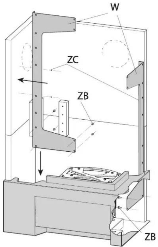
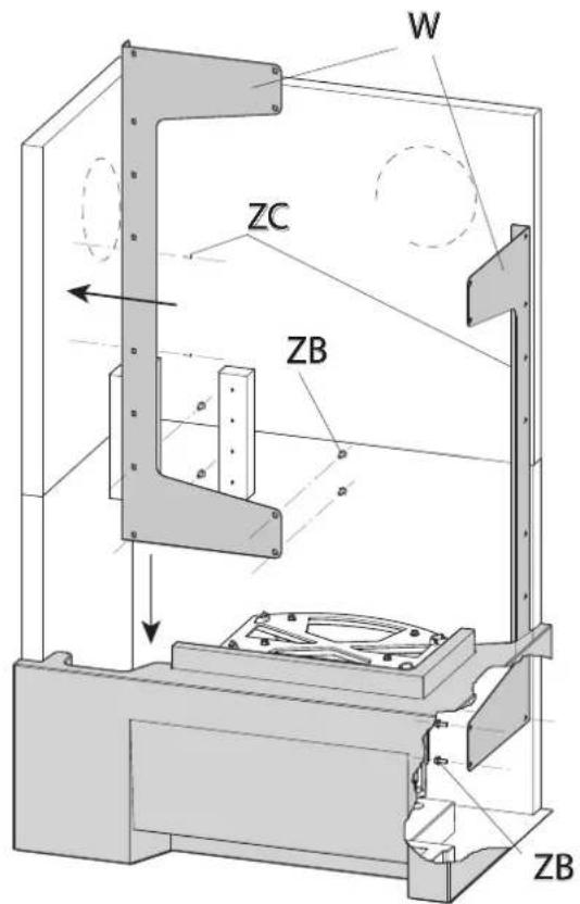
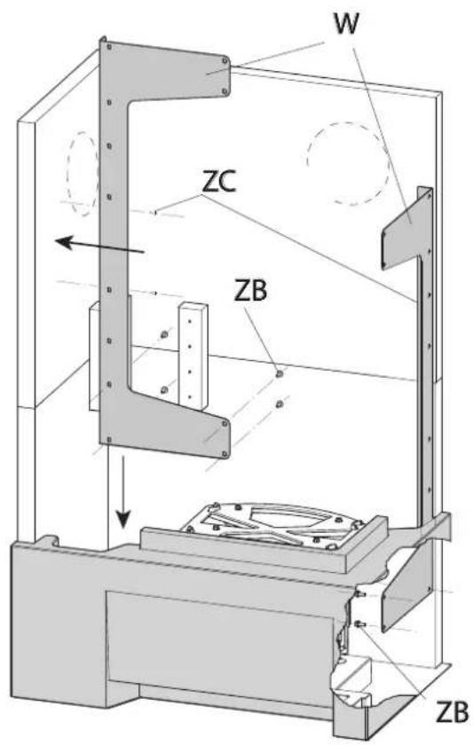
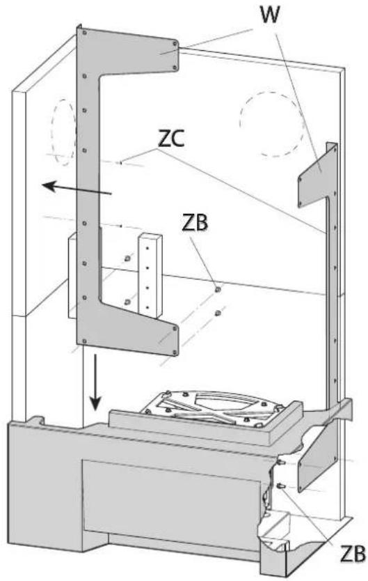
W ZC ZB ZBFig.13
text_image
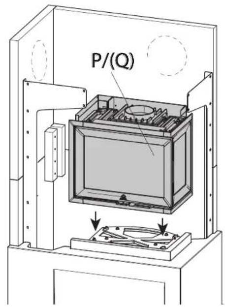
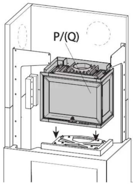
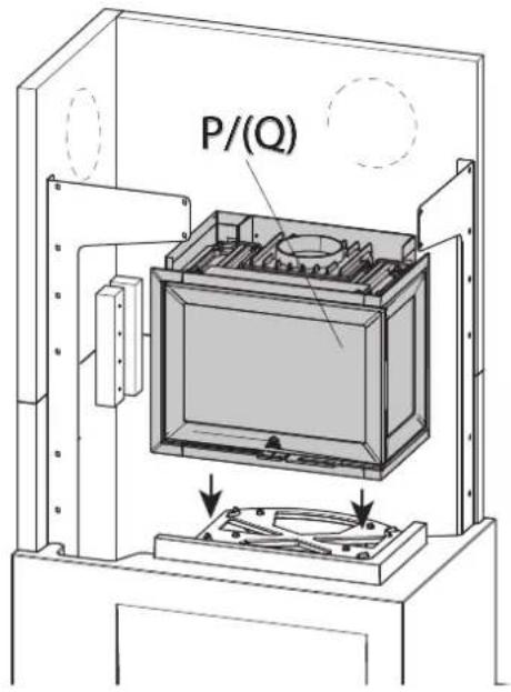
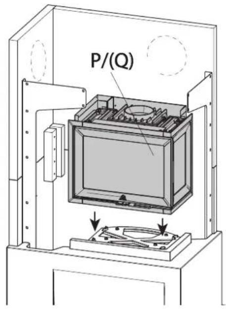
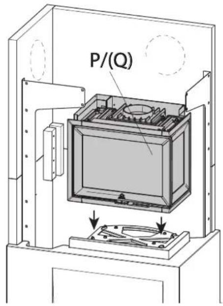
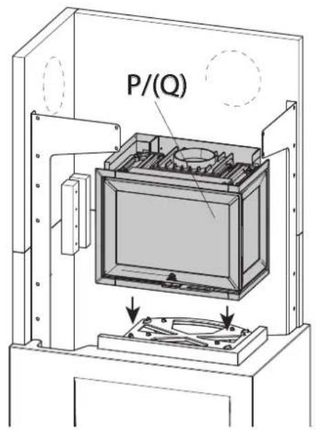
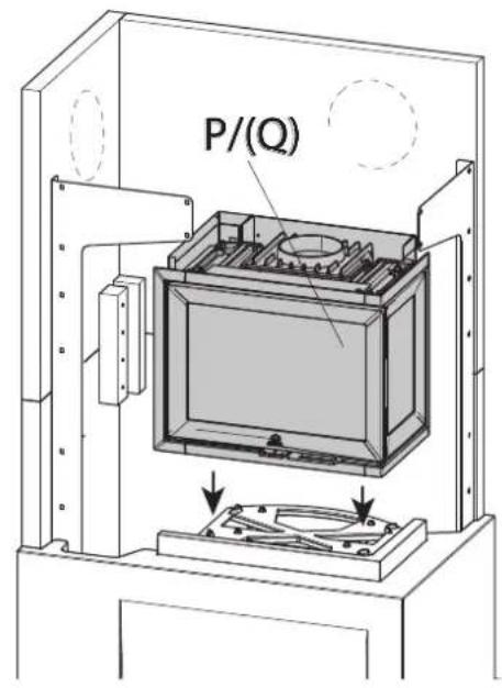
P/(Q)Fig.14
text_image
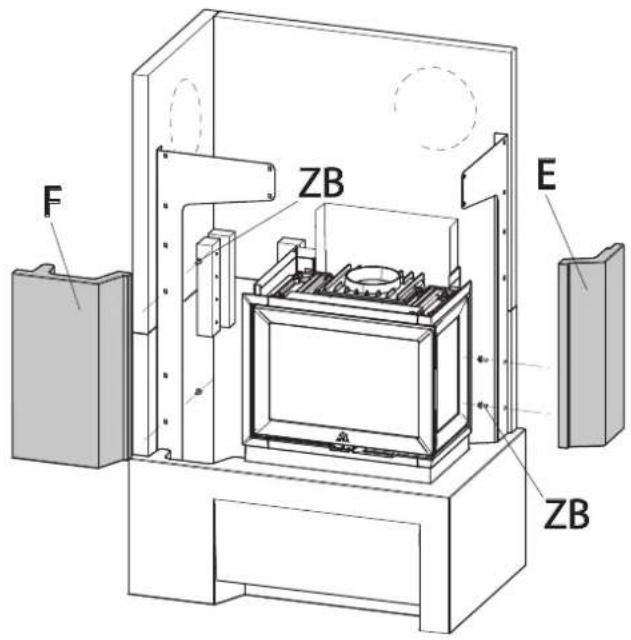
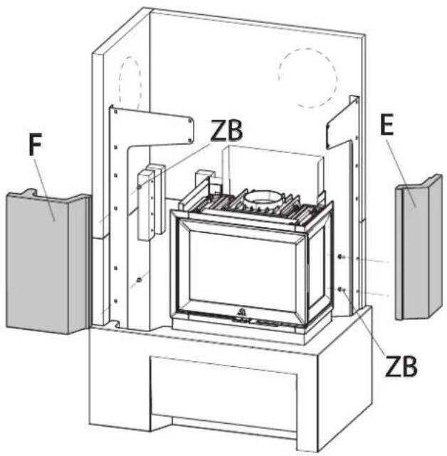
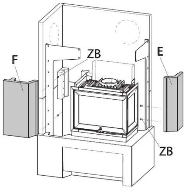
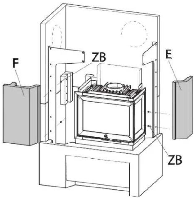
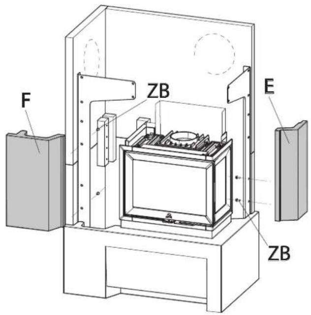
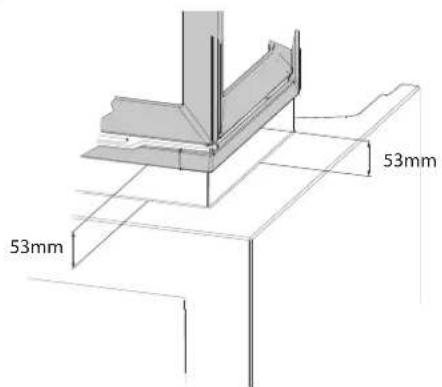
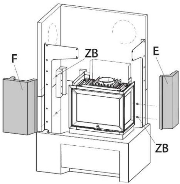
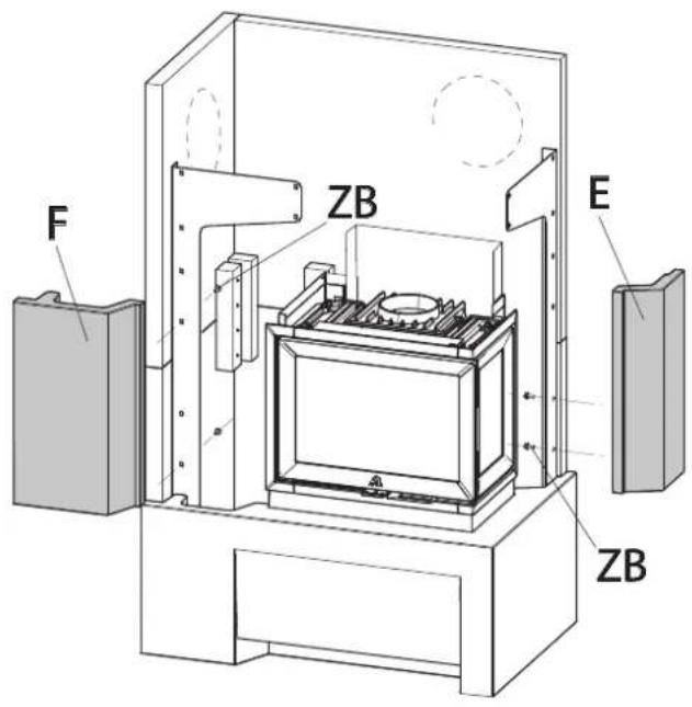
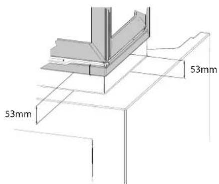
F ZB E ZBFig.14-b

text_image
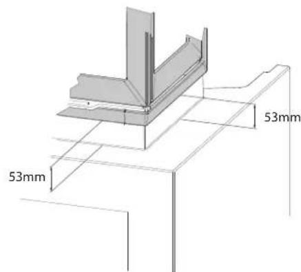
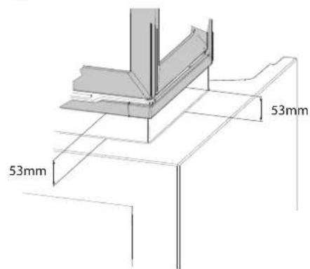
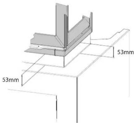
53mm 53mmFig.15
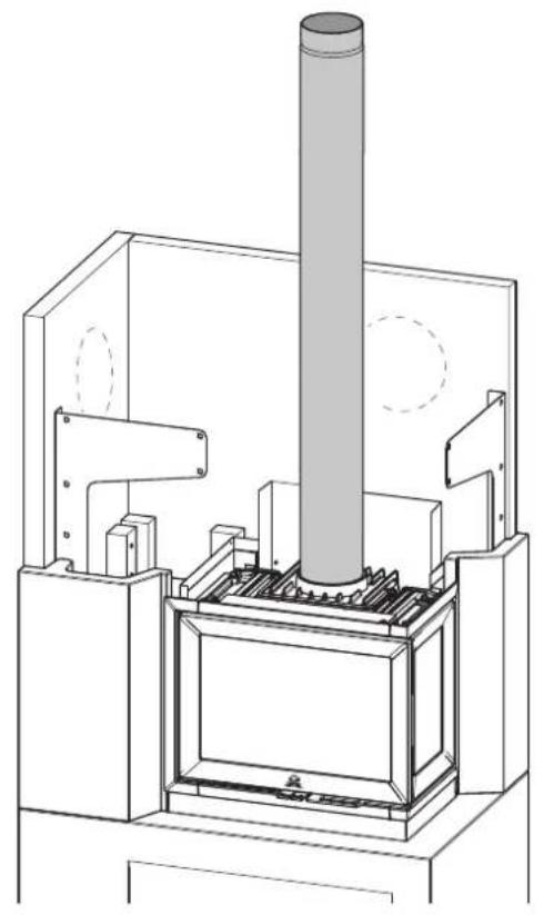
natural_image
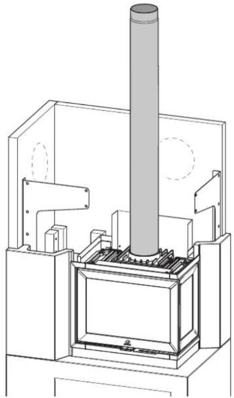
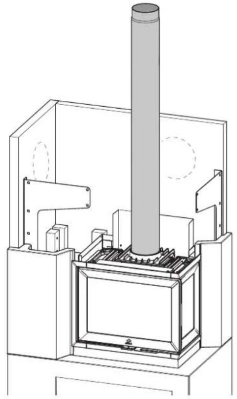
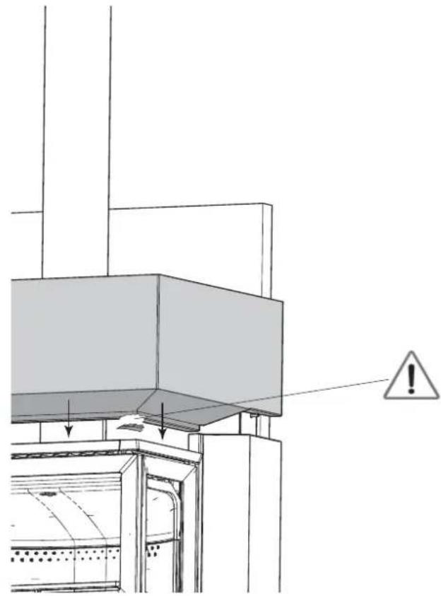
Technical line drawing of a mechanical device with a cylindrical component and internal components (no text or symbols)Fig.16-b

natural_image
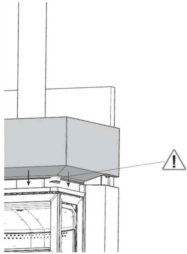
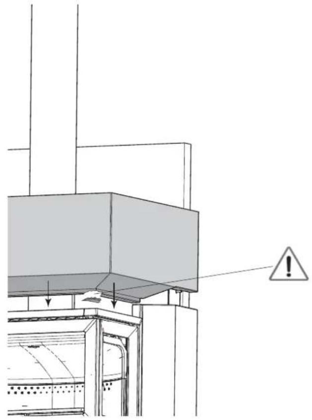
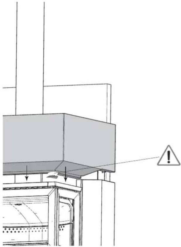
Technical diagram of a structural assembly with warning symbol and arrows indicating components (no readable text or labels)Fig.16
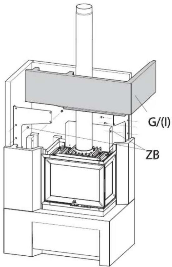
text_image
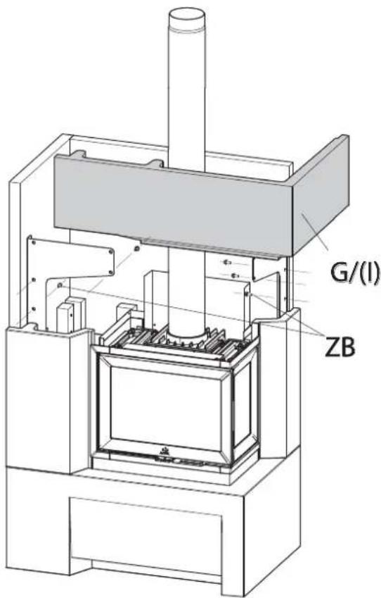
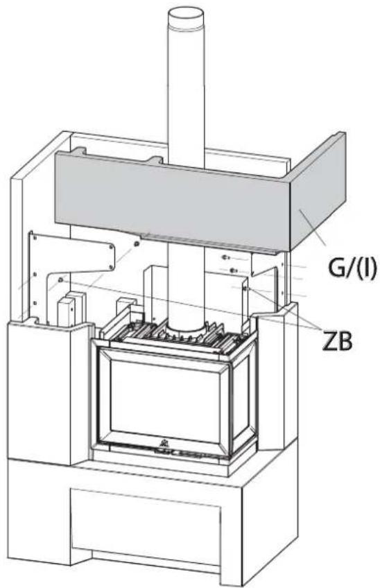
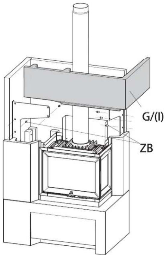
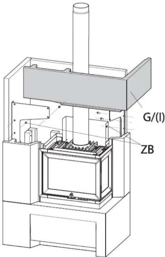
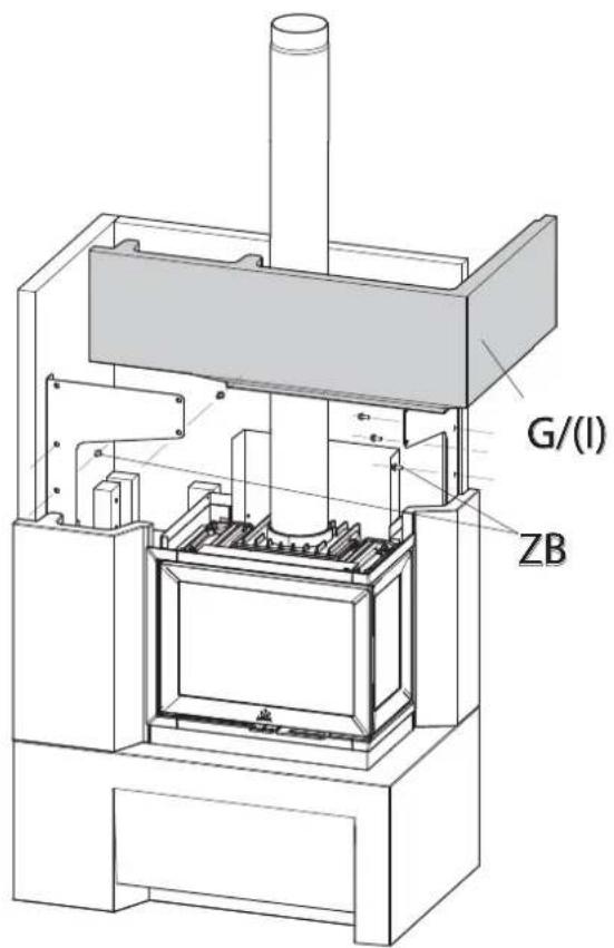
G/(I) ZBFig.17

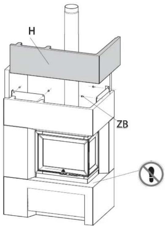
text_image
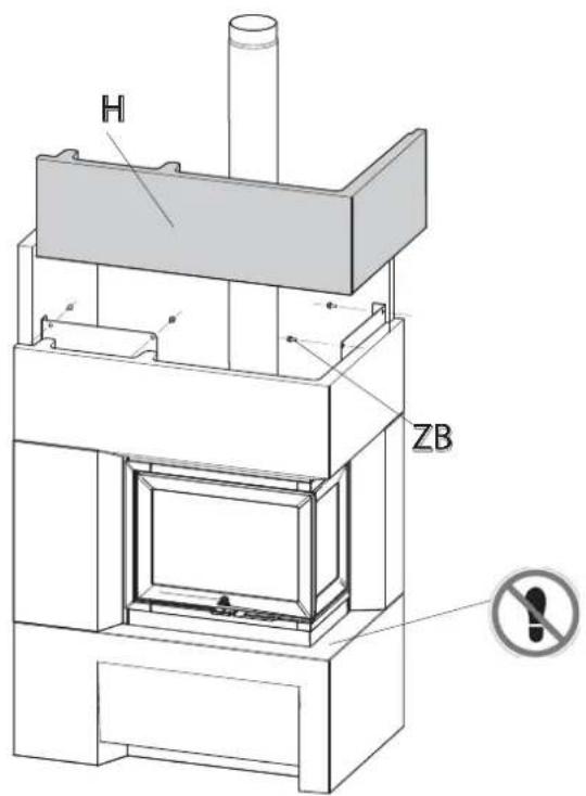
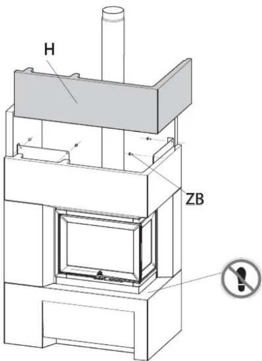
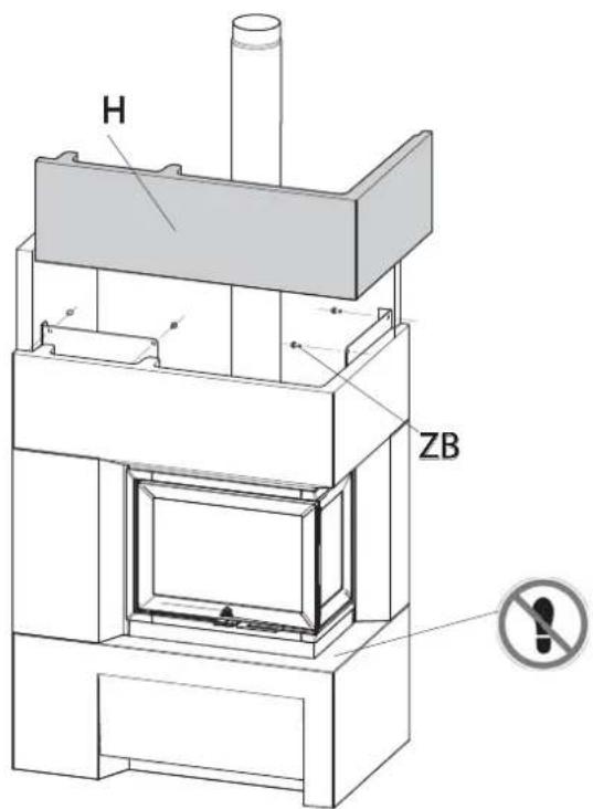
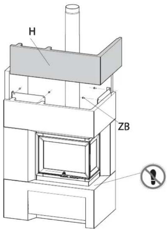
H ZBNorsk
Fig.18

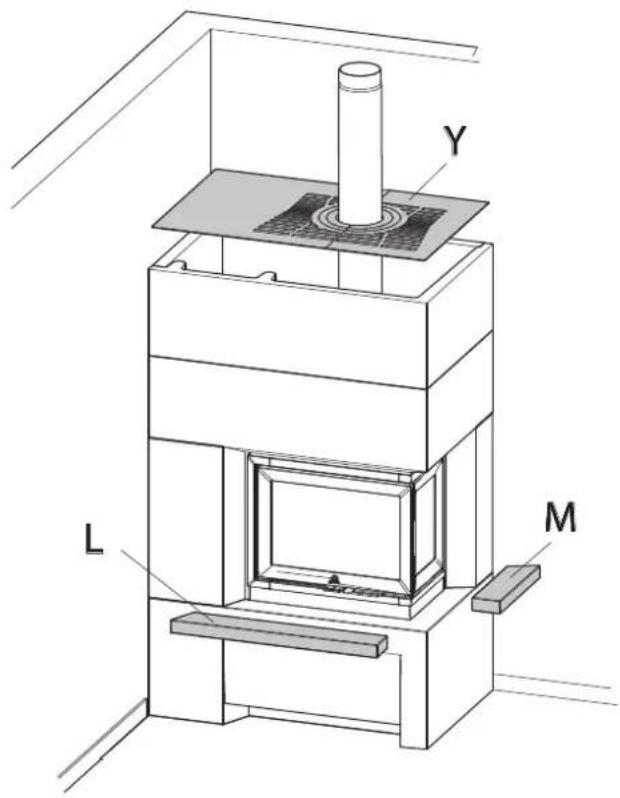
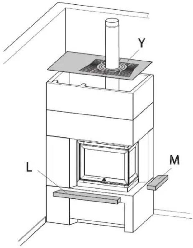
text_image
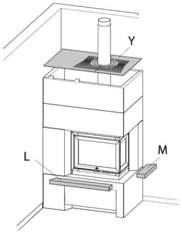
Y L Mnatural_image
Technical line drawing of a rectangular frame with mounting holes (no text or symbols)D 1 stk (Art.nr 50047219)
(S 71 FR)

natural_image
Pure technical line drawing of a mechanical bracket or housing (no text or symbols)natural_image
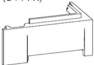
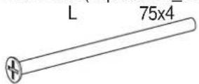
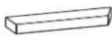
Simple line drawing of a rectangular frame with a corner slot (no text or symbols)L 1 stk (Art.nr 10047235)
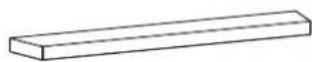
M 1 stk (Art.nr 10047236)
S 2 stk (Art.nr 10047330)

natural_image
Simple 3D rectangular block diagram with no text or symbolsT 2 stk (Art.nr 10047329)
natural_image
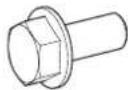
Simple 3D rectangular block diagram with no text, numbers, or symbolsU 5 stk (Art.nr 10047332)

W 2 stk (Art.nr 10047328)
natural_image
Pure geometric line drawing of a V-shaped structure with mounting holes (no text or symbols)SVENSKA
Fig.1b
S 71
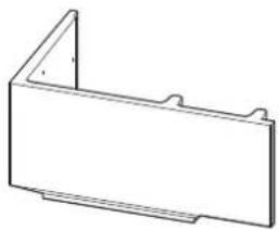
Y 1 stk (Art.nr 10047333)
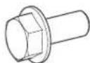
ZA 22 stk (Gipsskrue _PH2)
ZB 22 stk (Art.nr 10023662)
ZC 8 stk (Gipsskrue 39x25)

S 72
I 1 stk (Art.nr 50047348)
(S 72 FL)
natural_image
Simple line drawing of a rectangular metal bracket with notches (no text or symbols)J 1 stk (Art.nr 50047347)
(S 72 FL)
natural_image
Technical line drawing of a mechanical bracket or mounting plate (no text or symbols)Eklstrautstyr - S 71 & S 72
X 1 stk (Art.nr 10047361)
(Bunnplate)
1 stk
(Art.nr 51047337 NO/SE/FI)
(Art.nr 51046304 DE)
(Gulvplate, stål, front)

natural_image
Simple line drawing of two overlapping rectangular shapes with no text or symbols1 stk
(Art.nr 50047339 NO/SE/FI)
(Art.nr 50047517 DE)
(Gulvplate, glass, side)
natural_image
Abstract geometric shape composed of two connected rectangles (no text or symbols)Uteluftstilkobling
(Art.nr 51012164)

text_image
Uteluftstilkobling (Art.nr 51012164)Varmelagrende stein system
(Art.nr 10026701)
NB! Dersom varmelagrende stein skal benyttes när ovnen er montertpå tregulv, er forsterkning av gulvet nødvendig grunnet vektbelastning.
Fig.1c
natural_image
Technical line drawing of a mechanical support structure with four vertical legs and mounting holes (no text or symbols)P 1 stk (Art.nr 30044745)
(I 520 FR for S71)
natural_image
Technical line drawing of a rectangular appliance with internal compartments and ventilation slots (no text or symbols)Q 1 stk (Art.nr 30044744
(I 520 FL for S72)

natural_image
Technical line drawing of a multi-chamber electric stove or cooling unit (no text or symbols)Sementsparkel

Akrylmasse
natural_image
Line drawing of a syringe or applicator tool (no text or symbols)Bild.2
text_image
3,0mm 3,0mm Xtext_image
S T S ZA Tnatural_image
Diagram of a mechanical setup with two vertical supports and a rectangular block, showing force direction arrows (no text or symbols)Bild.9

text_image
386mm 490 mm 480mmBild.8

text_image
B 415 mm 175 mmBild.10

natural_image
Technical line drawing of a mechanical testing setup with a central platform and two vertical supports, enclosed in a rectangular enclosure (no text or symbols)Bild.11
text_image
D/(J)Bild.13
text_image
P/(Q)Bild.12
text_image
W ZC ZB ZBBild.14
text_image
F ZB E ZBBild.14-b

text_image
53mm 53mmSVENSKA
Bild.15
natural_image
Technical line drawing of a mechanical device with a cylindrical component and internal components (no text or symbols)Bild.16-b
natural_image
Technical diagram of a mechanical assembly with warning symbol and arrows indicating components (no readable text or labels)Bild.16

text_image
G/(I) ZBBild.17
text_image
H a a' ZBBild.18
text_image
Y L Mnatural_image
Technical line drawing of a rectangular metal bracket with mounting holes (no text or symbols)D 1 stk (Art.nr 50047219)
(S 71 FR)
natural_image
Technical line drawing of a mechanical bracket or bracket (no text or symbols)natural_image
Simple line drawing of a rectangular frame with two side notches (no text or symbols)L 1 stk (Art.nr 10047235)
M 1 stk (Art.nr 10047236)
S 2 stk (Art.nr 10047330)
natural_image
Simple 3D rectangular block diagram with no text or symbolsT 2 stk (Art.nr 10047329)
natural_image
Simple 3D rectangular block diagram with no text, numbers, or symbolsU 5 stk (Art.nr 10047332)

W 2 stk (Art.nr 10047328)
natural_image
Pure geometric line drawing of a vertical L-shaped structure with evenly spaced dots (no text or symbols)Fig.1b
S 71
Y 1 stk (Art.nr 10047333)
ZA 22 stk (Gipsskrue _PH2)

ZB 22 stk (Art.nr 10023662)
ZC 8 stk (Gipsskrue 39x25)

S 72
I 1 stk (Art.nr 50047348)
(S 72 FL)
natural_image
Simple line drawing of a rectangular metal bracket with mounting holes (no text or symbols)J 1 stk (Art.nr 50047347)
(S 72 FL)
natural_image
Technical line drawing of a mechanical bracket or bracket (no text or symbols)Eklstrautstyr - S 71 & S 72
X 1 stk (Art.nr 10047361)
(Bunnplate)

1 stk
(Art.nr 51047337 NO/SE/FI)
(Art.nr 51046304 DE)
(Gulvplate, stål, front)
natural_image
Abstract geometric shape composed of two connected polygons (no text or symbols)1 stk
(Art.nr 50047339 NO/SE/FI)
(Art.nr 50047517 DE)
(Gulvplate, glass, side)
Uteluftstilkobling
(Art.nr 51012164)

text_image
Uteluftstilkobling (Art.nr 51012164)Varmelagrende stein system
(Art.nr 10026701)
natural_image
Technical line drawing of a mechanical support structure with four vertical legs and mounting holes (no text or symbols)P 1 stk (Art.nr 30044745)
(I 520 FR for S71)

natural_image
Technical line drawing of a rectangular appliance with internal compartments and mounting feet (no text or symbols)Q 1 stk (Art.nr 30044744
(I 520 FL for S72)
natural_image
Technical line drawing of a multi-chamber electric stove or cooling unit (no text or symbols)Sementsparkel

Akrylmasse
natural_image
Line drawing of a syringe or spray gun (no text or symbols)text_image
3,0mm 3,0mm Xtext_image
S T S ZA Tnatural_image
Diagram of a 3D box setup with two vertical supports and a rectangular block, labeled B, showing internal force or displacement (no text or symbols beyond labels)Fig.9
text_image
386mm 490 mm 480mmFig.8

text_image
B 415 mm 175 mmFig.10

natural_image
Technical line drawing of a mechanical testing setup with a central platform and two circular components, no text or symbols present.DANSK
Fig.11
text_image
D/(J)Fig.12
text_image
ZC W ZB ZBFig.13
text_image
P/(Q)Fig.14
text_image
F ZB E ZBFig.14-b
text_image
53mm 53mmFig.15
natural_image
Technical line drawing of a mechanical device with a cylindrical component and internal components (no text or symbols)Fig.16-b

natural_image
Technical line drawing of a mechanical assembly with warning symbol (no text or labels)Fig.16

text_image
G/(I) ZBFig.17
text_image
H ZBDANSK
Fig.18

text_image
Y L Mnatural_image
Simple line drawing of a rectangular frame with corner holes (no text or symbols)D 1 stk (Art.nr 50047219)
(S 71 FR)

natural_image
Technical line drawing of a mechanical bracket or housing (no text or symbols)natural_image
Simple line drawing of a rectangular frame with a corner slot (no text or symbols)L 1 stk (Art.nr 10047235)
M 1 stk (Art.nr 10047236)
S 2 stk (Art.nr 10047330)
natural_image
Simple 3D rectangular block diagram with no text or symbolsT 2 stk (Art.nr 10047329)
natural_image
Simple 3D rectangular block diagram with no text, numbers, or symbolsU 5 stk (Art.nr 10047332)

W 2 stk (Art.nr 10047328)
natural_image
Pure geometric line drawing of a vertical U-shaped structure with evenly spaced dots (no text or symbols)Fig.1b
S 71
Y 1 stk (Art.nr 10047333)
ZA 22 stk (Gipsskrue _PH2)
ZB 22 stk (Art.nr 10023662)
ZC 8 stk (Gipsskrue 39x25)

S 72
I 1 stk (Art.nr 50047348)
(S 72 FL)
natural_image
Simple line drawing of a rectangular metal bracket with notches (no text or symbols)J 1 stk (Art.nr 50047347)
(S 72 FL)
natural_image
Technical line drawing of a mechanical bracket or housing (no text or symbols)Eklstrautstyr - S 71 & S 72
X 1 stk (Art.nr 10047361)
(Bunnplate)
1 stk
(Art.nr 51047337 NO/SE/FI)
(Art.nr 51046304 DE)
(Gulvplate, stål, front)
natural_image
Abstract geometric shape composed of two connected rectangles (no text or symbols)1 stk
(Art.nr 50047339 NO/SE/FI)
(Art.nr 50047517 DE)
(Gulvplate, glass, side)


text_image
Uteluftstilkobling (Art.nr 51012164)Varmelagrende stein system
(Art.nr 10026701)
NB! Dersom varmelagrende stein skal benyttes när ovnen er montertpå tregulv, er forsterkning av gulvet nødvendig grunnet vektbelastning.
SUOMI
Fig.1c
natural_image
Technical line drawing of a mechanical support base with four vertical legs and mounting holes (no text or symbols)P 1 stk (Art.nr 30044745)
(I 520 FR for S71)
natural_image
Technical line drawing of a rectangular electronic device with internal compartments and mounting holes (no text or symbols)Q 1 stk (Art.nr 30044744
(I 520 FL for S72)
natural_image
Technical line drawing of a rectangular industrial or laboratory device with internal compartments and mounting brackets (no text or symbols)Sementsparkel
Akrylmasse
natural_image
Line drawing of a syringe or applicator tool (no text or symbols)text_image
S T S ZA THUOM: Vaihda levyt (T), jos asennat takkasydämen Jøtul S72 (Jøtul I520FL sijaan)
Kuva.5
text_image
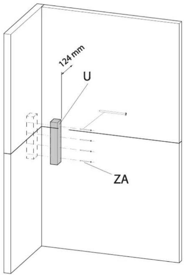
124 mm U ZAKuva 6
text_image
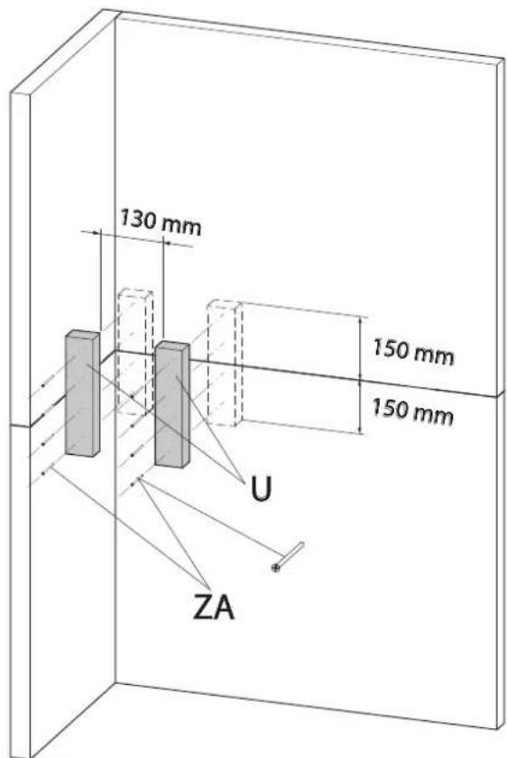
130 mm 150 mm 150 mm U ZAKuva.7
natural_image
Diagram of a 3D box setup with two vertical supports and a rectangular block labeled B, showing internal force arrows (no text or symbols beyond labels)Kuva.9
text_image
386mm 490 mm 480mmKuva.8

text_image
B 415 mm 175 mmKuva.10

natural_image
Technical line drawing of a mechanical testing setup with a central platform and two vertical supports, enclosed in a cabinet (no text or symbols)SUOMI
Kuva.11
text_image
D/(J)Kuva.13
text_image
P/(Q)Kuva.12
text_image
W ZC ZB ZBKuva.14
text_image
F ZB E ZBKuva.14-b
text_image
53mm 53mmKuva.15
natural_image
Technical line drawing of a mechanical device with a cylindrical component mounted on a base frame (no text or symbols visible)Kuva.16-b
natural_image
Technical diagram of a structural assembly with warning symbol and arrows indicating components (no readable text or labels)Kuva.16
text_image
G/(I) ZBKuva.17

text_image
H ZBSUOMI
Kuva.18

text_image
Y L Mnatural_image
Line drawing of a rectangular metal bracket with mounting holes (no text or symbols)D 1 stk (Art.nr 50047219)
(S 71 FR)

natural_image
Pure technical line drawing of a mechanical bracket or housing (no text or symbols)natural_image
Simple line drawing of a rectangular frame with two side notches (no text or symbols)L 1 stk (Art.nr 10047235)

M 1 stk (Art.nr 10047236)

S 2 stk (Art.nr 10047330)

natural_image
Simple 3D rectangular block with no text or symbolsT 2 stk (Art.nr 10047329)
natural_image
Simple 3D rectangular block diagram with no text, numbers, or symbolsU 5 stk (Art.nr 10047332)

W 2 stk (Art.nr 10047328)
natural_image
Pure geometric line drawing of a vertical U-shaped structure with evenly spaced dots (no text or symbols)S 71
Y 1 stk (Art.nr 10047333)
ZA 22 stk (Gipsskrue _PH2)

ZB 22 stk (Art.nr 10023662)
ZC 8 stk (Gipsskrue 39x25)

S 72
I 1 stk (Art.nr 50047348) (S 72 FL)
natural_image
Simple line drawing of a rectangular frame with mounting holes (no text or symbols)J 1 stk (Art.nr 50047347) (S 72 FL)
natural_image
Technical line drawing of a mechanical bracket or bracket (no text or symbols)Eklstrautstyr - S 71 & S 72
X 1 stk (Art.nr 10047361) (Bunnplate)
1 stk
(Art.nr 51047337 NO/SE/FI)
(Art.nr 51046304 DE)
(Gulvplate, stål, front)
natural_image
Simple line drawing of two overlapping rectangular shapes with no text or symbols1 stk
(Art.nr 50047339 NO/SE/FI)
(Art.nr 50047517 DE)
(Gulvplate, glass, side)
natural_image
Abstract geometric shape composed of two connected polygons (no text or symbols)Uteluftstilkobling
(Art.nr 51012164)
text_image
Uteluftstilkobling (Art.nr 51012164)Varmelagrende stein system (Art.nr 10026701)
natural_image
Technical line drawing of a mechanical support structure with four vertical legs and mounting holes (no text or symbols)P 1 stk (Art.nr 30044745)
(I 520 FR for S71)
natural_image
Technical line drawing of a rectangular industrial or laboratory device with internal compartments and mounting brackets (no text or symbols)Q 1 stk (Art.nr 30044744
(I 520 FL for S72)
natural_image
Technical line drawing of a multi-chamber appliance housing with internal compartments and mounting brackets (no text or symbols)Sementsparkel
Akrylmasse

natural_image
Line drawing of a laboratory pipette or clamp device (no text or symbols)text_image
3,0mm 3,0mm Xtext_image
S T S ZA TRemarque : Inversez les plaques (T) si un Jøtul S72 (pour Jøtul I520FL) est installé
Fig.5

text_image
124 mm U ZAFig 6

text_image
130 mm 150 mm 150 mm U ZAFRANCAIS
Fig.7

natural_image
Diagram of a 3D box setup with two vertical supports and a rectangular block, showing directional arrows (no text or symbols)Fig.9

text_image
386mm 490 mm 480mmFig.8

text_image
B 415 mm 175 mmFig.10

natural_image
Technical line drawing of a mechanical testing setup with a central platform and two vertical supports, enclosed in a rectangular enclosure (no text or symbols)Fig.11
text_image
D/(J)Fig.13
text_image
P/(Q)Fig.12
text_image
W ZC ZB ZBFig.14
text_image
F ZB E ZBFig.14-b
text_image
53mm 53mmFRANCAIS
Fig.15
natural_image
Technical line drawing of a mechanical device with a cylindrical component and internal components (no text or symbols)Fig.16-b

natural_image
Technical diagram of a structural support frame with warning symbol and arrows indicating force or detail (no text labels)Fig.16
text_image
G/(I) ZBFig.17
text_image
H a' a' ZBFig.18

text_image
Y L Mnatural_image
Line drawing of a 3D rectangular frame with mounting holes and a triangular top (no text or symbols)D 1 stk (Art.nr 50047219)
(S 71 FR)
natural_image
Pure technical line drawing of a mechanical bracket or housing (no text or symbols)natural_image
Simple line drawing of a rectangular frame with two side notches and a central hole (no text or symbols)L 1 stk (Art.nr 10047235)

M 1 stk (Art.nr 10047236)
S 2 stk (Art.nr 10047330)

natural_image
Simple 3D rectangular block diagram with no text or symbolsT 2 stk (Art.nr 10047329)
natural_image
Simple 3D rectangular block diagram with no text, numbers, or symbolsU 5 stk (Art.nr 10047332)

W 2 stk (Art.nr 10047328)
natural_image
Pure geometric line drawing of a U-shaped structure with evenly spaced dots (no text or symbols)NEDERLANDS
Fig.1b
S 71
Y 1 stk (Art.nr 10047333)
ZA 22 stk (Gipsskrue _PH2)
ZB 22 stk (Art.nr 10023662)
ZC 8 stk (Gipsskrue 39x25)

S 72
I 1 stk (Art.nr 50047348)
(S 72 FL)
natural_image
Simple line drawing of a rectangular frame with mounting holes (no text or symbols)J 1 stk (Art.nr 50047347)
(S 72 FL)
natural_image
Technical line drawing of a mechanical bracket or bracket (no text or symbols)Eklstrautstyr - S 71 & S 72
X 1 stk (Art.nr 10047361)
(Bunnplate)
1 stk
(Art.nr 51047337 NO/SE/FI)
(Art.nr 51046304 DE)
(Gulvplate, stål, front)
natural_image
Abstract geometric shape composed of two rectangles and a zigzag line (no text or symbols)1 stk
(Art.nr 50047339 NO/SE/FI)
(Art.nr 50047517 DE)
(Gulvplate, glass, side)

Uteluftstilkobling
(Art.nr 51012164)
text_image
Uteluftstilkobling (Art.nr 51012164)Varmelagrende stein system
(Art.nr 10026701)
NB! Dersom varmelagrende stein skal benyttes när ovnen er montertpå tregulv, er forsterkning av gulvet nødvendig grunnet vektbelastning.
Fig.1c
natural_image
Technical line drawing of a mechanical support structure with four vertical legs and mounting holes (no text or symbols)P 1 stk (Art.nr 30044745)
(I 520 FR for S71)
natural_image
Technical line drawing of a rectangular appliance with internal compartments and mounting holes (no text or symbols)Q 1 stk (Art.nr 30044744
(I 520 FL for S72)

natural_image
Technical line drawing of a multi-chamber electric stove or cooling unit (no text or symbols)Sementsparkel

Akrylmasse

natural_image
Line drawing of a syringe or applicator tool (no text or symbols)Fig.2
Minimale hoogte vanaf meubels/ brandbare materialen:
1000 mm
900174
Brandbare muur
Fig.3

text_image
3,0mm 3,0mm Xtext_image
S T S ZA Tnatural_image
Diagram of a rectangular box with two vertical supports and a labeled block B, showing internal force or displacement (no text or symbols beyond labels)Fig.9

text_image
386mm 490 mm 480mmFig.8

text_image
B 415 mm 175 mmFig.10
natural_image
Technical line drawing of a mechanical testing setup with a central platform and two circular components, no text or symbols present.Fig.11
text_image
D/(J)Fig.12
text_image
W ZC ZB ZBFig.13
text_image
P/(Q)Fig.14
text_image
F ZB E ZBFig.14-b

text_image
53mm 53mmNEDERLANDS
Fig.15
natural_image
Technical line drawing of a mechanical device with a cylindrical component and internal components (no text or symbols)Fig.16-b
natural_image
Technical diagram of a ceiling structure with warning symbol and arrows indicating airflow or safety (no text labels)Fig.16
text_image
G/(I) ZBFig.17
text_image
H ZBFig.18
text_image
Y L Mnatural_image
Simple line drawing of a rectangular frame with corner holes (no text or symbols)D 1 stk (Art.nr 50047219)
(S 71 FR)

natural_image
Pure technical line drawing of a mechanical bracket or housing (no text or symbols)natural_image
Simple line drawing of a rectangular frame with two side notches (no text or symbols)L 1 stk (Art.nr 10047235)

M 1 stk (Art.nr 10047236)
S 2 stk (Art.nr 10047330)
natural_image
Simple 3D rectangular block with no text or symbolsT 2 stk (Art.nr 10047329)
natural_image
Simple 3D rectangular block diagram with no text, numbers, or symbolsU 5 stk (Art.nr 10047332)

W 2 stk (Art.nr 10047328)

natural_image
Pure geometric line drawing of a vertical U-shaped structure with evenly spaced dots (no text or symbols)DEUTSCH
Fig.1a
S 71
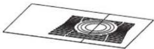
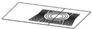
G 1 stk (Art.nr 50047222)
S 71 FR
natural_image
Simple line drawing of a 3D rectangular frame with corner holes (no text or symbols)D 1 stk (Art.nr 50047219)
(S 71 FR)

natural_image
Technical line drawing of a mechanical bracket or housing (no text or symbols)natural_image
Simple line drawing of a rectangular frame with a corner slot (no text or symbols)L 1 stk (Art.nr 10047235)
M 1 stk (Art.nr 10047236)
S 2 stk (Art.nr 10047330)
natural_image
Simple 3D rectangular block with no text or symbolsT 2 stk (Art.nr 10047329)
natural_image
Simple 3D rectangular block diagram with no text or symbolsU 5 stk (Art.nr 10047332)

W 2 stk (Art.nr 10047328)
natural_image
Pure geometric line drawing of a vertical U-shaped structure with evenly spaced dots (no text or symbols)natural_image
Technical line drawing of a four-legged table with four legs and a central handle (no text or symbols)P 1 stk (Art.nr 30044745) (I 520 FR for S71)
natural_image
Technical line drawing of a rectangular appliance with internal compartments and mounting holes (no text or symbols)Q 1 stk (Art.nr 30044744 (I 520 FL for S72)
natural_image
Technical line drawing of a rectangular industrial or laboratory enclosure with internal compartments and mounting brackets (no text or symbols)Sementsparkel
Akrylmasse

natural_image
Line drawing of a syringe or applicator tool (no text or symbols)text_image
3,0mm 3,0mm Xtext_image
S T S ZA Tnatural_image
Diagram of a rectangular block inside a transparent enclosure with two vertical supports and a dashed box, labeled 'B' (no text or symbols on the diagram itself)Abb.9

text_image
386mm 490 mm 480mmAbb.8
text_image
B 415 mm 175 mmAbb.10
natural_image
Technical line drawing of a mechanical testing setup with a central platform and two vertical supports, enclosed in a rectangular enclosure (no text or symbols)Abb.11

text_image
D/(J)Abb.13
text_image
P/(Q)Abb.12

text_image
W ZC ZB ZBAbb.14
text_image
F ZB E ZBAbb.14-b
text_image
53mm 53mmDEUTSCH
Abb.15
natural_image
Technical line drawing of a mechanical device with a cylindrical component and internal components (no text or symbols)Abb.16-b
natural_image
Technical diagram of a mechanical assembly with warning symbol and arrows indicating components (no readable text or labels)Abb.16
text_image
G/(l) ZBAbb.17

text_image
H ZB1.0 Relationship to the Authorities....97
2.0 Technical Data....97
3.0 Safety 97
4.0 Installation 98
5.0 Installation Completed.... 108
6.0 Optional extras 108
7.0 Recycling.... 109
8.0 Warrenty 109
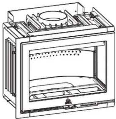
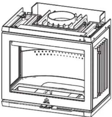
1.0 Relationship to the Authorities
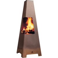
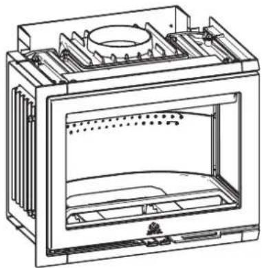
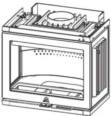
The surround is designed for use with the Jøtul I 520 FR/FL
- Surrounds S71 and S71 are designed for insert Jøtul I 520FR and insert Jøtul I 520FL and are subject to the same setup conditions as applicable to the respective inserts. Before the fi replace can be used, it must be inspected by a qualified inspector. A qualified inspector may be a centrally-approved company or an approved local authority inspection agency. It is always advisable to seek information from your local planning and building offi ce and professional help before starting installation work.
- The insert comes with installation and operating instructions. The product may not be used until it has been inspected and a certificate of completion has been issued. For day-to-day use, maintenance, service work, etc. see the Installation and Operating Instructions for Jøtul I 520 (cat. no. 10044945).
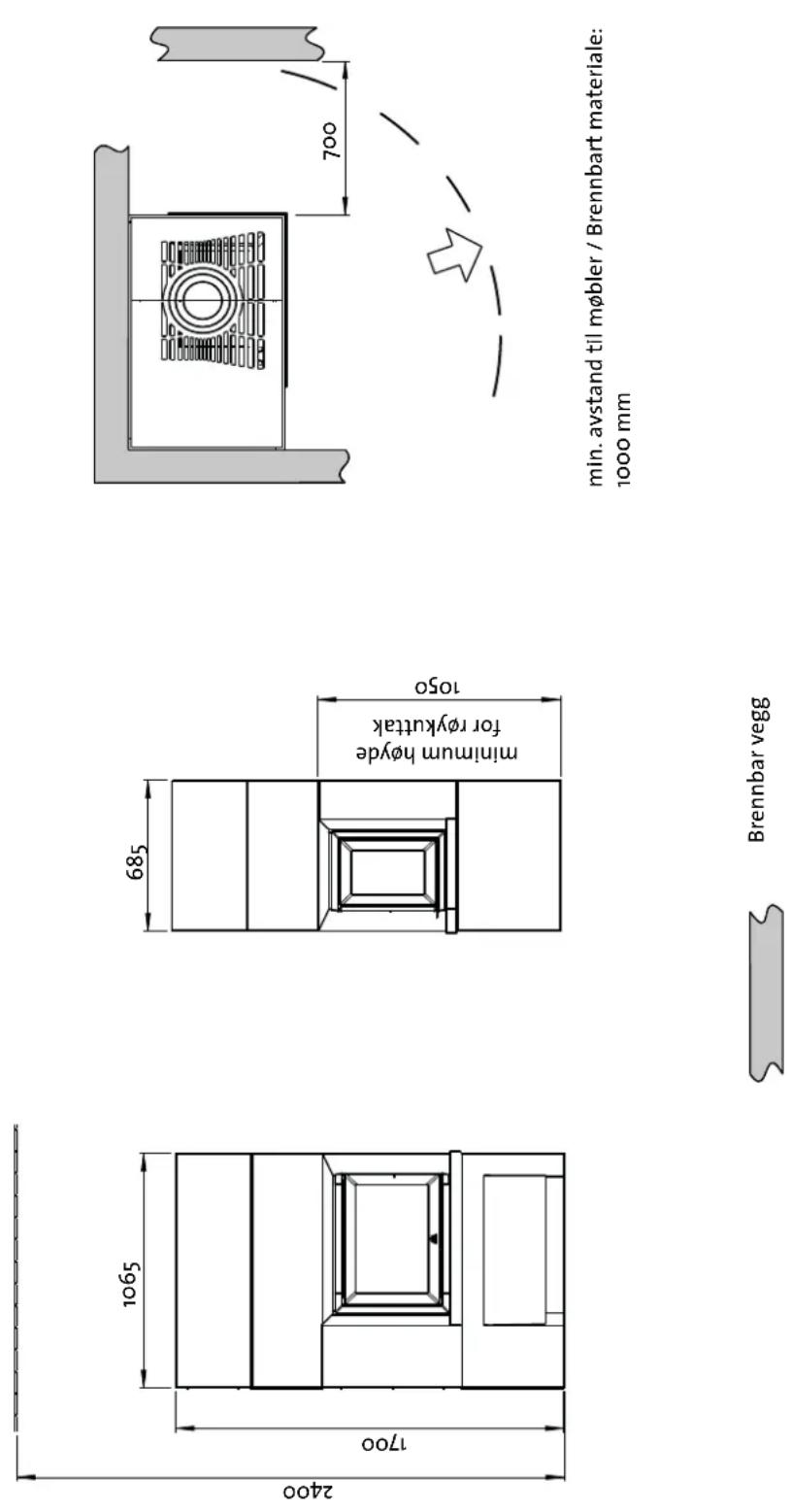
2.0 Technical Data
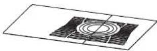
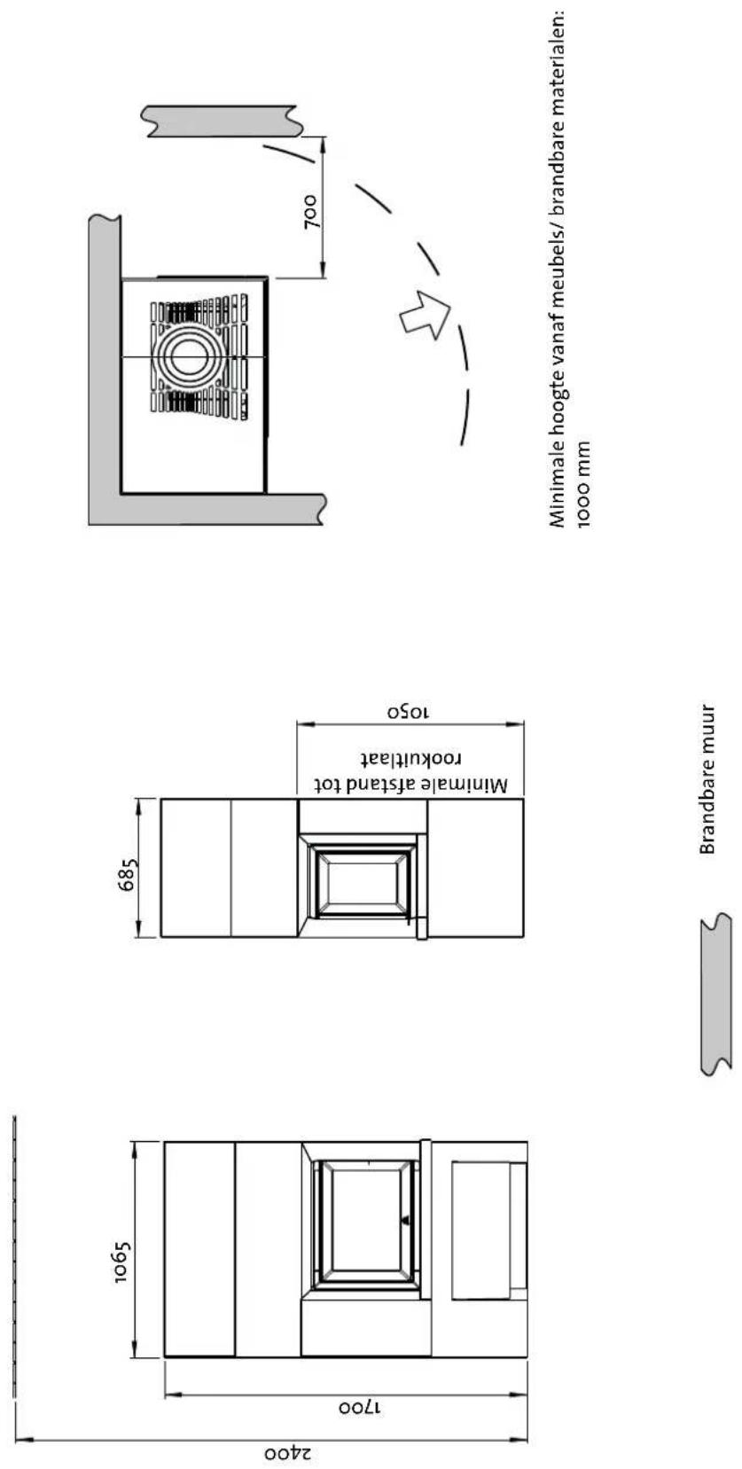
See dimensions, Fig. 2
Weight, surround, approx.: 292 kg
Weight, insert: 110 kg
| Height: | 1,700 | mm | |
| Width: | 1,065 mm | ||
| Depth: | 685mm | ||
| Minimum distance, hot-air vent to ceiling: | 700 mm. |
Optional extras: Floor plates
Outside air connection
| Bottom | plate | |
| Heat-storage | stone | system |
Technical data for I520 are available in the insert's manual
3.0 Safety
NB: To guarantee optimal performance and safety, Jøtul recommends that its stoves are fitted by a qualified installer (see www.jotul.com for a complete list of dealers).
Any modifications to the product by the distributor, installer or consumer may result in the product and safety features not functioning as intended. The same applies to the installation of accessories or optional extras not supplied by Jøtul. This may also be the case if parts that are essential to the functioning and safety of the fi replace have been disassembled or removed.
In all these cases, the manufacturer is not responsible or liable for the product and the right to make a complaint becomes null and void.
ENGLISH
3.1 Fire Prevention Measures
There is a certain element of danger every time you use your fi replace. The following instructions must therefore be followed:
- The minimum safety distances when installing and using the fireplace are given in fig. 2 in the installation manuals for the products.
- Ensure that furniture and other combustible materials are not too close to the fi replace. Combustible materials must not be placed within 1,000 mm of the fi replace opening.
- Allow the fire to burn out. Never extinguish the flames with water.
- The fi replace becomes hot when lit and may cause burns if touched.
- Only remove ash when the fi replace is cold. Ash can contain hot embers and should therefore be placed in a non-fi ammable container.
- Ash should be placed outdoors or be emptied in a place where it will not present a potential fire hazard
In the event of fire in the chimney.
- Close all doors and valves.
- Keep the fi rebox door closed.
- Check the loft and the basement for smoke.
- Call the fire brigade.
- Before a fireplace can be used after a fire or an attempted fire, the fireplace and the chimney must be inspected and found to be in order by competent personnel.
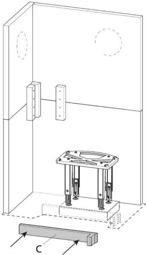
3.2 Floor
Foundation
You must make sure that the foundation is suitable for the fireplace. See "2.0 Technical Data" for specified weight.
We recommend the removal of any flooring that is not attached to the foundation (“floating floors”) beneath the installation.
Requirements for protection of wooden fl ooring beneath the fi replace
If you intend to place the product directly on a wooden floor, you must use a bottom plate (item no. 10047361, optional extra.
Requirements for protection of combustible fil oors in front of the fi replace
The front plate must comply with national laws and regulations. Contact your local building authorities regarding restrictions and installation requirements.
For Norway: Minimum 300 mm in front of the door and width at least the same as the door.
3.3 Walls
Distance to walls made of combustible material - see fig. 2.
The fireplace may be used with a semi-insulated flue pipe provided the distances between the fl replace and walls made of combustible materials are as shown in Fig. 2.
NB: Ensure that furniture and other combustible materials are not too close to the fireplace. Combustible materials must not be placed within 1,000 mm of the fi replace opening.
3.4 Ceiling
If the ceiling above the replace is made of combustible material, the minimum distance between the fireplace and ceiling must be 700 mm, i.e. a minimum ceiling height of 2,400 mm.
4.0 Installation
NB: Before installing the fireplace, check it carefully for any signs of damage.
NB: The product is heavy! Ask someone to help you when positioning and installing it.
NB: Read the installation and operating instructions for Jøtul I 520 (cat. no. 10044945 and Jøtul S 71/S 72 (cat. no. 10047331) carefully before installing the fi replace! Use the provided acrylic sealant for all joints.
Then fit the steel chimney in accordance with the operating instructions.
- The insert must be connected to a chimney and flue pipe approved for solid fuel fireplaces with a flue gas temperature of 305^ C.
- The cross-section of the chimney must be at least that of the flue pipe. ∅ 150 mm cross section.
- Several solid fuel products can be connected to the same chimney system if the chimney cross-section is adequate. See "2.0 Technical data".
For recommended chimney draught, see "2.0 Technical Data". If the draught is too strong, a smoke damper can be installed and used to reduce the draught.
4.1 Prior to installation
The basic product comes in a package with concrete elements. An insert (Jøtul 1520) and a leg rack are also included.
NB: Check the product for signs of damage when you unpack it.
NB: Check that the right insert is used for the selected surround.
Preparations
Before installation, it is necessary to decide:
• Where the smoke outlet is to be located.
• Possible use and location of external air supply.
Refer to manuals for installation of the parts.
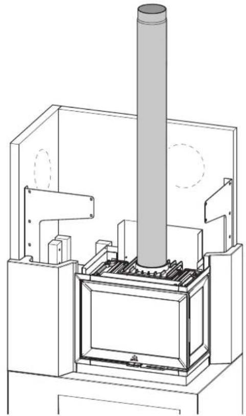
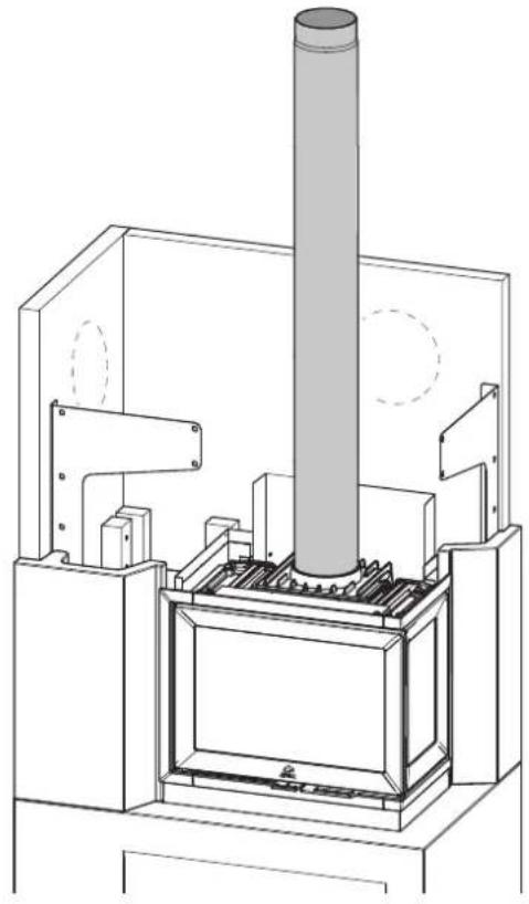
Smoke outlet
- S71/S72 is designed for installation with top or wall outlet.
- Follow the instructions from the Installation and Operating Instructions for Jøtul I 520 FR (cat. no. 30044745 for S71) or Jøtul I 520 FL (cat. no. 30044744 for S72).
Pipe with balanced chimney
IMPORTANT:
Use a flex hose from the start module and into the insert when you install a pipe with balanced flue. It is important to place the fl ex hose on the side of the burn chamber.
Do not install it behind the burn chamber so that it shuts down air flow.
ENGLISH
Fig.1a
S 71
G 1 stk (Art.nr 50047222)
S 71 FR
natural_image
Simple line drawing of a rectangular frame with mounting holes (no text or symbols)D 1 stk (Art.nr 50047219)
(S 71 FR)
natural_image
Technical line drawing of a mechanical bracket or housing (no text or symbols)natural_image
Simple line drawing of a rectangular frame with two side notches (no text or symbols)L 1 stk (Art.nr 10047235)
M 1 stk (Art.nr 10047236)
S 2 stk (Art.nr 10047330)
natural_image
Simple 3D rectangular block with no text or symbolsT 2 stk (Art.nr 10047329)
natural_image
Simple 3D rectangular block diagram with no text, numbers, or symbolsU 5 stk (Art.nr 10047332)

W 2 stk (Art.nr 10047328)
natural_image
Pure geometric line drawing of a vertical U-shaped structure with evenly spaced dots (no text or symbols)Fig.1a
S 71
G 1 stk (Art.nr 50047222)
S 71 FR

natural_image
Pure technical line drawing of a rectangular bracket (no text or symbols)D 1 stk (Art.nr 50047219)
(S 71 FR)

natural_image
Technical line drawing of a mechanical bracket or housing (no text or symbols)natural_image
Simple line drawing of a rectangular frame with corner holes (no text or symbols)L 1 stk (Art.nr 10047235)
M 1 stk (Art.nr 10047236)
S 2 stk (Art.nr 10047330)
natural_image
Simple 3D rectangular block diagram with no text or symbolsT 2 stk (Art.nr 10047329)
natural_image
Simple 3D rectangular shape with no text, numbers, or symbolsU 5 stk (Art.nr 10047332)

W 2 stk (Art.nr 10047328)
natural_image
Pure geometric line drawing of a V-shaped structure with mounting holes (no text or symbols)natural_image
Technical line drawing of a mechanical support structure with four vertical legs and mounting holes (no text or symbols)P 1 stk (Art.nr 30044745)
(I 520 FR for S71)

natural_image
Technical line drawing of a rectangular appliance with internal compartments and mounting feet (no text or symbols)Q 1 stk (Art.nr 30044744
(I 520 FL for S72)
natural_image
Technical line drawing of a rectangular industrial or laboratory device with internal compartments and a central circular component (no text or symbols)Sementsparkel
Akrylmasse

natural_image
Line drawing of a syringe with handle and spout (no text or symbols)Fig.2
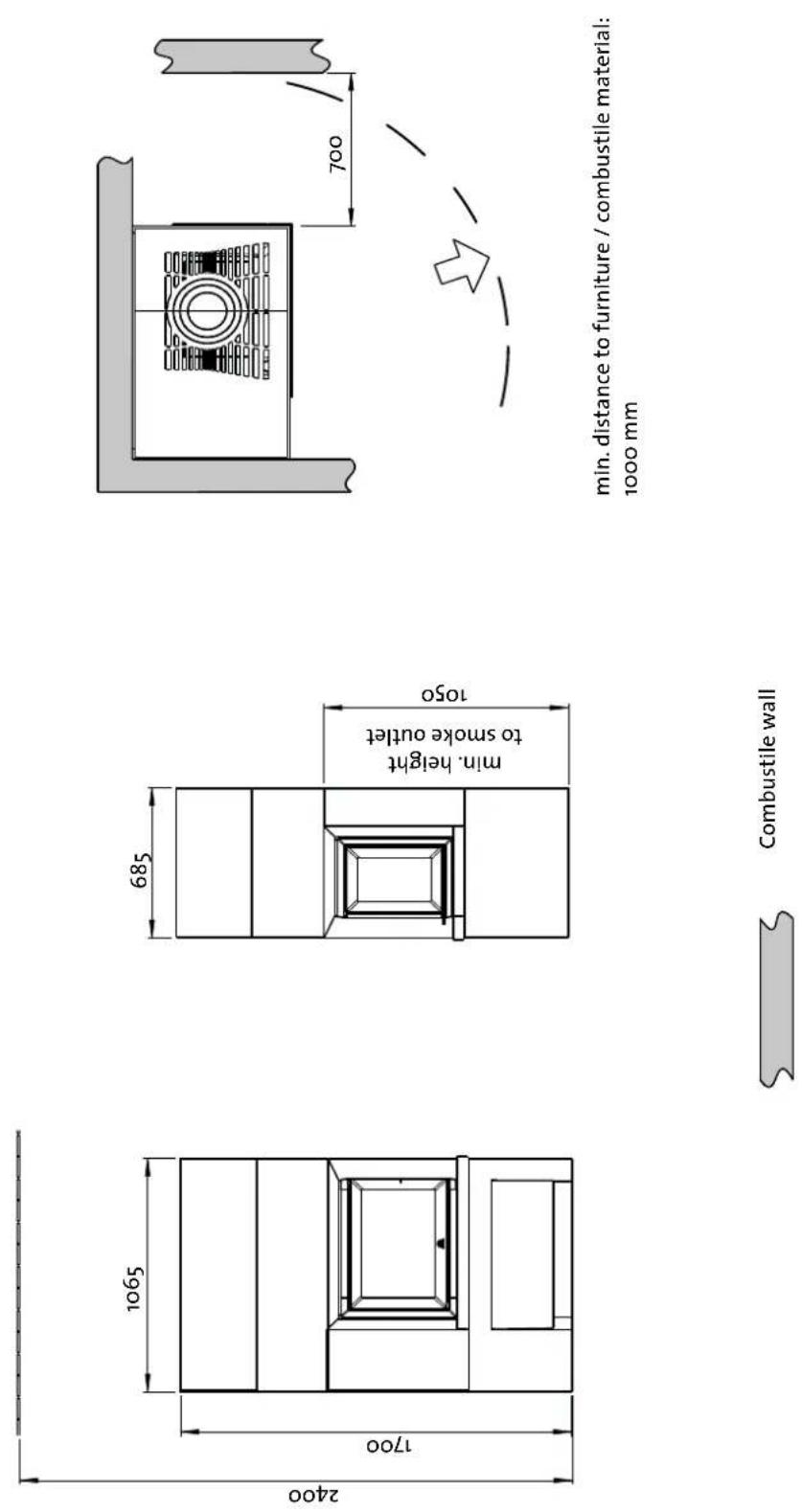
min. distance to furniture / combustile material: 1000 mm
900174
Combustile wall
ENGLISH
Fig.3

text_image
3,0mm 3,0mm X- Use a bottom plate (item no. 10047361, optional extra) if you intend to install the product on a combustible floor.
Fig.4
text_image
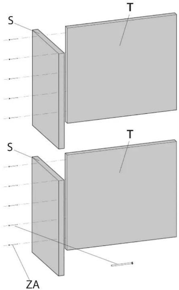
S T S ZA TNB: Reverse the Plates (T) if it is Jøtul S72 (for Jøtul I520FL) that will be installed.
Fig.5
text_image
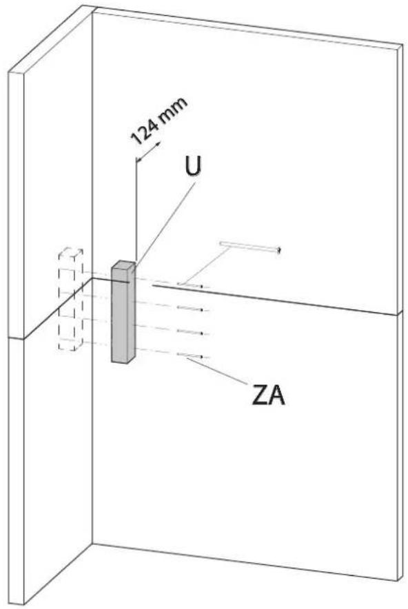
124 mm U ZAFig 6
text_image
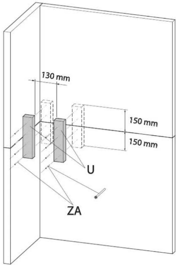
130 mm 150 mm 150 mm U ZAFig.7
natural_image
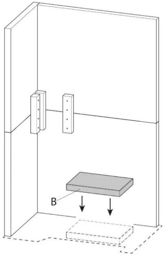
Diagram of a 3D box setup with two vertical supports and a rectangular block, showing directional arrows (no text or symbols)Fig.9
text_image
386mm 490 mm 480mm OFig.8
text_image
B 415 mm 175 mmFig.10

natural_image
Technical line drawing of a mechanical testing setup with a central platform and two circular components, enclosed in a rectangular enclosure (no text or symbols)ENGLISH
Fig.11
text_image
D/(J)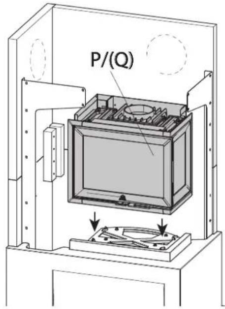
text_image
P/(Q)Fig.14
Fig.12
text_image
W ZC ZB ZB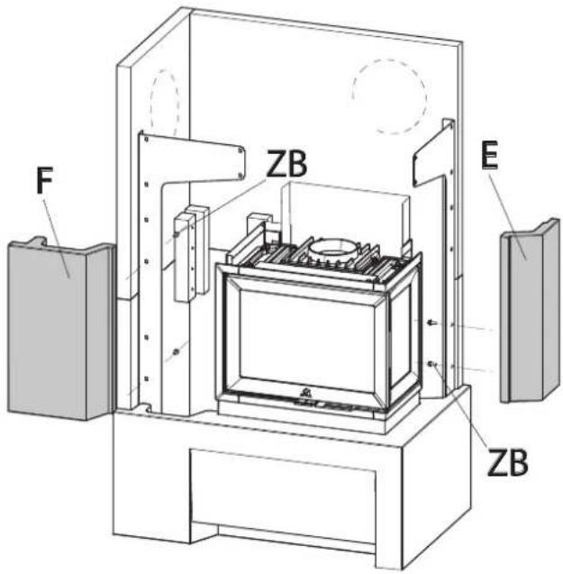
text_image
F ZB E ZBFig.14-b
text_image
53mm 53mmFig.13
Fig.15

natural_image
Technical line drawing of a mechanical device with a cylindrical component and internal components (no text or symbols)Fig.16-b

natural_image
Technical diagram of a mechanical assembly with warning symbol and arrows indicating components (no readable text or labels)Fig.16
text_image
G/(I) ZBFig.17
text_image
H ZBENGLISH
Fig.18
text_image
Y L MThe insert can be adjusted vertically with levelling screws. See Fig. 26 in the Installation and Operating Instructions for Jøtul I 520.
5.0 Installation Completed
Refer to the "Installation manual with technical data" for Jøtul I 520 (cat. no. 10044945) for the use and maintenance of the product!
NB: On delivery, the surround may have certain small visible scratches running across the prime coat. These are only cosmetic and do not impair the characteristics of the product. The scratches will be closed once the surround is painted after installation.
5.1 Painting
The product can be painted on the day after installation. Use water-based paint. If you want to create some surface texture, mix some tile cement into the paint.
5.2 Minor Damage
Once the insert has been installed, any nicks or irregularities in the concrete should be filled using the cement filler included in the kit.
- To achieve the best result, the surround should be rubbed down with fi ne sandpaper, smoothing any unevenness or sharp edges prior to painting.
- Then apply one coat.
- Mix the powder (cement filler) with water to form a smooth paste (like toothpaste).
- Smooth away any unevenness, allow to dry and then rub down with fine sandpaper.
- If the hole is deep, we recommend applying the filler in two stages to prevent it from sinking.
- Apply a second coat of the desired colour.
6.0 Optional extras
Steel floor plate in front of the product
Cat. no. 51047337 (NO/SE)
Cat. no. 51046304 (DE)
Glass floor plate in front of the product
Cat. no. 50047338 (NO/SE)
Cat. no. 50047517 (DE)
Outside air connection
Cat. no. 51047509
Bottom plate
Cat. no. 10047361
Heat-storage stone system
Cat. no. 10026701
7.0 Recycling
7.1 Recycling Packaging
Your fi replace is delivered with the following packaging:
- A wooden pallet that can be cut up and burned in the fi replace.
- Cardboard packaging that should be taken to a local recycling facility.
- Plastic bags that should be taken to a local recycling facility.
7.2 Recycling the Fireplace
The fi replace is made of:
• Metal that should be taken to a local recycling facility.
- Glass that should be disposed of as hazardous waste. The glass in the fireplace may not be placed in a regular source segregation container.
- Vermiculite burn plates that can be disposed of in regular waste containers
8.0 Warranty
Jøtul AS provides its customers with a ten-year warranty with the right to return external cast-iron items if they show defects as a result of faulty materials and/or manufacturing after the initial purchase/installation of the fireplace. The buyer is entitled to return the goods provided that the fireplace has been installed in compliance with current laws and regulations and in compliance with Jøtul's installation and operating instructions.
The warranty does not cover:
The installation of optional extras, for example, to rectify local draught conditions, air supply or other circumstances beyond Jøtul's control. The warranty does not cover consumables, such as burn plates, smoke baffles, fire grates, bottom grates, brick refractories, dampers and gaskets as they deteriorate over time due to normal wear and tear. The warranty does not cover damage caused as a result of using unsuitable fuel when lighting the fire, such as driftwood, impregnated and painted wood, plank offcuts, chipboard, etc. Overheating may easily occur if unsuitable fuel is used, i.e. the fireplace becomes red hot, which causes the paint to discolour and castings to crack.
The warranty does not apply to damage caused while the product is in transit from the distributor to the delivery address. Nor does it cover damage caused by the use of non-original parts..
Checked
Jøtul pursue a policy of constant product development. Products supplied may therefore differ in specification, colour and type of accessories from those illustrated and described in the brochure.
Jøtul AS has a quality system that conforms to NS-EN ISO 9001 for product development, manufacturing, and distribution of stoves and fireplaces. This policy gives our customers quality and safety piece of mind as a result of Jøtul's vast experience dating back to when the company first started in 1853.