Meccanoid G15KS - Toys Spin Master - Free user manual and instructions
Find the device manual for free Meccanoid G15KS Spin Master in PDF.

| Product Type | Programmable Construction Robot |
| Brand | Spin Master |
| Model | Meccanoid G15KS |
| Recommended Age | 10 years and up (adult supervision required) |
| Number of Pieces | 1188 |
| Power Supply | Rechargeable Ni-MH battery 1800 mAh (included) |
| Charger | AC/DC wall charger 10.4 W included |
| Microprocessor | MeccaBrain™ |
| Motors and Actuators | 8 servo motors, 2 motors with gears |
| Additional Modules | LED module, 2 tools, rear wheel assemblies |
| Connectivity | Bluetooth, mini-USB port |
| Main Features | Voice commands, intelligent movement learning (L.I.M.™), programming via mobile app (iOS/Android) |
| Available Languages | Programmable in multiple languages (download at www.meccano.com) |
| Safety | Electric toy - do not use under water, cord strangulation hazard, adult supervision mandatory |
| Care and Cleaning | Clean with a soft cloth, avoid moisture, keep sensors clean |
| Box Contents | 1188 pieces, 1 charger, 1 Ni-MH battery, 1 MeccaBrain, 1 LED module, 2 tools, 8 servo motors, 2 rear wheels, 2 motors with gears, 1 USB cable |
Frequently Asked Questions - Meccanoid G15KS Spin Master
User questions about Meccanoid G15KS Spin Master
0 question about this device. Answer the ones you know or ask your own.
Ask a new question about this device
Download the instructions for your Toys in PDF format for free! Find your manual Meccanoid G15KS - Spin Master and take your electronic device back in hand. On this page are published all the documents necessary for the use of your device. Meccanoid G15KS by Spin Master.
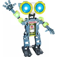
USER MANUAL Meccanoid G15KS Spin Master
text_image
10+ Years/Ans/Años Jahre/Jaar/Anni Anos/Лет MECCANO M 1x NI-MH 1800... BC• INSTRUCTION GUIDE
• MODE D'EMPLOI
• GUÍA DE INSTRUCCIONES
• BEDIENUNGSANLEITUNG
• GEBRUIKSAANWIJZING
• GUIDA PER L'USO
• GUIA DE INSTRUÇÕES
• ИНСТРУКЦИЯ ПО
ИСПОЛЬЗОВАНИЮ
For instructions in other languages, visit www.meccano.com
⚠ WARNING: Adapter cord could be a strangulation hazard. Not for use by children under 3 years of age.
FCC Statement: This device complies with Part 15 of the FCC rules. Operation is subject to the following two conditions: (1) This device may not cause harmful interference, and (2) This device must accept any interference received, including interference that may cause undesired operation. This equipment has been tested and found to comply with the limits for Class B digital devices pursuant to Part 15 of the FCC rules. These limits are designed to provide reasonable protection against harmful interference to radio communications. This equipment generates, uses and can radiate radio frequency energy and, if not installed and used in accordance with the instruction, may cause harmful interference to radio communication. However, there is no guarantee that interference will not occur in a particular installation. If this toy does cause interference to radio or television reception (you can check this by turning the toy off and on while listening for the interference), one or more of the following measures may be useful: • Reorient or relocate the receiving antenna • Increase the separation between the toy and the radio or the TV • Consult the dealer or an experienced TV-radio technician for help. Shielded cables must be used with this unit to ensure compliance with the Class B FCC limits. Shielded cables must be used with this unit to ensure compliance with the Class B FCC limits. NOTE: Changes, adjustments or modifications to this unit, including but not limited to, replacement of any transmitter component (crystal, semiconductor, etc.), could result in a violation of FCC rules under part 15 and/or 95 and must be expressly approved by Spin Master Ltd., or they could void the user's authority to operate the equipment. Connect the equipment into an outlet on a circuit different from that to which the receiver is connected
GB Content: 1188 Parts, 1 AC/DC wall mount charger (10.4W), 1 Rechargeable Ni-MH battery 1800 mAh, 1 MeccaBrain™, 1 LED module, 2 hand tools, 8 servos, 2 rear wheel assembly, 2 motor gear box assembly, 1 USB cable
CANADIAN Class B statement: This device complies with Industry Canada Licence-exempt RSS-210. Operation is subject to the following two conditions: (1) this device may not cause interference, and (2) this device must accept any interference, including interference that may cause undesired operation of the device.
GB Before first-time use, charge the 6.0V NiMH rechargeable battery pack for 2 hours. Rechargeable battery should only be charged under adult supervision. Do not recharge a battery pack that shows leakage or corrosion. Immediately remove the battery charger from power supply after charging is finished (Charger light turned green). The product may have unexpected movement. User and third body should stay at least 50 cm away from the product to avoid unexpected impact.
CAUTION Cut Hazard: Product has functional sharp points. Contact may result in injury. Always keep points away from fingers and body. Handle with care. Use with adult supervision. All the wires should be well attached in the provided wire clip #M044 to avoid hazards caused by loose wire. Extra wire clips are provided in the package. Do not put the phone into the phone tray except in motion capture mode. Activate the product only when the area is appropriate for the intended use (free area, no obstacles). The product is intended to be played on floor.
3.4 PROGRAM WITH APP 58
CONSUMER INFORMATION 89-93
- ASSEMBLAGE....5-52
1.1 MONTAGE DU ROBOT 7-52
- BRANCHEMENTS ET CONNEXIONS....53
2.1 BRANCHEMENTS ET TÉLÉCHARGEMENT DE LA LANGUE. 53
2.2 RÉALISATION DES BRANCHEMENTS....59
- JEU....60
3.1 JOUONS! 60
3.2 LISTE DES COMMANDES....61
3.3 COMMANDES VOCALES 62
3.4 PROGRAMMATION VIA L'APPLICATION....63
INFORMATIONS DESTINÉES AU CONSOMMATEUR....89-93
- MONTAJE • ZUSAMMENBAU • MONTAGE • MONTAGGIO • MONTAGEM • СБОРКА 5-52
1.1 CONSTRUYETU ROBOT • BAUE DEINEN ROBOTER ZUSAMMEN • BOUW JE EIGEN ROBOT • COSTRUISCI IL TUO ROBOT • MONTE SEU ROBÔ • СБОРКА РОБОТА.... 7-52
- CONÉCTALO • VERBINDEN UND ANSCHLIESSEN • AANSLUITEN • COLLEGAMENTI • CONECTE • ПОДКЛЮЧЕНИЕ И УСТАНОВКА....53
2.1 CONÉCTALO Y DESCARGA TU IDIOMA • ANSCHLIESSEN UND DEINE SPRACHE HERUNTERLADEN • SLUIT AAN EN DOWNLOAD JE TAAL • COLLEGA E SCARICA LA TUA LINGUA • CONECTE E BAIXE SEU IDIOMA ПОДКЛЮЧЕНИЕ И ЗАГРУЗКА ЯЗЫКА ....53
2.2 CONECTA LOS COMPONENTES ELECTRÓNICOS • ELEKTRONISCHE TEILE VERBINDEN • DE ELEKTRONICA AANSLUITEN • COLLEGA I COMPONENTI ELETTRONICI ПОДКЛЮЧЕНИЕ ЭЛЕКТРОННЫХ КОМПОНЕНТОВ ....64,69,74,79,84
- CÓMO JUGAR • SPIELEN • SPELEN • GIOCO • ВОСПРОИЗВЕДЕНИЕ ....65,70,75,80,85
3.1 VAMOS A JUGAR • SO WIRD GESPIELT • LATEN WE SPELEN • COMINCIAMO • ДАВАЙ ПОИГРАЕМ....65,70,75,80,85
3.2 TARJETA DE COMANDOS • BEFEHLSKARTE • COMMANDO-KAART • SCHEDA DEI COMANDI • KAPTA KOMAHD....66,71,76,81,86
3.3 COMANDOS DE VOZ • SPRACHBEFEHLE • SPRAAKOPDRACHTEN • COMANDI VOCALI • ГОЛОСОВЫЕ КОМАНДЫ....67,72,77,82,87
3.4 PROGRAMAR CON APLICACIÓN • KOSTENLOSE APP HERUNTERLADEN • PROGRAMMEERBAAR VIA APP • PROGRAMMA CON L'APP • ПРОГРАММИРОВАНИЕ С ПОМОЩЬЮ ПРИЛОЖЕНИЯ....68,73,78,83,88 INFORMACIÓN PARA EL CONSUMIDOR • VERBRAUCHERHINWEISE INFORMATIE VOOR GEBRUIKERS • INFORMAZIONI PER I CONSUMATORI • INFORMAÇÕES PARA O CONSUMIDOR • ИНФОРМАЦИЯ ДЛЯ ПОТРЕБИТЕЛЕЙ....89-93
1
ASSEMBLY • ASSEMBLAGE • MONTAJE • ZUSAMMENBAU • MONTAGE • MONTAGGIO • MONTAGEM • СБОРКА

M103 x1

M902 x8

M903L x1

M903R x1

M016 x8

M006 x8

M905 x1
M013 x1

M101 x8

M100 x8

M009 x2

M215 x1
M023 x4
M020 x1
M904 x1
M008 x4
M008 x4
M017 x14
M019 x3
M119 x3
M022 x2
M038 x2
M026 x1

M031 x2
M212 x2
M107 x2
x1
x1
M216 x4

M027 x10

M027 x2
M004 x9

M002 x12

M046 x4

M217 x10

M003 x30

M001 x44

M213 x2

M007 x2

M021 x2

M029 x8

M010 x10
USB x1
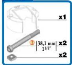
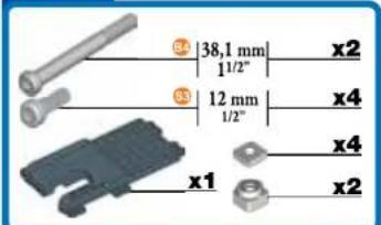
38,1 mm 1 ^1/2 "
B696 x20
31,75 mm 1 ^1/4 "
C935×2

A347 (0147G) x8

A911 (0111) x2

47 (0147D) x36

A411 [0111A] x386

A511 (0111C) x 1 1

M909 x2

M908 x6

M906 x4

A337(0037A)×438

M907x26

M044 x12

M200 x4

M201 x4
C994 x1

C993 x1
A136 (0036C) x 1

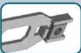
CONSTRUCTION TIPS
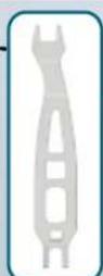
natural_image
Red screwdriver with metal handle and mounting bracket (no text or symbols)
▶
▶

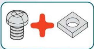
natural_image
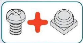
Three mechanical parts: a bolt, a red plus sign, and a gray square (no text or symbols)▼
1
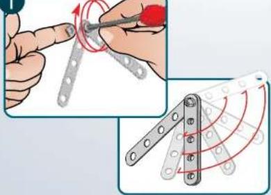
text_image
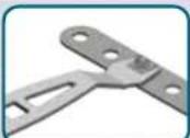
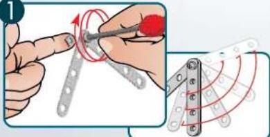
Technical illustration showing hand tool application on a metal bracket with red motion arrows and a close-up of the component.2
natural_image
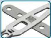
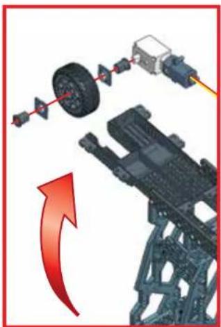
Illustration showing two mechanical hand tools: one with a curved tool and red rotation arrow, the other with a cross-shaped mechanism (no text or symbols)
natural_image
Illustration of two types of screws: a spherical screw and a square button, with a red plus sign in the center (no text or symbols)▼
1
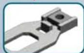
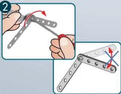
text_image
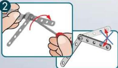
Technical illustration showing a hand using a tool to adjust a mechanical component with red motion arrows and circular motion patterns.2
natural_image
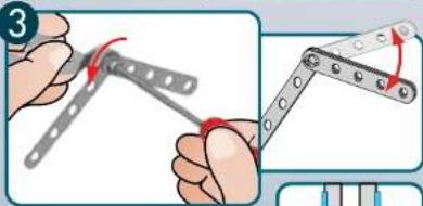
Illustration of two hands using a tool to adjust metal parts, showing motion and angle (no text or symbols)3
text_image
Illustration showing two mechanical tools for turning a bracket, with Chinese text labels and red arrows indicating motion.
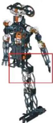
1.1 BUILD YOUR ROBOT • MONTAGE DU ROBOT • CONSTRUYE TU ROBOT • BAUE DEINEN ROBOTER ZUSAMMEN • BOUW JE EIGEN ROBOT • COSTRUISCI IL TUO ROBOT • MONTE SEU ROBÔ • CBOPKA POBO
natural_image
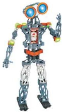
Illustration of a humanoid robot with blue eyes and orange accents (no text or symbols)
text_image
1 x1 31,75 mm x2 1/4" x1 x2 1:1 M ABCCANO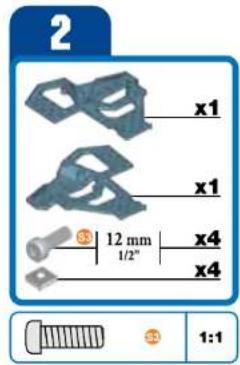
text_image
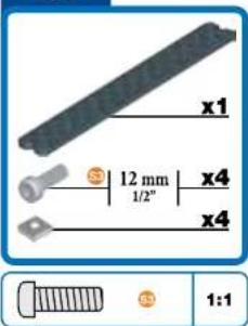
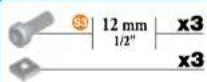
2 x1 x1 3 12 mm 1/2" x4 x4 1:1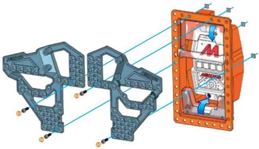
text_image
Technical diagram of a mechanical assembly with labeled components and directional arrows indicating motion or flow.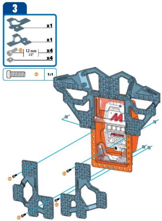
text_image
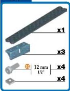
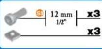
3 x1 x1 12 mm x4 x4 1:1 x3 x3 x3 x3 x3 AECOVAO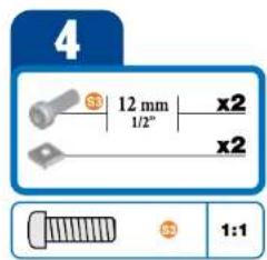
text_image
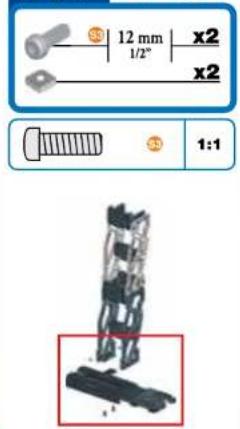
4 12 mm x2 1/2" x2 1:1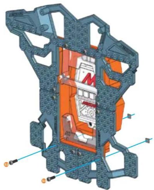
natural_image
3D cutaway diagram of a mechanical assembly with orange internal components and blue structural elements (no text or symbols)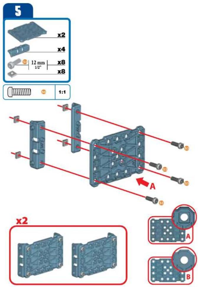
text_image
5 x2 x4 12 mm x8 x8 1:1 x2 A A B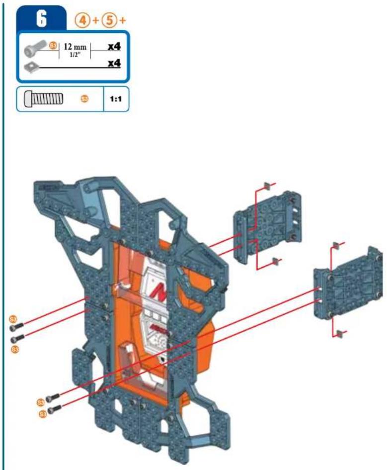
text_image
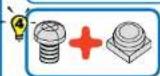
6 ④+⑤+ 12 mm x4 1/2" x4 1:1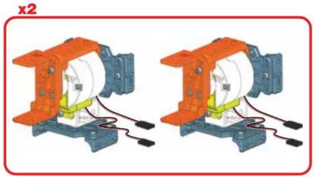
natural_image
Two identical mechanical components with orange and blue parts, connected by wires (no text or symbols visible)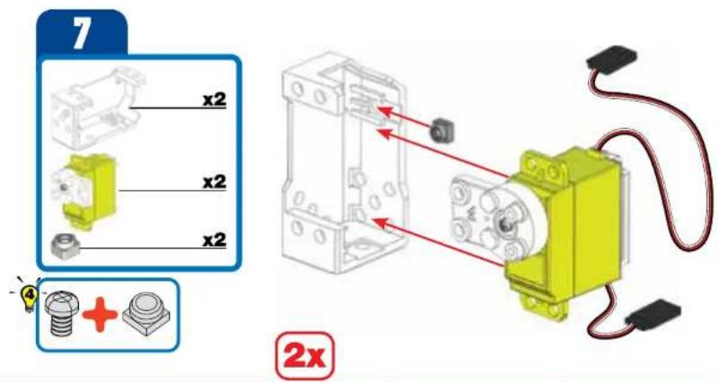
text_image
7 x2 x2 x2 + 2x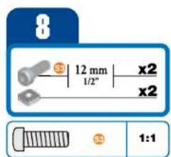
text_image
8 12 mm x2 1/2" x2 1:1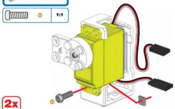
text_image
1:1 2x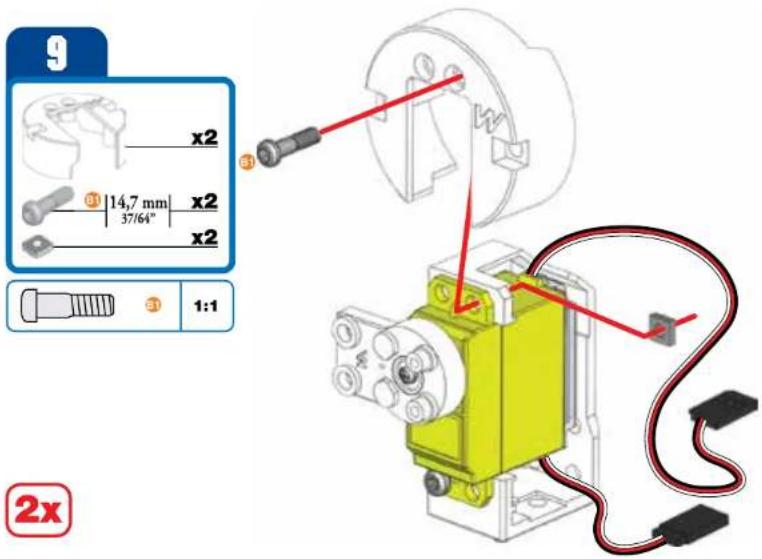
text_image
9 x2 14,7 mm x2 37/64" x2 1:1 ③ ④ 2x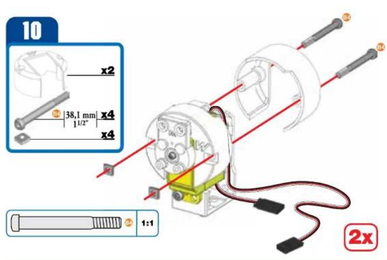
text_image
10 x2 38,1 mm x4 1/2" x4 1:1 2x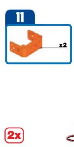
text_image
11 x2 2x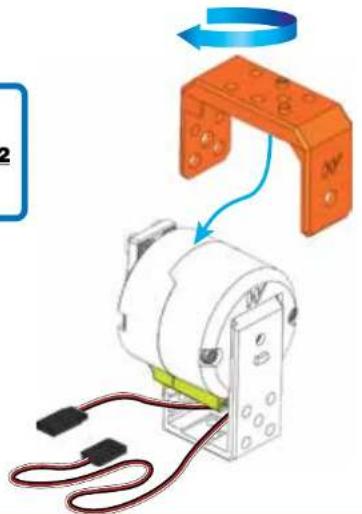
text_image
Diagram showing a mechanical assembly with labeled components and directional arrows indicating motion or rotation.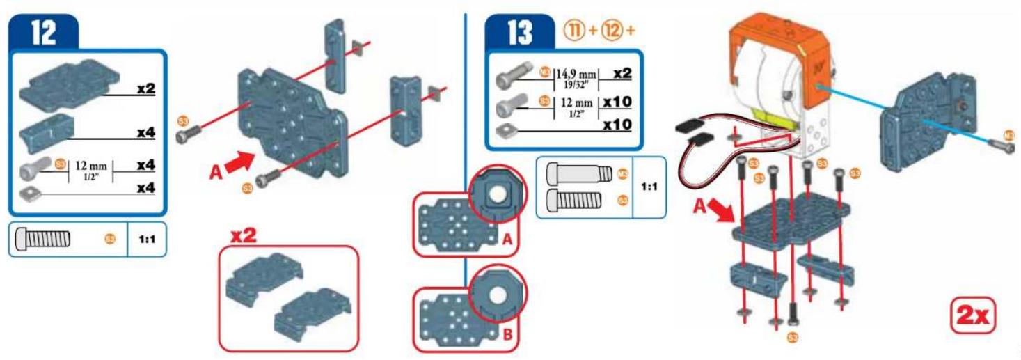
text_image
12 x2 x4 12 mm x4 1/2" x4 1:1 A x2 A B 13 ⑪ + ⑫ + 14,9 mm x2 19/32" 12 mm x10 1/2" x10 1:1 A A 2x14

text_image
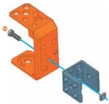
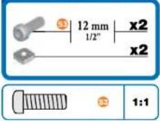
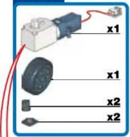
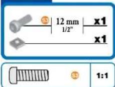
x2 12 mm x2 1/2" 7 mm x4 5/16" S3 1:1 N3
natural_image
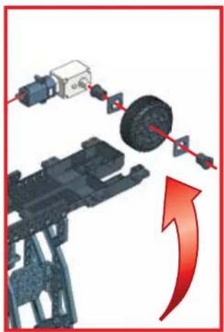
Mechanical assembly diagram showing a motor with orange housing and connected components (no text or symbols visible)x2
natural_image
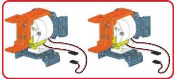
Two identical mechanical components with orange and blue parts, connected by wires (no text or symbols visible)15

text_image
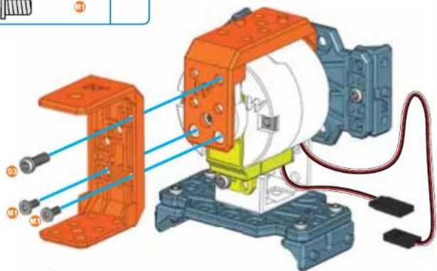
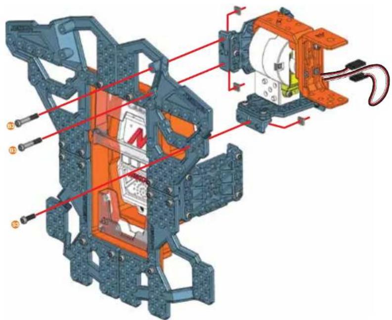
Technical diagram of a mechanical assembly with labeled components and red annotations indicating parts of each part.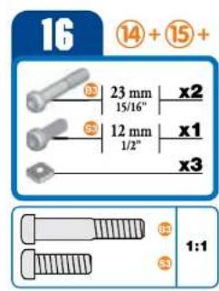
text_image
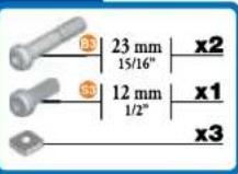
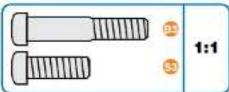
16 ⑭ + ⑮ + 23 mm x2 15/16" S3 12 mm x1 1/2" x3 S3 1:1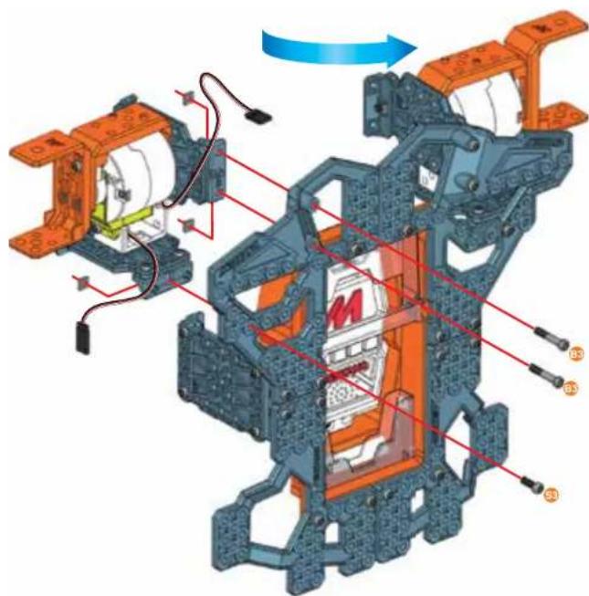
natural_image
Mechanical assembly diagram showing motor components and wiring (no text or labels)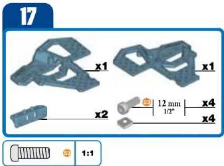
text_image
17 x1 x1 x2 12 mm 1/2" x4 x4 1:1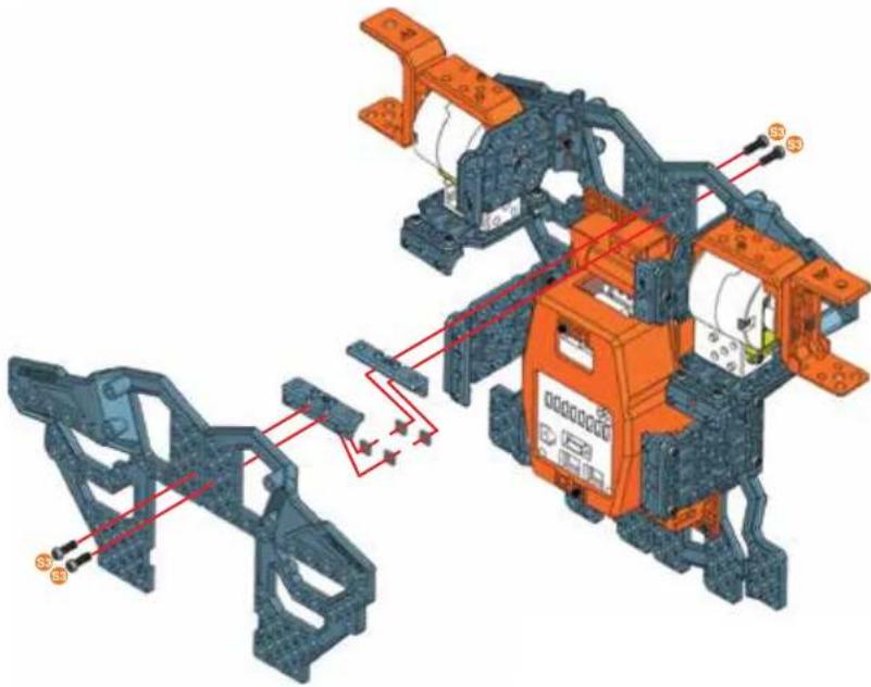
natural_image
3D mechanical assembly diagram showing orange components and red wiring connections (no text or symbols)18
text_image
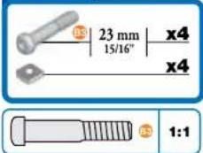
23 mm 15/16" x4 x4 1:1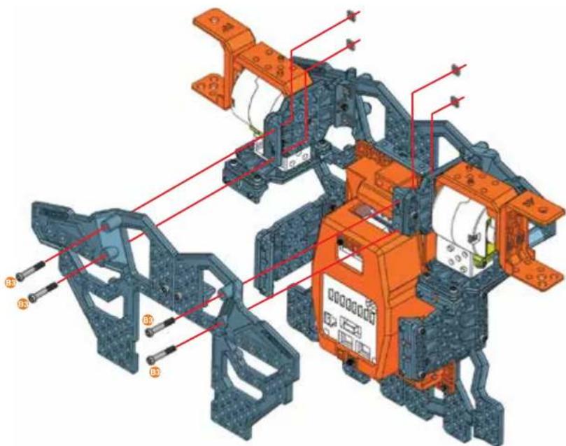
text_image
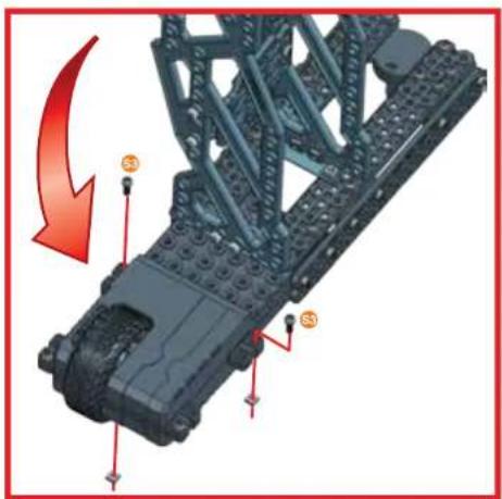
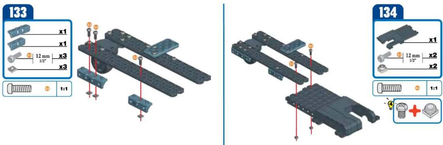
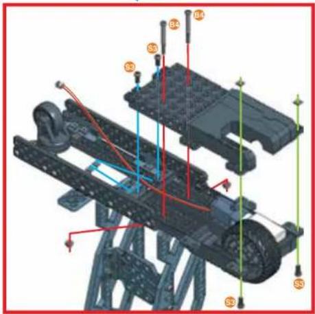
Technical diagram of a vehicle chassis with labeled components and red annotations indicating assembly or maintenance areas.19

natural_image
3D mechanical assembly diagram showing internal components with orange and blue parts, no visible text or symbols
text_image
20 x3 x6 12 mm x12 1/2" x12 1:1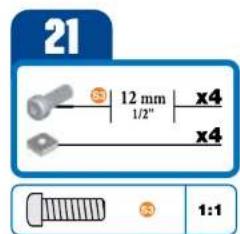
text_image
21 12 mm x4 1/2" x4 1:1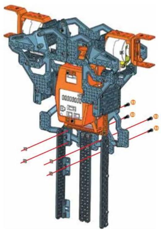
text_image
Technical diagram of a mechanical assembly with labeled components S3 and S4, showing structural connections and assembly details.22
text_image
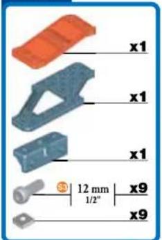
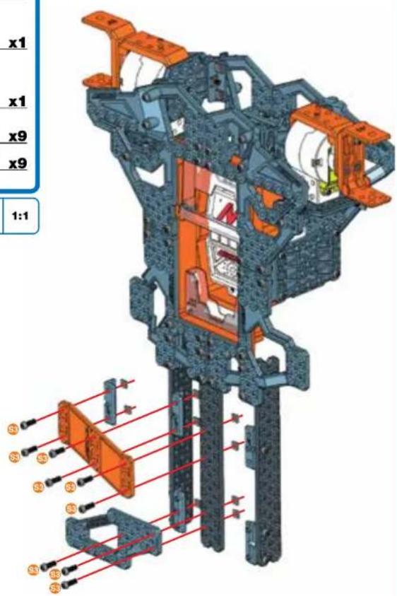
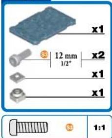
x1 x1 x1 12 mm 1/2" x9 x9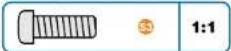
text_image
x1 x1 x9 x9 1:123
text_image
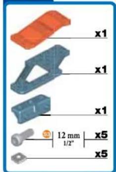
x1 x1 x1 x1 12 mm 1/2" x5 x5
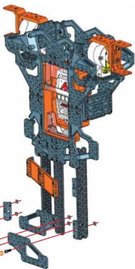
natural_image
3D cutaway diagram of a mechanical assembly with orange and blue components, no visible text or symbols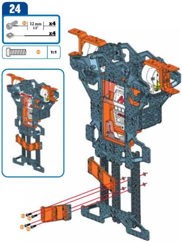
text_image
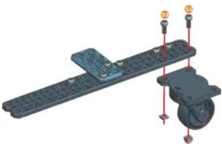
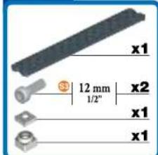
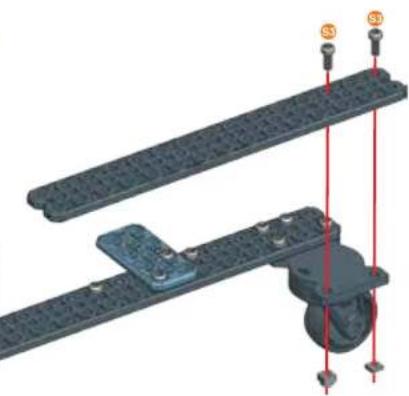
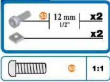
24 12 mm x4 1/2" x4 1:1 S3 S3 S3 S3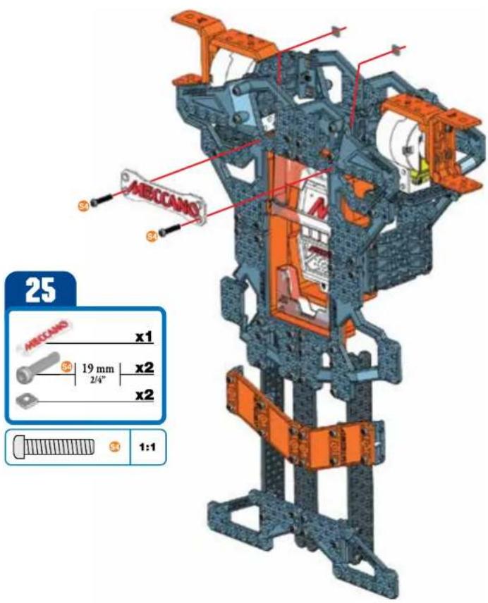
text_image
25 ABCCANO x1 19 mm x2 2/4" x2 1:126
text_image
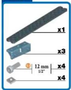
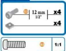
x1 x3 12 mm 1/2" x4 x4
27
text_image
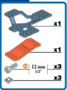
x1 x1 12 mm 1/2" x3 x3
28
text_image
x1 12 mm 1/2" x4 x4 1:1
29
text_image
x1 x3 12 mm 1/2" x4 x4
text_image
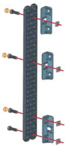
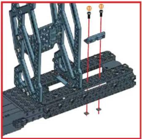
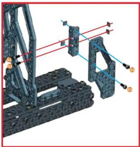
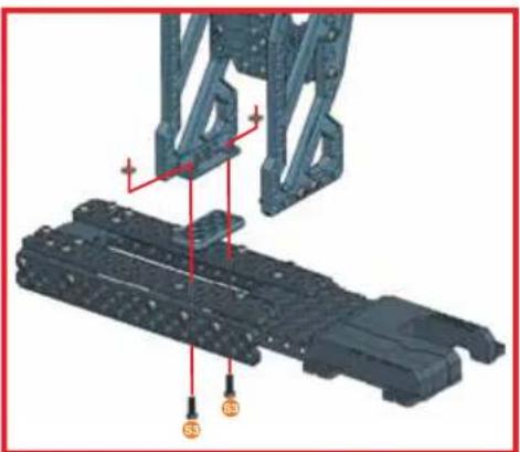
Diagram showing three vertical components with red arrows pointing to labeled pins, likely illustrating a mechanical or electrical assembly.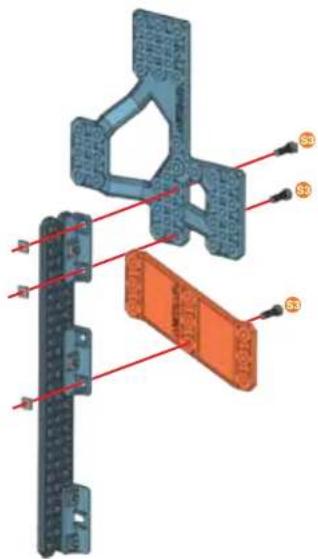
text_image
Technical diagram of a mechanical assembly with labeled components and red alignment lines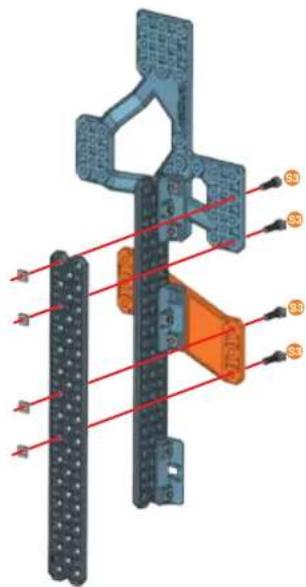
text_image
Technical diagram of a mechanical assembly with labeled components and red alignment lines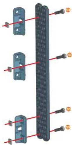
text_image
Technical diagram showing labeled components of a mechanical or electrical component with red lines and numbered annotations (S0, S3)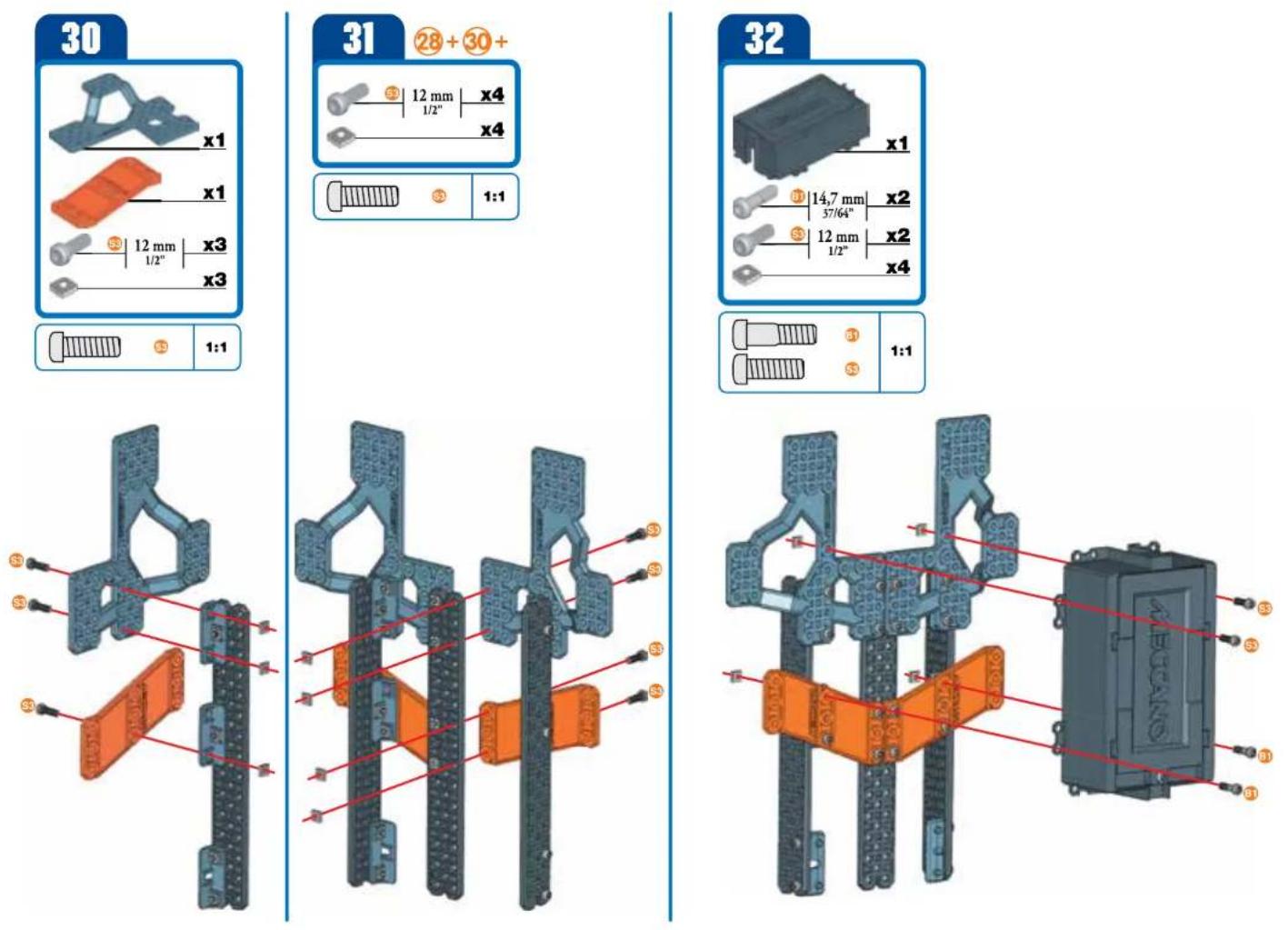
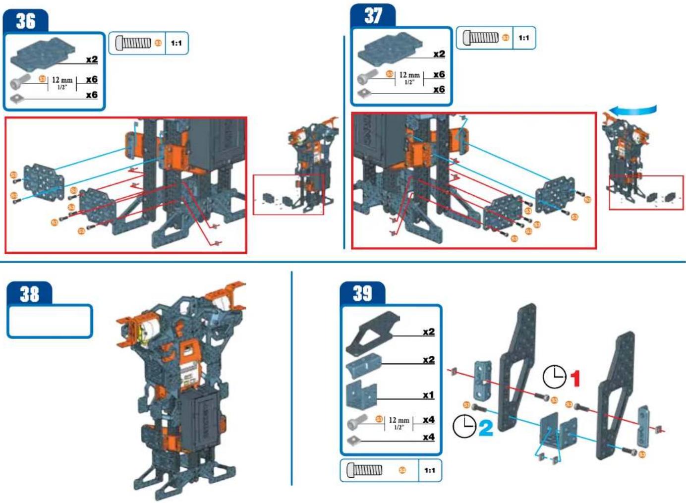
40
text_image
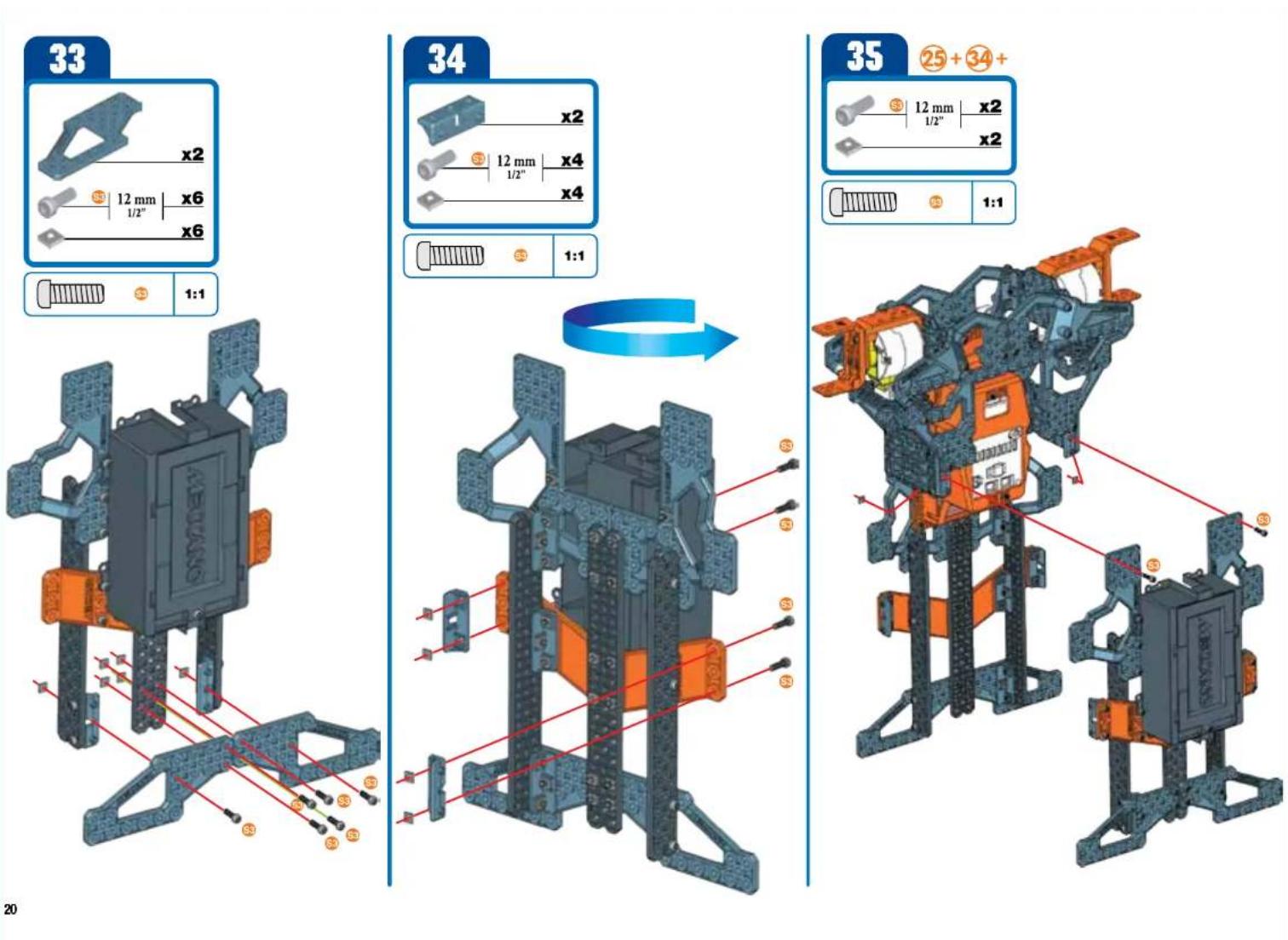
x2 12 mm x4 1/2" x4 1:1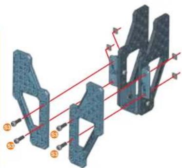
natural_image
3D mechanical component diagram with red alignment lines and orange mounting points (no text or symbols)41
text_image
x1 12 mm 1/2" x2 x1 x1 1:1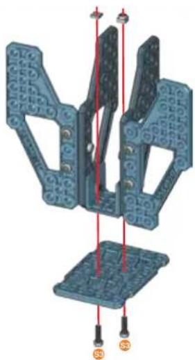
natural_image
3D mechanical assembly diagram showing two blue components with red alignment lines and mounting points (no text or symbols)42
text_image
12 mm 1/2" x4 x4 1:1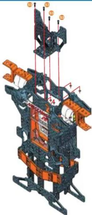
text_image
Technical diagram of a mechanical assembly with labeled components and structural elements43
text_image
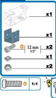
x1 x1 12 mm 1/2" x2 x1 x2 1:1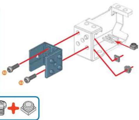
natural_image
Technical diagram of a mechanical assembly with red wiring and labeled components (no readable text or symbols)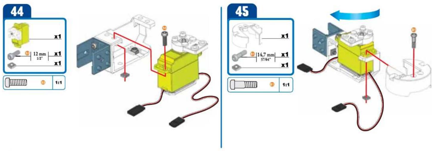
text_image
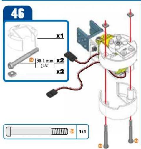
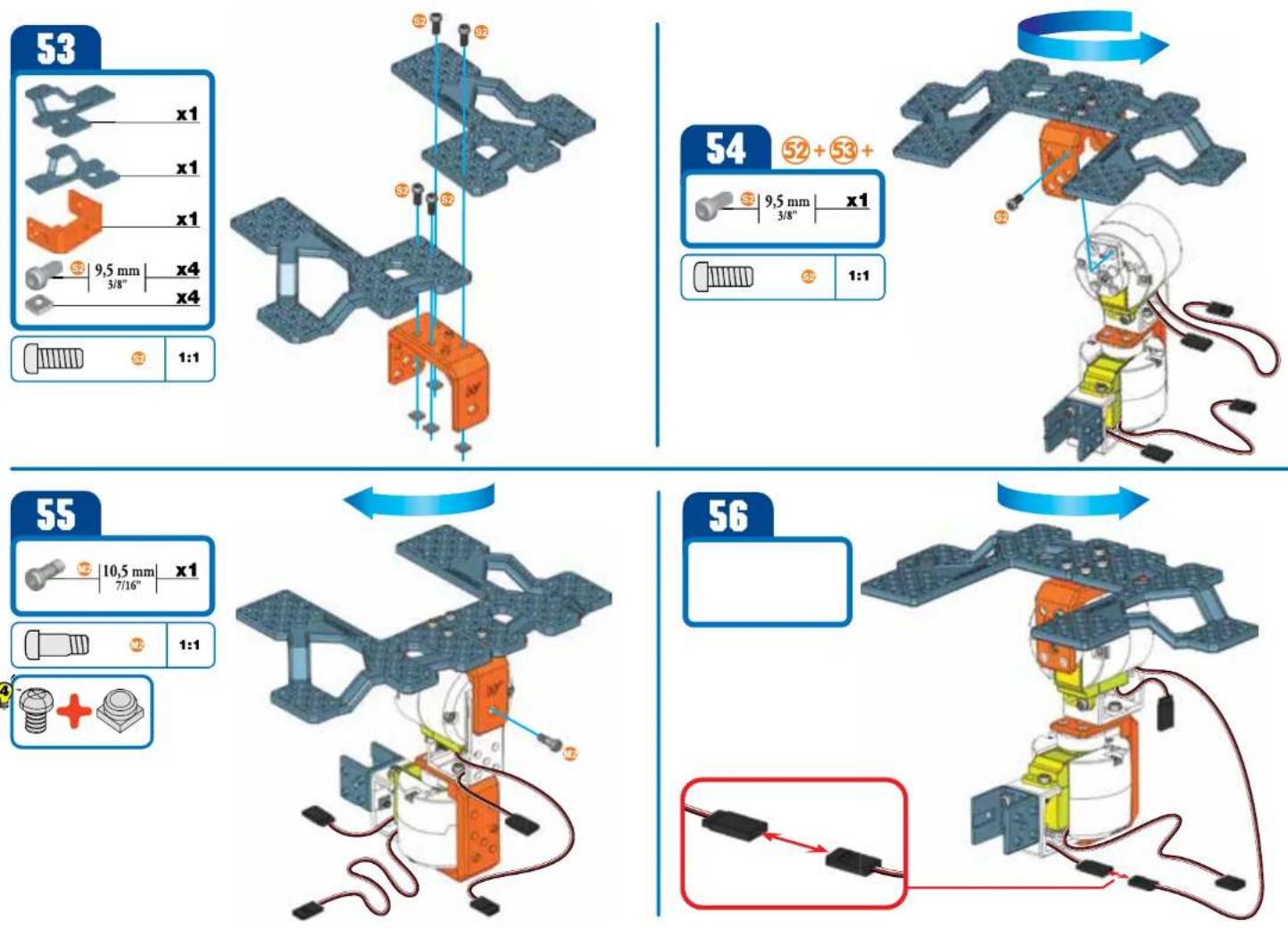
46 x1 38,1 mm x2 1/2" x2 1:1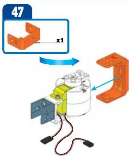
text_image
47 x1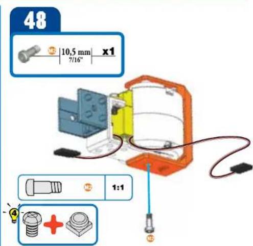
text_image
48 10,5 mm x1 7/16" 1:1
text_image
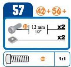
57 42 + 56 + 12 mm x2 1/2" x2 1:1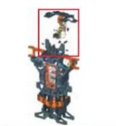
natural_image
3D rendered mechanical component with orange and blue parts, no visible text or symbols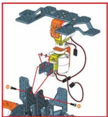
natural_image
Mechanical assembly diagram showing robotic arm and structural components (no text or labels)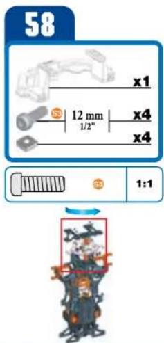
text_image
58 x1 12 mm x4 1/2" x4 1:1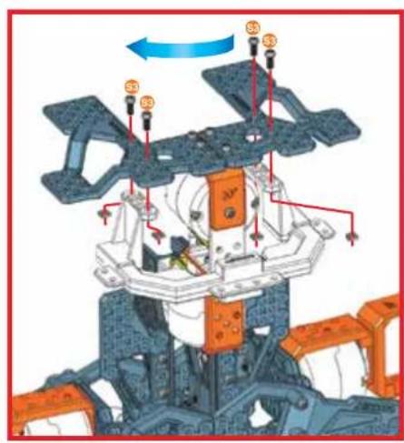
text_image
Technical diagram of a mechanical assembly with labeled components and directional arrows indicating motion or flow.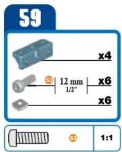
text_image
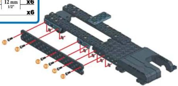
59 x4 12 mm x6 1/2" x6 1:1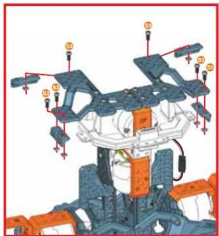
natural_image
Mechanical assembly diagram showing a multi-stage frame with labeled components (no readable text or symbols)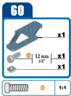
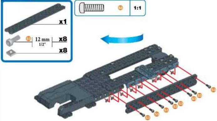
text_image
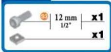
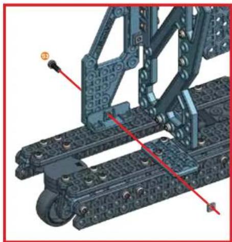
60 x1 12 mm x1 1/2" x1 x1 1:1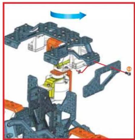
natural_image
Mechanical assembly diagram showing a frame structure with colored components and directional arrows (no text or symbols)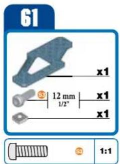
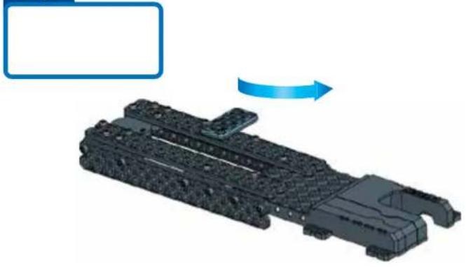
text_image
61 x1 12 mm 1/2" x1 x1 1:1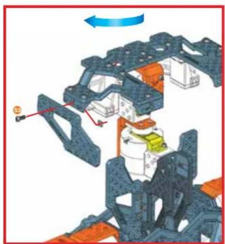
natural_image
Mechanical assembly diagram showing a multi-stage frame with highlighted components and directional arrows (no text or symbols)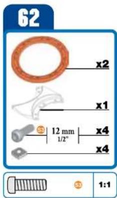
text_image
62 x2 x1 $ 12 mm 1/2" x4 x4 $ 1:1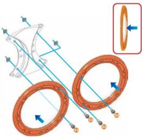
text_image
Technical diagram illustrating mechanical components with labeled parts S3, S4, S5, and a magnified inset showing rotational direction.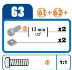
text_image
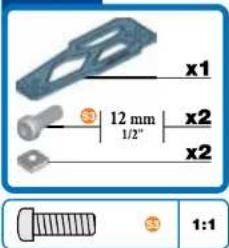
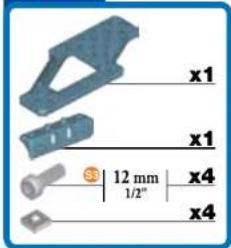
63 61 + 62 + S 12 mm x2 1/2" x2 1:1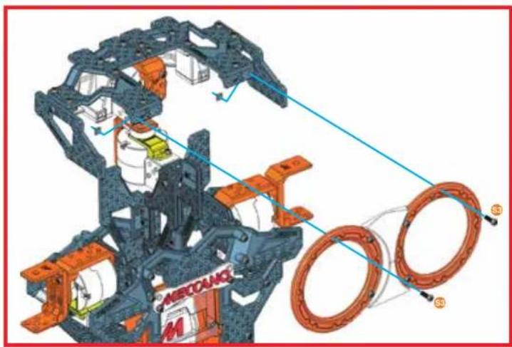
natural_image
3D mechanical assembly diagram showing components like a car body frame and two circular rings with labeled parts (no readable text or symbols)
natural_image
Illustration of a mechanical robot with large circular eyes and orange accents, no visible text or symbols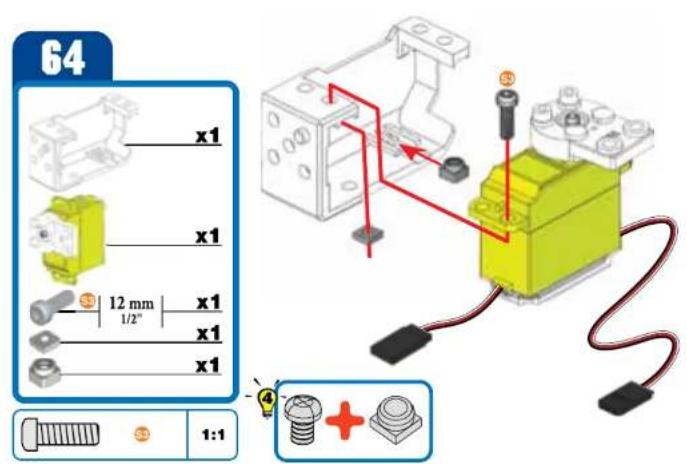
text_image
64 x1 x1 12 mm x1 1/2" x1 x1 x1 1:1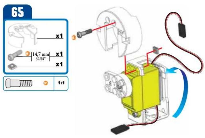
text_image
65 x1 37/64" 14,7 mm x1 x1 31 1:1
text_image
66 x1 38,1 mm x2 11/2" x2 1:1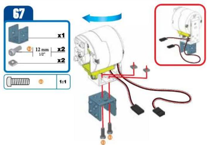
text_image
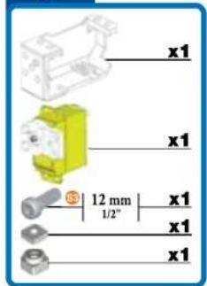
67 x1 12 mm x2 1/2" x2 1:1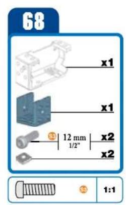
text_image
68 x1 x1 12 mm 1/2" x2 x2 1:1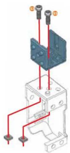
natural_image
Technical diagram of an electrical component with red wires and mounting points (no text or symbols)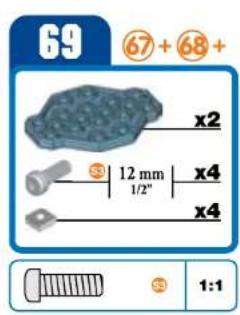
text_image
69 67 + 68 + x2 12 mm x4 1/2" x4 1:1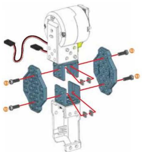
text_image
Technical diagram of an electrical component with labeled parts and red annotations indicating connections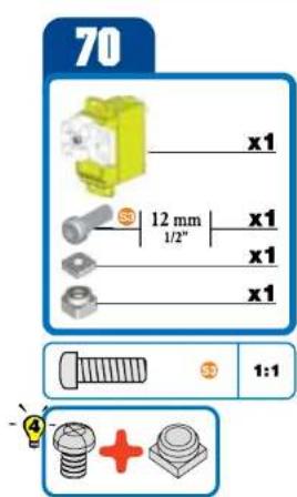
text_image
70 x1 12 mm x1 1/2" x1 x1 1:1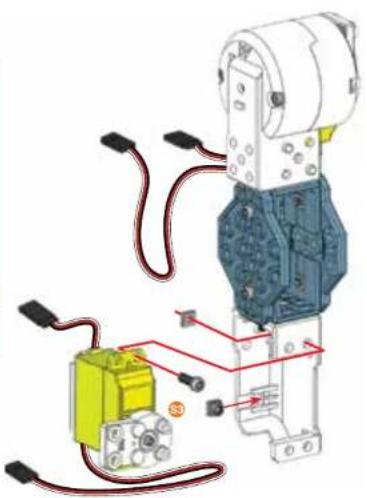
natural_image
Mechanical assembly diagram showing a motor connected to a yellow battery and wiring (no text or symbols visible)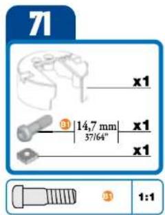
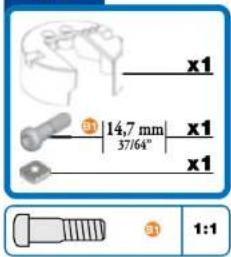
text_image
71 x1 31 14,7 mm x1 37/64" x1 1:1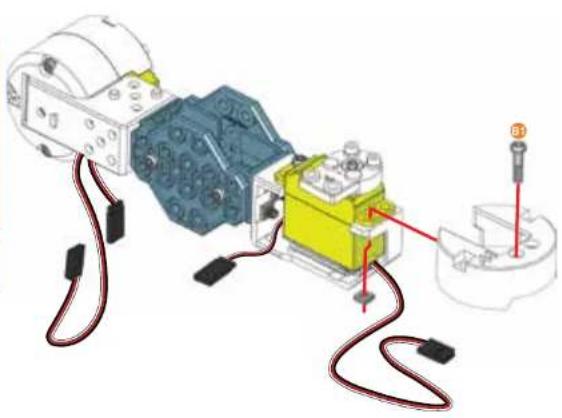
natural_image
Mechanical assembly diagram showing a motor connected to a yellow and blue component with red wiring, no visible text or symbols72
text_image
x1 38,1 mm | x2 1 1/2" x2
natural_image
Diagram of a mechanical assembly with wires and components, no visible text or symbols73
text_image
x1 x1 12 mm x1 1/2" x1
natural_image
3D mechanical assembly diagram showing orange and blue components with mounting holes (no text or symbols)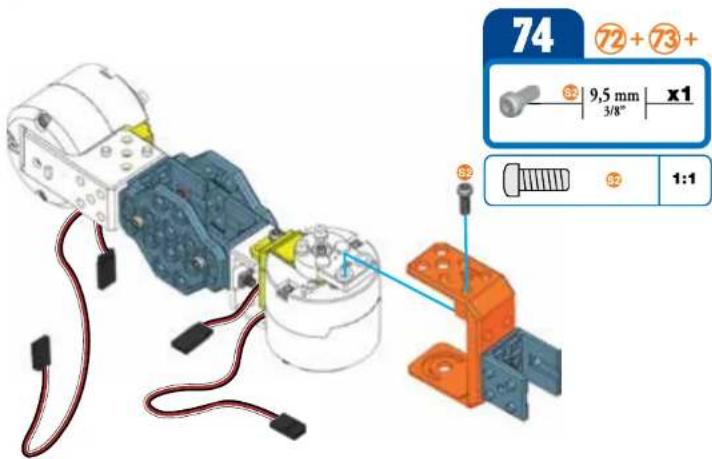
text_image
74 72 + 73 + 9,5 mm x1 3/8" 1:175
text_image
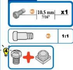
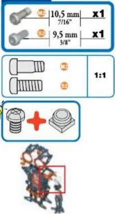
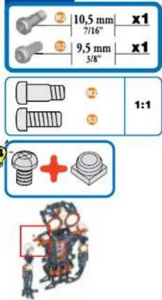
M2 10,5 mm x1 7/16° M2 1:1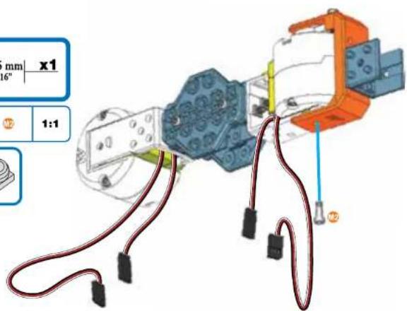
text_image
mm x1 16" 1:1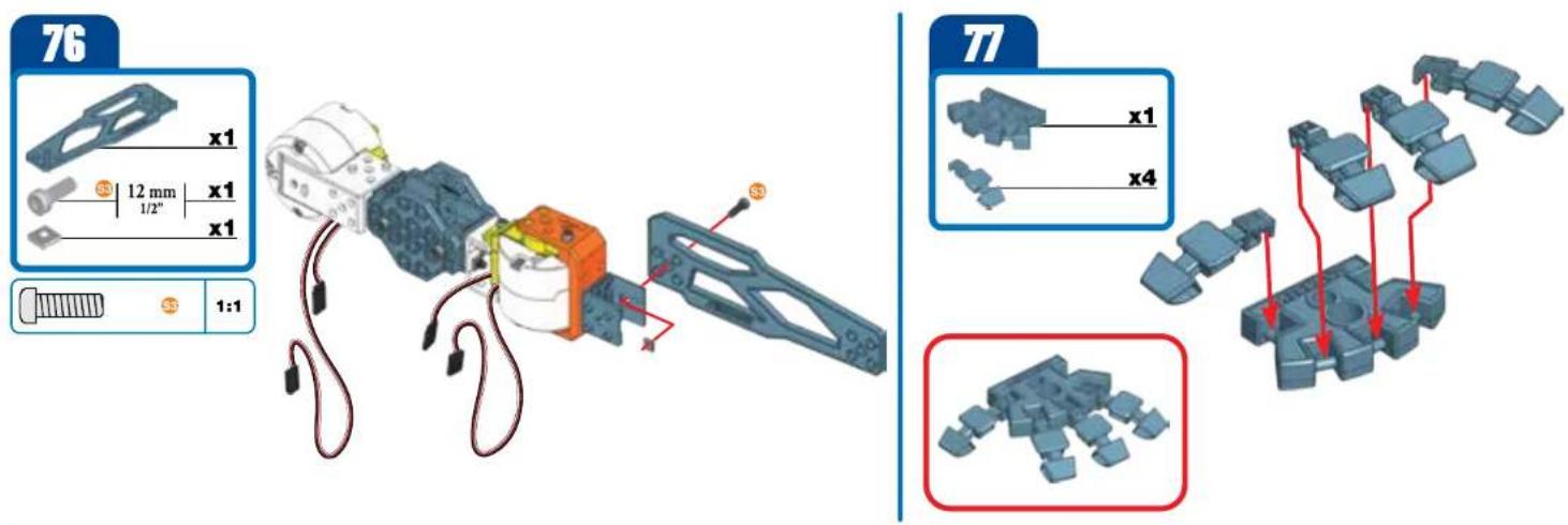
text_image
76 x1 12 mm x1 1/2" x1 1:1 77 x1 x4 x1 x4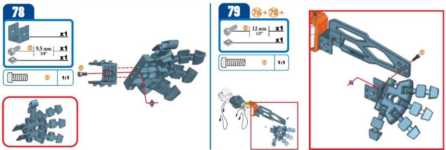
text_image
78 x1 9,5 mm x1 3/8" x1 1:1 79 76+78+ 12 mm x1 1/2" x1 1:1 S3 S3 S380
text_image
x1 12 mm 1/2" x2 x2 1:1
natural_image
Illustration of a robotic arm with sensors and a highlighted section (no text or symbols)
natural_image
Mechanical assembly diagram showing components with numbered parts (no text or symbols)81
text_image
10,5 mm x1 7/16" 9,5 mm x1 3/8" 1:1 +
text_image
10,5 mm x1 7/16" 9,5 mm x1 3/8" 1:1 +
text_image
Technical diagram of a mechanical assembly with numbered components, likely for assembly or maintenance instructions.82
text_image
x1 x1 12 mm 1/2" x1 x1
text_image
x1 x1 12 mm 1/2" x1 x1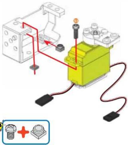
text_image
Diagram showing a mechanical assembly with labeled components and wiring, including a yellow robotic arm and a blue screw with red indicator lights.83
text_image
x1 ③ 14,7 mm | x1 37/64" x1 1:1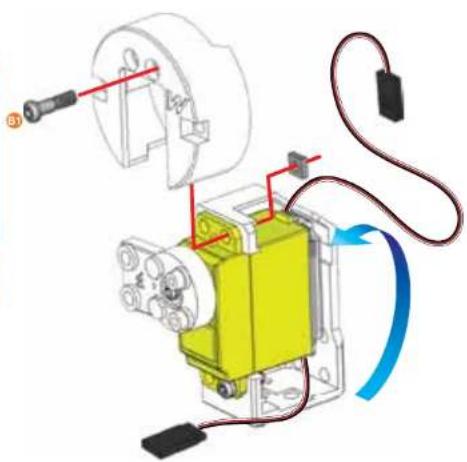
natural_image
Mechanical assembly diagram showing a yellow component connected to a motor with wiring and a blue curved arrow indicating motion (no text or symbols present)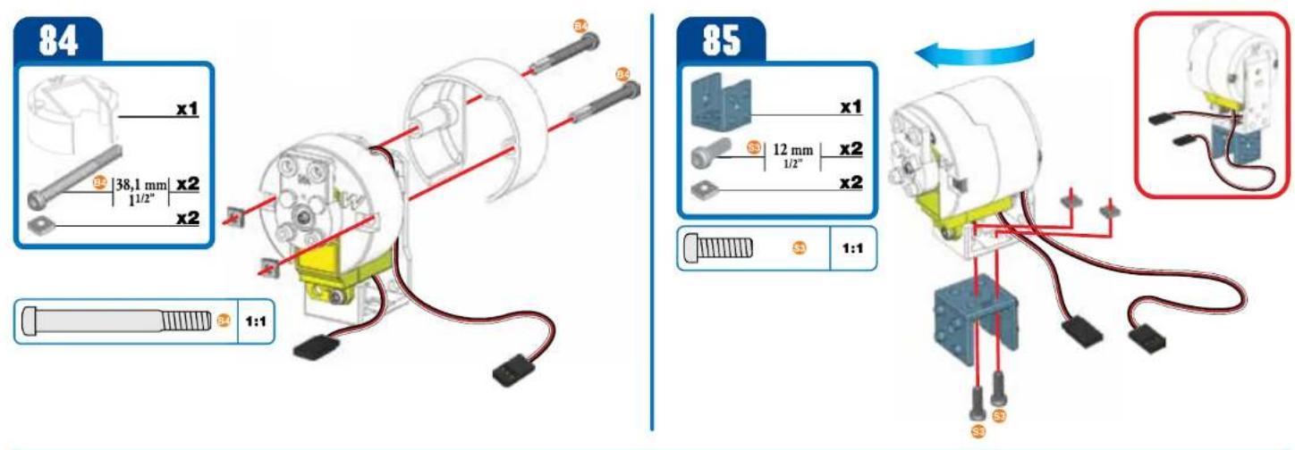
text_image
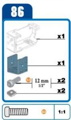
86 x1 x1 12 mm 1/2" x2 x2 1:1
text_image
Technical diagram showing a mechanical assembly with labeled components and red wiring connections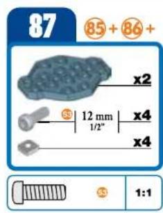
text_image
87 85 + 86 + x2 12 mm x4 1/2" x4 1:1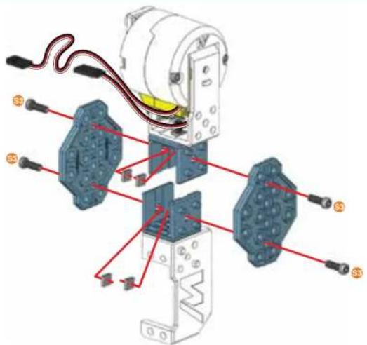
text_image
Technical diagram of a mechanical assembly with labeled components and red wiring connections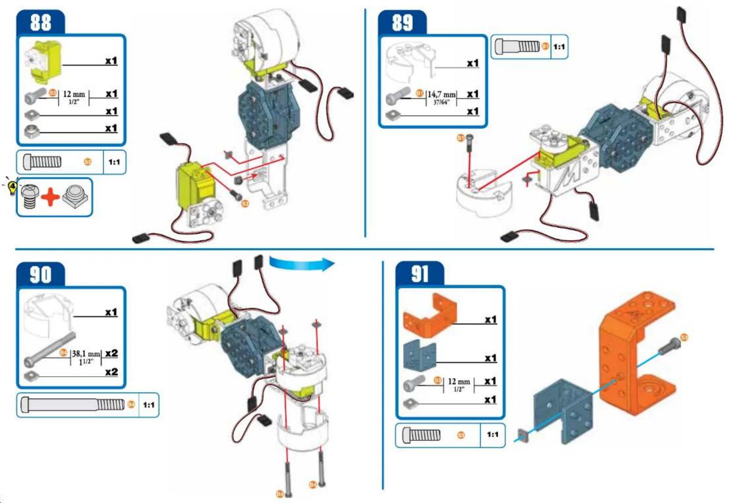
text_image
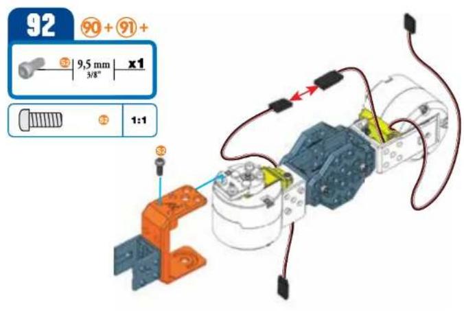
92 90 + 91 + 5 9,5 mm x1 3/8" 1:1 3 5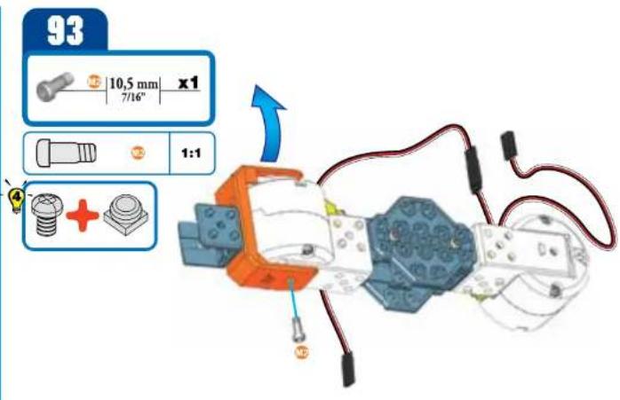
text_image
93 10,5 mm x1 7/16" 1:1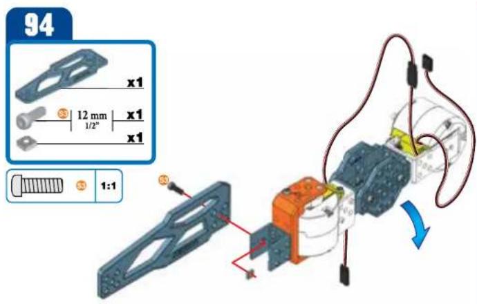
text_image
94 x1 12 mm x1 1/2" x1 1:1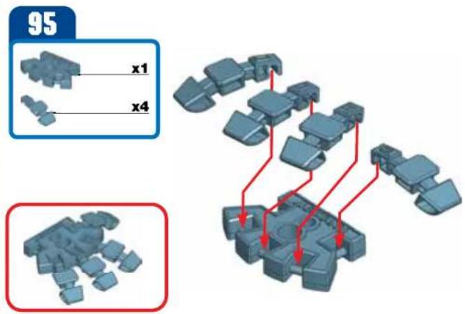
text_image
95 x1 x496
text_image
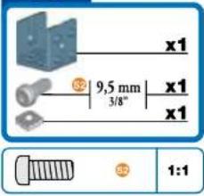
x1 9,5 mm 3/8" x1 x1 1:1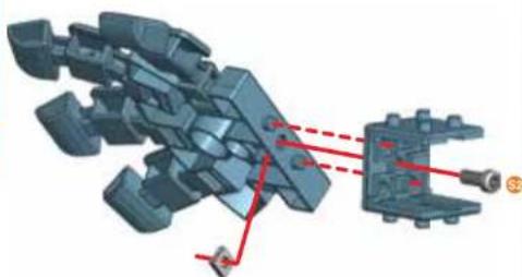
natural_image
3D mechanical assembly diagram showing a complex mechanical component with red dashed lines indicating alignment or connection points (no text or symbols present)97
text_image
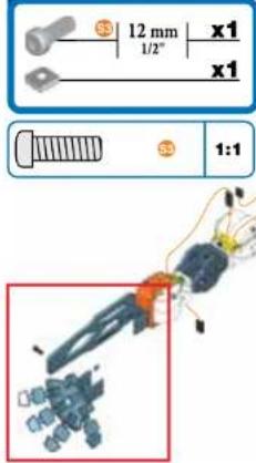
12 mm x1 1/2" x1 1:1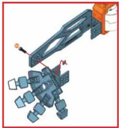
natural_image
Mechanical assembly diagram showing a robotic arm interacting with a multi-body mechanical component (no text or symbols visible)98
text_image
x1 12 mm 1/2" x2 x2 1:1
natural_image
Mechanical assembly diagram showing a frame with labeled components and wiring (no readable text or symbols)99
text_image
10,5 mm 7/16" 9,5 mm 3/8" x1 x1 1:1 12 32 +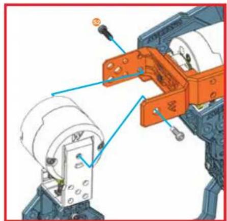
natural_image
Mechanical assembly diagram showing a robotic arm with orange components and blue alignment arrows (no text or symbols)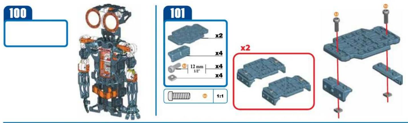
text_image
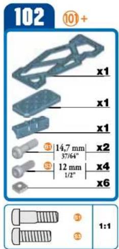
102 ⑩+ x1 x1 x1 ⑪ 14,7 mm 37/64" ⑤ 12 mm 1/2" x2 x4 x6 ① ② ③ 1:1
text_image
Technical diagram of a mechanical assembly with numbered components and red alignment lines indicating alignment or assembly.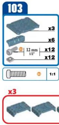
text_image
103 x3 x6 12 mm 1/2" x12 x12 1:1 x3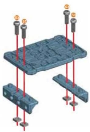
natural_image
3D diagram of a blue plastic mold with red pins and mounting points (no text or symbols)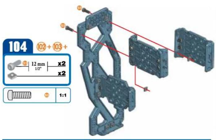
text_image
104 102 + 103 + 12 mm x2 1/2" x2 1:1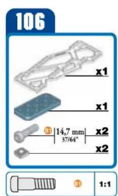
text_image
106 x1 x1 3 | 14,7 mm | x2 3 57/64" x2 x2 3 1:1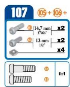
text_image
107 105 + 106 + 14,7 mm x2 37/64" 12 mm x2 1/2" x4 1:1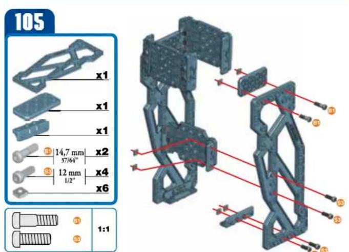
text_image
105 x1 x1 x1 3 14,7 mm x2 37/64" 3 12 mm x4 1/2" x6 1:1
natural_image
3D mechanical assembly diagram showing a frame structure with red alignment lines and numbered components (no text or symbols)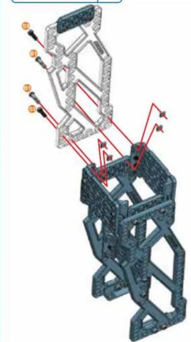
text_image
Technical diagram of a mechanical assembly with numbered components and red directional arrows indicating motion or force vectors.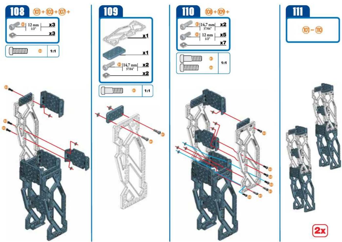
112
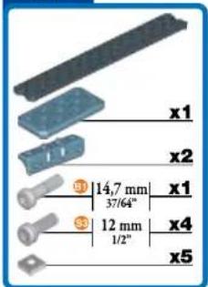
text_image
x1 x2 ① 14,7 mm 37/64° ③ 12 mm 1/2" x4 x5
natural_image
3D diagram of a mechanical assembly with red rods and labeled points (S1, S2, S3), no readable text or symbols present.113
text_image
x1 12 mm 1/2" x1 x1 1:1
natural_image
3D mechanical assembly diagram showing a blue component mounted on a textured gray plate with a red vertical line and a small inset detail (no text or symbols)114
text_image
x1 12 mm 1/2" x2 x1 x1
natural_image
3D mechanical assembly diagram showing a lever and wheel with mounting points (no text or symbols)115
text_image
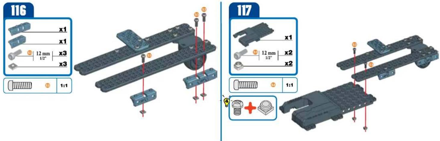
x1 12 mm 1/2" x2 x1 x1
natural_image
3D mechanical assembly diagram showing two parallel plates with red alignment lines and mounting points (no text or symbols)
text_image
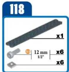
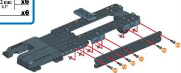
118 x1 12 mm 1/2" x6 x6
text_image
2 mm x6 1/2" x6 S3 S3 S3 S3 S3 S3 S3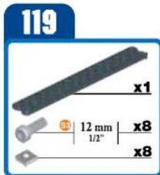
text_image
119 x1 3 12 mm 1/2" x8 x8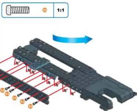
text_image
1:1 S3 S3 S3 S3 S3120
natural_image
3D rendering of a mechanical component with a blue arrow indicating rotational motion (no text or symbols)121
text_image
12 mm x2 1/2" x2 1:1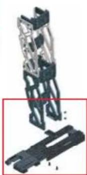
natural_image
Mechanical assembly diagram showing a bracket and housing (no text or symbols visible)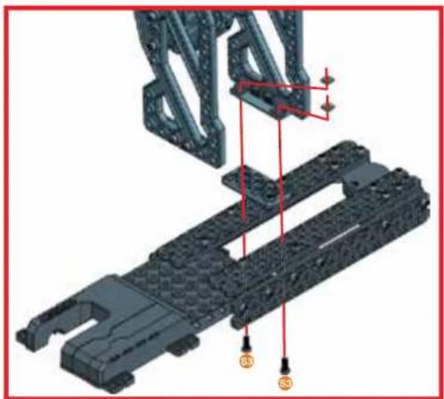
natural_image
3D mechanical assembly diagram showing a bracket with mounting holes and red alignment lines (no text or symbols)122
text_image
x1 x1 x2 x2
natural_image
Mechanical assembly diagram showing a vehicle chassis with attached components and a red curved arrow indicating rotation (no text or symbols)123

text_image
34 35 36 37 12 mm 1/2" x1 x2 x4 x4 x2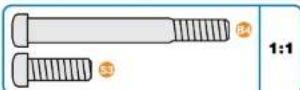

text_image
Technical diagram of a mechanical assembly with labeled components and colored trajectory lines124
natural_image
Mechanical assembly diagram showing a structural component with red arrows indicating motion or force direction (no text or symbols present)125
natural_image
3D mechanical assembly diagram showing structural components with red alignment lines (no text or symbols)126
text_image
x1 x1 12 mm x4 x4 1/2"
natural_image
Mechanical assembly diagram showing structural components and light paths (no text or symbols)127
natural_image
Mechanical assembly diagram showing a tracked vehicle with red trajectory lines and mounting points (no text or symbols)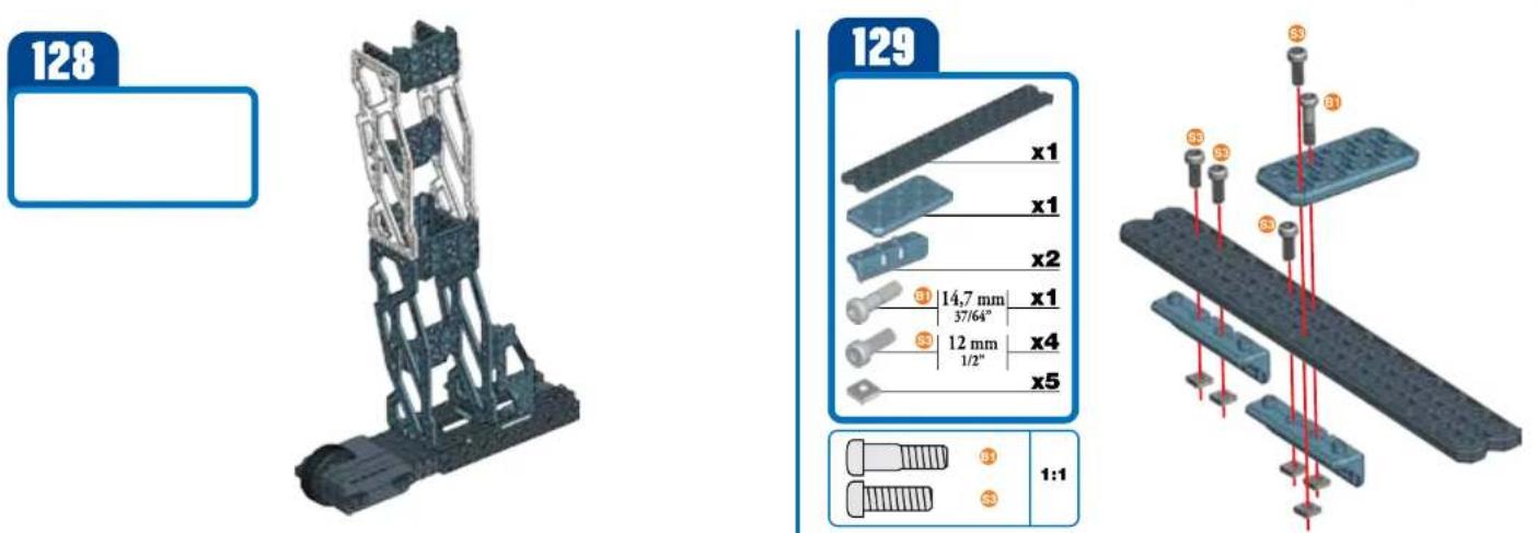
130
natural_image
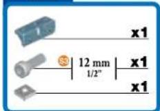
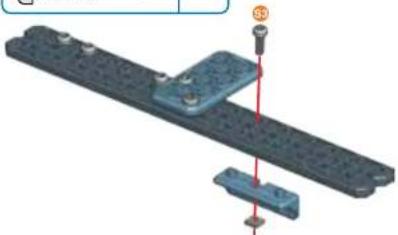
3D mechanical assembly diagram showing a blue component mounted on a gray plate with a red vertical line and bolted connection (no text or symbols)131
text_image
x1 12 mm 1/2° x2 x1 x1

text_image
Technical diagram showing assembly of a mechanical component with labeled parts and exploded view of components132
text_image
x1 12 mm 1/2" x2 x1 x1
135
text_image
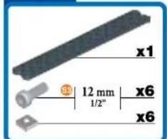
x1 12 mm 1/2" x6 x6
text_image
12 mm x6 1/2" x6 S3 S3 S3 S3 S3 S3136
text_image
x1 12 mm x8 1/2" x8 1:1137
natural_image
3D model of a futuristic vehicle with a blue arrow indicating motion direction (no text or symbols)138
text_image
12 mm x2 1/2" x2 1:1
natural_image
3D mechanical assembly diagram showing a frame structure with labeled points S1, S2, and S3 (no text or symbols beyond labels)139
text_image
x1 x1 x2 x2
natural_image
Mechanical assembly diagram showing a motor, gear, and housing with red directional arrow indicating motion (no text or symbols)140
text_image
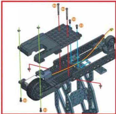
34 38,1 mm x2 11/2" 33 12 mm x4 1/2" 12 mm x4 x1 x2
text_image
1:1 +
text_image
Technical diagram of a vehicle chassis with labeled components and colored wiring, likely for assembly or maintenance instructions.141
text_image
33 12 mm x2 1/2" x2 33 1:1
natural_image
Mechanical assembly diagram showing a component with red arrows indicating motion or force, no visible text or symbols142
text_image
x1 12 mm 1/2" x2 x2 1:1
natural_image
3D mechanical assembly diagram showing structural components with red arrows indicating force or movement (no text or symbols)143
text_image
x1 x1 3 12 mm 1/2" x4 x4 1:1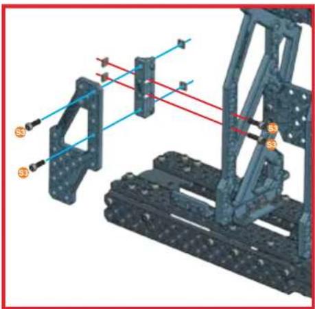
natural_image
Mechanical assembly diagram showing a frame structure with blue alignment lines and orange connectors (no text or symbols)144
text_image
12 mm x1 1/2" x1 1:1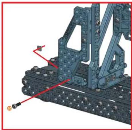
natural_image
Mechanical assembly diagram showing a tracked vehicle with attached components and red alignment lines (no text or symbols)145
natural_image
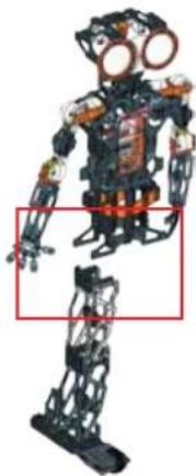
Mechanical assembly with articulated arms and a vertical frame (no visible text or symbols)146

natural_image
Mechanical robot with exposed mechanical joints and orange headgear, shown in a standing pose (no text or symbols visible)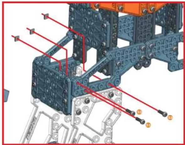
natural_image
Technical diagram of a mechanical assembly with blue structural elements and red wiring (no text or labels)147

natural_image
Mechanical humanoid robot with articulated joints and exposed mechanical components (no visible text or symbols)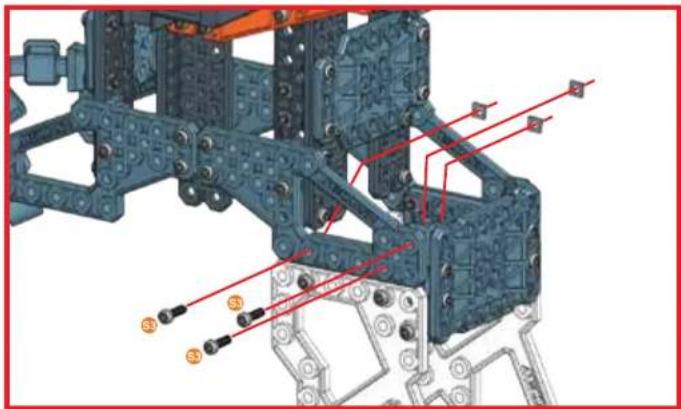
natural_image
Mechanical assembly diagram showing structural components with red annotations and orange connectors (no readable text or symbols)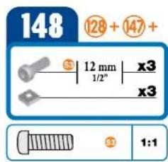
text_image
148 ⑫28 + ⑭47 + S | 12 mm | x3 1/2" x3 ③ 1:1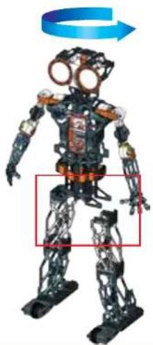
natural_image
Mechanical humanoid robot with exposed mechanical joints and a blue rotation arrow, no visible text or symbols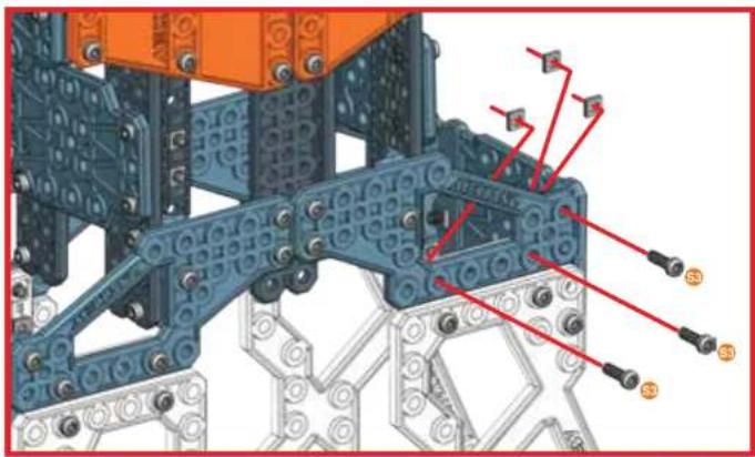
natural_image
Mechanical assembly diagram showing blue and gray components with red connectors (no text or symbols)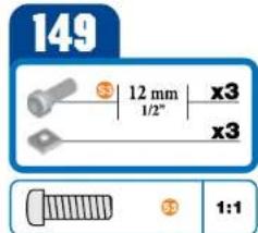
text_image
149 3 12 mm x3 1/2" x3 3 1:1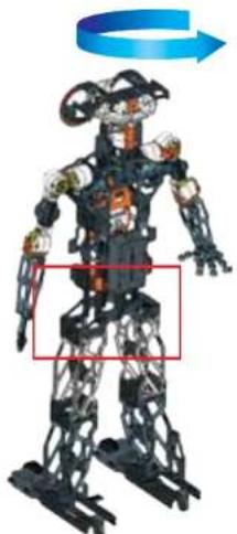
natural_image
3D model of a humanoid robot with exposed mechanical joints and a blue arrow indicating rotation (no text or symbols)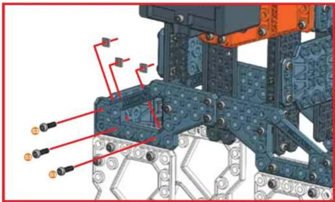
text_image
Technical diagram of a mechanical assembly with labeled components and red annotations indicating parts of each part.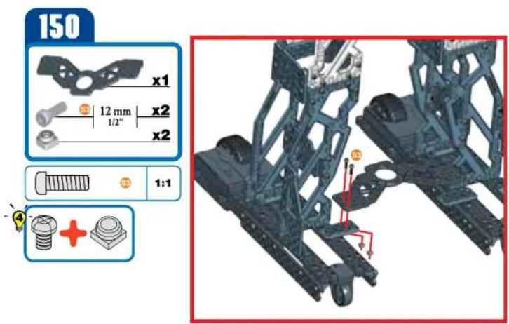
text_image
150 x1 12 mm x2 1/2" x2 1:1 +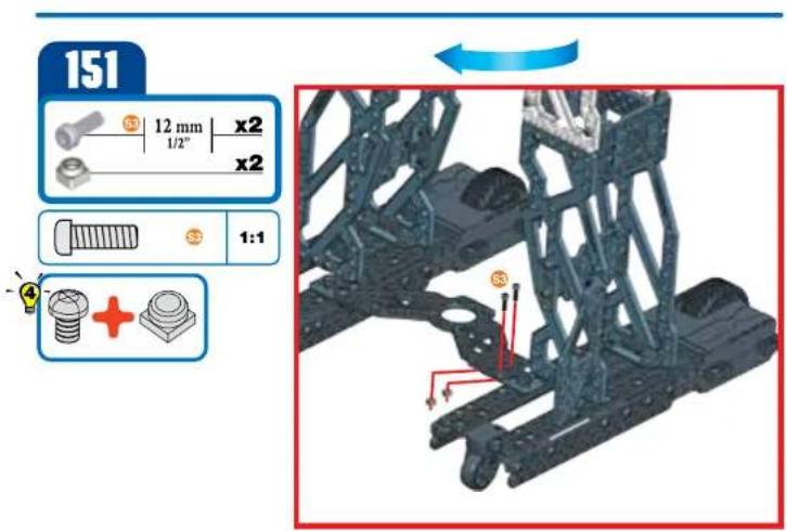
text_image
151 12 mm x2 1/2" x2 1:1 + +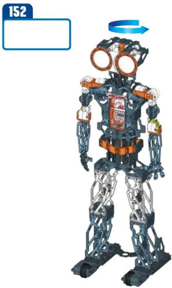
natural_image
Illustration of a humanoid robot with exposed mechanical joints and orange visor, no text or symbols present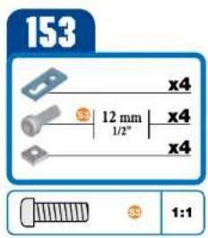
text_image
153 x4 12 mm 1/2" x4 x4 1:1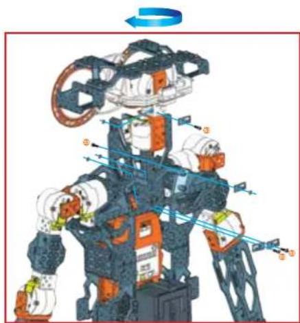
natural_image
Illustration of a robotic humanoid robot with dynamic motion arrows and labeled components (no text or symbols)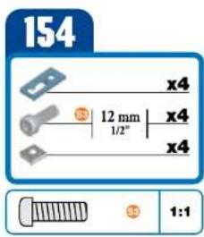
text_image
154 x4 12 mm 1/2" x4 x4 1:1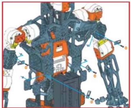
natural_image
Illustration of a robotic arm with dynamic joint movements and control buttons (no text or symbols)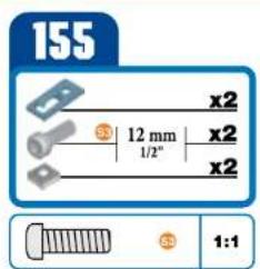
text_image
155 x2 12 mm 1/2" x2 x2 1:1
natural_image
3D mechanical assembly diagram showing structural components with no visible text or symbols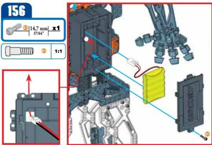
text_image
156 ③ 14,7 mm x1 37/64" 1:1 ABEYANS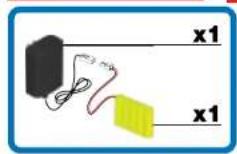
NOTE:
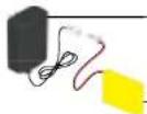
HOW TO CHARGE MECCANOID G15KS
- Disconnect and remove battery
from Meccanoid ^TM - Connect battery charger connector into battery pack
- Plug adapter into a standard wall outlet
- Charge is complete when light on battery charger turns green.
REMARQUE
MISE EN CHARGE DU MECCANOID G15KS
-
Open the battery door with a Meccano tool.
-
DO NOT remove or install batteries using sharp or metal tools. 3. Install battery pack as shown. 4. Replace battery door securely. 5. Check your local laws and regulations for correct recycling and/or battery disposal.
F INSTALLATION DES PILES
natural_image
Interior corner diagram showing a black cylindrical device connected to a wall-mounted power outlet and a yellow strip, with no visible text or symbols.- Use only the included charger.
- Utiliser uniquement le charpeur inclus.
- Utilice únicamente el cargador incluido.
- Nur das mitgelieferte Ladegerät verwenden.
- Gebruik uitsluitend de meegeleverde oplader.
- Utilizzare solo il caricabatteria incluso.
- Utilize somente o carregador incluso.
- Используйте только зарядное устройство, входящее в комплект.
The toy is only to be connected to Class I equipment bearing the symbol:
GB Meccanoid comes programmed to speak in English*. If you are satisfied with my language, turn to the next page.
• To change my language, go to www.meccano.com and find your language.
• Download the Robot Update software
- Locate the included USB cable
- Connect USB cable to computer
- Insert micro USB end into the port on the MeccaBrain™
*U.K. English also available.
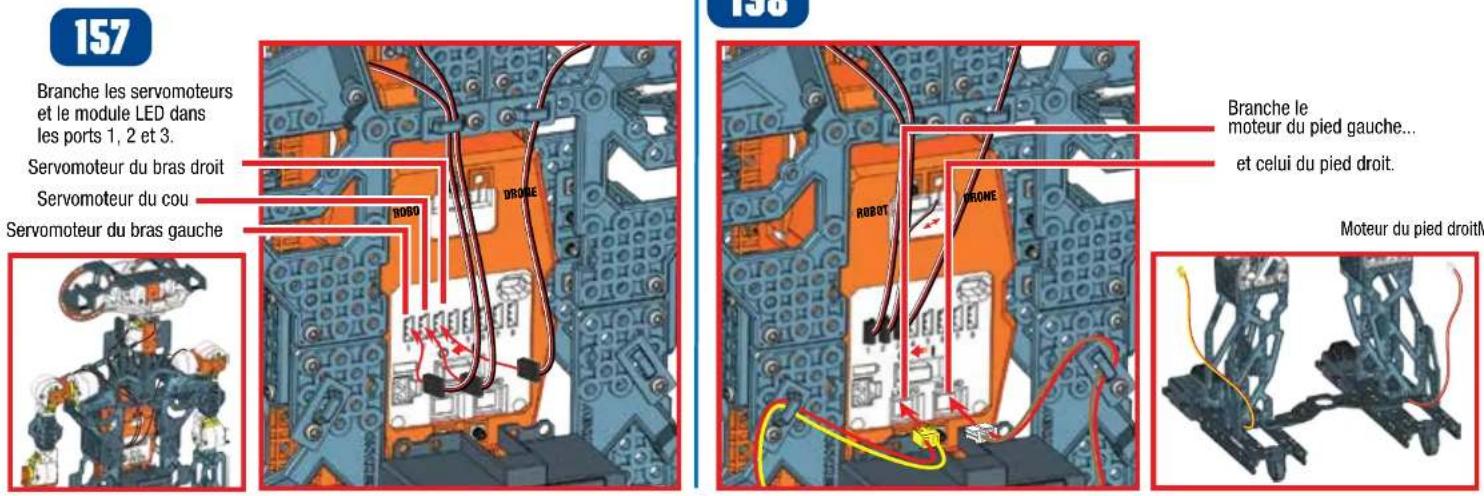
LED module into ports
1,2 and 3
Right Arm Servo
Neck Servo
Left Arm Servo
158
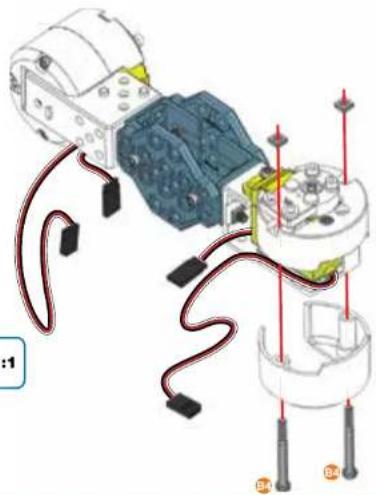
Plug in
left foot motor
and right foot motor.
Left Foot Motor
Right Foot Motor
159
Plug in battery cable
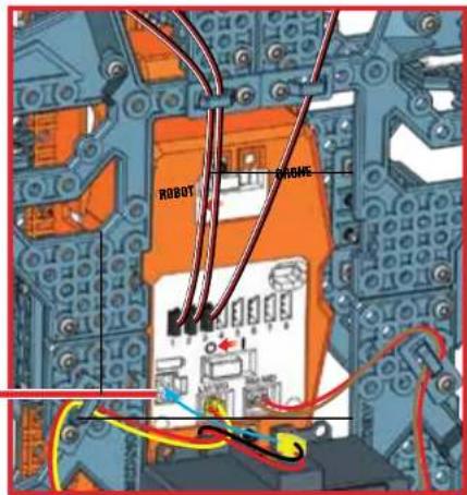
text_image
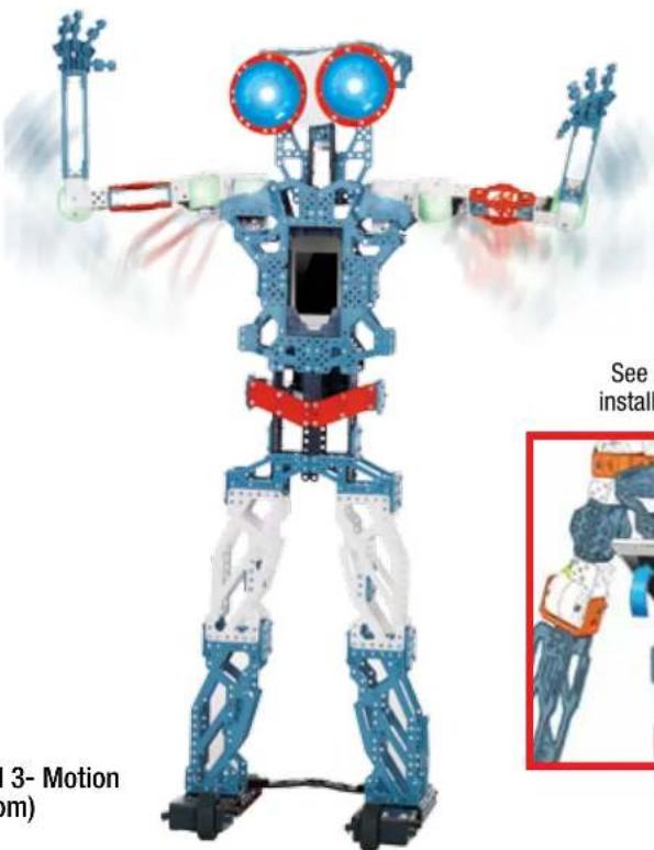
ROBOT PHONE160
Make sure robot is in robot mode
Turn robot on
Well done, your build is complete.
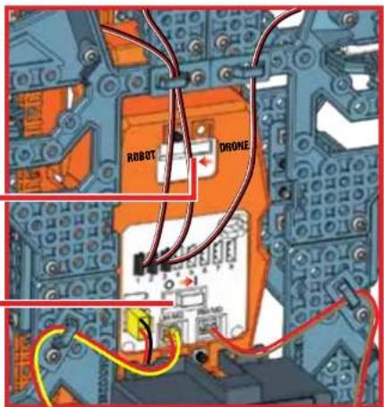
text_image
ROBOT DRONEB
PLAY
3.1 LET'S PLAY
1 Meccanoid will start speaking and do a systems check to verify connections.
2 If connections are correct, the robot will restart, ask for your name, and then introduce himself.
Note: If connections are not correct, the robot will let you know. Return to step 157 and review connections.
3 Meccanoid will ask you to test its voice commands. Listen for the directions.
4 Say "Meccanoid," then wait for the beep, wait for his eyes to turn GREEN, then say "Tell me a joke".
Eye color communicates mode
When the Robot's eye's are BLUE, he is listening for "Meccanoid" (or custom name).

After hearing his name, his eyes will turn GREEN. Now say any Main Menu command.

text_image
MeccaBrain™ Microphone GREEN L.I.M. Library BLUE No/Exit YELLOW Yes/Save RED Record L.I.M. MECCANO SpeakerTIP: Press any button when they are all unlit for help. The robot will also tell you about its button functions.
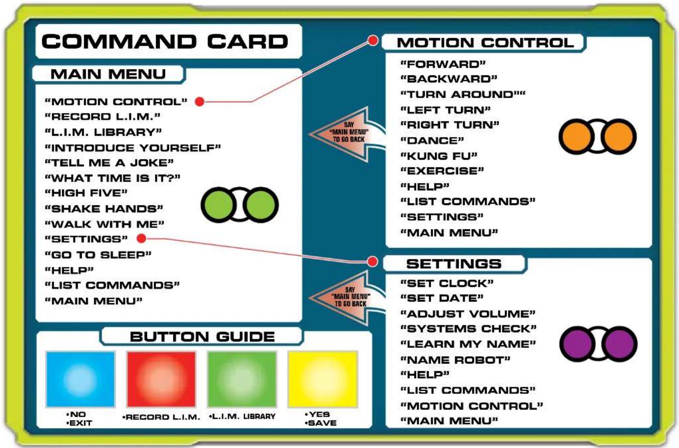
3.2 COMMAND CARD
VOICE CONTROL TIPS
1 When the robot's eyes are BLUE, he is listening for "Meccanoid" (or his custom name if it has been changed).
2 Then say "Main Menu", "Motion Control" or "Settings" to navigate between the three voice command sections, shown below.
3 Then you can say a voice command from the section that you have selected.
4 Speak clearly when giving a voice command. Not too fast, not too slow.
5 Meccanoid cannot listen and speak at the same time, so make sure he's done speaking before giving a voice command.
flowchart
graph TD
    A["COMMAND CARD"] --> B["MAIN MENU"]
    B --> C["MOTION CONTROL"]
    C --> D["RECORD L.I.M."]
    D --> E["L.I.M. LIBRARY"]
    E --> F["INTRODUCE YOURSELF"]
    F --> G["TELL ME A JOKE"]
    G --> H["WHAT TIME IS IT?"]
    H --> I["HIGH FIVE"]
    I --> J["SHAKE HANDS"]
    J --> K["WALK WITH ME"]
    K --> L["SETTINGS"]
    L --> M["GO TO SLEEP"]
    M --> N["HELP"]
    N --> O["LIST COMMANDS"]
    O --> P["MAIN MENU"]

    Q["MOTION CONTROL"] --> R["FORWARD"]
    R --> S["BACKWARD"]
    S --> T["TURN AROUND"]
    T --> U["LEFT TURN"]
    U --> V["RIGHT TURN"]
    V --> W["DANCE"]
    W --> X["KUNG FU"]
    X --> Y["EXERCISE"]
    Y --> Z["HELP"]
    Z --> AA["LIST COMMANDS"]
    AA --> AB["SETTINGS"]
    AB --> AC["MAIN MENU"]

    AD["BUTTON GUIDE"] --> AE["NO EXIT"]
    AE --> AF["RECORD L.I.M."]
    AF --> AG["L.I.M. LIBRARY"]
    AG --> AH["YES SAVE"]

    AI["SETTINGS"] --> AJ["SET CLOCK"]
    AJ --> AK["SET DATE"]
    AK --> AL["ADJUST VOLUME"]
    AL --> AM["SYSTEMS CHECK"]
    AM --> AN["LEARN MY NAME"]
    AN --> AO["NAME ROBOT"]
    AO --> AP["HELP"]
    AP --> AQ["LIST COMMANDS"]
    AQ --> AR["MOTION CONTROL"]
    AR --> AS["MAIN MENU"]
3.3 VOICE COMMANDS
1 When the Robot's eye's are BLUE, he is listening for "Meccanoid" (or custom name).

2 After hearing his name, his eyes will turn GREEN. Now say any Main Menu command.


Say: Introduce yourself\*

Meccanoid will: Introduce himself.

Say: List commands

Meccanoid will: List all voice commands available in the current mode.

Say: High five\*

Meccanoid will: Raise up his arm and ask for a high five.
Note: Gently but firmly push his hand back to give him

Say: Tell me a Joke\*

Meccanoid will: Tell a joke.

Say: Walk with me\*

Meccanoid will: Ask you to take his hand and lead him on a walk.
Note: Lift the robot's hand and he will start moving forward. When you are finished, drop Meccanoid's hand and he will stop.
natural_image
Three identical humanoid robot figures in motion, no visible text or symbols
Say: Motion control

Meccanoid: Eyes will turn orange and he will wait for your next command. Say one of these commands:
- Forward
- Backward
- Left Turn
• Right Turn - Turn Around
• Kung Fu* - Exercise*
• Dance* - Help
- Main Menu
- List Commands
Note: In this menu, you only need to say the command. For example, say "Forward" and Meccanoid will move forward.
Note: Say "List Commands" for available commands in this menu.

Say: Shake hands\*

Meccanoid will: Lift his right hand and ask you to shake hands

Say: What time is it?\*

Meccanoid will: Tell you the time. Note: You will first need to set the correct time in settings

Say: Record L-I-M

Meccanoid will: Tell you how to program using Learned Intelligent Movement, or L.I.M.™
L.I.M. ^™ allows you to create animations by physically moving the robot which you can then name and store in the L.I.M. ^™ library.

Say: L-I-M library

Meccanoid will: Allow you to play one of the recordings, in your L.I.M. library.

Say: Help

Meccanoid will: Tell current mode and gives helpful tips about the current mode.

Say: Main Menu

Meccanoid will: Exit to Main Menu.

Say: Settings

Meccanoid will: Eyes will turn purple and he will wait for your next command. Say one of these commands:

- Set Date
- Set Clock
- Learn my name
- Name Robot
- Systems Check
- Adjust Volume
• Help - Main Menu
- List Commands

Say: Go to sleep

Meccanoid will: Go to sleep Note: press any button to wake up Meccanoid.
TIP: Press any button when they are all unlit in order to freeze the robot. The robot will tell you about its button functions.
* Please note that the voice commands with an asterisk (*) beside them will not work in Drone mode. Drone mode is only for alternative builds and is not recommended for MeccaNoid when assembled as shown in this instruction manual.
To enter Drone mode, slide the mode switch to DRONE MODE.
3.4 PROGRAM WITH APP

text_image
DOWNLOAD FREE APP*MORE WAYS TO PLAY!
Download the free app and program Meccanoid with your smart device!
Program movements and/or sounds with:
1- Learned Intelligent Movement (LIM™) 2- Ragdoll 3- Motion Capture powered by Extreme Reality (www.xtr3d.com)
(2&3 require smart device [not included])
Free app available at www.meccano.com
IMPORTANT! CHECK WWW.MECCANO.COM TO SEE IF YOUR DEVICE IS COMPATIBLE.
(MAY NOT WORK WITH ALL DEVICES*)
*COMPATIBLE WITH SELECT IOS AND SELECT ANDROID DEVICES (SOLD SEPARATELY). CHECK WWW. MECCANO.COM FOR A LIST OF COMPATIBLE DEVICES AND SYSTEM REQUIREMENTS, TO DETERMINE IF YOUR DEVICE IS COMPATIBLE. SPIN MASTER RESERVES THE RIGHT TO WITHDRAW THE APPLICATION AT ANY GIVEN TIME AND WITHOUT NOTICE.


natural_image
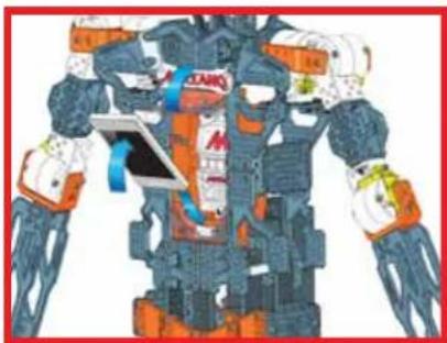
3D model of a humanoid robot with blue and white structural elements, no visible text or symbols on the robot itself.See below image for how to install smart device into cradle
natural_image
Illustration of a futuristic robot with dynamic arm and accessories (no visible text or symbols)Meccanoid communicates with your smart device through Bluetooth®
Bluetooth
Spin Master Inc., PMB #10053, 300 International Drive, Suite 100, Williamsville, NY 14221
Spin Master is not responsible for any damage caused to electronic devices through improper use. / Spin Master se saurait être tenu responsable des dommages causés aux appareils électroniques suite à une mauvaise utilisation. / Spin Master no se hace responsable de los darios causés en los dispositives électroniques por un uso indebida:/Spin Master haftet nicht für Schäden an elektronischen Geräten, die durch unsachgemäße Verwendung entstehen:/Spin Master is niet verantwortelijk voor enige schade aan elektronische apparatuur die is veroorzaakt door onjust gebruik. / Spin Master non è responsable per eventuali danni causati a dispositivi elettronici in seguito a uso improo. / Spin Master não è responsável por quaisquer danos causados a dispositivos électroniques por motivo de uso incorreto e/ou inapropriado. / Spin Master ne heсет ответственности за травleys, полученные при ненадлежащем использовании электронных устройств.
Apple, the Apple logo, iPhone, iPad, and iPod touch are trademarks of Apple Inc., registered in the U.S. and other countries. App Store is a service mark of Apple Inc. Google Play™ is a trademark of Google Inc.
The Bluetooth ^® word mark is a registered trademark owned by Bluetooth SIG, Inc. and any use of such mark by Spin Master Ltd. is under license.
2.2 RÉALISATION DES BRANCHEMENTS
157
natural_image
Three identical illustrations of a humanoid robot in full-body gear, standing upright (no text or symbols visible)
natural_image
Illustration of a futuristic robot with exposed mechanical components and dynamic motion lines (no text or symbols)natural_image
Three identical humanoid robot figures in motion, standing side by side (no text or symbols visible)
natural_image
Child's hands interacting with a smartphone displaying a small screen (no visible text or symbols)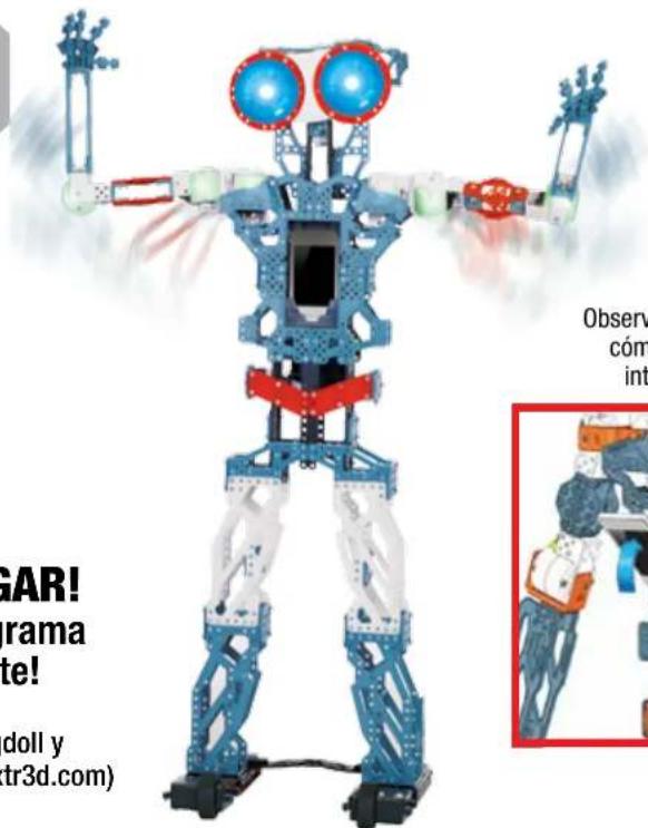
text_image
GAR! rama te! doll y tr3d.com) Observ cóm intnatural_image
Illustration of a futuristic robot with dynamic arm and mechanical components (no text or symbols)natural_image
Three identical humanoid robot figures in motion, standing upright with visible joints and limbs (no text or symbols)
natural_image
Illustration of a futuristic robot with dynamic arm and accessories (no visible text or symbols)ZEG "HOOFDMENU" OM TERUG TE GAAN
BEWEGINGSBESTURING
"VOORWAARTS"
"ACHTERWAARTS"
"DRAAI JE OM"
"BOCHT NAAR LINKS"
"BOCHT NAAR RECHTS"
"DANS"
"KUNG FU"
"DOE REK- EN STREK OEFENINGEN"
"HELP"
"TOON COMMANDO'S"
"INSTELLINGEN"
"HOOFDMENU"

ZEG "HOOFDMENU" OM TERUG TE GAAN
INSTELLINGEN
"STEL KLOK IN"
"STEL DATUM IN"
"PAS VOLUME AAN"
"CONTROLEER SYSTEMEN"
"LEER MIJN NAAM"
"GEEF ROBOT EEN NAAM"
"HELP"
"TOON COMMANDO'S"
"BEWEGINGSBESTURING"
"HOOFDMENU"
OVERZICHT VAN KNOPPEN

•NEE
•AFSLUITEN

•NEEM G-I-B OP •G-I-B BIBLIOTHEEK


•JA
•OPSLAAN

3.3 SPRAAKOPDRACHTEN
Zeg: Toon commando's

natural_image
Three identical humanoid robot figures in motion, one holding a weapon, with no visible text or symbols
natural_image
Illustration of a futuristic robot with dynamic gear and orange accents (no visible text or symbols)MEER MANIEREN OM TE SPELEN!
Spin Master Inc., PMB #10053, 300 International Drive, Suite 100, Williamsville, NY 14221
Bluetooth


2.2 COLLEGA I COMPONENTI ELETTRONICI
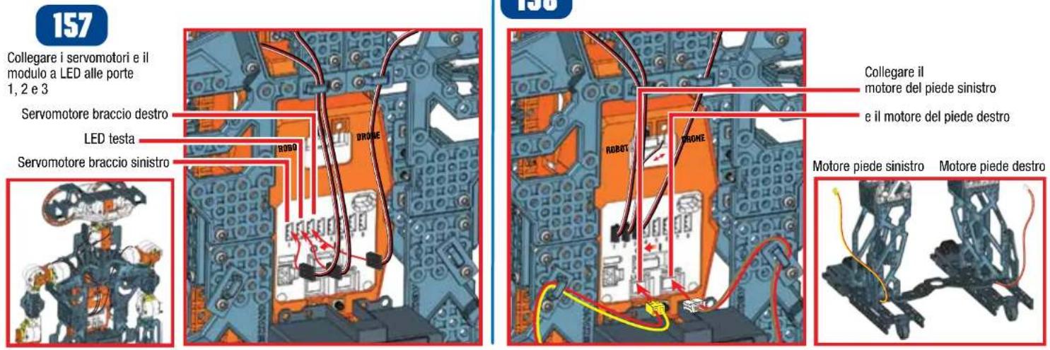
157
"IMPOSTA L'OROLOGIO"
"IMPOSTA LA DATA"
"REGOLA IL VOLUME"
"CONTROLLO DEL SISTEMA"
"IMPARA IL MIO NOME"
"NOME DEL ROBOT"
"AIUTO"
"LISTA COMANDI"
"CONTROLLO DEI MOVIMENTI"
"MENU PRINCIPALE"
GUIDA AI PULSANTI

•NO
•ESCI

•REGISTRA I COMANDI L.I.M.

•BIBLIOTECA L.I.M.

•Si
•SALVA

3.3 COMANDI VOCALI
natural_image
Child's hands interacting with a smartphone displaying a game interface (no visible text or symbols)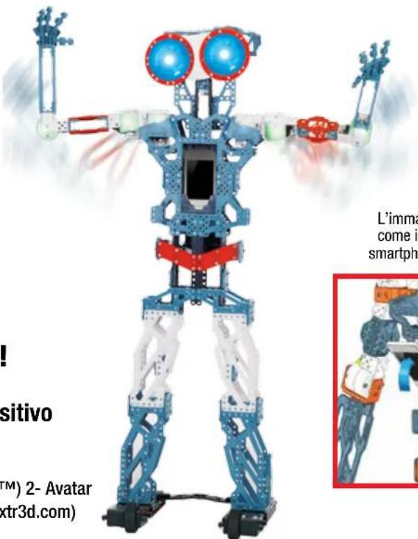
text_image
! positivo TM) 2- Avatar (xtr3d.com) L'imma come in smartphnatural_image
Illustration of a futuristic robot with dynamic arms and a tablet, no visible text or symbolsTANTI ALTRI MODI DI GIOCARE!
Spin Master Inc., PMB #10053, 300 International Drive, Suite 100, Williamsville, NY 14221
Bluetooth

Scarica su
App Store
DISPONIBILE SU
Google play
text_image
ROBOT PHONE160
text_image
RBOOT DRONE
ВОСПРОИЗВЕДЕНИЕ
3.1 ДАВАЙ ПОИГРАЕМ
natural_image
Three identical humanoid robot figures in motion, no visible text or symbolsnatural_image
Illustration of a futuristic robot with dynamic motion, featuring exposed mechanical components and a blue-tinted device (no text or symbols visible)Spin Master Inc., PMB #10053, 300 International Drive, Suite 100, Williamsville, NY 14221
Bluetooth


CONSUMER INFORMATION • INFORMATIONS DESTINÉES AU CONSOMMATEUR • INFORMACIÓN PARA EL CONSUMIDOR • VERBRAUCHERHINWEISE INFORMATIE VOOR GEBRUIKERS • INFORMAZIONI PER I CONSUMATORI • INFORMAÇÕES PARA O CONSUMIDOR • ИНФОРМАЦИЯ ДЛЯ ПОТРЕБИТЕЛЕЙ
GB BATTERY SAFETY INFORMATION:
- Requires 1 x Ni-MH 1800mAh battery pack (Included).
- Replacement of batteries must be done by adults.
- Promptly remove dead batteries from the toy.
- Dispose of used batteries properly.
- Remove batteries for prolonged storage.
- Only batteries of the same or equivalent type as recommended are to be used.
• DO NOT incinerate used batteries. - DO NOT dispose of batteries in fire, as batteries may explode or leak.
• DO NOT recharge non-rechargeable batteries.
• DO NOT short-circuit the supply terminals.
SPECIAL NI-MH BATTERY INSTRUCTIONS:
Requires 1 x Ni-MH 1800mAh battery pack. - Never charge battery unattended, - Charge battery in isolated area. Keep away from flammable materials. - Do not expose to direct sunlight. There is a risk of the batteries exploding, overheating, or igniting. - Do not disassemble, modify, heat, or short circuit the batteries. Do not place them in fires or leave them in hot places. - Do not drop or subject to strong impacts. - Do not allow the batteries or connectors to get wet. - Only charge the batteries with the specified Spin Master™ battery charger. - Only use the batteries in the device specified by Spin Master. - Carefully read the instruction guide and use the batteries correctly. - In the unlikely event of leakage or explosion use sand or a chemical fire extinguisher for the battery. - Batteries must be recycled or disposed of properly.
IMPORTANT INFORMATION: Remove all packaging before use. Retain this information, addresses and phone numbers for future reference. Content may vary from pictures. Meccano reserves the right to discontinue the website www.meccano.com at any time. Keep away from obstacles and electrical hazards.
SAFETY PRECAUTIONS: Parental guidance is recommended. Do not use Meccanoid on a table or near stairs; only use on the floor. Regularly examine for damage to the toy and sensors. In the event of any damage, remove from use. Keep hands, hair and loose clothing away from moving parts when power switch is turned ON. Turn OFF Meccanoid when not in use. During play, keep in sight so that you can supervise it all the time. Users should keep strict accordance with the instruction manual while operating the product.
CARE AND MAINTENANCE: This product is intended for indoor use only. Do not use outdoor - dirt, grass, cement will scratch the finish and/or block the sensors. Do not
submerge the toy in water. Do not play around water as this is a hazard and can cause a malfunction or damage the electronic assemblies. Keep the sensors clean, wipe with a scratchless cloth. Do not put any foreign objects in the USB port or sensors. Do not pull hard on any part of the robot as this may cause damage. TROUBLESHOOTING: If normal function of the product is disturbed or interrupted, strong electro-magnetic interference may be causing the issue. To reset product, turn it completely off, then turn it back on. If normal operation does not resume, move the product to another location and try again. To ensure normal performance, rechange the batteries, as low batteries may not allow full function.
F INFORMATIONS DE SÉCURITÉ RELATIVES AUX PILES :
GB Requires 1 x NI-MH 1800mAh battery pack (included). Batteries or battery packs must be recycled or disposed of properly. When this product has reached the end of its useful life it should not be disposed of with other household waste. The Waste Electrical and Electronic Equipment Regulations require it to be separately collected so that it can be treated using the best available recovery and recycling techniques. This will minimize the impact on the environment and human health from soil and water contamination by any hazardous substances, decrease the resources required to make new products and avoid using up landfill space. Please do your part by keeping this product out of the municipal waste stream! The "wheelie bin" symbol means that it should be collected as "waste electrical and electronic equipment". You can return an symbol means that it should be collected as "waste electrical and electronic equipment". You can return an old product to your retailer when you buy a similar new one. For other options, please contact you local council.
GB. Spin Master International SARL, hereby declares that this Meccanoid G15KS is in compliance with the essential requirements and other relevant provisions of Directive 1999/5/EC. A copy of the declaration of conformity can be requested through customercare@spinmaster.com or SPIN MASTER INTERNATIONAL S.A.R.L., 16 Avenue Pasteur, L-2310, Luxembourg.
Spin Master Inc., PMB #10053, 300 International Drive, Suite 100, Williamsville, NY 14221
Meets CPSC safety standards.
TM & © 2015 MECCANO for packaging, instructions and models built with this set. © MECCANO is an exclusive trademark of MECCANO. Spin Master logo is a trademark of Spin Master Ltd. All rights reserved. Patent pending.
Imported into EU by
Spin Master International
S.A.R.L., 16 Avenue Pasteur
L-2310, Luxembourg.
www.spinmaster.com
MADE IN CHINA / FABRIQUÉ EN CHINE / HECHO EN CHINA T91764_0002_20069908_GML_IB_R1_W_MEC_Meccanoid G15KS localized version