GPS - Remote control toy MULTIPLEX - Free user manual and instructions
Find the device manual for free GPS MULTIPLEX in PDF.

| Product type | GPS receiver for RC models |
| Brand | Multiplex |
| Model | GPS |
| Dimensions (L x W x H) | 60.5 x 20.0 x 16.0 mm |
| Weight (with cables) | 16 g |
| Power supply | Via M-LINK receiver (operating voltage not specified, consumption approx. 80 mA) |
| Integrated buffer battery | Yes |
| GPS receiver | Ultra-sensitive 50-channel |
| Antenna | Helix 4-wire circularly polarized, quasi-omnidirectional |
| Operating frequency | 1.58 GHz (civil GPS band) |
| Cold start | Approx. 1 minute |
| Hot start | Approx. 10 seconds |
| Update interval | 2 Hz |
| Accuracy (optimal conditions) | Position: approx. 2.5 m; Speed: approx. 0.1 m/s |
| Accuracy (normal conditions) | Position: approx. 5-10 m; Speed: approx. 0.5-1 m/s |
| Main functions | Speed (3D/2D), altitude, distance (3D/2D), distance traveled, azimuth, heading, alarms, min/max/average values |
| Transmitter compatibility | ROYALevo, ROYALpro (M-LINK), COCKPIT SX M-LINK (from V3.06), Multiplex telemetry display |
| Configuration | Via MULTImate (# 8 2094) or MULTIPLEX Launcher PC software (free) + USB cable (# 8 5149) |
| Temperature range | -20 °C to +55 °C |
| Recommended mounting | Antenna facing upward, avoid conductive materials (carbon, metal), attach with hook-and-loop tape, protect from vibrations |
| Maintenance and cleaning | No special maintenance; protect from moisture and shocks |
| Safety instructions | Read the manual before use; use only for modeling; comply with operating conditions; do not expose to excessive vibrations |
| Spare parts / Repairability | Not specified; limited warranty; in case of issues, contact dealer |
| General information | Uses US civil GPS system; fixed point automatically set at startup; model type adjustable (slow/fast) to optimize display |
Frequently Asked Questions - GPS MULTIPLEX
- Address 9: Ground speed in km/h (3D)
- Address 10: Altitude in meters relative to the fixed point
- Address 11: Distance in meters (3D) from the fixed point
- If the GPS is not moving, the fixed point is the current position.
- If the GPS is moving, it retains the last recognized high-precision position.
User questions about GPS MULTIPLEX
0 question about this device. Answer the ones you know or ask your own.
Ask a new question about this device
Download the instructions for your Remote control toy in PDF format for free! Find your manual GPS - MULTIPLEX and take your electronic device back in hand. On this page are published all the documents necessary for the use of your device. GPS by MULTIPLEX.
USER MANUAL GPS MULTIPLEX
Elongation / Elongation
Elongation / Elongation
These operating instructions are an integral part of the product, and contain important information and safety notes. For this reason please keep them readily accessible, and be sure to pass them on to the new owner if you ever dispose of the product.
-
SPECIFICATION
-
COMPATIBLE OUTPUT DEVICES
| Order No. # 8 5417 | |
| GPS receiver | High-sensitivity GPS receiver with fifty channels |
| Aerial | Four-core circular polarised helical aerial for virtually omni-directional reception |
| Data output (base functions / default settings) | Address / screen line 9: Spatial groundspeed (3D) in km/hr Address / screen line 10: Altitude above fixed point in metres (m) Address / screen line 11: Spatial distance (3D) to fixed point in metres (m) |
| Cold-start time under normal reception conditions | approx. 1 minute |
| Warm-start time under normal reception conditions | approx. 10 seconds |
| Buffer battery | yes, integral |
| Accuracy under optimum reception conditions | approx. 2.5 m (position) / approx. 0.1 m/s (speed) |
| Accuracy under normal reception conditions | approx. 5 - 10 m / approx. 0.5 - 1 m/s |
| Sampling rate | 2 Hz |
| Current drain | approx. 80 mA |
| Dimensions (L x W x H) | 60.5 x 20.0 x 16.0 mm |
| Temperature range | - 20°C ... + 55°C |
| Weight (incl. leads) | 16 g |
- SAFETY NOTES
Read right through these instructions before use.
Use only for the intended purpose ( 3)
Observe the installation notes ( 7)
Protect the GPS unit from vibration.
- APPLICATION
The MULTIPLEX GPS for M-LINK receivers (hereinafter "GPS") has been developed exclusively for modelling applications. It is prohibited to use the unit for industrial applications or in man-carrying equipment or vehicles.
4. BASICS, MEASURING PRINCIPLE
The MULTIPLEX GPS for M-LINK receivers provides a means of obtaining interesting information direct from your model.
At last you can actually see values such as the model's current airspeed, its altitude above the launch site, and its distance!
It is also possible to obtain values for other individual parameters such as the total distance covered by the model, and various angular information. Warning thresholds can be set on the GPS, and a variety of minimum, maximum and average values can be displayed.
The GPS is based on the same measuring principle as satellite navigation. It exploits the civilian service of the U.S. Global Positioning System "GPS".
The measurement of position and speed by means of GPS is based on more than 24 satellites which circle the world on precisely determined paths, each orbit taking 11 hours and 58 minutes. Each satellite contains at least one extremely accurate time-base (atomic clock), which is monitored and synchronised by fixed stations on Earth.
The receiver in the MULTIPLEX GPS also contains a clock which is synchronised to the atomic clocks in the satellites. Each satellite transmits a signal to Earth using a pre-determined pattern which is known to the MULTIPLEX GPS receiver.
By measuring the timing of the individual signals it is possible to determine the distance between the satellites and the receiver; provided that the position of the satellites is known, this makes it possible to establish the position of the receiver on the Earth's surface.
The basic functions of the GPS (default settings, 11.) can be used without any configuration work provided that one of the following transmitters is used:
ROYALvo and ROYALpro transmitters, fitted with M-LINK technology
Transmitters equipped with the MULTIPLEX Telemetry-Display (# 45182).
The GPS can also be operated in conjunction with the following transmitters after completing an individual configuration process:
COCKPIT SX M-LINK transmitters (firmware version V3.06 and later)
Before using the GPS with a COCKPIT SX M-LINK it is essential to set address values in the range 0 to 7 on the GPS itself. It is also necessary to configure the GPS for this application.
With the MULTImate (# 8 2094) or the "MULTIPLEX Launcher" PC program (available as a free download from the MULTIPLEX website (essential accessory: USB PC-lead, UNI (# 8 5149)) the GPS can be configured easily and conveniently to suit personal requirements ( 13. + 14.)
6. AERIAL CHARACTERISTICS
The reception characteristics of the aerial (the black cylinder at the opposite end to the cable output) are designed to enable reception in virtually all directions (omni-directional). The only direction in which reception is impossible is "back", i.e. facing the GPS analysis electronics and connecting leads.
7. INSTALLING THE GPS IN THE MODEL
1) Position the GPS in the model in a suitable location for optimum reception conditions, i.e. giving the aerial ( 6.) an unobstructed "view" over as large an area of the sky as possible in most flight attitudes:
- Model gliders (thermal soarers)
In this case we recommend installing the MULTI-PLEX GPS standing vertically in the fuselage, i.e. with the aerial pointing up.
Aerobic models
An alternative location is horizontal, aligned with the fuselage centreline.
2) To prevent signal shielding, ensure that the GPS aerial is as far away as possible from conductive materials:
Electrically conductive materials such as carbon fibre, metal foil or metallic paints shield the signal, and have an adverse effect on reception. The same applies to house walls and materials containing water, such as grass, leaves and trees. Materials such as GRP and ELAPOR foam have no adverse effect provided that the material thickness is in the 'normal' range.
A good position is under a canopy made of non-conductive material.
3) Secure the GPS in the model using Velcro (hook-and-loop) tape or similar. Protect your GPS from vibration, especially in models with I.C. engines (e.g. pack it loosely in shock-absorbing foam).
Note:
The signals from the GPS satellites are transmitted on a frequency of around 1.58 GHz, and are propagated in a comparable manner to the signals of the M-LINK system operating on 2.4 GHz. However, they are many times weaker due to the distance of the satellites, which is about 20,200 kilometres:
This means that you should deploy the GPS with the same care you would apply when installing and deploying the aerial(s) of your M-LINK receiver!
8. CONNECTIONS
Connect the GPS connecting lead (marked RX/S) to the sensor socket of your telemetry-capable M-LINK receiver (marked "S" or "SENSOR").
Alternatively - if you are using multiple M-LINK sensors - the GPS can be connected to another M-LINK sensor using the socket marked "S".
When connecting the UNI lead (RX/S) take care to insert the connector the right way round, and maintain correct polarity (pin assignment) if using non-MULTIPLEX equipment.
Note:
If you have to configure the GPS, it must be connected to the MULTImate or PC on its own. If you wish to set up alarm thresholds on the GPS, or activate additional measurement channels, this means that you should always do so before installing the unit in the model.
9. USING THE GPS FOR THE FIRST TIME
Switch the RC system ON, and ensure that reception is possible:
- As clear a view of the sky as possible for the GPS
- Model not resting in tall grass, under trees or indoors
After a wait of one to a few minutes the first values will be displayed on your transmitter screen, or on the Telemetry-Display.
Notes:
If no data, or irregular data, is transmitted even after a long period, you will need to improve the installed location and / or the aerial position of the GPS.
It is perfectly normal for the GPS to display no values at all in an enclosed space. This is not a GPS error!
10. INTEGRAL BUFFER BATTERY
When you switch the RC system OFF - and with it the GPS - an integral buffer battery continues to power the GPS receiver's clock for a few minutes, even without an external power supply. During this period the unit also stores the satellite trajectory data.
This simply means that, when you switch ON for the first time in a flying session, you have to wait a short while before reception is present.
If you fly the model again immediately after switching off, reception will be restored within just a few seconds of switching the system ON or connecting the battery.
11. DEFAULT GPS SETTINGS
The following default data are displayed on the transmitter screen or the Telemetry-Display:
Address 9:
Spatial groundspeed (3D) in km/hr
Address 10:
Altitude above fixed point in metres (m)
Address 11:
Spatial distance (3D) to fixed point in metres (m) / distance
In this context the "address" means:
- The screen line on the ROYALEvo / pro transmitter
- The screen line on the Telemetry-Display
- The INFO display on the COCKPIT SX M-LINK at which the corresponding telemetry value is displayed.
The default model type is "fast plane" (= fast aircraft) ( 15.4.)
12. MULTIMATE AND THE MULTIPLEX LAUNCHER PC PROGRAM
The GPS can easily and conveniently be configured to suit your personal preferences, using:
- MULTIPLEX MULTImate (# 8 2094)
With firmware version V1.48 or later,
or
- MULTIPLEX Launcher PC program
This PC program is available as a free download from our website: wwwultiplex-rc.de. Essential accessory: USB PC lead, UNI (# 85149)
The MULTImate or Launcher program can be used to alter the screen lines / addresses for the measurements and option values, to activate additional measurement channels, and to set warning thresholds.
The Launcher also offers the following facilities:
GPS reset to default settings
- Transfer of firmware updates
The configuration facilities available with the MULTImate are described in detail in Chapter ( 13.) . The configuration facilities available with Launcher are covered in Chapter ( 14.)
The sensors are connected to the receiver and each other using the MULTIPLEX Sensor Bus (MSB). The data are displayed on the previously selected screen lines / addresses on the transmitter screen or Telemetry-Display. A maximum of sixteen sensors can be connected to the MULTIPLEX Sensor Bus, i.e. up to sixteen addresses can be used for measured values and options:
COCKPIT SX M-LINK
Output of max. eight telemetry values possible
ROYALevolo pro with M-LINK technology
Output of max. fifteen telemetry values possible
Transmitter with Telemetry-Display connected
Output of max. sixteen telemetry values possible
The measured values are displayed on the transmitter screen or the Telemetry-Display. It is possible to set warning thresholds which trigger audible and visual warnings when limit values are exceeded (e.g. altimeter: top alarm = 500m : an alarm is triggered when the model exceeds a height of 500~m ). When this occurs, the transmitter screen (or the Telemetry-Display) switches to the corresponding address / screen line, and shows the exceeded value - in our example the model's altitude.
Note:
To be able to exploit all the current features of the GPS, and of the connected components generally, you should update your MULTImate or Launcher at regular intervals.
13. GPS CONFIGURATION FACILITIES WITH MULTIPLEX MULTIMATE#82094
This Chapter lists the configuration facilities of the GPS using the MULTImate, showing both the English and German menu systems:
11 MPX Sensors / MPX Sensoren
(= spatial groundspeed (3D) in km/hr)
Configuration options:
Address / Adresse
(= address)
off / aus (= off), or an address in the range 0 to 15
Alarm low / Alarm unten
(= bottom alarm)
off / aus (= off), or a speed in the range 0.0 km/hr to 700.0 km/hr
Alarm high / Alarm unten (=top alarm)
off / aus (= off), or a speed in the range 0.0 km/hr to 700.0 km/hr
Option / Option
(= option)
Max value, Min value, Average /
= maximum value, minimum value or average value), in each case in km/hr
Option ad. / Option Adr.
(= option address)
off / aus (= off), or an address
in the range 0 to 15
Sp2D / G2D
(= level flight groundspeed (2D) in km/hr)
Configuration options:
Address / Adresse
(= address)
off / aus (= off), or an address
in the range 0 to 15
in each case in km/hr
Option ad. / Option Adr.
(= option address)
off / aus (= off), or an address in the range 0 to 15
H/H
(= height above fixed point in m)
Configuration options:
Address / Adresse
(= address)
off / aus (= off), or an address in the range 0 to 15
off / aus (= off), or a height in the range - 500 m to 2000 m
off / aus (= off), or a height in the range - 500 m to 2000 m
Option / Option
(= Option)
Max value, Min value, Average / Maximalwert, Minimalwert, Mittelwert
( = Maximum value, minimum value or average value),. in each case in m
Option addr. / Option Adr.
(= option address)
off / aus (= off), or an address in the range 0 to 15
Di3D / E3D
(= spatial distance (3D) to fixed point in m / distance)
Configuration options:
Address / Adresse
(= address)
off / aus (= off), or an address in the range 0 to 15
off / aus (= off), or a distance in the range 0 m to 2000 m
off / aus (= off), or a distance in the range 0 m to 2000 m
Option / Option
(= option)
Max value, Min value, Average / Maximalwert, Minimalwert, Mittelwert (= maximum value, minimum value or average value), in each case in m
Option ad. / Option Adr.
(= option address)
off / aus (= off), or an address in the range 0 to 15
Di2D / E2D
= horizontal distance (2D) to fixed point in m / distance)
Configuration options:
Address / Adresse
(= address)
off / aus (= off), or an address in the range 0 to 15
off / aus (= off), or a distance in the range 0 m to 2000 m
Alarm high / Alarm offen
(=topalarm)
off / aus (= off), or a distance in the range 0 m to 2000 m
Option / Option
(= option)
Max value, Min value, Average / Maximalwert, Minimalwert, Mittelwert (= maximum value, minimum value or average value), in each case in m
Option ad. / Option Adr.
(= option address)
off / aus (= off), or an address in the range 0 to 15
Total dist. 3D / Wegstrecke 3D
( = distance covered over ground (3D). in m or km )
off / aus (= off), or an address in the range 0 to 15
Note: if the distance is over 10km the value is displayed in km; below this figure it is displayed in m
Total dist. 2D / Wegstrecke 2D
( = horizontal distance covered over ground (2D)) in m or km )
off / aus (= off), or an address in the range 0 to 15
Note: if the distance is over 10km the value is displayed in km; below this figure it is displayed in m
(= setting of appropriate model type, intended to optimise the output data)
slow plane / car, Boat, fast plane/ jet / Iangs.Flugz/Auto, Boot, schn.Flugz/Jet (= slow aircraft / car, boat, fast aircraft / jet)
Azimuth / Azimuth
(= angle from fixed point to object in degrees, relative to North)
off / aus (= off), or an address in the range 0 to 15
Heading / Heading
(= direction of aircraft in degrees, relative to North)
off / aus (= off), or an address in the range 0 to 15
Elongation / Elongation
= direction of the model in degrees, relative to the fixed point)
off / aus (= off), or an address in the range 0 to 15
This chapter lists the GPS configuration facilities using the Launcher, showing both the English and German menu systems.
Note: the messages correspond to Expert mode, i.e. the "Expert mode" / "Expertenmodus" button in Launcher has been clicked.
(= spatial speed over ground (3D) in km/hr)
Configuration options:
Address / Adresse
(= address)
off / aus (= off), or an address in the range 0 to 15
Alarm high / Alarm unten (=top alarm)
off / aus (= off), or a speed in the range 0.0 ~km / hr to 700.0 ~km / hr
Alarm low / Alarm unten (= bottom alarm)
off / aus (= off), or a speed in the range 0.0 ~km / hr to 700.0 ~km / hr
Address / Adresse
(= option address)
off / aus (= off), or an address in the range 0 to 15
Type / Type (= type)
Max value, Min value, Average / Maximalwert, Minimalwert, Mittelwert (= maximum value, minimum value or average value), in each case in km/hr
( = horizontal speed over ground (2D) in km/hr) Configuration options:
Address / Adresse (= address)
off / aus (= off), or an address in the range 0 to 15
Alarm high / Alarm offen
(=topalarm)
off / aus (= off), or a speed in the range 0.0 ~km / hr to 700.0 ~km / hr
off / aus (= off), or a speed in the range 0.0 km/hr to 700.0 km/hr
Address / Adresse
(= option address)
off / aus (= off), or an address in the range 0 to 15
Type / Typ
(= option)
Max value, Min value, Average /
Maximalwert, Minimalwert, Mittelwert
(= maximum value, minimum value or average value), in each case in km/hr
Height / Höhe
(= height above fixed point in m)
Configuration options:
Address / Adresse
(= address)
off / aus (= off), or an address in the range 0 to 15
Alarm high / Alarm offen
(=topalarm)
off / aus (= off), or a height in the range - 500 m to 2000 m
off / aus (= off), or a height in the range - 500 m to 2000 m
Address / Adresse
(= option address)
off / aus (= off), or an address in the range 0 to 15
Type / Typ
(= option)
Max value, Min value, Average / Maximalwert, Minimalwert, Mittelwert (= maximum value, minimum value or average value), in each case in m
(= spatial distance (3D) to fixed point in m / distance)
Configuration options:
Address / Adresse
(= address)
off / aus (= off), or an address in the range 0 to 15
Alarm high / Alarm offen
(=topalarm)
off / aus (= off), or a distance in the range 0 m to 2000 m
off / aus (= off), or a distance in the range 0 m to 2000 m
Address / Adresse
(= option address)
off / aus (= off), or an address in the range 0 to 15
Type / Typ
(= option)
Max value, Min value, Average / Maximalwert, Minimalwert, Mittelwert (= maximum value, minimum value or average value), in each case in m
(= horizontal distance (2D) to fixed point in m / distance)
Configuration options:
Address / Adresse
(= address)
off / aus (= off), or an address in the range 0 to 15
off / aus (= off), or a distance in the range 0 m to 2000 m
off / aus (= off), or a distance in the range 0 m to 2000 m
Address / Adresse
(= option address)
off / aus (= off), or an address in the range 0 to 15
Type / Typ
(= option)
Max value, Min value, Average / Maximalwert, Minimalwert, Mittelwert (= maximum value, minimum value or average value), in each case in m
Total distance 3D / Wegstrecke 3D
= spatial distance covered over ground (3D) in m or km
off / aus (= off), or an address in the range 0 to 15
Note: if the distance is over 10km the value is displayed in km; below this figure it is displayed in m
Total distance 2D / Wegstrecke 2D
= horizontal distance covered over ground (2D) in m or km
off / aus (= off), or an address in the range 0 to 15
Note: if the distance is over 10km the value is displayed in km; below this figure it is displayed in m
Azimuth / Azimuth
(= angle from fixed point to object in degrees, relative to North)
off / aus (= off), or an address in the range 0 to 15
Heading / Heading
(= direction of aircraft in degrees, relative to North)
off / aus (= off), or an address in the range 0 to 15
(= setting of appropriate model type, intended to optimise the output data)
Slow plane, car; Boat; Fast plane, jet / Langsames Flugzeug, Auto; Boot; schnelles Flugzeug, Jet (= slow aircraft, car; boat; fast aircraft, jet)
Elongation / Elongation
(= direction of the model in degrees, relative to fixed point)
off / aus (= off), or an address in the range von 0 to 15
Send / Senden
(= transmit data)
click on button to transmit the data
Factory Set. / Werkseinst.
(= reset to default settings)
click on button to reset the values to the default settings
Expert mode / Expertenmodus
= "Expert mode" view)
click on button to switch "Expert mode" view on or off
Reset/Reset
(= reset option values)
click on button to erase the option values
Exit / Beenden
(= end)
click on button to close the view
15. BACKGROUND INFORMATION ON GPS
- Reference value for speeds (2D and 3D)
The generated speed value (2D and 3D) always takes the Earth's surface as its reference point, i.e. the speed is relative to the rotating surface of the Earth.
- Accuracy of the GPS
The accuracy of the GPS unit varies according to a number of factors such as installed situation, reception environment and momentary location of the satellites.
Under optimum reception conditions positional accuracy is generally better than 2.5m and speed accuracy better than 0.1m / s .
Under poor reception conditions accuracy may be lower. In some unfavourable situations deviations of 15m or 1m / s may be observed.
3. Fixed point
The fixed point is set when the GPS is switched on:
- As the current position:
... if the GPS signal is very accurate, and the MULTIPLEX GPS is not moving,
or:
- As the last established position:
... if the GPS signal is very accurate, and the MULTI-PLEX GPS is moving.
- Re. the "Model type" setting
| Model type M | Maximum horizontal speed | Maximum vertical speed |
| Slow aircraft / car | 223 km/hr 54 km/hr | |
| Boat 90 km/hr | 18 km/hr | |
| Fast aircraft / jet | 360 km/hr 360 km/hr |
a) "Slow plane" / "Langsames Flugzeug" setting (= slow aircraft)
You can fine-tune the data output on the transmitter screen or the Telemetry-Display by selecting the appropriate model type setting:
For example, it is not possible for a slow aircraft ("Slow plane" / "Langsames Flugzeug" setting) to fly at a speed of 300km/hr . If the GPS measures such an implausible value for this model category, it is clearly based on a "false measurement", so it suppresses the value.
False measurements may occur due to unfavourable aerial deployment, poor weather (heavy cloud cover), contact with only a small number of satellites, reflections, shielding effects, etc.
Neither is it possible for a slow aeroplane to fly tight changes of direction at high speed; this would manifest itself as extremely fast alternating position values. If the GPS detects such behaviour, then this also invariably represents incorrect measurements. Once again, the GPS suppresses the measured values in the data output when the "Slow plane" / "Langsames Flugzeug" setting is selected.
The net result is that the values generated at the transmitter or the Telemetry-Display exhibit less pronounced scatter if the GPS is set to the "Slow plane" / "Langsames Flugzeug" setting.
b) "Fast plane" / "Schnelles Flugzeug" setting (= fast aircraft)
High-speed aeroplanes are certainly capable of moving very quickly in a zig-zag course, i.e. fast changes of direction are possible with this aircraft type. For this reason the GPS does not suppress rapid changes of position when the "Fast plane" / "Schnelles Flugzeug" setting is selected.
One result of this is that the values generated at the transmitter or the Telemetry-Display exhibit more pronounced scatter if the GPS is set to the "Fast plane" / "Schnelles Flugzeug" setting.
But please note: it is nevertheless possible that the model aeroplane has not flown these (measured) changes of direction at all, i.e. they may represent false measurements caused by unfavourable aerial deployment, poor weather, contact with a small number of satellites, reflections, shielding effects, etc.
c) Summary
In general terms it is advisable to select the "Slow plane" / "Langsames Flugzeug" setting for a model aircraft, provided that the values shown on the transmitter screen or the Telemetry-Display appear to be plausible; if you select the "Fast plane" / "Schnelles Flugzeug" setting, the GPS will tend to consider valid any erroneous measurements which would have been correctly assessed as false at the "Slow plane" / "Langsames Flugzeug" setting.
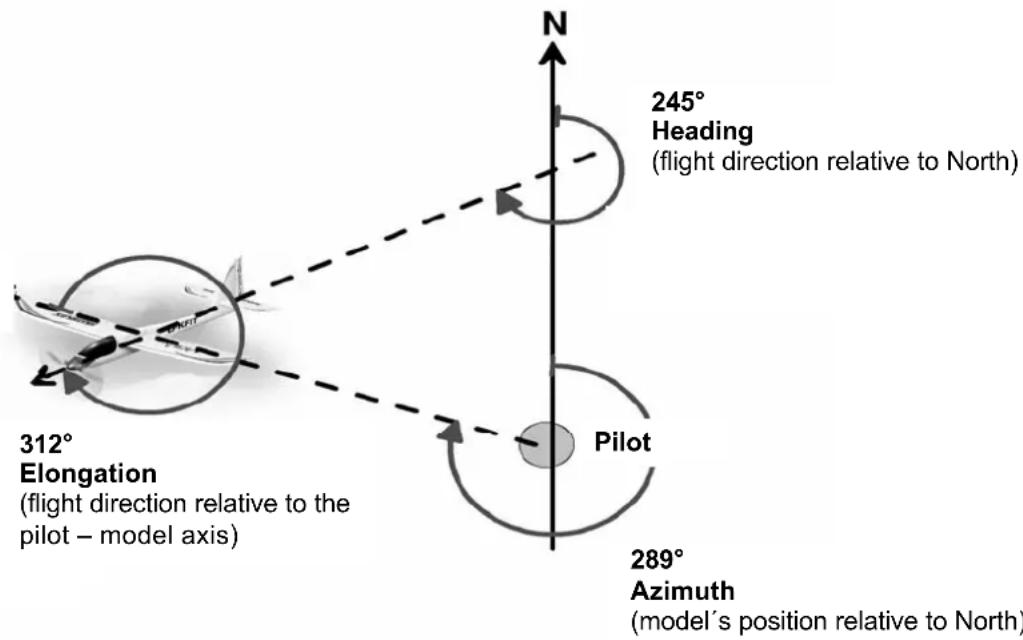
5. Re. the "Azimuth" setting
This angle value represents the model's position relative to North ( 19) . This angular value may well help you to find the model after an out-landing.
6. Re. the "Heading" setting
This angle value represents the "compass in the model": imagine you are sitting in the model and looking at a compass. This angular information enables you to "fly a course" ( 19) .
Examples:
0^ model flying North
90° → model flying East
180° → model flying South
270^ model flying West
7. Re. the "Elongation" setting
This angle value represents the model's direction of flight relative to the pilot. The North Pole plays no role in the "Elongation" setting; what matters is the fixed point ( 19.)!
Examples:
0^ model flying away from the pilot
- 90^ model flying to the right
180° → model flying towards the pilot
270^ model flying to the left
16. CE CONFORMITY DECLARATION
This device has been assessed and approved in accordance with European harmonised directives.

This means that you possess a product whose design and construction fulfil the protective aims of the European Community designed to ensure the safe operation of equipment.
The detailed CE conformity declaration can be downloaded in the form of a PDF file from the Internet under wwwultiplex-rc.de. It is located in the DOWNLOADS area under PRODUKT-INFOS.
17. DISPOSAL NOTES
Electrical equipment marked with the cancelled waste bin symbol must not be discarded in the standard household waste; instead it should be taken to a suitable specialist disposal system.
In the countries of the EU (European Union)
electrical equipment must not be discarded via the normal domestic refuse system (WEEE - Waste of Electrical and Electronic Equipment, Directive 2002/96/EG). You can take unwanted equipment to your nearest local authority waste collection point or recycling centre. There the equipment will be disposed of correctly and at no cost to you.
By returning your unwanted equipment you can make an important contribution to the protection of the environment!
18. GUARANTEE / LIABILITY EXCLUSION
The company MULTIPLEX Modellsport GmbH & Co.KG accepts no liability of any kind for loss, damage or costs which are due to the incorrect use and operation of this product, or which are connected with such operation in any way. Unless the law expressly states otherwise, the liability on the part of MULTIPLEX Modellsport GmbH & Co.KG to pay damages, regardless of the legal argument employed, is limited to the invoice value of those products supplied by MULTIPLEX Modellsport GmbH & Co.KG which

were directly involved in the event in which the damage occurred. This does not apply if liability is incurred according to statutory law on account of intentional or gross negligence.
We guarantee our products in accordance with the currently valid statutory regulations. If you wish to make a claim under guarantee, your initial course of action should always be to contact the dealer from whom you purchased the equipment.
The guarantee does not cover faults and malfunctions which are caused by the following:
Incorrect or incompetent use
- Maintenance carried out incorrectly, belatedly or not at all, or not carried out by an authorised Service Centre
Incorrect connections
- The use of accessories other than genuine MULTIPLEX items
- Modifications or repairs which were not carried out by MULTIPLEX or by an authorised MULTIPLEX Service Centre
- Accidental or intentional damage
- Defects due to normal wear and tear
Operation of the unit outside the limits stated in the Specification
Operation of the unit in conjunction with equipment made by other manufacturers.
19. AZIMUTH, HEADING, ELONGATION
Elongation / Elongation
Elongation / Elongation
Elongation / Elongation
Elongation / Elongation
Elongation / Elongation
Elongation / Elongation