RX7DR - Remote control toy MULTIPLEX - Free user manual and instructions
Find the device manual for free RX7DR MULTIPLEX in PDF.

| Product type | 2.4 GHz radio control receiver |
| Brand | Multiplex |
| Model | RX7DR |
| Dimensions | approx. 49.0 x 34.0 x 11.5 mm |
| Weight | 19 g |
| Supply voltage | 3.5 V to 9.0 V (4-6 cells NiXX or 2S LiPo/LiIo) |
| Number of channels | 7 |
| Current consumption | approx. 60 mA (without servos) |
| Transmission technology | M-LINK FHSS 2.4 GHz |
| Signal resolution | 12 bit, 3872 steps |
| Pulse duration (Fast Response) | 14 ms |
| Pulse duration (Standard) | 21 ms |
| Main functions | Dual-Receiver (diversity), integrated telemetry, error counter, HOLD/FAIL-SAFE, PC interface, firmware update |
| Antenna length | approx. 20 cm (2x, active part 3 cm) |
| Operating temperature | -20°C to +55°C |
| Transmitter compatibility | All Multiplex M-LINK transmitters (e.g. ROYALpro, COCKPIT SX M-LINK) |
| Maintenance and cleaning | Protect from vibration and moisture; clean with a dry cloth |
| Safety | Perform regular range checks; follow assembly and power supply instructions |
| Spare parts and repairability | Antennas replaceable by a professional; Diversity cable (# 8 5070) available |
| General information | Warranty according to legal conditions; CE declaration of conformity available online |
Frequently Asked Questions - RX7DR MULTIPLEX
User questions about RX7DR MULTIPLEX
0 question about this device. Answer the ones you know or ask your own.
Ask a new question about this device
Download the instructions for your Remote control toy in PDF format for free! Find your manual RX7DR - MULTIPLEX and take your electronic device back in hand. On this page are published all the documents necessary for the use of your device. RX7DR by MULTIPLEX.
USER MANUAL RX7DR MULTIPLEX
These operating instructions are an integral part of the product, and contain important information and safety notes. Please store them in a safe place, where you can find them at any time, and pass them on to the new owner if you sell the receiver.
- SPECIFICATION
| RX-7-DR M-LINK RX | -9-DR M-LINK | |
| Order No. # 5 5811 | # 5 5812 | |
| Reception system | 2.4 GHz FHSS M-LINK Frequency Hopping Spread Spectrum MULTIPLEX-LINK | |
| Servo channel count | 7 | 9 |
| Servo frame rate | Fast Response: 14 ms Standard: 21 ms | |
| Signal resolution 12-bit, 3872 steps | ||
| Current drain Approx. | 60 mA (excl. servos) | |
| Aerial length | Total: approx. 20 cm (2 x), of which feed cable approx. 17 cm and active aerial section approx. 3 cm | |
| Operating voltage | 3.5 V ... 9.0 V → 4 - 6 NiCd / NiMH (NiXX) cells → 2S LiPo / Lilo | |
| Operating temperature range | - 20°C ... + 55°C | |
| Weight 19 g | ||
| Dimensions | Approx. 49.0 x 34.0 x 11.5 mm | |
2. SPECIAL FEATURES
- High-quality 7-channel / 9-channel receivers assembled using the latest SMT methods, exploiting MULTIPLEX 2.4 GHz M-LINK technology, suitable for all types of model.
Dual receivers:
Each receiver features two complete reception circuits working in parallel (receiver diversity). This ensures excellent reception quality by minimising directional effects.
Supplementary signal pre-amplification: For highest possible sensitivity.
In-line connector arrangement: Ideal for models with limited internal space.
HOLD/FAIL-SAFE function.
- Integral SET button and LED:
For binding, FAIL-SAFE programming, RESET and displaying operating status information.
- Telemetry / feedback channel capability: Receiver battery voltage and connection quality = standard features. Integral sensor interface for connecting external sensor modules.
- Prepared for two-receiver operation: Diversity lead (# 85070) required.
- Integral error counter / data logger: For voltage and signal errors.
- Compatible with the MULTImate (# 8 2094).
- Integral PC interface:
- Carry out updates and change settings using the RX DataManager PC program.
3. SAFETY NOTES
Please read the instructions before using the receiver.
Use the receiver only for the intended applications ( 4.)
Ensure the power supply is of adequate capacity ( 6) .
Observe the installation notes ( 18)
Carry out regular range checks ( 13) .
4. APPLICATIONS
The RX-7-DR M-LINK and RX-9-DR M-LINK 2.4 GHz receivers (abbreviated to RX-7/9-DR M-LINK in this document) are radio control receivers intended exclusively for use in model sport. It is prohibited to employ them for other purposes such as full-size (people-carrying) vehicles or industrial installations.
5. COMPATIBILITY
RX-7/9-DR M-LINK 2.4 GHz receivers can only be operated in conjunction with transmitters which utilise MULTIPLEX M-LINK transmission technology.
These are as follows (correct as of February 2010):
ROYALpro 7,9 and 16 M-LINK.
- ROYALeko or pro 7, 9 and 12 with firmware version V3.xx and the HFM4 M-LINK 2.4 GHz RF module.
PROFImc 3010, 3030 and 4000 with the HFM3 M-LINK 2.4 GHz RF module.
COCKPIT SX M-LINK.
- MULTIPLEX transmitters with the HFMx M-LINK 2.4 GHz RF module.
±b^* Note:
Unless stated otherwise, when this document refers to the transmitter types ROYALeko, ROYALpro, and PROFImc 3010, 3030 and 4000, the terms refer to the 2.4 GHz M-LINK versions.
6. POWER SUPPLY
RX-7/9-DR M-LINK receivers work within a broad range of voltages from 3.5V ... 9.0 V, i.e. they can be used with receiver batteries consisting of four to six NiXX cells or 2S LiPo / 2S Lilo.
Note: if you intend to use a five-cell or six-cell NiXX battery, or a 2S LiPo or 2S Lilo pack, it is essential to check that all the servos, gyros and other components connected to the system are approved for use with this higher operating voltage.
Note: ensure that the power supply is adequate
A power supply system in good condition and of adequate capacity for the specific application plays an indispensable role in the safe operation of any model:
- Use only high-quality receiver batteries of adequate capacity. Balance and maintain them carefully, and charge them fully.
- Ensure that all cables are of adequate conductor cross-section. Keep all wiring as short as possible, and use the absolute minimum of plug / socket connections.
- Use high-quality switch harnesses exclusively.
- Brief collapses in the power supply voltage (lasting a few milli-seconds) have no adverse effect on the receiver. Longer voltage collapses to below 3.5V may cause a receiver reset, resulting in a brief interruption in reception. This may be due to a receiver battery which is almost flat, too weak or defective, cables of inadequate cross-section, poor-quality connectors or an overloaded or defective BEC system.
7. RECEIVER CONNECTIONS
This receiver employs the UNI connector system, which is compatible with the connector systems used by most radio control manufacturers (e.g. HiTEC, robbe/Futaba, Graupner/JR).
The receiver sockets are marked as follows:
| 1, 2, 3 ... 7 (... 9) | Servo sockets, channels 1, 2, 3 ... 7 (... 9). Alternatively: receiver battery socket. |
| B | In the case of the RX-7-DR M-LINK: Receiver battery socket (can also be connected to servo sockets 1 ... 7). Duplicated for extra security: twice the conductor cross-section, twice the number of contacts. |
| B/D | Receiver battery socket (can also be connected to servo sockets 1 ... 7 (... 9)). Duplicated for extra security: twice the conductor cross-section, twice the number of contacts. Socket for PC or Diversity cable / MULTIMATE. |
| SENSOR Socket for external sensor module. | |
When connecting the receiver battery, servos, speed controllers, sensors ... it is essential to insert the connector the correct way round. With other makes of component always check the pin assignment (see symbols on the receiver)!
8. FIRST USE, FUNCTIONS
8.1 LED Codes
| LED code Description | |
| LED Code 0 LED OFF | Battery voltage too low |
| LED Code 1 LED ON | No reception |
| LED Code 2 1,6 sec | Binding procedure in progress |
| LED Code 3 1,6 sec | Normal receiving operation, no errors |
| LED Code 5 1,6 sec | Confirmation signal |
| LED Code 6 1,6 sec | 1 - 19 errors |
| LED Code 7 1,6 sec | 20 - 49 errors |
| LED Code 8 1,6 sec | >= 50 errors |
8.2 The functions of the SET button
Pressing the SET button on the top of the receiver when switching on initiates the binding process (3.3).
In receive mode, the SET button can be used to trigger two additional functions. The function selected depends on the length of the button-press:
- Save error counter or FAIL-SAFE settings
Press the SET button for 0.5 to 1 second (→ 8.8 and → 8.5).
- RESET receiver to factory default settings
Press the SET button for longer than ten seconds (→ 8.6).
While the SET button is pressed, the LED indicates the length of the button-press with time markers:
| Press SET button constantly for | < 2 seconds | 2 to 10 seconds | > 10 seconds |
| LED OFF | ON | OFF | |
| Purpose Save | error counter / FAIL-SAFE settings | RESET to default settings |
Note:
When the Save process is complete, the LED flashes in confirmation (LED code 5 8.1 ).
8.3 Binding
The receiver must be set up to match the transmitter before the system can work. This process is known as "binding".
Note:
The signal output to the servo sockets is switched off during the binding procedure. This means that the servos are "soft", and do not move, while the motor connected to a modern electronic speed controller remains OFF due to the lack of a signal. Nevertheless, it is important to secure the model and keep well clear of the power system.
The binding process is necessary in the following cases:
The first time the receiver is used ( 8.3.1)
After a receiver RESET ( 8.6)
- After the transmitter setting for "Fast Response" has been changed. For more information on this please refer to the operating instructions supplied with your M-LINK transmitter or M-LINK RF module.
After the transmitter setting for the transmitted frequency range has been changed. For more information on this please refer to the operating instructions supplied with your transmitter or M-LINK RF module ("France mode").
- If the receiver is to be operated in conjunction with a different M-LINK transmitter.
8.3.1 Sequence of the binding procedure
-
The first step is always to set the transmitter and receiver to Binding mode:
-
Place the transmitter and the receiver aerials close together.
- Switch the transmitter ON in binding mode. (see the operating instructions supplied with your M-LINK transmitter or M-LINK RF module).
- Switch the RX-7/9-DR M-LINK receiver ON in binding mode:
-
Use a pointed object to press and hold the SET button on the top of the receiver ( 8.2) .
-
Switch the receiver ON, or connect the battery:
The binding procedure runs, the receiver LED flashes at high frequency (LED code 2 8.1).
Now release the SET button.
Note: the binding process starts automatically when the receiver is used for the first time, and after a RESET - even if you have not pressed the SET button.
- Once the transmitter and receiver are bound to each other, both switch automatically to normal operation ( 8.4) :
The LED on the receiver flashes slowly (LED code 3 8.1 ).
Note: in most cases the binding process only takes a few seconds.
8.3.2 Binding: locating and correcting faults
Fault:
During the binding process the receiver LED continues to flash at a high rate after several seconds.
Cause:
No M-LINK signal of adequate strength detected.
Remedy:
- Reduce the distance between your transmitter and the receiver aerials.
- Ensure that your transmitter is switched ON in binding mode.
- Repeat the binding procedure.
8.4 Switching the receiver ON and OFF in normal operations
8.4.1 Sequence of switching ON and OFF
To switch the M-LINK RC system ON, please use this procedure:
- Switch the transmitter ON.
- Switch the receiver ON.
The receiver LED flashes slowly and evenly
(LED code 3 → 8.1):
An M-LINK signal is being received, the RC system is ready for use.
To switch the M-LINK RC system OFF, please use this procedure:
- Switch the receiver OFF.
- Now switch the transmitter OFF.
8.4.2 Locating and correcting faults when switching ON Fault:
The receiver LED lights up constantly when switched on (LED code 1 8.1 ), but does not flash.
Cause:
No M-LINK signal detected.
Remedy:
Is the transmitter switched on?
- Is the transmitter generating an M-LINK signal?
- Are the transmitter and receiver bound to each other?
- Have you carried out a receiver RESET ( 8.2 , 8.6 )?
- Have you made changes to the setting for "Fast Response" ( 8.3) or "France mode" ( 8.3) ?
Error:
The receiver LED stays off after switching on (LED code 0 8.1 ).
Cause:
The operating voltage (battery voltage) is too low.
Remedy:
- Recharge the receiver battery or drive / flight battery.
8.5 HOLD and FAIL-SAFE
If no signal is picked up, or if the received data is corrupt, the last valid information is passed on to the servos in order to bridge the signal loss (HOLD mode).
If interference should occur and FAIL-SAFE has been invoked, the servos (...) run to a previously defined position at the end of the HOLD period. FAIL-SAFE mode ends as soon as error-free signals are picked up again.
The factory default setting for the HOLD period is 0.75 seconds. This period can be adjusted to meet personal requirements using the MULTImate ( 11.) or the PC program RX DataManager ( 11.)
FAIL-SAFE is switched OFF in the receiver's default state (as delivered), and after a RESET. FAIL-SAFE is activated using the SET button on the receiver, or - in the case of certain transmitters - "by radio".
If you wish to disable FAIL-SAFE again, the receiver must be reset to the default state (RESET 8.6). After a RESET you must repeat the binding procedure ( 8.3)!
Note: always activate FAIL-SAFE!
For safety reasons we recommend that you always activate FAIL-SAFE, and ensure that the selected FAIL-SAFE settings will cause the model to take up as safe an attitude as possible (e.g. motor idle / electric motor OFF, control surfaces neutral, landing flaps deployed, tow-release open, ...).
Selecting the FAIL-SAFE settings:
- The receiver LED must not display any errors (LED code 3 8.1
If it does: switch the receiver OFF, then ON again.
- Use your transmitter to move all the servos (and the speed controller) to your preferred FAIL-SAFE positions. Press the SET button briefly (0.5 to 1 second). The FAIL-SAFE positions are now stored for all servo channels, and the LED flashes the confirmation signal (LED code 5 8.1 ).
Testing the FAIL-SAFE positions:
Move the sticks to positions other than the FAIL-SAFE settings, and then switch the transmitter OFF: the servos should go into HOLD mode briefly (0.75 seconds), and then move to the FAIL-SAFE positions which you previously selected.
The FAIL-SAFE positions must always be checked and updated when necessary, e.g. when you install the receiver in a new model.
Checking the FAIL-SAFE function:
For testing the FAIL-SAFE function only, the receiver can be operated with the transmitter switched off. Caution: if the FAIL-SAFE settings are incorrect, the motor could burst into life: injury hazard!
After sixteen seconds in FAIL-SAFE the receiver ceases to send control signals to the servos (default setting; this period can be changed using the MULTImate or RX DataManager ( 11)
Analogue servos and some digital servos (see instructions) then become "soft", to avoid them being stalled. Modern speed controllers switch themselves off. However, some digital servos remain "hard" and maintain their last position.
The MULTImate or RX DataManager can be used to activate or disable the FAIL-SAFE function servo by servo. Example: throttle only to Idle / OFF, all other servos = HOLD.
8.6 RESET to factory default settings
The receiver settings can be reset to the factory default settings. If you do this, all the settings you have entered, such as binding information, FAIL-SAFE settings ... are lost permanently.
Hold the SET button pressed in for at least ten seconds (as a guide, the LED goes out when you press the button, comes on again after two seconds, then off again after ten seconds).
When the RESET has been carried out, the LED displays the confirmation signal (LED code 5 8.1 ), and the receiver switches to binding mode.
Note: it is not possible to carry out a RESET if the receiver is in binding mode (LED flashing at high frequency).
8.7 Overview of the factory default settings and variable set-up values
| Parameter Default setting Set-up value | ||
| variable using MULTImate*and RX DataManager* | ||
| Low voltage (error counter) | 4.5 V Yes | |
| HOLD period 0.75 seconds | Yes | |
| FAIL-SAFE period 16 seconds | Yes | |
| FAIL-SAFE Off Can be activated | channel by channel | |
| Receiver name Internal ID Max. 12 characters | ||
| Address for receiver battery voltage | 0 | Yes |
| Address for connection quality | 1 | Yes |
*Refer to Chapter (→ 11.) here.
8.8 Error counter
The receiver features two error counters: for low voltage and signal errors.
The receiver LED indicates the sum of the seconds during which errors were detected.
If errors are indicated, they can be saved (stored) after the landing using the SET button ( 8.2) , and read out again later ( 11.)
1. Operating voltage errors
Examples: flat or faulty battery, inadequate cable cross-section, etc.
The error count contains all voltage collapses below the threshold of 4.5V (value can be changed using the MULTI- mate or RX DataManager 11 -
2. Signal errors
The count contains instances of interference to the M-LINK signal packet. For example, this could indicate problems in the power supply, a defective aerial, etc.
Signal errors are recorded in virtually every flight. In most cases the pilot does not notice them, but they are still picked up by the extremely sensitive error counter.
After a few flights, and regular analysis of the error counter, you will gain the experience required to render the error counter genuinely helpful, enabling you to detect changes in good time, and to locate indications of possible causes of interference.
Protracted voltage collapses below 3.5V cause the receiver to re-boot. If this occurs, the values for both error counters are lost permanently.
If you press the SET button for the purpose of saving the error count, the stored information is retained until the next time you save the error count.
9. TELEMETRY / FEEDBACK CAPABILITY
The telemetry-capable RX-7-DR M-LINK and RX-9-DR M-LINK 2.4 GHz receivers offer a means of transmitting data from the model back to the transmitter.
When these receivers are employed, the telemetric values for "receiver battery voltage" and "connection quality" are transmitted directly, i.e. they require no additional external sensors.
The receivers can also be used in conjunction with up to sixteen external M-LINK sensors, which are connected to the SENSOR socket. In this way a very wide variety of telemetry data can be "sent back" to the pilot.
Note:
The possible methods of indicating telemetry data by visual and / or audible means vary according to the M-LINK transmitter or RF module in use.
Examples of external M-LINK sensors are as follows:
Voltage sensor (# 85400).
- Temperature sensor (# 85402).
Current sensor. Max. 100 A (# 85401) or max. 35 / 60 A (# 85403).
Rev count sensor: Optical (# 8 5414) or magnetic (# 8 5415).
- Vario / altitude sensor (# 85416).
For more information on connecting and operating the various sensor types and their features (measurement range, addressing, warning threshold settings, display facilities for minimum, average or maximum values, in some cases activation of a second measurement channel, ...) please refer to the instructions supplied with the sensors and / or the MULTImate.
10. TWO-RECEIVER MODE
MULTIPLEX RX-7/9-DR M-LINK receivers are what are known as "dual receivers", ("DR"): each receiver case contains two complete receiving circuits operating in parallel ("receiver diversity"). It is also possible to connect two receivers together using the Diversity lead (# 85070). In this configuration a total of four receiving circuits is operating in parallel:
All four receiving circuits installed in the two receiver cases pick up and assess the signals ("quadruple diversity"). In this section we refer to this type of diversity as "two-receiver mode".
Two-receiver mode is possible with various MULTIPLEX M-LINK receivers starting with the RX-7-DR M-LINK. You can also connect different M-LINK receiver types together, provided that both are capable of two-receiver operation (e.g. 1 x RX-16-DR pro M-LINK and 1 x RX-7-DR M-LINK).
The different orientation of all four receiver aerials provides a further improvement in the reception performance, since this arrangement minimises the directional aerial effect. This means that one receiver aerial always has a good "view" of the transmitter regardless of the model's attitude. Two-receiver mode therefore provides an additional safety margin. Two-receiver mode is particularly recommended for use in large-scale model aircraft.
11. MULTIMATE AND RX DATAMANAGER PC PROGRAM
All MULTIPLEX M-LINK receivers are based on modern microcontrollers (FLASH technology). In the case of most M-LINK receiver types (see the operating instructions supplied with your receiver) it is also possible to connect the unit to the MULTImate (# 8 2094) and / or to a PC or notebook computer using the PC connecting lead (# 8 5149); the PC program RX DataManager can then be used.
The PC program RX DataManager is available as a free download from the MULTIPLEX website (www.multiplex-rc.de). This program or MULTIMATE opens up the following possibilities:
- Availability of expanded receiver options, such as freely variable HOLD and FAIL-SAFE period, individual FAIL-SAFE settings can be activated and adjusted channel by channel, ...
- Error counter / error memory read-out The error count can be read out separately for signal errors and operating voltage errors.
- Unrestricted sensor address assignment for the receiver battery voltage and for connection quality (0 - 15).
- Receiver name assignment (max. 12 characters).
The RX DataManager program also allows:
Firmware update.
12. INSTALLATION NOTES
- Protect your receiver from vibration, especially in models powered by an internal-combustion engine (e.g. pack it loosely in foam).
- Locate the receiver at least 150mm away from electric motors, petrol engine ignition systems and any other electronic components such as speed controllers for electric motors and drive batteries. Do not route the aerials close to these components.
- Install the receiver in the model in such a way that both aerials are as far away as possible from electrically conductive materials, and are arranged at an included angle of 90^ . Locate the two aerial ends as far from each other as possible.
- If the model's fuselage contains conductive material (e.g. carbon fibre), the aerials must be installed in such a way that the active part of the aerial (approximately the last 30mm ) is located outside the model.
- Do not deploy the receiver aerials inside or on model components which are laminated or reinforced with electrically conductive materials (metal foil, carbon fibre, metallic paints etc.), as they have a shielding effect.
- Never shorten or extend the aerials or their feed cables. Never attempt to exchange the aerials yourself!
- Do not deploy the aerials parallel to servo leads, high-current cables or electrically conductive parts (e.g. pushrods).
- Keep to the recommended installed arrangements ( 18. sketches A-D)!
- High-current cables, e.g. those attached to the speed controller, motor and flight battery, should be kept as short as possible.
- If you are using a diode-based battery backer, always install a PeakFilter (# 85180).
- Reception quality can be optimised by fitting a special ferrite ring (# 8 5146) or suppressor filter lead (# 8 5057) in the speed controller cable. It is also advisable to fit effective suppressors
to conventional (brushed) electric motors (not brushless types) (e.g. use the suppressor set # 8 5020).
13. RANGE CHECKING
Regular range checks are very important - even when using a 2.4 GHz system - in order to ensure reliable operation of the radio control system, and to enable you to detect sources of interference in good time. This applies in particular:
- Before the use of new or changed components, or existing components in a new or modified arrangement.
- Before re-using radio control system components which were previously involved in a crash or a hard landing.
- If you have encountered problems on a previous flight.
Important:
- Always ask a second person to help you with your range check, so that one of you can secure and observe the model.
- If possible, carry out the range check when no other transmitters are operating.
Carrying out the range check:
- Select "range-check mode" on your transmitter (see the operating instructions supplied with the transmitter or RF module).
There must be visual contact between the transmitter and receiver aerials (i.e. the model) during the range check.
Keep the transmitter and the model about one metre above ground during the range check.
- When checked with reduced transmitter power, the range of the RX-7/9-DR M-LINK receiver must be 100 metres. You have reached the range limit when the servos start to move jerkily.
If your transmitter features an automatic servo test facility, we recommend that you activate it for one control function (e.g. rudder). This sets up a steady movement of the servo, and enables you to detect the limit of range clearly.
Important:
Carry out the first range check with the motor switched off. Turn the model into all attitudes, and attempt to optimise reception by changing the position of the two aerials.
For the second range check, run the motor at varying speeds and check that the effective range is not significantly reduced. If there is a marked reduction, locate and eliminate the cause of the interference (caused by the motor, the arrangement of the receiving system and power supply, vibration, etc.).
14. EXCHANGING THE AERIALS
The standard aerial feed cables attached to RX-7/9-DR M-LINK receiver types are long enough for most applications.
If you require longer or shorter aerial feed cables, please contact the MULTIPLEX Service Department or any MULTIPLEX Service Centre, as they stock cables of different lengths, and will gladly quote an individual price for modifying your receiver to professional standards.
Caution: never attempt to exchange the aerials yourself! Changing the aerials to a professional standard requires special tools as well as appropriate expertise. Ignoring this warning may have an adverse effect on the receiver's reception quality.
Caution: if the active part of the aerial (the final 30mm ) should be damaged, the aerial must be replaced by the MULTIPLEX Service Department or a MULTIPLEX Service Centre; the same applies to damaged aerial feed cables.
15. CE CONFORMITY DECLARATION
This device has been assessed and approved in accordance with European harmonised directives.

This means that you possess a product whose design and construction fulfil the protective aims of the European Community designed to ensure the safe operation of equipment.
The detailed CE conformity declaration can be downloaded in the form of a PDF file from the Internet under www.multiplexrc.de. It is located in the DOWNLOADS area under PRODUKTINFOS.
16. DISPOSAL NOTES
Electrical equipment marked with the cancelled waste bin symbol must not be discarded in the standard household waste; instead it should be taken to a suitable specialist disposal system.
In the countries of the EU (European Union) electrical equipment must not be discarded via the normal domestic refuse system (WEEE - Waste of Electrical Electronic Equipment, Directive 2002/96/EG). You can unwanted equipment to your nearest local authority w collection point or recycling centre. There the equipment will disposed of correctly and at no cost to you.
By returning your unwanted equipment you can make an important contribution to the protection of the environment!
17. GUARANTEE / LIABILITY EXCLUSION
The company MULTIPLEX Modellsport GmbH & Co.KG accepts no liability of any kind for loss, damage or costs which are due to the incorrect use and operation of this product, or which are connected with such operation in any way. Unless the law expressly states otherwise, the liability on the part of MULTIPLEX Modellsport GmbH & Co.KG to pay damages, regardless of the legal argument employed, is limited to the invoice value of those products supplied by MULTIPLEX Modellsport GmbH & Co.KG which were directly involved in the event in which the damage occurred. This does not apply if liability is incurred according to statutory law on account of intentional or gross negligence.
We guarantee our products in accordance with the currently valid statutory regulations. If you wish to make a claim under guarantee, your initial course of action should always be to contact the dealer from whom you purchased the equipment.
The guarantee does not cover faults and malfunctions which are caused by the following:
Incorrect or incompetent use
- Maintenance carried out incorrectly, belatedly or not at all, or not carried out by an authorised Service Centre
Incorrect connections
- The use of accessories other than genuine MULTIPLEX items
- Modifications or repairs which were not carried out by MULTIPLEX or by an authorised MULTIPLEX Service Centre
- Accidental or intentional damage
Defects due to normal wear and tear
Operation of the unit outside the limits stated in the Specification
Operation of the unit in conjunction with equipment made by other manufacturers.
18. RECOMMENDED INSTALLATIONS
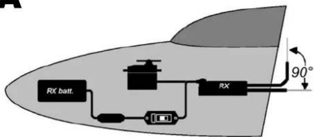
A
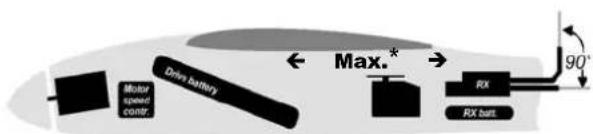
B
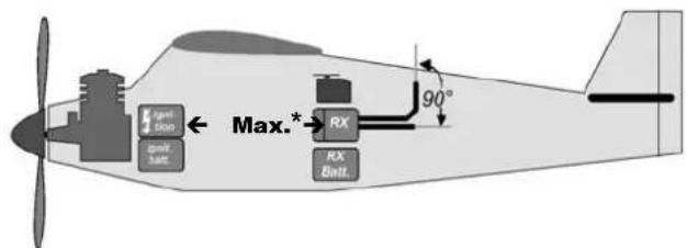
C
D
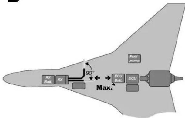
*Max. = As far as possible