MULTIswitch FLEXX - Remote control toy MULTIPLEX - Free user manual and instructions
Find the device manual for free MULTIswitch FLEXX MULTIPLEX in PDF.

| Product type | Switching module for model making (radio-controlled toy) |
| Brand | MULTIPLEX |
| Model | MULTIswitch FLEXX |
| Reference | 75888 |
| Supply voltage | 3.8 to 12 V (3S LiPo battery) |
| Max. total continuous current | 9 A |
| Max. continuous current per channel | 3 A |
| Number of switching channels | 3 |
| Communication protocol | SRXL (MULTIPLEX) |
| Main functions | Light control, DC motors, sound signal, foghorn, light signal; flashing and flash functions |
| Compatible load types | Diodes, incandescent lamps, motors, signal devices |
| Connections | SRXL input/operating voltage, SRXL output, U_BAT terminal, U_BAT jumper, switching channels 1 to 3 |
| LED indicator | Data reception LED (lights up upon correct data reception) |
| PC configuration | Free MULTIPLEX Launcher software (Windows) with USB adapter (ref. 85149) |
| Compatible receivers | All MULTIPLEX telemetry receivers compatible with SRXL, e.g. RX4/9 FLEXX M-LINK ID, RX4/16 FLEXX M-LINK ID |
| Optional accessories | USB adapter for PC (ref. 85149), MULTImate (ref. 82094) |
| Safety instructions | Avoid short circuits, polarity reversal, incorrect voltage; observe max. voltage of 12 V and max. current per channel |
| Maintenance | Check connections, avoid moisture and shocks |
| Warranty | In accordance with legal provisions; not covered: improper use, modifications, normal wear |
| Compliance | European Directive 2002/96/EC (WEEE), CE declaration available as PDF |
Frequently Asked Questions - MULTIswitch FLEXX MULTIPLEX
User questions about MULTIswitch FLEXX MULTIPLEX
0 question about this device. Answer the ones you know or ask your own.
Ask a new question about this device
Download the instructions for your Remote control toy in PDF format for free! Find your manual MULTIswitch FLEXX - MULTIPLEX and take your electronic device back in hand. On this page are published all the documents necessary for the use of your device. MULTIswitch FLEXX by MULTIPLEX.
USER MANUAL MULTIswitch FLEXX MULTIPLEX
These operating instructions are an integral part of this product. They contain important information and safety instructions. They must therefore be kept ready to hand at all times and passed on to third parties when this product is sold.
The MULTIswitch FLEXX works with the serial servo signal MULTIPLEX SRXL. It can therefore be operated by all SRXL-compatible remote control receivers. These include:
- All telemetry-compatible receivers
• RX4/9 FLEXX M-LINK ID
• RX4/16 FLEXX M-LINK ID
1 INTRODUCTION
Thank you for choosing to purchase MULTIswitch FLEXX.
MULTIswitch FLEXX is a universal switching module for model cars, boats and planes. It provides three switching channels, which can be used for the following functions:
- Controlling lighting, DC motors, horn, foghorn, headlight flasher, etc.
- Blink mode for direction indicators / hazard lights
- Flash mode for warning lights, position lights, etc.
2 SAFETY INSTRUCTIONS
! Damage due to short circuits: Do not short terminals 1 to 3 of the switching channels.
! Damage due to reverse polarity: Make sure that the polarity is correct when connecting a voltage to the terminal U(Bat).
! Damage due to incorrect voltage: Make sure that all connected remote control components are designed for the voltage applied at the termina U(Bat). Remove the jumper U(Bat), if necessary.
3 FUNCTIONAL DESCRIPTION
The MULTIswitch FLEXX works with the serial servo signal MULTIPLEX SRXL. The control information is transmitted via a single cable from the remote control receiver to the switching module. This reduces the amount of cabling required in the model.
Because the MULTIswitch FLEXX is controlled by means of SRLX, it can be combined with other function modules or other function modules added.
The MULTIswitch FLEXX can be configured with a Windows PC so that the three switching channels can be used flexibly and independently for different purposes.
4 SPECIFICATIONS
| Order no. | # 75888 |
| Supply voltage | 3.8 – 12 volts(3S LiPo battery) |
| Maximum continuous current load | 9 amps(3 amps per channel) |
5 CONNECTIONS
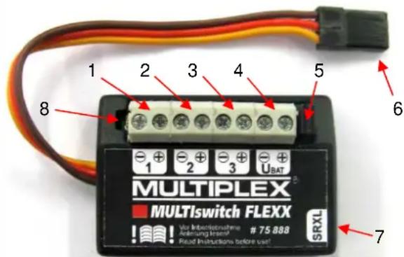
text_image
MULTIPLEX MULTIswitch FLEXX 1 2 3 4 5 6 -1 -2 -3 -4 UBAT MUS VAR INBIOPROUHENE Anleihung insens! Read Instructions before use! 7 SRXLFigure 1 MULTIswitch FLEXX
1 Switching channel 1
2 Switching channel 2
3 Switching channel 3
4 U(Bat); Terminal for supply voltage
5 Jumper U(Bat)
6 SRXL / Operating voltage (from remote control receiver)
7 SRXL output (to other switching module or other SRXL-compatible devices)
8 LED display for receiving data
5.1 Switching channel 1 to 3
Connect the electrical loads here, e.g. LEDs, light bulbs, motors, horn, etc.
Make sure the polarity is correct when connecting the loads (e.g. LEDs).
! Damage due to excessive current load: Make sure that the maximum current load per switching channel is 3 amps.
5.2 SRXL / Operating voltage
Connect the cable to the receiver output at which the serial servo signal MULTIPLEX SRLX is output.
This cable also supplies the MULTIswitch FLEXX with its operating voltage.
5.3 SRXL output
The pin header is connected 1:1 to the SRXL input.
You can connect other SRXL-compatible devices. For example, you can create a chain with several MULTIswitch FLEXX or connect an SRXL-compatible stabilisation system.
5.4 LED display
The LED will light up as soon as the MULTIswitch FLEXX receives the correct data from a remote control receiver or a PC.
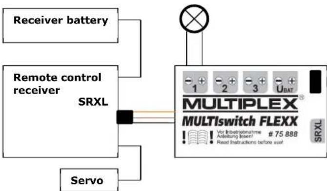
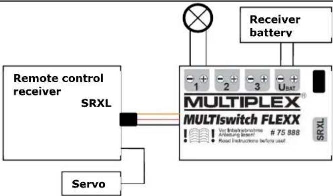
5.5 Jumper U(Bat) / U(Bat) Jumper U(Bat) connected
When the jumper is connected, the operating voltages of the MULTIswitch FLEX electronics, the remote control system and the loads are connected with each other.
In this case, a single voltage source is sufficient to supply the power. This may be a receiver battery that is connected to the remote control receiver.
Alternatively, you can use any voltage source that is connected to the terminal U(Bat).
! Damage due to excessive voltage: Make sure that the voltage does not exceed 12 volts (3S LiPo battery). When the jumper U(Bat) is connected, the maximum operating voltage for ALL connected components (loads, receiver, servos) must not be exceeded. This is usually a maximum of 6 volts for standard servos.
flowchart
graph TD
    A["Receiver battery"] --> B["Remote control receiver SRXL"]
    C["Servo"] --> B
    B --> D["MULTIPLEX MULTI switch FLEXX"]
    D --> E["SRXL"]
    style D fill:#f9f,stroke:#333
Figure 2 Example of jumper U(Bat) connected
flowchart
graph TD
    A["Remote control receiver"] --> B["SRXL"]
    C["Servo"] --> B
    B --> D["MULTIPLEX® MULTISwitch FLEXX"]
    D --> E["Receiver battery"]
    D --> F["SRXL"]
    G["Switch"] --> H["+ 1 -2 -3 + UBAT"]
    D --> I["+ 75 888 / Var Inbetriebnahme Anleitung (Insert) Read Instructions before user"]
Figure 3 Example of jumper U(Bat) connected (alternative)
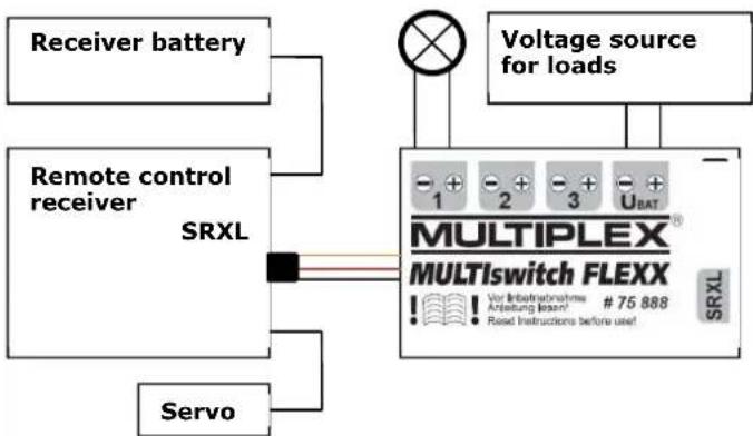
5.6 Jumper U(Bat) / U(Bat) Jumper U(Bat) disconnected
When the jumper is disconnected, the loads can be supplied separately via the terminal U(Bat).
In this case, the MULTIswitch FLEXX electronics and the receiver require their own power supply, e.g. a receiver battery.
! Damage due to excessive voltage: Make sure that the voltage for the loads does not exceed 12 volts (3S LiPo battery). The permissible voltage range of the individual loads must not be exceeded.
flowchart
graph TD
    A["Receiver battery"] --> B["Remote control receiver SRXL"]
    C["Servo"] --> B
    B --> D["Voltage source for loads"]
    D --> E["MULTIPLEX® MULTISwitch FLEXX"]
    E --> F["SRXL"]
    style E fill:#f9f,stroke:#333
    note right of E: V or Infrastrations, Anleaving lease! # 75 888; Read instructions before use!
    end
Figure 4 Example of jumper U(Bat) disconnected
6 SETTINGS
6.1 Settings for SMART SX FLEXX remote control
The factory settings of the MULTIswitch FLEXX are selected so that the three switching channels can be operated using the SMART SX FLEXX transmitter.
| Switching channel | Actuator in the SMART SX FLEXX transmitter | Function |
| 1 Left vertical rocker switch | on / off | |
| 2 Right vertical rocker switch | on / off | |
| 3 Left stick button Press button | to switch on / off | |
6.2 Assignment of free servo channels
If you are using a remote control with freely assignable servo channels, you can control the MULTIswitch FLEXX with the factory settings as follows:
| Servo channel | MULTIswitch FLEXX switching channel |
| 5 1 | |
| 6 2 | |
| 7 3 |
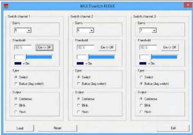
6.3 Settings using MULTIPLEX Launcher
You can customize MULTIswitch FLEXX according to your requirements using the free MULTIPLEX Launcher PC software.
The MULTIPLEX Launcher PC software is available at http://www.multiplexrc.de.
You need the following accessories to connect to a PC:
• MULTIPLEX PC USB adapter #85149
You can specify the following settings for each switching channel:
- Servo channel
- Switching threshold and direction
• Type of switching function - Load control: Duration, blink mode, flash mode
text_image
MULTIswitch FLEXX Switch channel 1 Save 5 Threshold 50 % On > Off - On Type Switch Button (log switch) Output Continuous Blink Flash Switch channel 2 Save 6 Threshold 50 % On > Off - On Type Switch Button (log switch) Output Continuous Blink Flash Switch channel 3 Save 7 Threshold 50 % On > Off - On Type Switch Button (log switch) Output Continuous Blink Flash Send Reset ExitFigure 5 Windows software MULTIPLEX Launcher
7 ERRORS AND SOLUTIONS:
Problem:
MULTIswitch FLEXX is not receiving any data via the SRXL cable (the LED remains off).
Possible causes and solutions:
- MULTISwitch FLEXX must be restarted (e.g. after operation on the PC): Disconnect the supply voltage and reconnect it.
- If you are using a MULTIPLEX telemetry receiver, the SRXL output must be activated first on the receiver (e.g. using the MULTIPLEX PC USB adapter #85149 and MULTIPLEX Launcher or using #82094 MULTImate).
Problem:
The LED for receiving data lights up, but no power is being supplied to the loads.
Possible causes and solutions:
- Jumper U(Bat) is disconnected.
- No voltage source is connected to the terminal U(Bat).
- The servo assignment on the remote control transmitter does not match the settings in the MULTIswitch FLEX.
8 ACCESSORIES
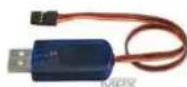
MULTIPLEX PC USB adapter
85149
9 EC DECLARATION OF CONFORMITY

This device has been assessed in accordance with the relevant harmonised European directives.
You are therefore the owner of a product whose design fulfils the protective aims of the European Community relating to the safe operation of the equipment.
The detailed EC declaration of conformity is available as a PDF file online at www.multiplex-rc.de under PRODUCT INFORMATION in the DOWNLOADS area.
10 DISPOSAL
Electrical equipment marked with the crossed out wheeled bin symbol must not be disposed of in the standard household waste, but must instead be taken to a suitable disposal system.
In the countries of the EU (European Union), electrical equipment must not be disposed of via the household or residual waste system (WEEE - Waste of Electrical and Electronic Equipment, directive 2002/96/EC). You can take unwanted equipment to your nearest local authority waste collection point or recycling centre free of charge. There, your equipment will be disposed of correctly and at no cost to you.
By returning your unwanted equipment you can make an important contribution to protecting the environment.
11 GUARANTEE AND LIMITATION OF LIABILITY
MULTIPLEX Modellsport GmbH & Co.KG does not assume any liability for loss, damage or costs which arise through the improper use and operation of our products, or which are connected with such operation in any way. As far as is legally permissible, the obligation of MULTIPLEX Modellsport GmbH & Co.KG to provide compensation for damages, on whatever legal basis, is limited to the invoice amount of the quantity of MULTIPLEX Modellsport GmbH & Co.KG goods that were directly affected by whatever incident gave rise to the damage. This does not apply if MULTIPLEX Modellsport GmbH & Co.KG is obliged to accept unlimited liability in accordance with mandatory law for deliberate or gross negligence.
Our products are covered by the currently valid statutory guarantee regulations. If you wish to make a claim under guarantee, please contact the model shop where you purchased the product.
The guarantee does not cover malfunctions caused by the following:
- Improper operation
- Maintenance that was performed incorrectly, late or not at all, or performed by a non-authorized body
- Incorrect connections
• Use of non-original MULTIPLEX accessories - Modifications / repairs that were not carried out by MULTIPLEX or a MULTIPLEX Service Centre
- Accidental or deliberate damage
• Faults due to normal wear and tear - Operation outside the technical specifications or in connection with components from other manufacturers.
text_image
MULTI switch FLEXX Switch channel 1 Save 5 Threshold 50% On > Off - On Type Switch Button (Jog switch) Output Continuous Blink Flash Switch channel 2 Save 6 Threshold 50% On > Off - On Type Switch Button (Jog switch) Output Continuous Blink Flash Switch channel 3 Save 7 Threshold 50% On > Off - On Type Switch Button (Jog switch) Output Continuous Blink Flash Send Reset ExitFig. 5 - Logiciel Windows MULTIPLEX Launcher
7 ERREURS ET SOLUTIONS
Problème :
text_image
MULTIswitch FLEXX Switch channel 1 Save 5 Threshold 60 % On > Off - On Type Switch Button (Jog switch) Output Continuous Blink Flash Switch channel 2 Save 6 Threshold 60 % On > Off - On Type Switch Button (Jog switch) Output Continuous Blink Flash Switch channel 3 Save 7 Threshold 60 % On > Off - On Type Switch Button (Jog switch) Output Continuous Blink Flash Send Reset ExitFig. 5 Software MULTIPLEX Launcher para Windows
text_image
MULTIswitch FLEXX Switch channel 1 Save 5 Threshold 60% On > Off - On Type Switch Button (Jog switch) Output Continuous Blink Flash Switch channel 2 Save 6 Threshold 60% On > Off - On Type Switch Button (Jog switch) Output Continuous Blink Flash Switch channel 3 Save 7 Threshold 60% On > Off - On Type Switch Button (Jog switch) Output Continuous Blink Flash Send Reset ExitFig. 5 Software Windows MULTIPLEX Launcher