
FUBE50000 - Alarm system ABUS - Free user manual and instructions
Find the device manual for free FUBE50000 ABUS in PDF.
| Product Type | Wireless control element for alarm system |
| Brand | ABUS |
| Model | FUBE50000 |
| Dimensions (L x W x H) | 120 x 120 x 30 mm |
| Weight | Approx. 200 g (with batteries) |
| Power supply | 3 AA alkaline batteries (backup) or 12-15 V DC / 9-12 V AC via external power supply unit |
| Main functions | Activation/deactivation of alarm system, chip key reading, built-in piezo siren, 4 status LEDs for partitions, control of switching outputs, fault indication |
| Display | 4 status LEDs: red (armed), green (disarmed), yellow (internally armed), flashing for transmission and faults |
| Radio frequency | 868.6625 MHz |
| Max transmission power | 10 mW |
| Operating temperature | -10 to +55 °C |
| Humidity | 94% max (non-condensing) |
| Protection rating | IP44 (indoor and protected outdoor) |
| Security grade | 2 |
| Encryption | 16,777,214 variants |
| Certifications | EN50131-3 |
| Access code | 4 or 6 characters |
| Maintenance and cleaning | Clean with a dry, soft cloth. Do not use abrasive products or solvents. |
| Safety | Tamper contact, keyboard lock after 3 incorrect entries (5 min), battery backup power |
| Spare parts and repairability | Commercially available standard AA batteries; for other parts, contact ABUS after-sales service |
| Warranty | 2 years |
| General information | WEEE-compliant disposal; CE declaration of conformity available upon request |
Frequently Asked Questions - FUBE50000 ABUS
User questions about FUBE50000 ABUS
0 question about this device. Answer the ones you know or ask your own.
Ask a new question about this device
Download the instructions for your Alarm system in PDF format for free! Find your manual FUBE50000 - ABUS and take your electronic device back in hand. On this page are published all the documents necessary for the use of your device. FUBE50000 by ABUS.
USER MANUAL FUBE50000 ABUS

Secvest wireless control device

Security Tech Germany
EN Installation instructions and user guide
Contents
Introduction 24
Safety information 25
Scope of delivery 26
Technical data 27
Functional principle and features 28
Installation and start-up 32
Displays and functions.... 34
Warranty 39
Disposal 40
Declaration of conformity 40
Introduction
Introduction
Information on User Guide
Dear customer,
Thank you for purchasing this product. This device is built with state-of-the-art technology.
These instructions contain important installation and operation information. Follow the directions and instructions in this user guide to ensure safe operation. Store this guide in a safe place for future reference. This guide constitutes part of the device. If you pass the device on to third parties, please remember to include this guide with the device.
Intended use
Only use the device for the purpose for which it was built and designed. Any other use is not considered to be the intended use.
Limitation of liability
Everything possible has been done to ensure that the content of these instructions is correct. However, neither the author nor ABUS Security-Center GmbH & Co. KG can be held liable for loss or damage caused by incorrect or improper installation and operation or failure to observe the safety instructions and warnings. No liability can be accepted for resulting damage. No part of the product may be changed or modified in any way. If you do not follow these instructions, your guarantee claim becomes invalid.
We reserve the right to make changes to these instructions without prior notice.
© ABUS Security-Center GmbH & Co. KG, 09 / 2014
Safety information
Explanation of symbols
The following symbols are used in this manual and on the device:
| Symbol | Signal word | Meaning |
 | Caution | Indicates a risk of injury or health hazards. |
 | Caution | Indicates a risk of injury or health hazards caused by electrical voltage. |
 | Important | Indicates possible damage to the device/accessories. |
 | Note | Indicates important information. |
Battery warning information
The device is powered by three 1.5 V alkaline batteries. To guarantee a long service life and avoid fire and injury, please note the following:

- The batteries must not be exposed to heat or direct sunlight, and must not be stored in places with very high temperatures.
Safety information | Scope of delivery

• The batteries must not be burned.
- The batteries must not come into contact with water.
- The batteries must not be dismantled, pierced or otherwise damaged.
- The battery contacts may not be short-circuited.
- The batteries must be kept away from small children.
• The batteries cannot be recharged.
- Do not dispose of the batteries in domestic waste.
Packaging

- Keep packaging material and small parts away from children. There is a risk of suffocation.
- Remove all packaging material before using the device.
Scope of delivery
• Secvest wireless control panel
• Installation instructions and user guide
• 3 AA alkaline batteries
- Installation material
Technical data
| • Dimensions (L x W x H) | 120 x 120 x 30 mm |
| • Displays | 4 status LEDs for partitions |
| • Operating temperature | -10°C to 55°C |
| • Wireless frequency | 868.6625 MHz |
| • Power | max. 10 mW |
| • Humidity | max. 94% (non-condensing) |
| • Degree of protection | IP54 (indoors / protected outdoor areas) |
| • Security level | 2 |
| • Signals | Integrated piezo sounder |
| • Power supply | 3 AA alkaline batteries(optional 9-15 V DC / 9-12 V AC || external PSU) |
| • Nominal power consumption | 100 mA |
| • Environmental class | II |
| • Encryption | 16.777.214 ( 224 – 2) variants |
| • Certifications | EN50131-3 |
| • Access code | 4-digit or 6-digit |
Functional principle and features
Functional principle and features
General
The Secvest wireless control panel (FUBE50000) is an optional accessory module for the Secvest wireless alarm system (FUAA50xxx).
It can arm and disarm either the whole wireless alarm system or partitions therein, and it also has an integrated chip key reader. In order to use this component, the wireless control panel must be externally supplied with 12 V direct current. The wireless control panel can also be used to control switching outputs for the alarm panel.
This device is mainly used on side entrance doors, garage doors and other access areas. Since it features protection class IP44, it can be used both indoors and in protected outdoor areas.
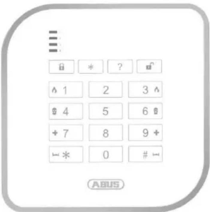
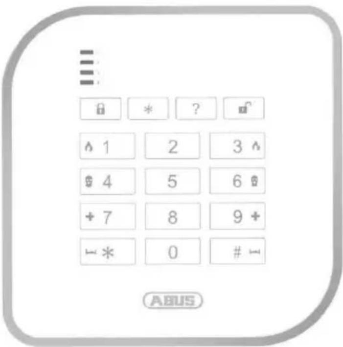
Device description
![graph TD A["Status LEDs (partitions 1 to 4)"] <--> B["Function keys"] B <--> C["Keypad"] C <--> D["Chip key reader"] style A fill:#f9f,stroke:#333 style B fill:#ccf,stroke:#333 style C fill:#cfc,stroke:#333 style D fill:#fcc,stroke:#333](/content/2026/02/391747/images/ed4d43ee39c82e0087d7d4aa0932c0fd40d50e7ec602157be14a651ae8ca5504.jpg)
Functional principle and features
LED status display
The control panel's four status LEDs indicate the statuses of the four partitions. The different statuses are indicated as follows:
RED
→ Activated
RED
-flashing-
→ Transmission to the alarm system
GREEN
→ Deactivated
GREEN
-flashing-
→ Wait for confirmation
(all 4 LEDs simultaneously)
YELLOW
→ Internally armed
YELLOW
-flashing-
→ Interference
(separate for each partition)
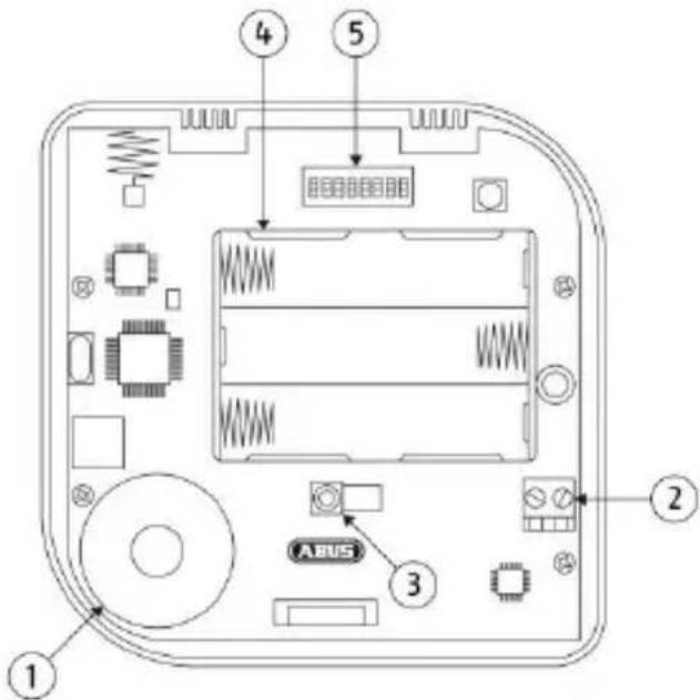
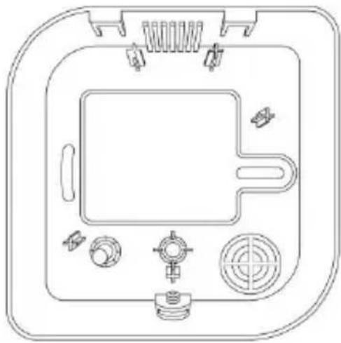
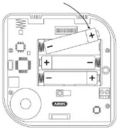
① Piezo sounder
② 12 V connection for power supply unit
③ Tamper contact
④ Battery compartment (3 AA alkaline batteries)
⑤ DIP switches
Functional principle and features
DIP switch layout
| Function | Functions in combination with... | Default setting | ||||
| Battery | Power supply unit | |||||
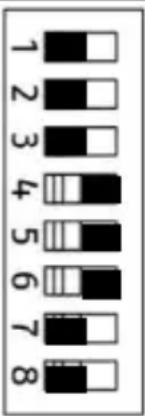 | 1 | Permanent status LEDs | X | Deactivated | ||
| 2 | Backward compatibility→ activated = FU80xx→ deactivated = FUAA50xxx | X | X | Deactivated | ||
| 3 | Battery operationactivate in order to avoid an 'Ext. PSU error' status message when in battery mode (without power supply unit). | X | X | Deactivated | ||
| 4 | Alert tones on control panel | X | Activated | |||
| 5 | Keypad tones | X | X | Activated | ||
| 6 | Chip key reader | X | X | Activated | ||
| 7 | Keypad illumination | X | Deactivated | |||
| 8 | n.a. | Deactivated | ||||
Functional principle and features
Keypad lighting
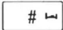
The brightness of the keypad lighting can be adjusted using the following key combination:


Keypad lighting deactivated


Brightness level 1

Brightness level 2
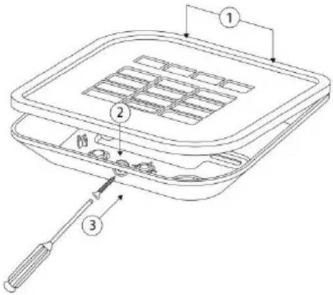
Installation and start-up
Installation and start-up
- Open the wireless control panel housing by removing the screws on the bottom.
- Use the base plate as a drilling template and mark the holes on the wall. Drill the holes and insert the screw anchor.

When marking out the drill holes, make sure there are no electrical wires or cables, pipes or other important components behind them.

- Insert the three AA alkaline batteries in the battery compartment. Make sure the polarity is correct.

Running time in emergency power mode (in the event of a power failure) and/or length of battery life when operating without an external power supply is roughly up to 1 - 2 years.
The actual battery life largely depends on which functionalities are used (proximity chip reader etc.) and the frequency of operations on the control device.
Installation and start-up

- If DIP switch 6 (chip key reader) is activated when the control panel starts up, the status LED for partition 1 will flash green during chip key reader calibration.
- If DIP switch 6 (chip key reader) is deactivated when the control panel starts up, calibration will be performed as soon as the DIP switch is activated.
- Keep the chip key and any other metal objects away from the chip key reader during calibration to avoid disrupting the process.

- If the tamper contact is open when the control panel starts up, the following LED test will be performed:
(1.) All four status LEDs flash red
(2.) The transmitting LED (RF TX) located on the PCB lights up
(3.) The test LED (TEST) lights up
(4.) The SW version of the control panel is indicated by the RF TX LED - If the tamper contact is closed when the control panel starts up, the aforementioned test will not be performed.
Installation and start-up | Displays and functions
-
Screw the back of the housing to the wall.
-
Teach in the wireless control panel (see chapter 'Read-in process') and lock the cover in place.
Displays and functions
Teach-in process
- Set the Secvest to 'teach-in mode' (see installation instructions for wireless alarm system) and send a teach-in signal from the wireless control panel to the wireless alarm system.
- The teach-in signal can be sent either by inserting the batteries or by activating the tamper switch.
- Once the teach-in signal has been picked up by the wireless alarm system, it will emit two beeps and the incoming signal strength will be displayed.
- Confirm the successfully completed teach-in on the control panel.
Displays and functions
Operation

- You can cancel an incorrect code entry by pressing the star key.
- If the user code is entered incorrectly three times, the control panel keypad will flash and will be locked for 5 minutes.
Operating mode
You can control the wireless alarm system via the control panel in any of the three operating modes:
| Operating mode | Authentication |
| Type in code | 4-digit or 6-digit code registered chip key |
| Chip key | |
| 'Quick start' | - none - |
This can be configured within the wireless alarm system.

- In order to use the chip key function, we recommend using an external 12 V power supply. Use of this function without an external power supply will make key recognition slower and will shorten the wireless control panel's battery life.
- For authentication, take a chip key which has been previously recognised by the wireless alarm system and hold it under the ABUS logo on the control panel.
Displays and functions
Exit delay

If you want the alarm panel to be armed after allowing for a set exit delay, this can also be configured within the wireless alarm system.
Arming the whole wireless alarm system or individual partitions
→ Perform authentication in line with the configured control panel operating mode.
(1.) Press the 'arm' button to arm the entire wireless alarm system.
(2.) Press the '#' key followed by the relevant numbers for the individual partitions which you want to be armed. Confirm your selection by pressing the 'arm' button in order to arm the selected partitions.
Displays and functions
Disarming the wireless alarm system
→ Perform authentication in line with the configured control panel operating mode.
→ Disarm the wireless alarm system by pressing the 'disarm' button.
Status query

→ Perform authentication in line with the configured control panel operating mode.
→ Run a status query for the wireless alarm system by pressing the 'status query' button.
→ The LED display indicates the status of the different partitions.
Arm internally/Switch output
→ This button can be used either for arming internally or for switching one (or more) wireless alarm system output(s). This can be configured within the wireless alarm system.
Displays and functions
Manual alarm triggering without previous authentication
By pressing two function buttons simultaneously, you can trigger an alarm via the wireless control panel without needing to enter a code. This function must, however, already be enabled within the wireless alarm system:
→ Fire alarm

→ Panic alarm

→ Medical emergency call


→ Emergency call


Press and hold the aforementioned buttons until they flash, thereby confirming that the alarm has been successfully triggered.
Warranty

- ABUS products are designed and manufactured with the greatest care and tested according to the applicable regulations.
- The warranty only covers defects caused by material or manufacturing errors at the time of sale. If there are demonstrable material or manufacturing errors, the product will be repaired or replaced at the guarantor's discretion.
- In such cases, the warranty ends when the original warranty period of 2 years expires. All further claims are expressly rejected.
- The warranty does not cover the batteries supplied.
- ABUS will not be held liable for defects and damage caused by external influences (e.g. transport, use of force, operating errors), inappropriate use, normal wear and tear or failure to observe the instructions in this manual.
- In the event of a warranty claim, the original receipt with the date of purchase and a short written description of the problem must be supplied with the product.
- If within the first two years following purchase you discover a defect on your product which existed at the time of purchase, contact your dealer directly.
Disposal | Declaration of conformity
Disposal
Dispose of the device in accordance with EU Directive 2002/96/EC – WEEE (Waste Electrical and Electronic Equipment). If you have any questions, please contact the municipal authority responsible for disposal. You can find information on collection points for waste equipment from your local community and city government, from local waste disposal companies or your dealer.
Declaration of conformity
ABUS Security-Center GmbH & Co. KG hereby declares that the device with item number FUBE50000 complies with the essential requirements and other relevant provisions of the following Directive(s) 1999/5/EC:
The declaration of conformity can be obtained from the following address:
Security Tech Germany

→ Alarme anti-aggression
→ Urgence médicale


→ Urgence de soin
Security Tech Germany
Werkingsprincipe en eigenschappen
Security Tech Germany

Displays & funktioner
Indlæring


Security Tech Germany

SV

- Sätt i de tre AA-batterierna i batterifacket. Observera polariteten!

Security Tech Germany
PL

Wskazania i funkcje
Security Tech Germany

Индикация и функции


- SECVEST WIRELESS CONTROL DEVICE
- 4 5 6
- CONTENTS
- INTRODUCTION
- INFORMATION ON USER GUIDE
- INTENDED USE
- LIMITATION OF LIABILITY
- SAFETY INFORMATION
- EXPLANATION OF SYMBOLS
- BATTERY WARNING INFORMATION
- SAFETY INFORMATION | SCOPE OF DELIVERY
- PACKAGING
- SCOPE OF DELIVERY
- FUNCTIONAL PRINCIPLE AND FEATURES
- GENERAL
- DEVICE DESCRIPTION
- LED STATUS DISPLAY
- KEYPAD LIGHTING
- INSTALLATION AND START-UP
- INSTALLATION AND START-UP | DISPLAYS AND FUNCTIONS
- DISPLAYS AND FUNCTIONS
- TEACH-IN PROCESS
- OPERATION
- OPERATING MODE
- ARMING THE WHOLE WIRELESS ALARM SYSTEM OR INDIVIDUAL PARTITIONS
- DISARMING THE WIRELESS ALARM SYSTEM
- STATUS QUERY
- ARM INTERNALLY/SWITCH OUTPUT
- MANUAL ALARM TRIGGERING WITHOUT PREVIOUS AUTHENTICATION
- WARRANTY
- DISPOSAL | DECLARATION OF CONFORMITY
- DISPOSAL
- DECLARATION OF CONFORMITY
- WERKINGSPRINCIPE EN EIGENSCHAPPEN
- DISPLAYS & FUNKTIONER
- INDLÆRING
- WSKAZANIA I FUNKCJE
- ИНДИКАЦИЯ И ФУНКЦИИ
Brand : ABUS
Model : FUBE50000
Category : Alarm system