
Tracer - Electric scooter Vermeiren - Free user manual and instructions
Find the device manual for free Tracer Vermeiren in PDF.

| Product type | Electric scooter (electric wheelchair) |
| Brand | Vermeiren |
| Model | Tracer |
| Dimensions (L x W x H) | 119 cm (with leg rest) x 66-82 cm x 109 cm |
| Weight (including batteries) | Approximately 119 kg (Tracer) / 128 kg (Tracer 50+) |
| Maximum load capacity | 125 kg (Tracer) / 150 kg (Tracer 50+) |
| Maximum speed | 10 km/h (6 km/h for Germany) |
| Range | Approximately 35 km (under optimal conditions) |
| Maximum gradient | 10° (17%) in upright sitting position |
| Maximum obstacle height | 70 mm (class B) |
| Turning radius | Approximately 140 cm |
| Batteries | 2 x 12V/70Ah AGM (maintenance-free lead-acid) |
| Charger | Impulse S (8 A) external, 230 V ~ 50/60 Hz |
| Motors | 2 x 200 W (DC/Merrits) or 2 x 300 W (A.M.T) depending on version |
| Control | DX2 with joystick and color display |
| Brakes | Electromagnetic brakes and mechanical parking brakes |
| Tires | Drive wheels: 3.00-8 (pneumatic); Steer wheels: 260x85 (pneumatic) |
| Tire pressure | Steer wheels: max. 3.5 bar; Drive wheels: max. 2.5 bar |
| Operating temperature | -20°C to +40°C (electronics) |
| Usage class | B (indoor and outdoor use) |
| Electric adjustments (options) | Seat tilt, backrest tilt, leg rest |
| Maintenance and cleaning | Clean upholstery with warm water and mild detergent; do not use solvents. Check tires and screws regularly. |
| Safety | Thermal cutoff, parking brakes, optional restraint belt, lights and indicators |
| Spare parts and repairability | Original parts recommended; entrust repairs to authorized dealer |
Frequently Asked Questions - Tracer Vermeiren
User questions about Tracer Vermeiren
0 question about this device. Answer the ones you know or ask your own.
Ask a new question about this device
Download the instructions for your Electric scooter in PDF format for free! Find your manual Tracer - Vermeiren and take your electronic device back in hand. On this page are published all the documents necessary for the use of your device. Tracer by Vermeiren.
USER MANUAL Tracer Vermeiren
Contents of the consignment 3
Explanation of symbols 3
Operating elements 4
Adjusting the steering unit. 4
DX2 steering unit 4
Seat and back 10
Mechanical adjustment of the back. 10
Electric seat recline (option) 10
Electric back adjustment (option) 11
Leg supports 11
Armrests 12
Battery charger 12
Charging the batteries. 13
Batteries 14
Removal and replacement of the batteries 14
Connecting the batteries 15
Battery storage. 15
Thermal fuses 15
Parking brakes 16
Tyres 16
Changing the tyres 16
Pushing the wheelchair 19
Transporting the wheelchair 19
Transporting by car 19
Using ramps 20
Accessories 20
Individual headrest (L55) 20
Leg supports 21
Supporting system for persons (B58) 21
Torso supports (L04) 21
For your safety 22
Making regular checks 22
Care 23
- Covers 23
Plastic parts 23
Outer coating 23
- Electronics casing 23
Inspection 24
Disinfection 24
Storage 26
Guarantee 27
Conformity 27
Disposal 27
Fault analysis 28
PREFACE
First of all we want to thank you for putting your trust in us by selecting one of our wheelchairs.
The electric wheelchairs supplied by Vermeiren are the result of research and experience over many years. During development simplicity of operation and servicing were especially emphasised.
But the expected working life of your vehicle depends essentially on your care and maintenance. This instruction manual will help you to familiarise yourself with the operation of your wheelchair and advise you about keeping your electric wheelchair in a good operating condition to ensure a long working life.
This instruction manual reflects the latest level of development of the product. However, our firm, Vermeiren, reserves the right to introduce changes without any obligation to adapt or replace previously delivered models.
Kindly keep in mind that your wheelchair will be in an excellent working condition and function perfectly even after many years, if you follow our advice.
For any further questions, please consult your specialist dealer.
TECHNICAL DETAILS
Default (as delivered) settings specified. If different leg supports/head supports/seating systems/batteries or attachments are used, the relevant specifications (cm / kg / ^) will change too.
| TRACER | TRACER 50+ | |
| Length (without leg supports) | 87 cm | 87 cm |
| Length (with leg supports) | 119 cm | 119 cm |
| Height (backrest included) | 109 cm | 109 cm |
| Width (total) | 66 - 72 cm | 74 - 82 cm |
| Seat depth | 45 cm | 50 cm |
| Height of seat | 55 cm | 58 cm |
| Height of backrest | 60 cm | 60 cm |
| Height of armrests (seat cushion) | 20 - 24 cm | 20 - 24 cm |
| Height of armrests (floor cushion) | 71 - 74 cm | 71 - 74 cm |
| Motors | 2 x 200 W CD/Merrits | 2 x 300 W (A.M.T) |
| Weight (batteries included) | +/- 119 kg | +/- 128 kg |
| Nominal load (max. load) | max. 125 kg | max. 150 kg |
| Max. speed | 10 km/h (for Germany: max. 6 km/h) | |
| Travel range* | Approx. 35 km | |
| Max. climbing ability* | 10° (17%) when sitting upright | |
| Max. obstacle height | 70 mm Class B (when sitting upright) | |
| Batteries | 2 x 12V/70Ah AGM | |
| Battery charger | Impulse S (8 A) external | |
| Control unit | DC (DX2) / electromagnetic brake system | |
| Operating temperature of the electronics | between -20°C Celsius and +40°C Celsius | |
| Thermal fuses | 30 AMP | |
| Use class | B | |
| Operating pressure, steering wheels** | Max. 3.5 bar | |
| Operating pressure, driving wheels** | Max. 2.5 bar | |
| Turning circle | Approx. 140 cm | |
We reserve the right to introduce technical changes. Measurement tolerance +/- 1.5 cm/°/kg
When battery charge, tyre profile and ground are optimal
* Since different tyres may be used, please note the correct operating pressure of the tyres you use.
GENERAL NOTES
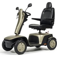
The TRACER electric wheelchair is designed for outdoor use, but it can also be used indoors because of its manoeuvrability and compact construction.
No driving license or insurance policy are required to operate the TRACER electric wheelchair. We do, however suggest that you take out a private insurance policy.
We wish to point out that electromagnetic sources (e.g. mobile phones, etc.) can cause interference and that the wheelchair's electronics can also affect other electric appliances.
Even if you have been instructed by your specialist dealer about the operational elements of your electric wheelchair and their use, we recommend that you read the following pages carefully before you first use it.
APPLICABILITY
The many types of equipment and accessory and the modular construction allow full use by persons disabled by
- Paralysis
- Loss of limbs (leg amputation)
- Limb defects / deformation
- Stiff or damaged joints
Diseases like heart problems, poor circulation, disturbance of balance or "Kachexie" as well as for aged persons.
When considering individual requirements
- body size and weight
- physical and psychological condition
residential circumstances and
the environment
should also be taken into consideration.
Guarantees can only be honoured when the product is used under the specified conditions and for the intended purposes.
CONTENTS OF THE CONSIGNMENT
- The frame structure including the motors, the seat, and the back unit
- Footrests (standard: B06; removable, can be turned aside)
- 2 × batteries including the battery boxes
- Battery charger
- Steering electronics
- Tools (Allen keys)
- Instruction manual
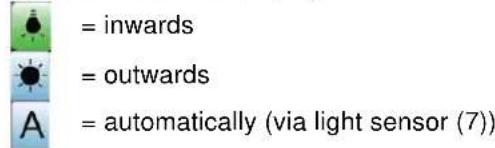
EXPLANATION OF THE SYMBOLS

"ve the safety instructions!"
the instruction manual before use!

on: Parking brakes activated (electronic driving possible)

bn: Parking brakes deactivated (free running and pushing possible, no electronic driving).

g free running, be careful with slopes and inclinations.

rate recovery and recycling of electric and electronic devices
The electric wheelchair is delivered fully assembled. Only the footrests have to be fixed (see the relevant description). Your dealer delivers the wheelchair fully assembled and explains the various operating elements and their use. However, for your own safety we provide a further, detailed explanation of the different parts.
The steering and control unit built into your electric wheelchair enables you to control all the driving, steering and braking processes of the vehicle. The wheelchair's electrical unit and electronics are constantly being monitored internally. Any fault in the electronics is indicated on the steering unit and, if necessary, the wheelchair is switched off for reasons of safety (see the chapter on fault analysis). Consult your specialist dealer if this happens.
The TRACER model can be fitted with equipment which can electrically adjust the inclination of the seat and the backrest, as well as the height of the footrests.
ADJUSTING THE STEERING UNIT
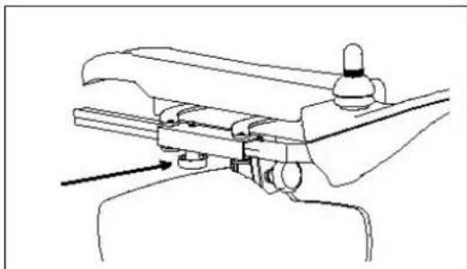
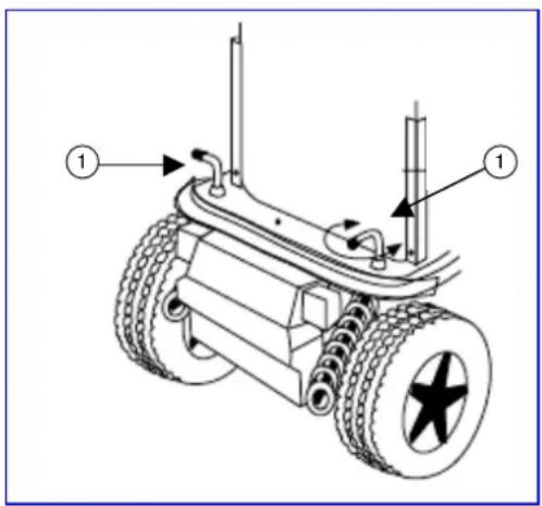
The steering unit's horizontal position can be changed by loosening screw (1). The unit can then be adjusted as desired, or removed. Screw (1) must then be retightened properly. If screw (1) is pulled to the side, the steering unit can be turned to the side.

Make sure that the steering unit's connection cable stays clear of the pincer mechanism.
DX2 STEERING UNIT
The steering and control unit built into your electric wheelchair enables you to control all the vehicle's driving, steering and braking processes and to control other adjusting motors (options: lifting column and seat/back adjuster and leg supports). The wheelchair's electrical unit and electronics are constantly being monitored internally. Any fault in the electronics is indicated on the operating display (6) and the status display (1) and, if necessary, the wheelchair may be switched off for reasons of safety (see the chapter on fault analysis).
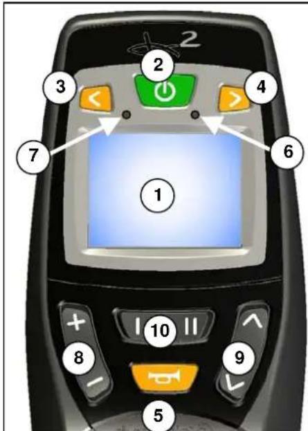
1 = Display (colour)
2 = "ON / OFF" button
3 = "LEFT INDICATOR" + "LIGHT" button
4 = "RIGHT INDICATOR" + "WARNING INDICATOR" button
5 = "HORN" button
6 = Fault code/operating display
7 = Brightness sensor
8 = "DRIVE PROFILE" button
9 = "SELECT FIELD" button
10 = "SELECT MENU" button
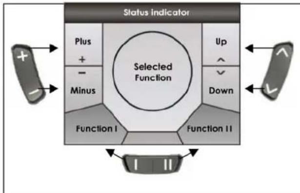
The function buttons (8), (9) and (10) enable functions to be selected that are displayed in the assigned fields on the screen.
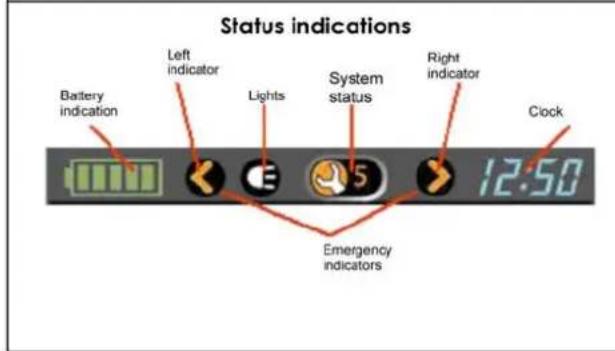
The status display is constantly visible in the upper part of the display and always shows the batteries' charge level and the current time.
The light, indicator and warning light displays only appear when the relevant function is selected. The system status display appears when there is a fault or an event, and displays the relevant event or fault code (1-12).
| Display | Meaning |
| Battery fully charged | |
| Battery fully charged | |
| Battery half charged | |
| Battery will soon be low, charge it | |
| Battery is low, charge it soon | |
| Battery is dead, charge now |
Start the steering / control unit

Press the ON/OFF button (2) and the operating display (6) will briefly flash on and the screen will show the drive level (1-5) last used.
Switch off the steering / control unit

Press the ON/OFF button (2) and the system will switch off.
Lock the steering / control unit

If you keep the ON/OFF button (2) pressed for longer than 4 seconds, the steering unit will be locked.
The lock symbol will briefly appear in the display.
Unlock the steering / control unit

When the ON/OFF button (2) is pressed...

... the lock symbol will appear in the display.

When you press the horn button (5) twice while the lock symbol is showing, the control unit will be unlocked. The drive level (1-5) last used will appear in the display (1-5).
Switch the indicators on/off

To switch the drive direction display on and off, press buttons (3) or (4) for whichever indicator you wish, left or right. When you activate a drive direction, it will flash in the status display.
or
Select the light function using the field selection button (9) and the display will show the light selection menu.
To switch the flash function (left or right) on or off, move the joystick in the appropriate direction left or right.
To switch back to the driving program, select the drive profile button (8) in drive mode.
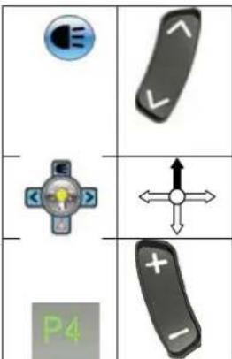
Switch the light on/off

To switch the light on and off, keep the button for the left-hand indicator (3) pressed for longer than 3 seconds. When the light function is switched on its symbol will light up in the status display.
or
Select the light function using the field selection button (9) and the display will show the light selection menu.
Push the joystick upwards to switch the light on or off.
To switch back to the driving program, select the drive profile button (8) in drive mode.
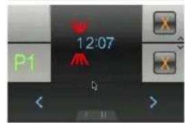
Switch the warning light on/off

To switch the warning light on and off, keep the button for the right-hand indicator (4) pressed for longer than 3 seconds. When the warning light function is switched on its symbol will light up in the status display.
or
Select the light function using the field selection button (9) and the display will show the light selection menu.
Push the joystick downwards to switch the warning light on or off.
To switch back to the driving program, select the drive profile button (8) in drive mode.
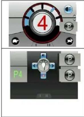
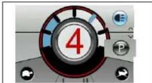
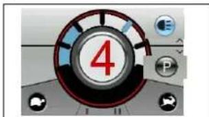
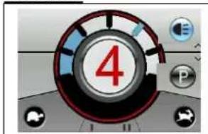
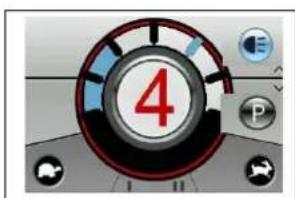
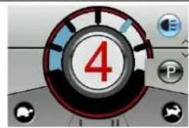
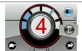
Drive functions
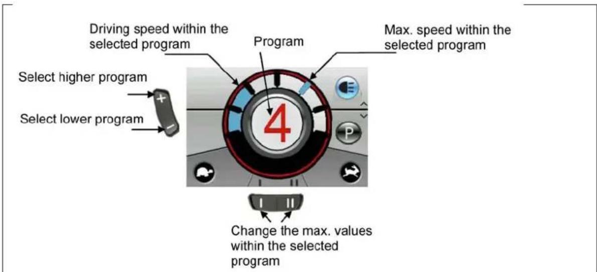
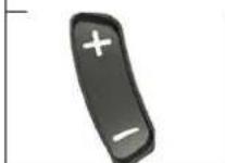

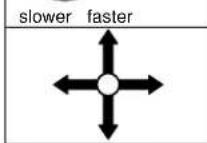
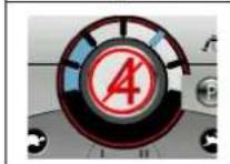
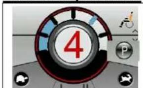
In drive mode use the drive profile button (8) to select a higher or lower driving program (drive profile 1-5). These drive programs are programmed in the factory to rise from slow to fast. The drive program you select appears in red text in the middle of the display.
The top speed in any drive program can be changed using the menu selection button (10) in the drive program selected.
To drive the wheelchair in the direction you wish, move the joystick to the position you want.
If the loading socket is plugged in, the wheelchair will be locked for drive functions. If the joystick is moved, the display will also briefly show a red warning bar.

Make sure that the steering lever is in the neutral (central) position when pressing the on/off button, otherwise the electronics will be blocked. This block can be lifted by switching the control unit off and then on again.

Always adapt your speed to the prevailing environmental conditions.
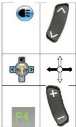
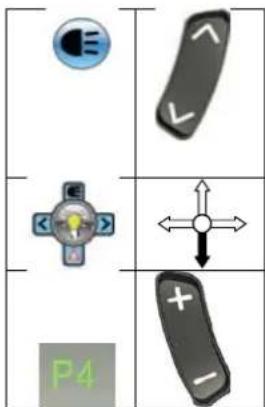
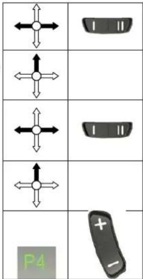
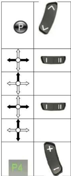
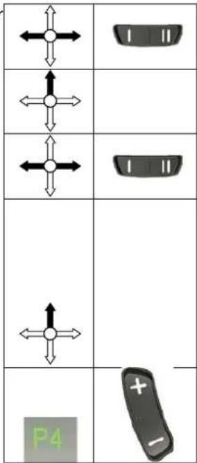
Electric adjustments
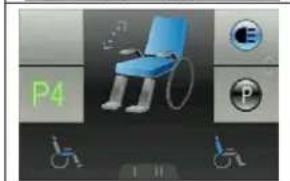
Select the program function using the field selection button (9) and the display will show the menu for the adjust functions.
Select left/right with the joystick or selection button (10) until the adjust function you want appears in the centre of the display.
To adjust the selected function, move the joystick in the direction you want up or down.
| ← | | | | |
| ← | Return function |
| Start function | |
To switch back to the driving program, select the drive profile button (8) in drive mode.
| P4 | + - |
| Adjust function | In Display | Display Menu |
| Seat inclination | ||
| Angle of backrest | ||
| Leg support left | ||
| Leg support right | ||
| Leg supports simultaneous |
The only functions displayed in the menu selection and the centre of the display are those which exist on your wheelchair and have been enabled.

Make sure that no objects and/or persons are inside the swinging range of the adjust functions, since this could cause damage and/or injury.

For your safety the adjust functions can only be activated when all four wheels of the wheelchair are standing still. The driver programs are disabled while the adjust functions are active.
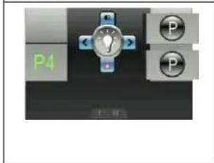
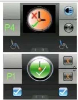
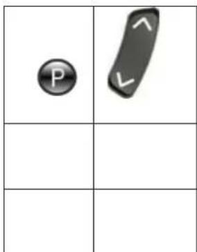
Set time
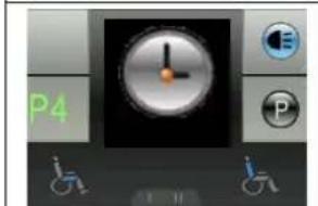
Select the program function using the field selection button (9) and the display will show the menu for the special functions.
Select left/right with the joystick or the menu selection button (10) until the time function you want appears in the centre of the display.
If you want to set the time, confirm by moving the joystick upwards.
The time digit waiting to be set flashes. To change other digits, you can select left/right with the joystick or use the menu selection button (10).
To adjust the digits, select upwards with the joystick.
To save the new time, confirm by moving the joystick downwards.
To switch back to the driving program, select the drive profile button (8) in drive mode.
| P | |
| ←↑ | 1 11 |
| ←↑ | |
| ←↑ | 1 11 |
| ←↑ | |
| ←↑ | |
| P4 | + - |
By default, the factory sets the time to be visible in the status display. To change this option, proceed as follows:
Select the program function using the field selection button (9) and the display will show the menu for the special functions.
| P |
Select left/right with the joystick or the menu selection button (10) until the time function you want appears in the centre of the display.
If you want to change the display option for the time, confirm by moving the joystick upwards.
The option currently selected will appear in the menu and the centre of the display. To change this, select left/right with the joystick or the left/right menu selection button (10).
To save the option you want, confirm by moving the joystick upwards.
To switch back to the driving program, select the drive profile button (8) in drive mode.
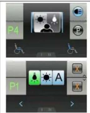
Adjust the screen brightness
Select the program function using the field selection button (9) and the display will show the menu for the special functions.

Select left/right with the joystick or the menu selection button (10) until the brightness function you want appears in the centre of the display.
If you want to change the brightness of the display, confirm by moving the joystick upwards.
Adjust the brightness of the display by moving the joystick left/right or selecting the left/right menu selection button (10).
To save the brightness you have selected, confirm by moving the joystick upwards or downwards.
To switch back to the driving program, select the drive profile button (8) in drive mode.
By default, the factory sets the brightness of the display to be automatically adjusted to match the light conditions. To change this function, proceed as follows:
Select the program function using the field selection button (9) and the display will show the menu for the special functions.
Select left/right with the joystick or the menu selection button (10) until the brightness function you want appears in the centre of the display.
If you want to change the brightness function, confirm by moving the joystick upwards.
Select left/right with the joystick o selection button (10) until the brightness function you want appears in the centre of the display.
If you want to change the brightness function, confirm by moving the joystick upwards.
Adjust the display's brightness function by moving the joystick left/right or selecting the left/right menu selection button (10).
To save the brightness function you have selected, confirm by moving the joystick upwards.
To switch back to the driving program, select the drive profile button (8) in drive mode.
If you have special requirements, you can ask your specialist dealer to enter an individual driving program.
SEAT AND BACK
In the standard version your TRACER has a fixed seat and a fixed backrest which can be adjusted mechanically. As an optional extra the seat can be inclined electrically and the back can also be adjusted electrically.
MECHANICAL ADJUSTMENT OF THE BACK
For easier stowing of the electric wheelchair in a vehicle, the back can be folded down forwards or backwards. Open the lid of the battery box (see the chapter "Removal and replacement of the batteries"). Above the battery box on the right-hand side are bolts which can be pulled out quickly by loosening the clasps. You have now separated the connection between the back and the frame. The backrest can be tilted to the front or to the rear, and removed, after loosening the screw handles on the lower side of the back unit. (The back can be fixed again by reversing this process).
ELECTRIC SEAT INLINE (option)
If you chose the electric seat tilting option, your wheelchair will have been fitted with the system before delivery. To operate this, it is only necessary to switch the steering unit on. The driving program then switches itself on. If you want to adjust the angle of your seat, you just need to use the function button for adjusting the seat. The control indicator on the DX control unit shows that you have selected this
function (on the G90 control unit, the selected symbol flashes). You can then adjust the slope of the seat by pushing the joystick forwards or pulling it backwards.

Make sure that no objects and/or persons are inside the swinging range of the wheelchair, either in front or at the rear, since this could cause damage and/or injury.

For your safety this adjust function can only be activated when all four wheels of the wheelchair are standing still. When this function is selected, the driving program is disabled.
ELECTRIC BACK ADJUSTMENT (option)
The back can be adjusted in a similar way to the seat angle. You only have to select button the relevant button on the steering unit and you can then tilt the back as you wish.

Make sure that no objects and/or persons are inside the swinging range of the wheelchair, either in front or at the rear, since this could cause damage and/or injury.

For your safety this function can only be used when all four wheels of the wheelchair are standing still. When this function is selected, the driving program is disabled.

Make sure that you do not set the backrest too far over backwards, since this can displace the centre of gravity too far to the back and cause tipping over.

For your own safety you should not drive the wheelchair in an inclined or tilted position, since it would severely limit your visibility.
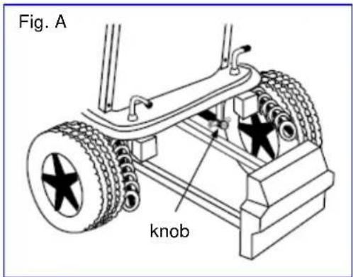
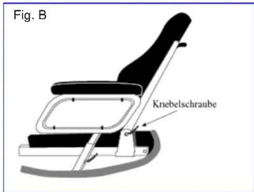
LEG SUPPORTS
The basic model of your electric wheelchair is equipped with leg supports which allow your legs to rest comfortably. You can adjust the length of the foot supports continuously, turn them aside, or even remove them completely. These adjustments should be carried out by a third person with the required technical knowledge. Consult your specialist dealer if these adjustments become necessary. If you want to carry out these adjustments yourself, you should read the following sections carefully.
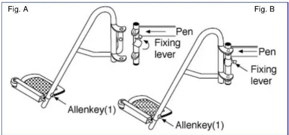
When you want to fix the footrests, hang one leg support sideways on the outside and then turn it inwards until it stops. The fixing lever (Figure B) must point backwards. If the leg supports do not engage immediately, push them lightly inwards. Do the same on the other side. To remove the footrests, reverse this process.

When handling the leg supports, make sure that you hold on to the upper curve to prevent your fingers from getting caught and hurt.
Turn the footplates out of the way for climbing in and out comfortably. The footplates are designed for resting your feet securely on them; in addition, your feet are prevented from moving sideways unnecessarily. Use the Allen keys provided to adjust the length of the leg supports. There is a countersunk Allen screw (Figure A) on the rear side of the leg support for fixing the footplate. By loosening this screw the footplate can be adjusted to the length of your leg. It must be tightened properly afterwards.

Make sure that the footplate is at least 6cm above the ground to avoid scraping the ground when moving. This could damage the wheelchair and endanger its operational safety. The user might also get hurt.

Do not stand on the footplates; they are only designed for letting your feet rest on them.

When the leg supports are adjusted, no persons or parts should be within their reach, otherwise there is danger of injury and/or damage.
If there are patterns of illness and/or disabilities which mean there is no guarantee that your legs would rest constantly on the leg supports, you may select from other available leg supports. Kindly ask your specialist dealer if you have queries in this regard.
ARMRESTS
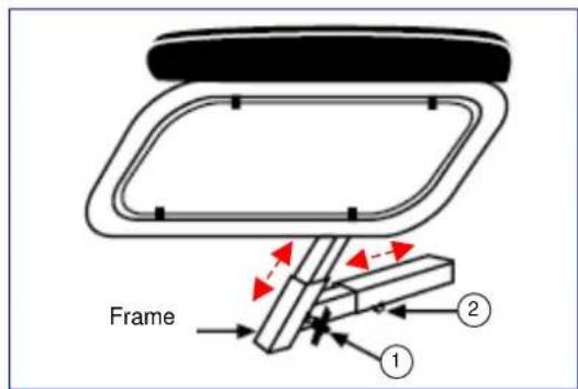
The height of the armrests can be adjusted by loosening screw (1) and pulling the armrest upwards.
To adjust the width between the armrests, you only have to loosen screw (2) and place the armrest in the desired position. The screw must be tightened properly afterwards.

Make sure that all fixing screws are properly tightened before using the wheelchair, otherwise injury and/or damage can be caused.

Never pick the wheelchair up for transportation by grasping the armrests, but take hold of solid frame parts only.
The armrest containing the steering electronics can only be detached if the electronics have been removed previously.

The armrests may only be removed when there is no chance of the wheelchair user falling out sideways.
If changes, damage, or wear of the suspension are noticeable, kindly consult your specialist dealer who can remedy these defects.

To avoid endangering your safety, do not use the wheelchair if you see that the mountings have changed, been damaged, or have worn out.

If you make any changes to the armrests and/or the armrest retainers, you do so entirely at your own risk. Then your insurance claims lapse immediately.
BATTERY CHARGER
To charge the batteries, only use the battery charger supplied - IMPULSE S (8 A).
| Primary voltage | 230 Vac – 50/60 Hz – single phase |
| Secondary nominal voltage | 24 V |
| Secondary maximum voltage | 35 V |
| Secondary power | max. 8 A |
| Battery type | Lead-sulphuric acid: gel |
| Battery capacity | 60 Ah – 85 Ah (80% capacity charged within 8 hours) |
| Safeguards | Protected against reverse polarisation, electrical surges and extreme temperature |
| Nominal output | 270 W |
| Efficiency | min. 80% (when fully loaded) |
| Ambient temperature | 0°C to +40°C |
| Unit dimensions | H 70 x W 150 x D 200 mm |
| Protection range | IP 21, Protection Class II |
| Total weight | Approx. 1.3 kg |
| Mains cable length | 1.9 m |
| Charge cable length | 2.4 m |
| Ambient storage temperature | -15°C to +50°C |
| Relative storage humidity | max. 95% (non-condensing) |
| Conformity | EMC Directive 89/336/EEC Low Voltage Directive 73/23/EEC |
We reserve the right to introduce technical changes.
CHARGING THE BATTERIES
As the IMPULSE S (8 A) charger aligns the charge curve with the AGM batteries' charge level, you can recharge your wheelchair after each use. This avoids any aggressive battery charging and the "memory effect".
Recharge the wheelchair, at the latest, when the charge indicator on the steering unit goes into the red zone. If, despite this, you continue driving, eventually only the last red diode lights up and flashes continually, indicating that the batteries are nearly flat. If you disregard this warning signal, too, an error message will shortly appear indicating that the batteries can no longer provide power for driving. The batteries should therefore be charged before these error messages appear, using the supplied battery charger IMPULSE S (8 A). Avoid the batteries becoming drained, in any case.
- SETTING UP THE CHARGER
When setting up the charger, ensure that it is well-ventilated on all sides. A minimum of 10cm space should be left free around the unit for this purpose. If the charger is insufficiently ventilated so that the unit heats up, the charging rate will fall which will extend the charging time. If the charger overheats (> + 50^) , it will stop charging.
The charger should only be used from a wall socket with a voltage of 230V - 50 / 60Hz and in wellventilated, dry areas.
FIRSTUSE
First put the plug into the wall socket. After an LED combination has lit up, the charger switches to STANDBY. Both LEDs (green and yellow) are active.
Next, connect the charger cable with the three-pin plug to the loader socket on the electric wheelchair's steering unit. Once connected to the batteries, the charger automatically begins charging. Now only the yellow LED is active.
When charging is complete, the yellow LED goes out and the green LED comes on. Now remove the charger cable from the steering unit. The charger switches back to STAND-BY mode (yellow and green LEDs active).
If the charger cable is not removed, a tiny current will keep the batteries topped up (trickle charging).

When charging is complete, always remove the plug from the steering unit first and only then the mains plug from the wall socket.
- INDICATORS
| Yellow LED | Green LED | |
| Charger switched off (not plugged into the mains) | ○ | ○ |
| Charger has just been switched on and displays the charging characteristic that has been set | ◎ | ○ |
| ○ | ◎ | |
| Stand-by | ● | ● |
| Charging | ● | ○ |
| Full | ○ | ● |
| Fault | ◎ | ◎ |
| ○ = Off ● = On ○ = Flashing | ||
If you decide not to use your electric wheelchair for an appreciable period, you must nevertheless recharge it regularly to keep it in a running condition ready for immediate use.

If the batteries are not used for an appreciable period, they discharge slowly by themselves (drainage). Then it becomes impossible to recharge them with the battery charger supplied. So charge the batteries at least once a month even if they are not being used.

Only use the battery charger supplied to charge the batteries.

The manufacturer accepts no liability for damage caused by improper charging.

Never interrupt the charging cycle. The charger shows when the charging cycle is finished. (green LED remains active).
For further information, please refer to the user instructions provided with the charger.
BATTERIES
The standard for your electric wheelchair is two closed, 12V/70Ah AGM batteries. The batteries used with your electric wheelchair are drive batteries which only attain full capacity after a few charging and use cycles.
If the batteries lose their power after long usage, or if they are damaged, get them both replaced by a specialist dealer only.

We accept no liability for damage caused through using other types of battery.

Do not use the batteries below +5^ or above +50^ (the ideal is: +20^ ).

If the batteries are opened, all manufacturer liability and all claims will become void.
REMOVAL AND REPLACEMENT OF THE BATTERIES
Kindly obey the following instructions when removing the batteries for servicing or for transportation:
Pull up the knobs (1) and pull the battery drawer backwards. Now you can grasp the first battery by its handle and pull it backwards on the rail. Then you can lift the first battery out of the wheelchair by means of the handgrip on the battery box. To remove the second battery box, push your hand beneath the battery box. There is a hollow which allows you to take hold of the battery box from below and pull it backwards with a slight upwards motion.
Now this battery box can also be lifted out of the wheelchair by grasping the handle. When replacing the battery boxes, you reverse the process and only need to push the battery boxes backwards.

To avoid bruising, make sure that your hands are not caught between the handle and the frame tube when battery boxes are pulled out.

Make sure that the batteries are safely put down outside the wheelchair.

When replacing the batteries, make sure that they are positioned correctly and that the plugs on the battery boxes are on the left side.

Both connectors of the battery boxes, one at the front and the other at the rear, must be plugged in first, otherwise there is no connection to the electronics.

Make sure that the plugs are connected properly after replacing the battery boxes. If the rear cover does not fit over the knobs (1), it means that the plugs have not connected properly.
When transporting the wheelchair, it is not necessary to remove the batteries from their boxes. When removal of the batteries becomes necessary (e.g. replacing the batteries), note the following:
-
Remove the battery box lid by loosening the screws on the handle.
-
Lift the lid off.
-
Put the handle back on the battery to allow it to be carried.
- On one side the battery box is connected to the battery by an Allen screw. Unscrew this and remove it.
- The battery can be lifted out of the battery box by the handle after the pole clamps have been removed.
- Reverse these processes when replacing the batteries.
#
These tasks should be undertaken by the specialist dealer.
Make sure that no tools or other conducting objects make contact with both poles of the batteries, or the resulting electric currents can cause injuries.
No work involving the batteries and the electronics should be undertaken in damp conditions.
When connecting the batteries, you should consult the circuit diagram on the battery box lid.
The manufacturer is not liable for damage/injury caused by improper handling.
BATTERY CONNECTIONS

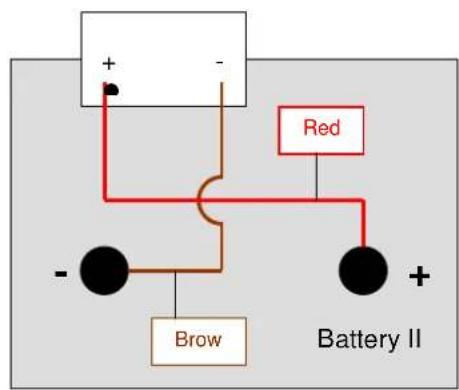
BATTERY STORAGE
If you do not use your wheelchair for a long while, you can leave it connected to the battery charger. Charging is automatically controlled by the battery charger. If you remove and store the batteries, kindly note the following:
- Remove the cable clamps from the poles of the battery.
- The positive pole must be covered by at least one pole cap.
- Only grasp the batteries by two opposite sides of the unit.
- Ensure no objects get in between the poles (a short-circuit could occur!).
- Batteries should only be stored in dry, well-ventilated spaces at a temperature between +5^ and +45^ .
- Leave batteries in their battery boxes so they are protected from damp, etc.
- Protect the plugs and sockets of the battery boxes against corrosion.
- Protect the batteries against drainage (see "Charging the batteries" section).

If batteries are not used, they can completely drain.
Your dealer will be happy to advise you on storage and with inspecting your batteries.
THERMAL FUSES
To protect the motor against overload, on the right side of the seat frame there is a thermal fuse that will automatically cut off the motor to prevent overheating and thus rapid wear and tear or breakdowns. This can occur if you go up or down slopes that exceed the maximum gradient indicated. Nominal loads exceeding the maximum could also trigger the safety mechanism. If you try to drive with the brakes on, it could also result in overload. The values to comply with are indicated in the "Technical Details" section. To be able to use the wheelchair again, remove the overload and wait till the motor has cooled off, and then gently press in the thermal fuse again. The system is now ready for use again.
PARKING BRAKES
In addition to electromagnetic braking, your electric wheelchair can also be equipped with fixed braking for each driving wheel. These must then be set for the wheels. When pneumatic tyres are used, the parking brake can only function when the tyres are inflated hard enough (see the section "Technical details").
Note that the tyre pressure should always correspond to the values given in the section "Technical details", otherwise the action of the parking brakes would be reduced or even be zero.
Note that the parking brakes are not supposed to be used for braking while driving. The real function of the parking brakes is to prevent the wheelchair from rolling away after it has stopped. If it is used for reducing the speed while driving, injury and/or damage could result.
If the brakes lose their function through wear and tear and/or the covers and hoses have been damaged, we advise you to consult your specialist dealer who has the tools and the knowledge for repairing / replacing the defective parts.
When unsuitable tools are used or through improper maintenance damage and/or loss of function could result.
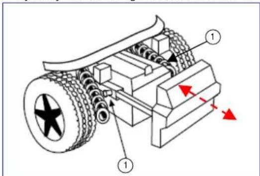
If you wish to adjust the parking brakes yourself, use a suitable Allen key to loosen the two screws which hold the brake suspension on the rail. Then push the brake unit to the desired position and retighten the two Allen screws and check whether the braking action is correct.
Brake adjustments not complying with the manufacturer's instructions are done at your own risk (only in the case of built-in parking brakes). No liability is applicable.
Rather let your dealer adjust the parking brakes; he is trained on our products and will comply with all relevant prescribed safety measures.
Note that the parking brakes are not supposed to be used for braking while driving. The real function of the parking brakes is to prevent the wheelchair from rolling away after it has stopped. If it is used for reducing the driving speed, injuries could follow.
If you are not satisfied with the braking behaviour of your wheelchair, consult your specialist dealer immediately; he will then adjust the brakes properly.
If water, oil, or other kinds of dirt have soiled the wheels of the wheelchair, then the braking action of the parking brakes would be impaired. Check the condition of the wheels every time before using the wheelchair.
If the brakes lose their effectiveness because of wear and tear and/or damage to the tyres/inner tubes, kindly consult your specialist dealer, since special machines are required for changing the "PU" tyres. The end-user is not able to change the "PU" tyres.
TYRES
The TRACER electric wheelchair is fitted with 3.00-8 driving wheels (standard pneumatic) and 260x85 steering wheels (standard pneumatic). Consult your specialist dealer about other wheel combinations. He will advise you as to which combinations are suitable for your individual requirements.

Make sure that the wheels are always inflated correctly, otherwise the driving behaviour might be affected. The correct pressures for the tyres are given in the chapter "Technical details". In addition, you should always check the pressure values appearing on the tyres themselves.

We do not provide any guarantee for wheels not supplied by the manufacturer.
TYRE CHANGING
If you want to change the tyres or inner tubes, you should note the following:
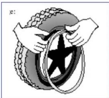
Before you can remove a tyre, you must let all the air out of the tube, and insert a tyre lever between the tyre and the rim. Then slowly and carefully push the lever downwards. This will pull the tyre over the edge of the rim. If you then move the lever along the rim, the tyre will jump out. Now carefully remove the tyre from the rim and then remove the tube.

There must be no air in the tube before it can be removed.

If handled improperly, the rim might be damaged. We recommend you get your dealer to do this work.
Note the following before inserting the new inner tube:
Check the rim bed and the inside wall of the tyre for foreign matter and clean these properly if necessary. Check the condition of the rim bed, especially around the position of the air valve. Please use only genuine original replacement parts. No liability is accepted for damage caused by non-genuine replacement parts. Kindly contact your specialist dealer.
WHEN PLASTIC RIMS ARE USED
Place the rim belt in position over the air valve before inserting it into the rim. Then the rim belt can be pulled over easily. Check whether all spoke heads are covered (in the case of a plastic rim a rim belt is not required).
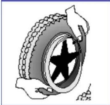
Push the tyre over the edge of the rim, starting behind the air valve. Inflate the tube slightly until it is round, and place it inside the tyre.

If the inner tube fits snugly inside the tyre without any folds (if there are folds, let some air out), then you can push the upper side of the tyre gently onto the rim with both hands, beginning behind the airvalve.
Check all around on both sides that the tube is not pinched between the rim and the edge of the tyre. Lightly push the air valve inwards and pull it out again to make sure that the tyre is positioned properly in the region of the air valve.
To ensure that the wheel is inflated correctly, admit only so much air initially that the tyre can still be easily pushed inwards by using your thumbs. If the check-lines are equidistant from the edge of the rim on both sides of the tyre, then the tyre is centered properly. If not - let out the air and position the tyre afresh.
Now the tyre can be inflated to its full operating pressure (note the maximum) and the valve cap should be replaced.
WHEN ALUMINIUM RIMS ARE USED
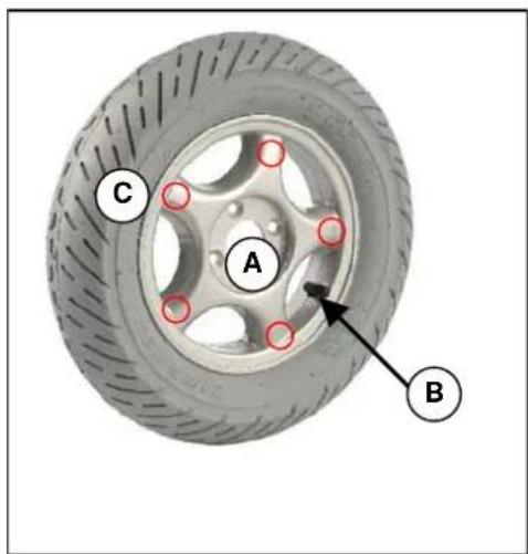
STEERING WHEELS
A. Loosen the screw on the steering wheel axle and remove it from the steering wheel fork.
B. Let the air out of the steering wheel by lightly pressing the pressure pin on the valve.
C. Loosen the 5 screws that hold the split rim together. Now separate the rim sides.
ASSEMBLY
Insert the partly-filled inner tube into the tyre.
C. Connect the two sides of the rim through the tyres and use the 5 connecting screws to screw the rim together.
B. Make sure that the valve juts out of the valve opening in the rim.
A. Put the wheel back into the front wheel fork and inflate the wheel.
Before taking the rim apart always let the air out of the tyres, or the sides of the rim could come apart explosively and cause injury!
Make sure that the inner tube does not get caught in the sides of the rim
Only inflate the wheels to the max. tyre pressure (see "Technical details")
A
Check to see that all the screws on the wheels are firmly tightened before using the wheelchair.
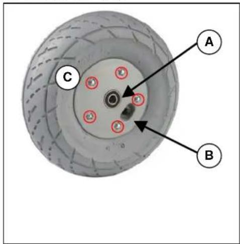
DRIVE WHEELS
A. Unscrew and remove the axle nut on the drive wheel and the 4 screws that attach the wheel to the flange.
B. Let the air out of the wheel by lightly pressing the pressure pin on the valve.
C. Unscrew the 5 screws on the inside of the rim. Separate the rim sides.
ASSEMBLY
Insert the partly-filled inner tube into the tyre.
C. Connect the two sides of the rim through the tyres and screw them back again.
B. Put the valve through the hole for it in the rim.
A. Put the wheel back on the flange and secure the wheel by hand-tightening the axle nut. Inflate the wheel to the recommended tyre pressure.
Before disassembling the rims, always let the air out of the tyres!
When assembling, make sure that the inner tube does not get caught between the sides of the rim.
A
Only inflate the wheels to the max. tyre pressure (see "Technical details")
Check to see that all the screws on the wheels are firmly tightened before using the wheelchair.
Screw adhesive (e.g. Loctite) should be applied to the screws on the flange. Screw adhesive will only work if the thread is free of grease and particles.
A
Improper assembly voids any warranty claim.

When inflating the tyres, always check that the pressure is correct. The correct pressure is given on the tyre walls (also refer to "Technical details").

Use only inflating equipment which complies with regulations and indicates the pressure in bar, or use the supplied air pump. We do not accept any liability for damage caused by using inflation equipment not supplied by the manufacturer.
PUSHING THE WHEELCHAIR
The wheelchair can be pushed by an attendant. Turn the locking lever outwards (inwards in the case of the TRACER 50+ ); this allows the wheelchair to be pushed freely. Now the wheelchair will no longer be driven by the motors, nor will it be braked by the motors.
When pushing the wheelchair, make sure that the controls are switched off and that you only push it on level terrain.

When the locking lever is in this direction, edriving is enabled; the electromagnetic brake is activated.

When the locking lever is in this direction, your wheelchair is in the free-wheeling position; the electromagnetic brake is deactivated.

Without the braking effect of the motors which is absent when the wheelchair is being pushed, the wheelchair can accidentally move or turn. (Use the parking brakes to secure the wheelchair!).
TRANSPORTING THE WHEELCHAIR
Before lifting up the wheelchair, all moveable parts must be dismantled (footrests, armrests, and steering unit).

When raising the wheelchair, it should only be grasped by fixed parts of the frame.

To prevent damage, the steering unit and armrests should be removed for transportation.

When assembling, make sure that all screws are retightened properly.
To prevent the wheelchair from moving about, switch the locking mechanism behind the backrest to electronic driving (it must be engaged). In addition, engage the parking brakes if present in your model. If you require further belt securing systems, make sure that they are only attached to solid parts of the frame.
If you want to be taken up or down stairs with the wheelchair, you will need a wheelchair ramp or wheelchair lift system.

At least two persons are required to move the wheelchair up or down stairs or over single steps.

When being transported, no persons or objects should be below the wheelchair, to prevent personal injury or damage to the wheelchair.
TRANSPORTING BY CAR
When inside a vehicle the wheelchair must be securely fastened by means of the built-in safety belts or by specially provided belt systems.

Nobody is permitted to sit in a wheelchair which is transported in a vehicle.

Make sure that the wheelchair is fastened by fixed parts of the frame only.
Check that the wheelchair cannot slide in any direction.

Engage all parking brakes in addition to the electromagnetic brake of the wheelchair.
Loose parts taken from the wheelchair must be stowed securely.
For transportation by public vehicles for disabled persons you should request information from the organisation concerned about compliance with the currently applicable prescriptions and norms for such transport.
For transportation in other vehicles (airplanes, buses, ships, trains, trains, etc.) you should consult the operator concerned about whether you and your wheelchair could be safely transported according to the relevant rules and norms.

We do not accept any liability for damage and/or injuries resulting from transportation by third parties. Transportation is at your own risk.
If you have further questions about transportation, kindly consult your specialist dealer. He/she shall gladly assist you further.
USING RAMPS
If you are considering ramps for overcoming obstacles, kindly note the following:
For your own safety you should drive on ramps at the slowest possible speed. If the wheelchair has optional adjustment functions, ensure that
- the back has been set to upright (if there is one)
- the angled seat has been set to horizontal (if there is one)
- the leg supports have been set so that no collision can occur while passing the obstacle.

The manufacturer can accept no liability for any damage or injury that may arise from the adjustment functions being extended when being used on a ramp.
If another person is pushing you, note that the large weight of the electric wheelchair exerts appreciable reverse forces.
If your helper does not have the strength to push the wheelchair up the ramp, you must immediately secure it by engaging the motor adjustment (Notstop).

Observe the instructions on the maximum load of the ramps used.

Use a restraining safety belt to secure yourself in your wheelchair.

We do not accept any liability for injury or damage caused by an improper choice of ramps.
ACCESSIONS
- INDIVIDUAL HEADREST (L55)
The standard backrest can be enhanced by an individually adjustable head support supplied by us. This comprises a cushioned headrest which can be set in various positions by means of a gearwheel (see diagram).
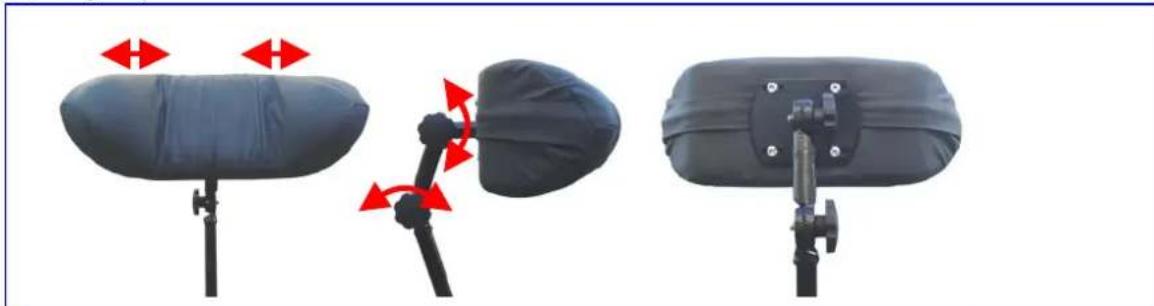
The receptacle screwed in the upper third of the back, can be fixed to the centre of the back for inserting the headrest. The height of the headrest can be adjusted and then tightened at the desired height. The holes required for fixing the headrest have already been drilled in the back unit.

Make sure that the headrest is inserted at least to the marked position to be fixed securely and reliably.
The depth of the headrest can be adjusted by slightly loosening the adjusting screws to allow movement of the sprocket gears. Then you can adjust the headrest to your needs and secure it by retightening the adjusting screws. If the adjusted position is not satisfactory, you can repeat this process.

Ensure that the back of your head is supported when relaxed in an upright sitting position.

Before using the headrest all fixing screws must be tightened properly, since injuries might result when it slips downwards unintentionally.
You can secure your head against tipping sideways by lightly pressing the side panels of the headrest inwards and to the front.

Do not exert too much pressure on the side panels otherwise bruising may result.

Do not clap the side panels together violently, otherwise they might break off, causing possible injury as well as loss of function.
Structural alterations to the headrest would void any warranty.
- LEG SUPPORTS
If the leg supports supplied with the wheelchair do not meet your requirements, you could consider leg supports with adjustable height. Because the footrest attachment is standardised, it can be assembled in the same way as described in the section on foot supports.
Kindly consult your specialist dealer if you have questions about other footrest systems; he shall gladly advise you about the indication and function of our available foot supports.
- PERSONAL SAFETY SYSTEM (B58)
For your safety we offer you a standardised safety belt which is equipped with a snap-on fastener, like those mounted in cars and vans. This can be fixed by means of bolts inserted in the bolt holes on both sides of the seat frame next to the backframe attachments. To ensure proper fixing, self-locking ("nylock") nuts should be used.
If the belt has been dismantled, only new genuine nuts provided by the manufacturer should be used for re-attachment.

To ensure the validity of the warranty, entrust this work to your specialist dealer.

Before using the seatbelt, make sure that all screws are properly tightened.
Please consult your specialist dealer if you require other safety belt systems. He/she shall gladly assist you further.
BODY SUPPORTS (L04)
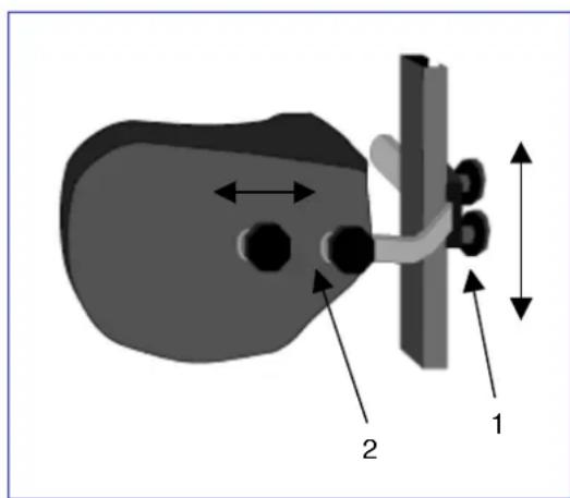
If your upper body requires stronger bracing than that provided by the standard backrest, we offer a lateral support system which can be mounted on the backrest. The guiding rail is mounted vertically about 6cm behind the backrest to one side. The screw threads set in the back, can be used for this purpose (older models can be upgraded by using wood screws). The supporting rods are inserted from the rear and secured by the two Phillips screws. When adjusting the height and depth of the supports, slightly loosen the Philips screws (1) and position the supports to your liking. Then retighten the Philips screws (1).
To adjust the depth of the supports, you can loosen screws (2) and set them to the desired depth.
Make sure that all screws are properly tightened after the assembly, otherwise the stability of the supports is endangered, and injury/damage can occur.
Make sure that the rail system is properly mounted and that nothing obstructs its functional integrity.
If the wheelchair is not fully assembled when delivered, only your specialist dealer who has suitable tools and knowledge of the fittings, may perform the mounting procedure.
Improper assembly leading to damage voids any warranty claim.
While the body supports are fitted, you should sit still and in a natural position in your wheelchair to allow correct fitting.
Make sure that no objects and/or body parts are located between the supports and the back of the supports when they are pulled tight, otherwise bruising and/or damage might occur.
If you have further questions about the indications and function of the supports, kindly contact your specialist dealer. He will be happy to answer your questions.
FOR YOUR SAFETY
Some safety tips are given below for your security:
To prevent injury and/or damage to your wheelchair, make sure that no objects and/or body parts are caught in the spokes of the driving wheels.
Do not step on the footplate when getting in or out of the wheelchair. The footplates must be folded up beforehand, or the leg supports should be swung outwards out of the way.
You should investigate the effects of shifting the centre of gravity on the behaviour of the wheelchair for example on gradients, on laterally sloping ground, or when overcoming obstacles, only when a helper is present to secure and support you.
If you want to pick up something (lying in front of, on the side, or to the rear of the wheelchair), you should not lean too far out to avoid tipping over because of the displacement of the centre of gravity.
Always follow the instructions for using your wheelchair. For example, avoid driving without brakes against an obstacle (step, edge of the curb) or dropping down from steps.
Stairs may only be negotiated when aided by another person. If devices and furnishings like ramps or lifts are available, use them.
Check that the profile depth of the tyres is adequate.
Obey traffic regulations when driving on public roads.
When driving your wheelchair, you should not be under the influence of alcohol or medicine as in the case of driving other vehicles. This also applies to indoor driving.
When travelling outdoors, adapt your driving to weather and traffic conditions.
Check that the rear reflectors of your wheelchair are not covered by dirt and/or other objects.
When driving in the dark, wear bright clothing to be more visible, or clothing with reflectors, and make sure that the reflectors of the wheelchair are clearly visible.
Be careful when using sources of fire such as cigarettes, since they can set the seat and back covers alight.
Make sure that the maximum load (125 kg for the TRACER / 150 kg for the TRACER 50+) is not exceeded.
MAKING REGULAR CHECKS
As with any technical product, your wheelchair, too, requires regular checks if it is to be kept fully-functional. The steps to be taken to fully enjoy the advantages of your wheelchair even after protracted use, are described below.
BEFORE DRIVING
- Check the tyres for visible damage and/or soiling. Remove any dirt as it could impair the motion and road-holding capacity of the tyres. When a tyre is damaged, please go see an authorized workshop for repair.
- Use the drive electronics' display to check that the driving, braking and adjustment features are fully-functional. If these functions are impaired, contact your dealer.
- Check the pressure of the tyres and inflate them if necessary (see section "Technical details").
- Make sure that all screws are tightened properly.
APPROX.EVERY8 WEEKS
Depending on the frequency of use check the following:
- That the armrests are working
- Movable parts of the footrests
- The condition of the covers and cushioning materials.
- The tread depth of the wheels
APPROX.EVERY 6 MONTHS
Depending on the frequency of use check the following:
- Cleanliness
- General condition
- That the charger is working
- Operation of the steering wheels If the rotation resistance is too great, clean the bearings of the steering wheels. If this is insufficient, please consult your dealer.

In cases of lost functionality, repairs and inspections, consult your dealer.
CARE
Your electric wheelchair requires regular care to keep it in a pleasant condition. To do this, note the following:

Steam or high-pressure cleaning is forbidden!
COVERS
Clean the covers with hot water. You can remove stubborn dirt by washing with a mild commercial detergent. Stains can be removed by using a sponge or a soft brush.

Do not use strong cleaning liquids like solvents, nor use hard brushes.

We shall decline all liability for damage caused by the use of improper cleaning agents.

Take care that you do not soak the covers.
- PLASTIC PARTS
Clean all plastic parts of your wheelchair with commercial plastic cleaners. Read the specific product information and only use soft sponges or cloths.
- SURFACE LAYERS
The high quality of the surface layer guarantees optimal protection against corrosion. If the outside of the frame has been damaged by scratches or otherwise, you can protect the area by applying varnish obtainable from your specialist dealer.
ELECTRONICS CASING
Only wipe the steering unit with a cloth moistened by a few drops of a commercial domestic cleaner. Do not use any abrasives or sharp-edged polishing equipment like a metal scrubber or brush, since these can scratch the surface of the steering unit and destroy its water repelling property.

Regularly check the plug connectors for corrosion or damage, since it could affect the efficiency of the electronics.

Before any maintenance work, disconnect the batteries to prevent any unwanted current flow.

The manufacturer accepts no liability for damage caused by poor maintenance.
INSPECTION
In principle we recommend annual inspections, but at least before usage is resumed. The following checks must at least be performed and documented by authorized persons:
- Check the cabling (especially for: crushing, abrasion, cuts, visible insulation of the inner conductor, visible metallic veins, kinks, lumpiness, color changes of the outer sleeve, brittle spots)
- Visual inspection of the frame parts to check for plastic deformation and/or wear and tear (basic frame, seat frame, back frame, side parts, leg supports, motor suspensions)
Electric leads to be securely placed to avoid shearing, crushing and other mechanical stresses and strains. - Visually check all housings for damage, screws must be securely fixed, seals and gaskets should not exhibit visible damage.
Review the charger's residual diversion current ( A) based on VDE 0702
Review the charger's insulation resistance ( MO) based on VDE 0702 - Check the functioning of the armrests and leg supports (locking, load, deformation, wear and tear caused by loads).
- Check the functioning of the drives (during a test drive noises, speed, free running, etc.), if necessary: Measure the performance, first with no load, and then with the nominal load ("SWL") to investigate the wear and tear of the motors by comparing the values of the electric current with the values at delivery, condition and function of the carbon rod, the condition of the collector, remove debris from the motor housing and the collector, etc.)
- Check the condition of the batteries, covers, tubes, and tyres.
Checking measurements may only be carried out by skilled persons trained on the wheelchair at least and at least under the supervision of an electrician who knows the checking instruments and processes. Only an electrician is able to release the electric wheelchair for use after successful checking measurements or servicing. The service must be confirmed in the service plan when at least the above-mentioned aspects have been checked.

The manufacturer is not liable for damage caused by deficient or improper inspections.
DISINFECTION
Only a hygiene technician or someone appointed by him can disinfect your wheelchair and this should be done every time before its use is resumed or before it is provided to a different person. All parts of the wheelchair can be treated with a disinfectant cloth. In principle all surfaces of a system or a product have to be disinfected before passing it on to another user, or when it is known that the user carries an infective vector. In these cases the measures of the federal law on epidemics have to be considered.
Disinfectants may only be applied by authorised persons trained in the functioning and application of disinfectants.

Wear suitable protective clothing because the disinfectants can irritate the skin on contact. For this purpose you should also take note of the product information for the solutions concerned.

You employ unauthorised persons at your own risk.

No liability is accepted by the manufacturer of the wheelchair for damage and injury caused by the improper handling of disinfectants.
We recommend the following disinfectants for scrubbing (based on the list of the Robert Koch Institute, RKI):
| Active substance | Name | Washing-disinfection | Surfacedisinfection(scrub-washingdisinfection) | Disinfecting excretions1 part sputum or stool + 2 partsdiluted solution or 1 part urine + 1part diluted solution | Effectiverange | ManufacturerorSupplier | |||||||
| Sputum | Stools | Urine | |||||||||||
| Diluted solution | Time to take effect | Diluted solution | Time to take effect | Diluted solution | Time to take effect | Diluted solution | Time to take effect | Diluted solution | Time to take effect | ||||
| % | Hrs. | % | Hrs. | % | Hrs. | % | Hrs. | % | Hrs. | ||||
| Phenol orphenol derivatives | Amocid | 1 | 12 | 5 | 6 | 5 | 4 | 5 | 6 | 5 | 2 | A | Lysoform |
| Gevisol | 0,5 | 12 | 5 | 4 | 5 | 4 | 5 | 6 | 5 | 2 | A | Schülke & Mayr | |
| Helipur | 6 | 4 | 6 | 4 | 6 | 6 | 6 | 2 | A | B.Braun Petzold | |||
| m-cresol soapsolution DAB 6 | 1 | 12 | 5 | 4 | A | ||||||||
| Mucocit-F 2000 | 1 | 12 | A | Merz | |||||||||
| Phenol | 1 | 12 | 3 | 2 | A | ||||||||
| Velicin forte | 5 | 4 | 5 | 6 | A | Ecolab | |||||||
| Chlorine, organic orinorganic substanceswith active chlorine | Chloramine-T DAB9 | 1,5 | 12 | 2,5 | 2 | 5 | 4 | A1B | |||||
| Clorina | 1,5 | 12 | 2,5 | 2 | 5 | 4 | A1B | Lysoform | |||||
| Trichlorol | 2 | 12 | 3 | 2 | 6 | 4 | A1B | Lysoform | |||||
| Percompounds | Apesin AP1002 | 4 | 4 | AB | Tana Chemie | ||||||||
| Pure Dismozon2 | 4 | 1 | AB | Bode Chemie | |||||||||
| Perform2 | 3 | 4 | AB | Schülke & Mayr | |||||||||
| Wofesterik | 2 | 4 | AB | Kesla Pharma | |||||||||
| Formaldehydeand/or aldehydes orderivatives | Aldasan 2000 | 4 | 4 | AB | Lysoform | ||||||||
| AntisepticaSurfaceDisinfection 7 | 3 | 6 | AB | Antiseptica | |||||||||
| Aldospray Conc. | 3 | 4 | AB | Lysoform | |||||||||
| Apesin AP30 | 5 | 4 | A | Tana Chemie | |||||||||
| Bacillocid Spezial | 6 | 4 | AB | Bode Chemie | |||||||||
| Buraton 10F | 3 | 4 | AB | Schülke & Mayr | |||||||||
| Desomed A 2000 | 3 | 6 | AB | Desomed | |||||||||
| Hospital dis-infection cleaner | 8 | 6 | AB | Dreiturm | |||||||||
| Desomed Perfekt | 7 | 4 | A | Desomed | |||||||||
| Fink-Antisept B | 8 | 6 | AB | FINKTEC | |||||||||
| Formaldehydesolution DAB 10(formalin) | 1,5 | 12 | 3 | 4 | AB | Ecolab | |||||||
| Incidin perfekt | 1 | 12 | 3 | 4 | AB | Bode Chemie | |||||||
| Kohrsolin | 2 | 12 | 3 | 4 | AB | Schülke & Mayr | |||||||
| Lyso FD 10 | 3 | 4 | AB | Lysoform | |||||||||
| Lysoform | 4 | 12 | 5 | 6 | AB | Lysoform | |||||||
| Lysoformin | 3 | 12 | 5 | 6 | AB | Lysoform | |||||||
| Lysoformin 2000 | 4 | 6 | AB | Lysoform | |||||||||
| Melsept | 2 | 12 | 4 | 6 | AB | B.Braun Petzold | |||||||
| Melsitt | 4 | 12 | 10 | 4 | AB | B.Braun Petzold | |||||||
(…)
| Active substance | Name | Washing-disinfection | Surfacedisinfection(scrub-washingdisinfection) | Disinfecting excretions1 part sputum or stool + 2 partsdiluted solution or 1 part urine + 1part diluted solution | Effectiverange | ManufacturerorSupplier | |||||
| Sputum | Stools | Urine | |||||||||
| Diluted solution% | Time to take effectHrs. | Diluted solution% | Time to take effectHrs. | Diluted solution% | Time to take effectHrs. | Diluted solution% | Time to take effectHrs. | ||||
| Formaldehydeand/or aldehydes orderivatives | MinutilMultidor | 2 | 12 | 6 | 4 | AB | Ecolab | ||||
| 3 | 6 | AB | Ecolab | ||||||||
| Nuscosept | 5 | 4 | AB | Dr.Nusken Chemie | |||||||
| Optisept | 7 | 4 | A | Dr.Schumacher | |||||||
| Pursept-FD | 7 | 4 | \( AB^* \) | Merz | |||||||
| Septoclean FDN | 3 | 6 | AB | Haka Kunz | |||||||
| Tegodor | 3 | 6 | AB | Goldschmidt | |||||||
| Ultrasol F | 3 | 12 | 5 | 4 | AB | Fresenius | |||||
| Franko-DES | 2 | 12 | A | Franken | |||||||
| Tensodur 103 | 2 | 12 | A | MFH>Marienfelde< | |||||||
| Lime-wash \( {}^{s} \) | 20 | 6 | \( A-B \) | ||||||||
Insufficiently effective against myco-bacteria when disinfecting surfaces, especially in the presence of blood. Not suitable for disinfecting blood-contaminated or porous surfaces (e.g. raw wood).
Useless for tuberculosis: preparation of lime-wash; 1 part dissolved lime (calcium hydroxide) + 3 parts water.
*Virus effectiveness tested in compliance with the RKI test method [German Federal Health Circular 38 (1995) 242].
A: suitable for killing vegetative bacterial germs including myco-bacteria as well as fungi, including fungal spores.
B: suitable for deactivating viruses.
The current state of the disinfectants included in the RKI list can be ascertained at the Robert Koch Institute (Home page: www.rki.de).
All steps taken for disinfecting rehabilitation equipment and their components or other accessory parts, are recorded in a disinfection report which contains at least the following information with product documentation appended:
Table 2 - Example of a disinfection book
| Date of the disinfection | Reason | Specification | Substance and concentration | Signature |
Abbreviations used in column 2 (reason):
V = suspected infection IF = infection case W = repetition I = inspection
Kindly consult your specialist dealer if you have further queries about disinfection; he will gladly assist you.
STORAGE
- Store in a dry place (between +5^ and +45^ ).
The relative humidity of the air should be between 30% and 70% .
Air pressure between 700 hPa and 1060 hPa. - Disconnect the power plug of the battery charger.
- For the batteries, see the chapter on "Battery Storage".
- Check internal cables for squashing and the prevention of kinks.
- Store all removed parts together in one place (or mark them if necessary) to avoid mixing up with other products when re-assembling (e.g. the charger).
- Components must be stored without being subjected to any load. Grasp the wheelchair by solid frame parts only.
GUARANTEE
Excerpt from the "General business conditions":
(…)
- The guarantee period for warranty claims is 24 months.
(…)
The guarantee excludes damage arising from structural changes to our products, insufficient maintenance, defective or improper handling or storage or the use of pirate parts. Likewise, the guarantee excludes parts or working parts subject to natural wear and tear.
(....)
The terms of the guarantee may differ from country to country. Please contact your dealer for further information.
CONFORMITY
The TRACER electric wheelchair complies with the requirements of the European directive: - 93/42/EEC (Medical Products Directive)

and the product norms:
-(DIN)EN12182:1999
-(DIN)EN12184:1999
DISPOSAL

The manufacturer is responsible for taking back and recycling the electric wheelchair and shall meet the requirements of European Directive 2002/96/EC on Waste Electrical and Electronic Equipment. You can find out from your local waste disposal company where you can take the electrical wheelchair to be recycled free of charge. It may not be disposed of with domestic waste.
Your dealer will also be able to advise you should you have any queries.
FAULT ANALYSIS
The following diagnoses refer to all the electronics. The flashing code is read from the status display on the DX2 steering and control unit. The various modules for steering, power, and lamps, have their own light signals indicating the status of the module concerned (steady light = OK; flashing light = defective).
This fault analysis aids problem analysis and problem solving by indicating the possible faults. If faults arise which cannot be identified and remedied with the aid of this analysis, kindly contact the manufacturer. We wish to point out that in any case of improper handling or if the delivered configuration has been changed, we cannot guarantee the accuracy of the fault indications.

DX2: The status display shows the workshop ID with the code number.
| Number | Problem/Fault | Checks |
| 0 | There is no indication of the charge level of the batteries after the steering unit is switched on. | 1. Check whether the battery plug is inserted fully and correctly connected to the socket of the steering unit. 2. Check whether the two batteries are connected correctly. 3. Check whether the batteries are charged. 4. Check whether the thermal fuse is defective or loose. |
| 1 | One of the DX modules is defective (controls, power module, light module, CLAM module). | 1. If the control unit's module LED flashes, the control unit should be replaced. 2. If the power module diode flashes, this module must be replaced. 3. If the lamp module diode flashes, this module must be replaced. If the steering and control unit has to be replaced, a new error code might be indicated, since a complete fault analysis could not be carried out. |
| 2 | A module connected to the power module is defective. | Check the condition of the connected module. |
| 3 | Left motor (or its connection) is defective. | 1. Check whether the plugs of both motors have been inserted properly. 2. Check the plug contacts of both motors for corrosion or damage. 3. Check both motors. Unplug the motors and measure the plug connection with an Ohm meter. If you obtain readings of more than 1 Ohm or less than 100 milliOhms, the motor is defective. 4. Check the resistance of the motor. Measure every contact using an Ohm meter. |
| 4 | Right motor (or its connection) is defective. | As described above. |
| 5 | Left parking brake (or its connection) is defective. | 1. Check whether the motors' plugs have been inserted properly. 2. Check the plugs for corrosion or damage. 3. Check the parking brakes. Measure the resistance of the connections by means of an Ohm meter. If the resistance value is above 100 Ohms or beneath 20 Ohms, the parking brake is probably defective. If fitted with 300W Schmid motors, this fault will also display if the motors are disconnected. |
| 6 | Steering unit defective | 1. Unplug both motors. Switch the steering off and then on again, while leaving the joystick in the neutral position. If this flashing sequence appears again, the steering is defective. 2. Unplug both motors. Again switch the steering off and on while leaving the joystick in the neutral position. Then briefly push the joystick in any arbitrary direction. If the steering relay then clicks twice and a fault is indicated in the left motor, the steering is in order. If any other fault is indicated and the steering relay does not click twice, the steering is defective. 3. Check the motors as described above in 3. and 4. If a fault is shown in one motor while driving, it could be indicated as a steering fault. |
| 7 | Battery voltage too low | 1. Check that the charger provided is properly connected. 2. Check whether the battery charger indicates "Charging". 3. Check whether the batteries are really being charged (deep discharge) 4. Check whether the so-called "memory effect" has resulted in the battery no longer being able to generate the capacity to enable the control elements to work properly. |
| 8 | Battery overcharged | 1. Check that only the charger supplied has been used. 2. Check that the battery charger is working. 3. This fault may also be displayed if an external power source comes in contact with the wheelchair. 4. You can use a multimeter to check that the battery voltages that the manufacturer has specified are being complied with and are below 32 V. |
| 9 | Faulty communication between the power module and the steering unit | 1. Check that the plug connections between the power module and the steering unit have been installed properly. 2. Check the plug connectors for corrosion or damage. 3. Check whether the cable is damaged or broken (multimeter). The error code can be cancelled by switching the steering unit off and back on. However, the problem should be remedied as quickly as possible, or other faults may occur. |
| 10 | Communication fault between multiple components | 1. Check the relevant status indicators. 2. Check that the plug connections are properly engaged. 3. Check the cables and plug connectors for corrosion and damage. |
| 11 | Motor rest phases | The system switches off automatically if the motors' programmed running times are exceeded. The wheelchair can be reactivated by switching the system off and back on. |
| 12 | Module tuning error | A module can fail if different programming affects its tuning. Kindly contact the manufacturer. |
TABLE DES MATIÈRES
Chapitre
| P | L |
| ← | I II |
| ← | |
| ← | I II |
| ← | |
| P4 | + - |
| P | L |
| ← | I II |
| ← | |
| ← | I II |
| ← | |
| P4 | + - |
-(DIN) EN 12184: 1999
ENTSORGUNG

| LED giallo | LED verde |
| ○ | ○ |
| ◎ | ○ |
| ○ | ◎ |
| ● | ● |
| ● | ○ |
| ○ | ● |
| ◎ | ◎ |

-(DIN)EN12182:1999
-(DIN) EN 12184: 1999
ELIMINACION COMO RESIDUO

(DIN) EN 12182: 1999
-(DIN)EN12184:1999
UTYLIZACJA

We offer 5 years of warranty on standard wheelchairs, lightweight wheelchairs 4 years. Electronic wheelchairs, tricycles,
beds and other products: 2 years (batteries 6 months) andmultiposition wheelchairs 3 years . This warranty is limited to
APPLICATION CONDITIONS
In order to claim this warranty, part "B" of this card has to be
given to your official vermehen dealer. The warranty is only sche Rollstuhre, Drelrader, Betten und andere Produkte: 2 valid when parts are replaced by Vermeinden in Belgium
EXCEPTIONS
This warranty is not valid in case of:
-
damage due to incorrect usage of the wheelchair,
-
involvement in an accident,
- a dismount, modification or repair carried outside
or our company and/or official vermetiren - normal wear of the wheelchair.
non-return of the warranty card
m - 1 0 ;
website: www.realtime.it
e-mail: info@realtime.it
Poland
Vermeiren Polska Sp. zo.o
ul. Laczna 1
PL-55-100 Trzebnica
Tel: +48(0)71 387 42 00
Fax: +48(0)71 387 05 74
website: www.vermeiren.pl
e-mail: info@vermeiren.pl
Spain
Vermeiren Iberica, S.L.
Trens Petits, 6. - Pol. Ind. Mas Xirgu.
17005 Girona
Tel: +34 902 48 72 72
Fax:+34972405054
website: www.vermeiren.es
e-mail: info@vermeiren.es
Germany
Tel: +43(0)732 37 13 66
Fax: +43(0)732 37 13 69
website: www.vermeiren.at
e-mail: info@vermeiren.at
Switzerland
Vermeiren Suisse S.A.
- PREFACE
- TECHNICAL DETAILS
- GENERAL NOTES
- APPLICABILITY
- CONTENTS OF THE CONSIGNMENT
- EXPLANATION OF THE SYMBOLS
- ADJUSTING THE STEERING UNIT
- DX2 STEERING UNIT
- Start the steering / control unit
- Switch off the steering / control unit
- Lock the steering / control unit
- Unlock the steering / control unit
- Switch the indicators on/off
- Switch the light on/off
- Switch the warning light on/off
- Drive functions
- Electric adjustments
- Set time
- Adjust the screen brightness
- SEAT AND BACK
- MECHANICAL ADJUSTMENT OF THE BACK
- ELECTRIC SEAT INLINE (option)
- ELECTRIC BACK ADJUSTMENT (option)
- LEG SUPPORTS
- ARMRESTS
- BATTERY CHARGER
- CHARGING THE BATTERIES
- - SETTING UP THE CHARGER
- FIRSTUSE
- - INDICATORS
- BATTERIES
- REMOVAL AND REPLACEMENT OF THE BATTERIES
- #
- BATTERY CONNECTIONS
- BATTERY STORAGE
- THERMAL FUSES
- PARKING BRAKES
- TYRES
- TYRE CHANGING
- WHEN PLASTIC RIMS ARE USED
- WHEN ALUMINIUM RIMS ARE USED
- STEERING WHEELS
- ASSEMBLY
- DRIVE WHEELS
- PUSHING THE WHEELCHAIR
- TRANSPORTING THE WHEELCHAIR
- If you want to be taken up or down stairs with the wheelchair, you will need a wheelchair ramp or wheelchair lift system.
- TRANSPORTING BY CAR
- USING RAMPS
- ACCESSIONS
- Structural alterations to the headrest would void any warranty.
- - LEG SUPPORTS
- - PERSONAL SAFETY SYSTEM (B58)
- BODY SUPPORTS (L04)
- FOR YOUR SAFETY
- MAKING REGULAR CHECKS
- BEFORE DRIVING
- APPROX.EVERY8 WEEKS
- APPROX.EVERY 6 MONTHS
- CARE
- COVERS
- - PLASTIC PARTS
- - SURFACE LAYERS
- ELECTRONICS CASING
- INSPECTION
- DISINFECTION
- Disinfectants may only be applied by authorised persons trained in the functioning and application of disinfectants.
- Kindly consult your specialist dealer if you have further queries about disinfection; he will gladly assist you.
- STORAGE
- GUARANTEE
- CONFORMITY
- DISPOSAL
- FAULT ANALYSIS
- TABLE DES MATIÈRES
- Chapitre
- ENTSORGUNG
- ELIMINACION COMO RESIDUO
- UTYLIZACJA
- APPLICATION CONDITIONS
- EXCEPTIONS
- Poland
- Spain
- Germany
- Switzerland
Brand : Vermeiren
Model : Tracer
Category : Electric scooter