USER MANUAL Air Beaver ROBBE
Assembly and operating instructions
Assembly and operating instructions
Air Beaver ARF

Specification
Wingspan: approx. 1520 mm
Overall length: approx. 960 mm
Total surface area: approx. 28 dm
All-up weight: approx. 1200 g
Total surface area loading: approx. 42 g/dm
updates and revised documentation on the Internet by calling up the appropriate product description at our website: www. robbe.com.
All directions, such as "right-hand", are as seen from the tail of the model, looking forward.
Radio control system
robbé Futaba 2.4 GHz radio control system, minimum six channels. We particularly recommend the FF-6 (T6EXP) R617, 2.4 GHz, Order No.F4069.
Essential items not included in the kit
Description Order No.
1 Flight battery, 3S1P / 11.1 V / 2200 mAh, 20C 6950
Velcro (hook-and-loop) tape 50590002
Accessories
Floats set 25691000
Contains all the parts required to convert
the Air Beaver into a floatplane.
Flight battery charger, e.g.
Power Peak® A4 EQ-LCD 8560
Charge lead 888
Please refer to the main robbe catalogue for further details of the battery chargers, tools and aids to building
Sequence of assembly
Please study the illustrations and the brief instructions to obtain a clear understanding of the individual stages of construction.
The servos are already installed, connected to the control surfaces, and fitted with extension leads.
The model can very quickly be completed, ready to fly. Please read right through these instructions, the separate information sheets and the Safety Notes before attempting to assemble and fly the model, as this will make it much easier to complete the tasks required.
We constantly strive to update our products to reflect the latest developments. You can find details of technical Improvements,
robbe Modellspart
Suitable adhesives (for repairs)
For all glued joints on this model use only
robe Speed Type 2, No. 5063 cyano-acrylate adhesive and the matching
Activator, No. 5017.
Notes regarding the radio control system
For this model you require a radio control system with at least six channels.
The receiving system is powered by the speed controller's integral BEC system.
Servo leads with differing colour codes are used in the model:
Signal: white / orange
Positive wire:red/red
Negative wire: black / brown
Please bear this in mind when connecting or extending the leads.
Before you check the model's working systems, set the control surfaces to neutral from the transmitter (transmitter sticks and trims central).
Before operating the model always move the throttle stick to the "motor stopped" position before switching the transmitter on; only then connect the battery.
Connect the lighting system to any vacant receiver channel; the lights are then switched on automatically when the flight battery is connected - see also the notes on fig. 40.
To switch off, first disconnect the flight pack from the speed controller, and only then switch the transmitter off.
When installing or setting up the receiving system components, including the speed controller and motor, be sure to read and observe the instructions supplied with them.
You should also read right through the instructions and safety Information supplied with the battery pack and charger before using these items for the first time.
2
Painting the model and applying the decals
The decals are applied at the factory. No painting is required.
Take care that the decals do not come into contact with adhesive (cyano), as this may damage the surface.
Replacement parts
Order No. Description
25690001 Wing set with lighting
25690002 Tailplane set
25690003 Main undercarriage and fairing
25690004 Tailwheel set
25690005 Fuselage set
25690006 Spinner and propeller
25690007 Propeller driver
25690008 Dummy engine
25690009 Battery cover
25690010 BL motor and motor mount
25690011 BL speed controller, 40A ESC
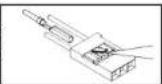
Fig. 1
- The elevator and rudder linkages at the tail end of the fuselage.
Fig. 2
- If necessary, loosen the elevator pushrod in the swivel connector mounted on the elevator servo.
Figs. 3 and 4
-
Draw the elevator pushrod back towards the tail.
-
Connect the pushrod to the elevator horn, then place the tailplane on the tail end of the fuselage.
Fig. 5
- Place the fin in position, at the same time threading the rudder pushrod into the driver below the tailplane.
Figs. 6 and 7
- Screw the tailplane and fin to the tail end of the fuselage.

Assembly and operating instructions Air Beaver ARF
No. 2569
Fig. 8
- Slip the pushrods through the swivel connectors mounted on the servos.
- Set the elevator and rudder servos to centre from the transmitter.
Set both control surfaces to centre before tightening the clamping screws in the swivel connectors.
Fig. 9
Fig. 10
Tailwheel and tailwheel linkage.
- Screw the tailwheel unit to the underside of the fuselage at the tail end.
Fig. 11
- Slip the steering wires through the steering lever, then through the swivel connectors.
- Check once more that the rudder is at centre.
- Set the tailwheel to the „straight ahead“ position, and tighten the clamping screws in the swivel connectors.
Fig. 12
- Screw the wing retainer clips to both sides of the fuselage.
Fig. 13
- This picture shows the underside of the wing.
- The two wing joiner rods are already glued in the left-hand wing panel.
- Thread the servo lead and the lighting lead through the front hole in the fuselage.
Fig. 14
-
Slide the wing into place, butting up against the fuselage; you should clearly hear both retainer clips engage. Draw the servo leads inside the fuselage at the same time.
-
Thread the landing flap pushrod through the connector barrel on the flap servo as you offer up the wing.
Fig. 15
- Push the right-hand wing (with one joiner rod) into place against the fuselage, as just described.
Fig. 16
- Don't tighten the clamping screw in the swivel connector mounted on the flap servo until you have checked the direction of rotation of the servo, and assigned a flap control at the transmitter.
Fig. 17
The main undercarriage components.
Fig. 18
- Screw the main undercarriage units to the fuselage, securing the wing struts at the same time.
Figs. 19 and 20
- Screw the wing struts to the wings.
Picture sequence 21 - 24
- Peel off the backing film from the adhesive tape on the undercarriage fairings.
- Offer up the undercarriage fairings to the wheel legs, position them carefully, and press them into place.
Fig. 25
Tailplane strakes and retaining screws
Fig. 26
- Screw the strakes to both ends of the tailplane.
Fig. 27
Propeller, spinner and fixings.
Fig. 28
- Fit the propeller, taper coilet and spinner backplate on the motor shaft, leaving about 4mm clearance between the dummy radial engine and the spinner backplate.
Fig. 29
- Fit the spinner cap and the retaining screws.
Fig. 30
Please refer to the radio control system instructions before tackling the next stage.
- Assign the control functions by connecting the servos to the appropriate sockets at the receiver.
- Connect the speed controller.
Install the receiver in the fuselage.
- Deploy the receiver aerial(s) as recommended in the RC system instructions.
- Stick two strips of Velcro tape (hook) in the battery well to secure the flight battery.
Figs. 31 and 32
- Apply a trip of Velcro tape (loop) to the underside of the flight battery.
Fig. 33
- Place the battery in the fuselage, but do not connect it at this stage.
Fig. 34
- Close the battery well cover.
Fig. 35 and 36
- The servo cover is fitted with two snap fittings. Place the cover in position and engage the latches.
- Switch the transmitter on, and move the throttle stick to the "Motor stopped" position.
- Connect the fully charged flight battery to the speed controller.

Assembly and operating instructions Air Beaver ARF
No. 2569
- Program the 'stop' and 'full-throttle' positions of the speed controller as described in the instructions on page 5.
Fig. 37, checking the working systems
Querrudrer = Ailerons
Seitenruder = Rudder
Höhenruder = Elevator
Landeklappen = Land
- Check the neutral position of the control surfaces.
- If necessary, adjust the position of the rudder and elevator push-rods in the swivel pushrod connectors, and only then tighten the M3 x 3 clamping grubscrews in the connectors.
- Fine corrections to the allerons and flaps can be carried out at the transmitter.
- Stand behind the model.
- Check the direction of rotation of the servos:
- Move the aileron stick to the right, and the right-hand aileron should rise, the left-hand aileron fall.
- Pull the elevator stick back towards you, and the trailing edge of the elevator should rise.
- Move the rudder stick to the right, and the rudder should deflect to the right.
- If any function operates in the wrong 'sense', correct it using your transmitter's servo reverse facility for that function.
- Set the control surface travels as stated in the drawings.
Adjusting the landing flaps
- Check the direction of rotation of the landing flap servo, then tighten the clamping screw.
up: 0 mm
down: 25 mm
- We recommend setting up a mixer to apply 5mm down-elevator to prevent the model ballooning up when the flaps are lowered.
- The travels are measured at the inboard end of the control surfaces.
- The stated control throws are just a guide for the first few flights. You will probably need to adjust the settings to suit your individual flying style.
- The Expo settings should also be adjusted to suit the pilot's preference.
rohbe Modelispart
Fig. 38
Checking the power system
-
Hold the model in such a way that the propeller is free to rotate. Caution: Whenever you are working on the power system (for installation, set-up or maintenance), keep well clear of the rotational plane of the propeller - injury hazard.
-
Check the direction of rotation of the motor. The propeller must turn anti-clockwise when viewed from the front.
- If this is not the case, swap over any two of the three wires between the motor and the speed controller.
- First disconnect the flight battery from the speed controller, then switch the transmitter off.
Fig. 39, balancing
- Mark the Centre of Gravity - .C.G." on both sides of the fuselage at a point 60~mm from the wing leading edge. Support the model at the marked points and allow it to hang freely. Ideally the model will now balance level, with the nose inclined slightly down.
- Adjust the position of the flight battery if necessary.
- Mark the battery location in the fuselage, so that you can be confident of replacing it in the same position after removing it.
Fig. 40, lighting system
- Locate the two-pin plug attached to the lighting unit, and connect it to a vacant receiver channel, taking care to maintain correct polarity. Caution: the signal pin is not used.
- The lighting system (navigation lights and landing light) are permanently on when the receiving system is operating, and cannot be controlled from the transmitter. If you prefer to fly without the lights, disconnect the plug at the receiver.
- The lighting system uses LEDs, whose minimal current drain has no effect on flight times.
Test-lying, flying notes
- Read the sections in the Safety Notes entitled "Routine preflight checks" and "Flying the model" before attempting to fly the model for the first time.
- For your first few flights please wait for a day with no more than a gentle breeze.
-
A good flying site consists of a large, flat, open grassy field, devoid of trees, fences, high-tension overhead cables etc.
-
Repeat the check of all the working systems.
- The model is capable of taking off from a hard surface as well as being hand-launched.
- The model must always be launched directly into any wind.
- If a suitably smooth runway is available, we recommend a ground take-off.
- Carry out a series of taxi tests to become accustomed to the model's ground handling and response to the control surfaces.
- With the nose pointing straight into wind, apply full-throttle and allow the Beaver to pick up speed. When flying speed is reached, lift off with a brief application of up-elevator.
- Ask an experienced modelling friend to hand launch the aircraft for you. He should be capable of giving the model a reasonably strong, flat launch.
- With the motor running at full-throttle, give the aeroplane a firm launch directly into any breeze, with the fuselage and wings level.
- Keep the Beaver flying straight and level at first; don't initiate a turn while it is still close to the ground.
- Adjust the control surface trims if necessary, so that the model flies straight with a reasonable rate of climb "hands off".
- Check the model's response to control commands. You may need to increase or reduce the control surface travels after the first landing.
- Check the aeroplane's stalling speed at a safe height.
- Check the effect of the landing flaps at a safe altitude, with the motor throttled back or switched off. Don't deploy the flaps close to the ground until you are confident of the model's reaction.
- Keep the aeroplane's speed well above the stall for the landing approach.
- If you needed to adjust the trims during the test-flight, correct the length of the appropriate pushrod once the model is back on the ground, then return the transmitter trims to centre so that full trim travel is available to both sides of neutral for subsequent flights.
- After every flight check that the wings are still securely attached to the fuselage; re-engage the retaining clips if necessary.
We reserve the right to alter technical specifications.
robbe
Operating Instructions
Air Beaver Power Set
No.
2569
Specification, 40 A speed controller:
Continuous current: 40 A
Peak current: 55 A (max. 10 sec.)
BEC mode:
BEC output: 5 V/3 A
LiPo cell count: 2 - 3
NIMH cell count: 5 - 9
Low-voltage protection: yes
Dimensions (Speed controller): 68 x 25 x 8 mm
Weight: 35g
Specification, BL outrunner:
Operating voltage: 11.1 V (3S LIPO)
Max. load current: 28 A
No-load speed: 850 RPM/V
Dimensions.DxL:41x33.4mm
Shaft diameter: 4 mm
Weight: 120 g
Connect the flight battery to the speed controller; you will hear the special sound sequence, 123, followed by a fairly long beep and the selected brake setting.
The speed controller is now ready for use.
Protective functions
-
Start-up guard: if the motor does not start within two seconds of the throttle command, the speed controller switches off the output voltage. If this should happen, you MUST move the throttle stick fully back in order to start the motor. Failure to start may have the following reasons: the connection between speed controller and motor is intermittent, the propeller or motor is jammed, the gearbox is damaged, etc.
-
Overheating guard: if the controller's temperature rises above 110^ , the unit reduces the output voltage. 3. Throttle signal failure guard: if the throttle signal is absent for one second, the controller reduces the output voltage. If a further failure occurs for two seconds, the controller switches off the output voltage completely.
Caution: this controller is not protected against reversed polarity. Connecting a battery to the controller's terminals with reversed polarity will instantly ruin the unit.
If you prefer to use a separate receiver battery instead of the BEC system, you must withdraw the red wire from the receiver lead attached to the controller, and insulate the bare ends to avoid short-circuits.
VERY IMPORTANT: since different transmitters feature different throttle settings, we strongly advise you to use the „Throttle range set-up function" to calibrate the throttle range.
Setting the full-throttle and stop positions:
(If the transmitter is new, the throttle range should always be calibrated)
Switch transmitter on, move throttle stick to full-throttle position.
Connect battery to speed controller.
You will hear the special beep sequence 123^ This means that the battery voltage is in the green zone.
This is followed by two fairly long beeps which confirm that the controller has correctly read in the upper limit of the throttle range.
The throttle stick must now be moved to the appropriate Stop position within two seconds. The controller confirms this with a fairly long beep.
This calibration procedure is concluded with the audible signal which indicates the brake setting (1 x short beep = brake off; 2 x short beep = brake on).
The speed controller is now ready for use.
Brake setting:
Switch transmitter on, move throttle stick to full-throttle position.
Connect battery to speed controller
You will now hear two fairly long beeps indicating the full-throttle position.
After about two seconds the controller emits one brief beep to indicate the .Brake off setting.
After a further two seconds you will hear two brief beeps indicating Brake on
If you wish to set Brake off, you must move the throttle stick to the zero position after the first brief beep. If you wish to activate the brake, wait until you hear the second series of beeps before moving the stick.
To confirm the brake setting you will now hear a single fairly long beep followed by your selected setting (1 or 2 brief boeps).
The speed controller is now ready for use.
NOTE:
If you do not move the throttle stick during the set-up phase, the motor will then not run. In this case you must repeat the procedure.
Using the controller for the first time:
- Move the throttle stick to the Stop position, then switch the transmitter on.
robbe
Operating Instructions
Air Beaver Power Set
No.
2569
Warning beeps, fault-finding
Fault Possible cause Solution
The motor does not start Inadequate connection Check power connections, after switching on; no beeps between battery and controller replace plugs / sockets
The motor does not start Input voltage too high or Check battery voltage after switching on; warning too low sequence "beep-beep, beep beep, beep beep," (pause between "beep-beeps" approx. one second)
The motor does not start Invalid throttle signal Check receiver and / or after switching on; warning transmitter sequence "beep-beep-beep" Check throttle lead (pause between the beeps) approx. two seconds
The motor does not start Throttle stick not at Move throttle stick after switching on; warning bottom end-point fully back sequence "beep-beep-beep." (pause between the "beeps" approx. one quarter-second)
The motor does not start. Throttle channel reversed. Reverse throttle channel after switching on; special sequence "56712" after two beeps (beep-, boep-)
The motor runs in reverse Incorrect connection between Swap over any two wires speed controller and motor between controller and motor motor
The motor stops when running
Throttle signal failure
Check receiver /
Controller in low-voltage guard mode
Land model immediately recharge battery
Unreliable connections Check all electrical con
connections, battery connectors, throttle charr

Safety notes
lead, motor wires
Always keep to the standard power-on sequence: switch the transmitter on first, and only when then the receiver. Reverse the sequence when switching off.
- Keep within the values stated in the Specifications.
Observe correct polarity in all wiring
Take great care to avoid short-circuits.
Install / protect the speed controller in such a way that it cannot come into contact with grease, oil or water.
Provide adequate ventilation.
- Keep well clear of the rotational plane of the propeller whenever the battery is connected - injury hazard.
Guarantee
Naturally we guarantee this battery charger for the statutory period of 24 months. If you believe you have a valid claim under guarantee, please contact your dealer in the first instance, as he is responsible for processing guarantee claims.
During the guarantee period we will correct any operating deficiencies, production defects and material faults which arise, at no charge to you. We will not entertain any claims beyond these terms, e.g. consequent damage.
The unit must be returned to us carriage-paid; it will also be returned to you carriage-paid. We will not accept goods sent to us without pre-paid carriage.
We accept no liability for transit damage and the loss of your shipment; we therefore recommend that you take out suitable insurance to cover these risks.
Send the unit to the Service Centre responsible for the country in which you live.
The following conditions must be fulfilled if we are to process your guarantee claim:
- Send proof of purchase (till receipt) with your shipment.
The unit must have been operated in accordance with the operating instructions.
The unit must have been operated with the recommended power sources and genuine robbe accessories.
- The unit must not exhibit damage due to damp, unauthorised intervention, reverse polarity, overload conditions or mechanical damage.
- Please include a concise description of the fault or defect, as this will help us identify the problem.
Liability exclusion
robbe Modellport accepts no liability of any kind if the ESC is used for any purpose other than that stated. We at robbe Modellport are unable to ensure that you observe the instructions supplied with the ESC and we have no control over the methods you employ for using, operating and maintaining the device and the batteries. For this reason we are obliged to deny all liability for loss, damage or costs which are incurred due to the incompetent or incorrect use and operation of our products, or which are connected with such operation in any way. Unless otherwise prescribed by law, our obligation to pay compensation, regardless of the legal argument employed, is limited to the invoice value of those robbe products which were immediately and directly involved in the event in which the damage occurred. This does not apply if the company is found to be subject to unlimited liability according to binding legal regulation on account of deliberate or gross negligence.

Assembly and operating instructions Air Beaver ARF
No. 2569
Service Centre Addresses
| Land Firma Strasse Stadt Telefon Fax E-Mail |
| Andorra | Sorleney | Santa Anna, 13 | AND-00130 Les escaides- Princip. D'Andorre | 00376-862 865 | 00376-825 476 | sorteny@sorteny.com |
| Dänemark | Nordic Hobby A/S | Bogensevej 13 | DK-8940 Randers SV | 0045-86-43 61 00 | 0045-86-43 77 44 | hobby@nordichobby.com |
| Deutschland | robe-Service | Metzloser Str. 38 | D-36355 Grebenhain | 0049-6644-87-777 | 0049-6644-87-779 | hotline@robbe.com |
| England | robe-Schüller UK | LE10-UB | GB-LE10 3DS Leicestershire | 0044-1455-637151 | 0044-1455-635151 | keith@robbeuk.co.uk |
| Frankreich | S.A.V. Messe | 6, Rue Usson du Poitou, BP 12 | F-57730 Folschwiller | 0033 3 87 94 62 58 | 0033-3-87 94 62 58 | sav-robe@wanadoo.fr |
| Griechenland | TAG Models Hellas | 18,Vriuilon Str. | GR-14341 New Philadelphia/Athen | 0030-2-102584380 | 0030-2-102533533 | info@tagmodels.gr |
| Italien | MC-Electronic | Via del Progresso, 25 | I-36010 Cavazzale di Monticello C.Otto (Vi) | 0039 0444 945992 | 0039 0444 945991 | mcelec@libero.it |
| Niederlande/Belg. | Jan van Mouwerik | Slot de Houvelaan 30 | NL-3155 Maasland | 0031-10-59 13 594 | 0031-10-59 13 594 | van Mouwerik@versatel.nl |
| Norwegen | Norwegian Modellers | Box 2140 | N-3103 Toensberg | 0047-333 78 000 | 0047-333 78 001 | per@modellers.com |
| Österreich | robe-Service | Puchgasse 1 | A-1220 Wien | 0043-1259-66-52 | 0043-1258-11-79 | office@robe.at |
| Schweden | Minicars Hobby A.B. | Bergsbrunnagatan 18 | S-75323 Uppsala | 0046-186 06 571 | 0046-186 06 579 | info@minicars.se |
| Schweiz | robe Futaba Service | Hinterer Schürmtweg 25 | CH-4203 Grellingen | 0041-61-741 23 22 | 0041-61-741 23 34 | info@robbefutaba-service.ch |
| Slowakische Rep. | Ivo Marhoun | Horova 9 | CZ-35201 AS | 00420 351 120 162 | | ivm2000@seznam.cz |
| Spanien | robe-Service | Metzloser Str. 38 | D-36355 Grobenhain | 0049-6644-87-777 | 0049-6644-87-779 | hotline@robbe.com |
| Tschech. Rep. | Ivo Marhoun | Horova 9 | CZ-35201 AS | 00420 351 120 162 | | ivm2000@seznam.cz |
robe Modellsport GmbH & Co. KG hereby declares that this product satisfies the fundamental requirements and other relevant regulations contained in the appropriate CE directives. The original Conformity Declaration can be viewed on the Internet under www.robbe.com: click on the logo button marked "Conform" which is included in each device description.

This symbol means that you must dispose of electrical and electronic equipment separately from the general household waste when it reaches the end of its useful life.
Take your equipment to your local waste collection point or recycling centre. This applies to all countries of the European Union, and to other European countries with a separate waste collection system.
Errors and omissions excepted. Modifications reserved.
Copyright robbe-Modellspor 2012
Copyrighting and re-printing, in whole or in part, only with prior written approval of robbe-Modellssport
GmbH & Co. KG

Courant permanent: 40 A
Courant de pointe: 55 A (max. 10 s)
Mode BEC: linéaire
Sortie BEC: 5 volts / 3 A
Nbre d'elements Li-Bo: 2 a 3
Characteristicas techniques
Envergadura: aprox. 1520 mm
Longitud total: aprox. 960 mm Superficial alar total: aprox. 283
N^2 Ref. Pieza
25690007 Unased vrtule
25690008 Atrapa motoru
25690009 Viko baterle
25690010 Stifdavymotor upevnénfm
25690011 Stfidavy regulator 40A ESC
Obr.1