NanoVector - Remote control toy ROBBE - Free user manual and instructions
Find the device manual for free NanoVector ROBBE in PDF.

| Product type | Radio-controlled toy - Electric glider (NanoVector ARF) |
| Brand | ROBBE |
| Model | NanoVector (ref. 2580) |
| Dimensions | Total length: approx. 510 mm; Wing area: approx. 10 dm² |
| Weight | Approx. 350 g (ready to fly) |
| Wing loading | Approx. 35 g/dm² |
| Motor power supply | LiPo battery 3S 1000 mAh (recommended); Brushless outrunner motor (voltage 11.1 V) |
| Speed controller | Brushless 30 A (linear BEC 5V/2A); overheat and signal loss protection |
| Required radio control | Minimum 4 channels with delta mixing (recommended 2.4 GHz) |
| Installed servos | 2x robbe E-COLINE BG (mounted for combined aileron/elevator) |
| Propulsion | Integrated 50 mm ducted fan |
| Main functions | Straight flight, turns, climb/descent; delta mixing for ailerons and elevator |
| Maintenance and cleaning | Clean with a dry cloth; check condition of connectors and cables |
| Safety | Startup sequence: transmitter first, then battery; polarity reversal destroys the speed controller |
| Spare parts and repairability | Available parts: ducted fan (ref. 25800001), BL motor (25800002), speed controller (8629), servo (26000001), canopy (25800003) |
| General information | Detailed manual included; legal warranty 24 months; technical modifications reserved |
Frequently Asked Questions - NanoVector ROBBE
User questions about NanoVector ROBBE
0 question about this device. Answer the ones you know or ask your own.
Ask a new question about this device
Download the instructions for your Remote control toy in PDF format for free! Find your manual NanoVector - ROBBE and take your electronic device back in hand. On this page are published all the documents necessary for the use of your device. NanoVector by ROBBE.
USER MANUAL NanoVector ROBBE
Assembly and operating instructions
Notice de montage et de pilotage Istruzioni di montaggio e d'uso
Assembly and operating instructions Nano-Vector ARF
No. 2580
Specification
Wingspan: approx. 580 mm
Overall length: approx. 510 mm
Total surface area: approx. 10 dm²
All rights reserved. ©253
All-up weight: approx. 350 g
Total surface area loading: approx. 35g / dm^2
Dear Customer,
Congratulations on your choice of a factory-assembled model aircraft from the robbe Modellsport range. Many thanks for placing your trust in us.
The model can very quickly be completed ready to fly. Please read right through these instructions and the separate information sheets before attempting to assemble and fly the model, as this will make it much easier to complete the tasks required.
We constantly strive to update our products to reflect the latest developments. You can find details of technical Improvements and revised documentation on the Internet by calling up the appropriate product description at our website: www.robbe.com.
All directions, such as "right-hand", are as seen from the tail of the model, looking forward.
Notes on the power system
A brushless outrunner motor and Impeller (duced fan) are already installed in the fuselage.
The motor is connected to the speed controller, ready for use. To complete the power system all you have to do is connect the LiPo flight battery.
Instructions for setting up the speed controller are included in the Appendix to the Instructions.
The radio control system
For this model you require a radio control system with at least four channels and a delta mixer. We particularly recommend 2.4 GHz systems.
The servos for the combined alerons / elevators are already installed.
The receiving system is powered by the speed controller's integral BEC system.
robbie Modellsport
Before you check the model's working systems, set the control surface servos to neutral from the transmitter (transmitter sticks and trims central).
Before flying the model always move the throttle stick to the "motor stopped" position before switching the transmitter on. Only then connect the flight battery.
To switch off, first disconnect the flight pack from the speed controller, and only then switch the transmitter off.
When installing or setting up the receiving system components, including the speed controller, be sure to read and observe the instructions supplied with them.
You should also read right through the instructions and safety information supplied with the battery pack and charger before using these items for the first time.
Joining the components, recommended adhesives
All parts must be trial-fitted "dry" (without glue) before you reach for the glue.
robbe Speed 1 No.5062
Activator spray No. 5020
Please take great care to avoid excess adhesive running onto the painted surfaces, as this will damage the finish.
Recommended accessories
Description Order No.
T-6 EX-R6308SBT 2.4 GHz
radio control system F 4106
Transmitter battery 8NIMH 2000 4548
ROXXY® POWER ZY 3S 1000mAh 30C 6911 or
2x ROXXY® POWER ZY 2S 1000mAh 30C 6910 wired in series
Connector for battery 8895
Heat-shrink tubing 4.8 D 5151
Battery charger, e.g.
POWER PEAK@ Uni 7 EQ,230V
Transmitter battery charge lead
Battery charge lead Velcro (hook-and-loop) tape
8564
F1415
8881
1713
Kit contents
Ready-made EPO foam parts set, with decals already applied (fuselage / wing, motor cover, canopy and cockpit)
- Separate EPO foam fins and fuselage nose-cone
Control surface linkage hardware pack
Factory-flitted 50 mm Ø ducted fan unit
Factory-fitted brushless motor and speed controller
- 2x factory-installed robbe E-COLINE 8G servos
- Multi-lingual assembly instructions
Replacement parts list
Order No. Description
25800001 Ducted fan unit 50 mm Ø
25800002 Brushless motor
25800003 Cabin
26000001 E-COLINE Servo 8G
8629 BL controller ROXXY® Control 930
Figs. 1 and 2
- Glue the fins in place, lining them up accurately
Figs. 3 and 4
- Glue the nosecone to the fuselage.
Fig. 5
- Installing the receiver: connect the servos and the speed controller to the receiver, referring to the RC system instructions for the correct channel assignment and connector pin configuration. (the orange signal wire corresponds to the white wire used for robbe-Futaba systems).
- Place the receiver in the fuselage and deploy the receiver aerial(s).
Fig. 6
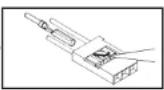
- Slide some heat shrink pieces onto each battery lead. Solder the socket according to figure and insulate the solder joint with heat shrink tubing.
Important: Do not reverse the connections of the battery to the speed controller. Reversing the polarity will destroy the controller immediately.
Fig. 7 and 8
Sender = Transmitter
ON = ON
Motor aus = Motor stopped

Assembly and operating instructions Nano-Vector ARF
No. 2580
- Charge the flight battery.
- Switch the transmitter on, and move the throttle stick to the "motor stopped" end-point.
- Give the flight battery a full charge, apply Velcro (hook-and-loop) tape to the pack, place it in the fuselage, and connect it. Wait for the speed controller to emit a series of beeps.
- Place the canopy on the fuselage; it is held in place by a magnet at one end and a locating tongue at the other.
Figs. 9 and 10
Querrudr = Aileron
rechts = right
Hohenruder = Elevator
- Activate the delta mixer at the transmitter.
- Check the channel assignment of the control surfaces, and swap over the connectors at the receiver if necessary.
- Check the neutral position of the control surfaces. If any surface is not exactly at centre, loosen the screw in the appropriate swivel pushrod connector, move the panel to "neutral", then tighten the screw again.
- Check the direction of rotation of the servos.
- When you move the aileron stick to the right (a), the right-hand aileron (a) should rise, the left-hand aileron (b) fall.
- Pull the elevator stick back towards you (c), and the rear edges of the allerons rise.
If either control surface function works the wrong way round correct it using your transmitter's servo reverse facility for that function.
- Check that all the linkages are firmly fixed, but free-moving. Check in particular that the nuts securing the swivel pushrod connectors are tight enough.
- The travels are measured at the inboard end of the control surfaces.
- The stated control throws are just a guide for the first few flights.
The exact settings will need to be adjusted to suit the individual pilot's flying style.
- The Expo settings should also be adjusted to suit the pilot's preference.
robbeb Modellsport
Fig. 11
Checking the power system
Motor "aus" = Motor "off"
Hold the model securely. Check that there are no loose objects, such as rags, tools or similar, in front of the model, as they could be sucked into the fan unit.
- Move the throttle stick forward. The motor should now run, and you should be able to feel a distinct flow of air coming from the tail end of the fuselage.
- Move the throttle stick back to the "motor stopped" position.
- First disconnect the battery from the speed controller, then switch the transmitter off.
Fig. 12
- Place the battery in the model for balancing; do not connect it.
- Mark the Centre of Gravity on both sides of the fuselage, as shown in the view of the underside.
Support the model at the marked points, and allow it to hang freely. The CG is correct when the model balances level, with the nose inclined slightly down. - Adjust the position of the flight battery if necessary.
- Mark the battery location in the fuselage, so that you can be confident of replacing it in the same position after removing it.
- With the battery in the correct position, pack pieces of scrap foam round it, so that it cannot shift in flight and alter the model's balance.
The model is ready for flying once you have recharged the battery.
Test-flying, flying notes
Read the sections in the Safety Notes entitled "Routine preflight checks" and "Flying the model" before attempting to fly the model for the first time.
- For your first few flights please wait for a day with no more than a gentle breeze.
-
A good flying site consists of a large, flat, open grassy field, devoid of trees, fences, high-tension overhead cables etc.
-
Repeat the check of all the working systems.
- Ask an experienced modelling friend to hand-launch the aircraft for you. He should be capable of giving the model a reasonably strong, flat launch.
- The model must be launched directly into any wind.
- With the motor running at full-throttle, give the aeroplane a firm
launch directly into any breeze, with the fuselage and wings level. - Keep the Nano-Vector ARF flying straight and level at first; don't turn the model while it is still close to the ground.
- Adjust the control surface trims if necessary, so that the machine files straight with a reasonable rate of climb "hands off".
- Check the model's response to control commands; you may need to increase or reduce the control surface travels after the first landing.
- Check the aeroplane's stalling speed at a safe height.
- Keep the model's speed well above the stall for the landing approach.
- Always switch the motor off before the model touches down, to avoid dirt and grit damaging the fan.
If you needed to adjust the trims during the test flight, correct the length of the appropriate pushrod once the model is back on the ground, then return the transmitter trims to centre so that full trim travel is available to both sides of neutral for subsequent flights.
Fig 13, access to the fan unit and speed controller
- The ducted fan unit is accessible from underneath for maintenance or repair work.
This is the method of opening the fuselage:
- The fuselage hatch is held in place by magnets. Open the hatch by pressing from the inside.
- Remove the fuselage hatch.
- Disconnect the electrical plugs and sockets, and the speed controller or fan unit can be removed from the fuselage. Write down the colours of the mating wires.
- Reverse the procedure to re-install the parts.
We reserve the right to alter technical specifications.

Operating instructions
Nano-Vector ARF Power Set
No.
2580
Please read right through these operating instructions before attempting to use the speed controller for the first time.
Specification, BL-ESC 30 A controller:
Continuous current: 30 A
Peak current: 40 A (<10 sec.)
BEC mode: linear
BEC output: 5V / 2A
Cell-count, LiPo: 2 - 4
Cell-count, NiMH / NC: 5-12
Low-voltage guard: yes
Dimensions (controller): 23 × 43 × 6 mm
Weight: 25 g
Caution: the speed controller is not protected against reversed polarity! Connecting the battery to the controller with reversed polarity will instantly ruin the controller.
If you wish to use a separate receiver battery instead of the BEC system, locate the receiver connector attached to the speed controller, withdraw the contact on the red wire, and insulate the bare end to avoid short-circuits.
VERY IMPORTANT: since different transmitters feature different throttle channel values, we urgently recommend that you use the "throttle range set-up function" to set the throttle range. Please read the section entitled "Setting the full-throttle and stop positions" later in these instructions.
Using the speed controller for the first time:
Pull the throttle stick fully back (towards you), then switch the transmitter on. Connect the flight battery to the speed controller.
You will hear one of the following sequences, depending on the battery type:
LiPo: the controller emits two audio sequences:
-
**** if a 3S LiPo pack is detected. The cell-count is automatically detected (the number of beeps indicates the number of cells).
-
"if the brake is switched on.
*** if the brake is switched off.
NiMH / NC: the controller emits one audio sequence:
In this case you will hear only "or" to indicate brake switched on or off.
The speed controller is ready for use.
Move the throttle stick forward: motor starts.
Setting the full-throttle and stop positions (if the transmitter is new, the throttle range should always be re-set):
Switch the transmitter on, and move the throttle stick fully forward (away from you).
Connect the flight battery to the speed controller.
The controller emits the sequence ".-". Move the throttle stick to the desired Stop position within the period of the four repeated beeps.
The controller emits "--" to indicate it has registered the Stop position. It now emits the audio sequence according to the battery type. The speed controller is ready for use.
Protective functions
- Overheating guard: if the temperature of the speed controller rises above 110^ , the unit reduces the output voltage.
- Throttle signal failure guard: if the throttle signal is absent for a period of one second, the speed controller reduces the output voltage. If the signal fails again for a period of two seconds, the speed controller switches off the output voltage completely.
Description of function
1. Full-throttle / Stop position
- Brake setting: brake ON / brake OFF; default setting = brake OFF
- Battery type: Li-xx (Li-Ion or Li-Poly) / Ni-xx (NiMH or NC); default setting: Li-xx.
- Low-voltage cut-off: low / medium / high; default setting: medium
1) In the case of Li-xx batteries the cell-count is detected automatically. Cut-off voltage low / medium high at:
2.8 V / 3.0 V / 3.2 V. E.g.: medium cut-off voltage setting with three LiPo cells: cut-off voltage is 3 × 3 = 9V .
2) NiMH / NC batteries: cut-off voltage low / medium / high at: 50% / 60% / 65% of the initial voltage. E.g: with a six-cell NiMH battery the fully-charged voltage is 1.44 × 6 = 8.64V ; if the cut-off voltage is set to low, the cut-off voltage is: 8.64 × 50% = 4.32V . - Default setting: resets the values to the default settings (see Programming).
- Timing: automatic / low / high; default setting = automatic
Automatic timing can safely be selected for most motors. For high performance we recommend low timing for two-pole motors (inrunners) and high timing for motors with six or more poles.
Carry out a bench check before flying the model. - Start-up / Power-on mode: ultra-soft / soft / normal; default setting = soft Normal is suitable for fixed-wing model aircraft.
The start-up speed when set to soft / ultra-soft is fairly slow: one second (soft start), 1.5 seconds (ultra-soft start), timed from start-up to full-throttle. The ultra-soft setting is particularly useful for models with geared motors.
8.RPM Control, Heli Mode
Default setting: off
Selecting Governor mode disables the brake. The low-voltage cut-off is set to reduced power. - Direction of motor rotation: the direction of rotation of the motor can be reversed electronically (see Programming).

Operating instructions
Nano-Vector ARF Power Set
No.
2580
- Switchable pulse frequency, 8 kHz / 16 kHz; default setting: 8 kHz
8 kHz: pulse frequency for two-pole motors, e.g. inrunners
16 kHz: pulse frequency for motors with more than two poles, e.g. outrunners.
- Low-voltage cut-off mode; default setting: soft
Soft: reduced power
Hard: complete cut-off
Programming
- Switch the transmitter on and move the throttle stick fully forward. Connect the flight battery to the speed controller (ESC).
- After five seconds you will hear the first audio sequence of programming mode. If you leave the throttle stick at the full-throttle position, the controller generates various audio sequences indicating the user-variable parameters - see table below.
- The audio sequence for each individual parameter is repeated four times. If you wish to change a particular parameter, move the throttle stick to the Stop position within the period of the four repetitions. After this the controller emits an audio sequence according to the set battery type (see "Using the speed controller for the first time").
Note: every time you change a parameter, disconnect the speed controller from the battery
for about five seconds; this causes the unit to store the new setting.
ou can only change one parameter during each programming process.
Audio sequences in programming mode
Audio sequences Controller functions
| 1 Full-throttle / Stop position | |
| ... | ... |
| 2 Brake | |
| ... | ... |
| 3 Brake on / off | |
| ~, ~, ~, ~ NiMH / NC | |
| ~, ~, ~, ~, ~ LiPo | |
| 4 Low-voltage cut-off | |
| * - , * - , * - Low: 2.8 V / 50% | |
| * - , * - , * - Medium : 3.0 V / 60% | |
| * - , * - , * - High: 3.2 V / 60% | |
| 5 Reset to default settings | |
| - , - , - Reset | |
| 6 Timing | |
| - , - , - Automatic (7 - 30°) | |
| - , - , - Low (7 - 22°) | |
| - , - , - High (23 - 30°) | |
| 7 Start-up / Power-on mode | |
| v, v, v, w | Ultra-soft |
| v, v, v, v | Soft |
| v, v, v, v, v, v | Normal |
robbb Modelsoort
8 Helicopter mode
| Speed governor mode off | |
| Soft-start, 5 sec. delay | |
| Soft-start, 15 sec. delay | |
| 9 Motor direction | |
| W. W. W. W | Right / Left |
| 10 Pulse frequency | |
| //, //, //, // | 8 kHz |
| //, //, //, // | 16 kHz |
| 11 Low-voltage / Cut-off mode | |
| ----,----,----,---- | Reduced power |
| ----,----,----,---- | Full cut-off |
Safety notes
Keep to the correct sequence when switching on: always switch the transmitter on first, followed by the receiver. Reverse the sequence when switching off.
Do not exceed the values stated in the Specification.
Take care to maintain correct polarity in all wiring.
It is essential to avoid short-circuits.
- Install and protect the speed controller in such a way that it cannot come into contact with grease, oil or water.
- Provide adequate air circulation for cooling
- Keep well clear of the rotational plane of the propeller when the battery is connected - injury hazard.
Guarantee
Naturally we guarantee this speed controller for the statutory period of 24 months. If you believe you have a valid claim under guarantee, please contact your dealer in the first instance, as he is responsible for processing guarantee claims. During the guarantee period we will correct any operating deficiencies, production defects and material faults which arise, at no charge to you. We will not entertain any claims beyond these terms, e.g. consequent damage.
The unit must be returned to us carriage-paid; it will also be returned to you carriage-paid. We will not accept goods sent to us without pre-paid carriage.
We accept no liability for transit damage and the loss of your shipment; we therefore recommend that you take out suitable insurance to cover these risks.
Send the unit to the Service Centre responsible for the country in which you live.
The following conditions must be fulfilled if we are to process your guarantee claim:
- Send proof of purchase (till receipt) with your shipment
The unit must have been operated in accordance with the operating instructions.
- The unit must have been operated with the recommended power sources and genuine robbe accessories.
- The unit must not exhibit damage due to damp, unauthorised intervention, reverse polarity, overload conditions or mechanical damage.
- Please include a concise description of the fault or defect, as this will help us identify the problem.

Operating instructions
Nano-Vector ARF Power Set
No.
2580
| Table 1. Motor and controller characteristics | ||
| Audible warnings, fault-finding Error Possible reason Solution | ||
| Motor does not run; however audible beeps when switching on. i.e. the controller attempts to detect the cell-count automatically. | Speed controller's throttle function not calibrated. | Calibrate speed controller throttle function |
| Motor does not run, no audible beeps when switched on. Servos do not function. No power. Fit a fully charged battery. Faulty soldering (dry joints). Re-solder dry joints. Reversed polarity battery lead. Check and correct lead. Speed controller fault. Replace controller | Intermittent / loose connection between battery and speed controller. Reversed polarity connection between speed controller and receiver (throttle lead). | Clean / replace plug and socket. Check speed controller lead, correct contacts if necessary. |
| Motor does not run, no audible beeps when switched on. BUT: servos function. Burned out motor windings Faulty soldering (dry joints). Re-solder dry joints. | Intermittent / loose connection between battery and speed controller. Replace motor. | Clean / replace plug and socket. |
| When the controller is switched on the motor does not run. Two beeps, followed by brief pause (* * * * *). | Battery voltage outside the permissible range. | Replace battery with a fully charged pack. Check battery voltage. |
| When the controller is switched on the motor does not run. Single beep, followed by brief pause (* * * *). | The speed controller has not detected a normal throttle signal from the receiver. actually present (connect servo o check throttle channel). | Check whether the speed controller lead is connected to the receiver throttle channel. Check transmitter and receiver to determine whether a throttle signal actually present (connect servo o check throttle channel). |
| When the controller is switched on the motor does not run. Constant beeps (* * * *). | Throttle stick not at bottom end-point when the transmitter was switched on. | Move the throttle stick to the "fully back" position. |
| When the controller is switched on the motor does not run. Two long beeps, followed by two brief beeps (* *). | Throttle channel reversed; therefore controller has switched to Programming mode. | Select servo reverse menu at transmitter, reverse throttle channel. Note: Futaba system - must be set to "Reverse". |
| Motor runs in wrong direction. Motor stops in flight. | Reversed cables between speed controller and motor. model; alternatively change the default parameters. | Swap over any two of the three wires between the speed controller and the motor, or select "Motor direction reverse" function (controller's programming) |
| No throttle signal. | Check whether RC system is working properly. controller lead: there must be adequate space between these units in order to avoid interference. Fit ferrite ring in speed controller's throttle lead. | Check position of controller and receiver. Check position of receiver aerial and land model immediately, replace battery. |
| Possible defective cable connection. | Battery voltage fallen to low voltage threshold. Check cables for possible damage. | |
| Motor starts unexpectedly; controller overheats. Inadequate cooling. | Possible interference at the flying field. site. Switch speed controller on again, andcheck if it works properly. If the problem cannot be solved, check the speedcontroller at a different flying site. | Normal operation of the speed controller can be affected by interference at the |
| Re-position controller to ensure sufficient cooling. | ||
| Servos drawing too muchcurrent; controller overloaded. REC current must not exceed the value stated in the Specification. | Fit smaller servos whichdo not overload the speedcontroller. The maximum | |
| Motor or propeller too large. | Fit a smaller motor or a smaller propeller. | |

This symbol means that you must dispose of electrical and electronic equipment separately from the general household waste when it reaches the end of its useful life. Take your apparatus to your local waste collection point or recycling centre. This applies to all countries of the European Union, and to other European countries with a separate waste collection system.
Service
The address of the Service company responsible for your country can be found on the Internet: www.robbe.com
robbo Modellsof GmbH & Co. KG horeby declares that this product satisfies the fundamental requirements and other relevant regulations contained in the appropriate EU directives. The original Contfortometry Declaration can be viewed on the Internet under www.robbo.com: click on the logo button marked "Conform" which is included in each docvo description.
We accept no liability for errors and technical modifications. Copyright robbe Modellreport 2012. This document may not be copied or reproduced in whole or in part without the prior written approval of robbe Modellreport GmbH & Co. KG

envergure:approx.580 m
T6EX-R6308SBT 2.4 GHz FASST F4106
| w, w, w, w | Super couple |
| v, v, v, v | Souple |
| vv, vv, vvv, vvv | Normal |
oppure connettere in series
2x ROXXY® POWER ZY 2S 1000mAh 30C 6910
Characteristicas techniques, BL-Outrunner:
| ~, ~, ~, ~ | NiMH / NC |
| ~~,~~,~~,~~,~~,LiPo |
Regulator Nano-Vector ARF
Cis.
2580
Pfred uvedenim regulaor do provozu si prosim peclive prectete tento provozni navod.
Regulator Nano-Vector ARF
Cis.
2580