Kit DogFighter - Remote control toy MULTIPLEX - Free user manual and instructions
Find the device manual for free Kit DogFighter MULTIPLEX in PDF.

| Product type | Radio-controlled airplane kit |
| Brand | MULTIPLEX |
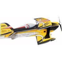
| Model | DogFighter |
| Category | Radio-controlled toy / Model airplane |
| Wingspan | 882 mm |
| Overall length | 812 mm |
| Flying weight | Approx. 850 g |
| Wing area | 19.07 dm² |
| RC functions | Elevator, rudder, ailerons, motor (rudder optional) |
| Propulsion | Brushless motor (Tuning or Ultra Speed kit) |
| Recommended speed controller | MULTIcont BL-40 S-BEC (RR version) |
| Recommended battery type | LiPo 3S 2200 mAh (Li-BATT FX 3/1-2200) |
| Material | ELAPOR® foam |
| Assembly | Kit to assemble, requires cyanoacrylate glue |
| Recommended glue | Zacki-ELAPOR® or medium viscosity cyanoacrylate glue |
| Spare parts | Available, full list in the manual |
| Safety | Check motor/propeller mountings before flight; do not fly towards people or animals |
| Maintenance | Check motor temperature between flights, let it cool for up to 15 min |
| Repairability | Spare parts available, repair possible with appropriate glue |
Frequently Asked Questions - Kit DogFighter MULTIPLEX
User questions about Kit DogFighter MULTIPLEX
0 question about this device. Answer the ones you know or ask your own.
Ask a new question about this device
Download the instructions for your Remote control toy in PDF format for free! Find your manual Kit DogFighter - MULTIPLEX and take your electronic device back in hand. On this page are published all the documents necessary for the use of your device. Kit DogFighter by MULTIPLEX.
USER MANUAL Kit DogFighter MULTIPLEX
Before every flight check that the motor and propeller are in place and secure - especially after transporting the model, and after hard landings and crashes. Check also that the wing is correctly located and firmly secured on the fuselage before each flight.
Don't plug in the battery until you have switched on the transmitter, and you are sure that the motor control on the transmitter is set to "OFF".
When the model is switched on, ready to fly, take care not to touch the propeller. Keep well clear of the propeller disc too, and ask spectators to stay back.
Allow the motor to cool down after each flight. You can check this by carefully touching the motor case with your finger. The temperature is correct when you can hold your finger on the case without any problem. On hot days this may take up to 15 minutes.
Please keep in mind at all times: don't fly towards people or animals.
Alternative stickerset: Decals TWISTER # 72 4469
Aussi adaptable: Planche de decoration TWISTER # 72 4469
Adatto anche: Decals TWISTER # 72 4469
Tambien vale:Lamina decorativa TWISTER # 724469
Examine your kit carefully!
MULTIPLEX model kits are subject to constant quality checks throughout the production process, and we sincerely hope that you are completely satisfied with the contents of your kit. However, we would ask you to check all the parts before you start construction, referring to the Parts List, as we cannot exchange components which you have already modified. If you find any part is not acceptable for any reason, we will readily correct or exchange it once we have examined the faulty component. Just send the offending part to our Model Department, with adequate postage pre-paid. Please be sure to include the enclosed complaint form, duly completed.
We are constantly working on improving our models, and for this reason we must reserve the right to change the kit contents in terms of shape or dimensions of parts, technology, materials and fittings, without prior notification. Please understand that we cannot entertain claims against us if the kit contents do not agree in every respect with the instructions and the illustrations.
Caution!
Radio-controlled models, and especially model aircraft, are by no means playthings in the usual sense of the term. Building and operating them safely requires a certain level of technical competence and manual skill, together with discipline and a responsible attitude at the flying field. Errors and carelessness in building and flying the model can result in serious personal injury and damage to property. Since we, as manufacturers have no control over the construction, maintenance and operation of our products, we are obliged to take this opportunity to point out these hazards and to emphasise your personal responsibility.
Airborne RC components:
Recommended equipment:
MULTIPLEX receiver, min. RX 5 light M-LINK Order No. 5 5808
or RX 7 light M-LINK Order No. 5 5810
MULTIPLEX RX-6 light receiver, 35 MHz A-/B-band Order No. 5 5876
Alternatively: 40/41 MHz Order No. 5 5877
Three Nano-S servos (ailerons + elevator) Order No. 6 5120
Optional: one additional Nano-S servo Order No. 6 5120
(for rudder)
Two 15 cm servo extension leads Order No. 8 5019
Power set:
"DogFighter" Tuning power set Order No. 33 2656
incl. brushless motor, speed controller, propeller,
driver and accessories.
Power set:
"DogFighter" ULTRA Speed power set Order No. 33 2657
incl. brushless motor, speed controller, propeller,
driver and accessories.
Folding Prop Sets:
Folding Prop Set Dogfighter TUNING Order No 33 2580
Folding Prop Set Dogfighter ULTRA Order No. 33 2581
Recommended flight battery:
Li-BATT FX 3/1-2200 (M6), 102 × 35 × 26.5 ~mm Order No. 157351
Adhesives: Zacki ELAPOR® 20g
Zacki ELAPOR ⑧ Super liquid 10g
Order No. 59 2727
Order No. 59 2728
Specification:
Wingspan 882 mm
Overall length 812 mm
All-up weight approx. 850g
Wing area 19.07 dm²
Wing loading min. 34 g/dm²
RC functions Aileron, elevator, throttle, optional rudder
Important note
This model is not made of styrofoam™, and it is not possible to glue the material using white glue, polyurethane or epoxy; these adhesives only produce a superficial bond which gives way when stressed. Use medium-viscosity cyano-acrylate glue for all joints, preferably our Zacki-ELAPOR®, # 59 2727 - the cyano glue optimised specifically for ELAPOR® particle foam. If you use Zacki-ELAPOR® you will find that you do not need cyano 'kicker' or activator for most joints. However, if you wish to use a different adhesive, and are therefore obliged to use kicker / activator spray, we recommend that you apply the material in the open air as it can be injurious to health. Please be careful when working with any cyano-acrylate adhesive: these glues can harden in seconds, so do not allow them to contact your fingers or other body parts. Wear goggles to protect your eyes!
1. Before assembling the model
Please check the contents of your kit before you start working on it. You will find Figs. 1 + 2 and the Parts List helpful here.
2. The fuselage
The first step is to glue the two 'snake' outer sleeves 51 in the internal channels in the fuselage shells 4 + 5 . Glue the latch catches 22 and the motor mounts 37 in both fuselage shells as shown.
Figs. 3 + 4
3. Preparing the wing spreader plates
Clip together the wing spreader plates 33 + 34 using a pair of flat-nose pliers if necessary, and glue the joints soundly. Glue the prepared wing spreader plates in the right-hand fuselage shell.
Figs. 5 + 6
4. Option: preparing the rudder
If you wish to install a working rudder, the first step is to free up the hinge: cut through the horizontal separation line at the top of the rudder, taking care not to cut it off completely! Carefully cut away the linking lugs inside the edges of the hinge channel using a sharp knife, so that the hinge is no longer obstructed in its movement. Deflect the rudder repeatedly to each side, moving it through about 45^ each way.
You may wish to reinforce the rudder hinge at the bottom by fitting a separate plastic film hinge.
Fig. 7
If you are fitting a working rudder, the cover over the servo well in the right-hand fuselage shell must be cut away as shown.
Fig. 8
5. Installing the servos in the fuselage
First set the servos to "neutral" from the transmitter, and fit the output arms in such a way that they are at right-angles to the case side.
Trial-fit the servo mounting frames 42 in the fuselage shells 4 + 5 before gluing them in place.
Figs. 9 + 10
Press the servos into the frames until the tongues snap over the mounting lugs to secure them.
Fix the servo leads in place using paper masking tape, so that the wires and connectors cannot cause damage, and do not get in the way when the shells are joined.
Figs. 11 + 12
6. Preparing the control surface horns
Caution: the elevator and rudder horns must be prepared as a mirror-image pair (different right and left). Fit the swivel pushrod connector 25 through the outer hole in the horn 24, and secure it with the washer 26 and nut 27. Caution: note the orientation in the pictures! Ensure that the connector barrel rotates smoothly, but without noticeable slop. When you are confident that all is well, secure the nut with a small drop of cyano (applied on a length of wire or a tooth-pick). Fit the socket-head grubscrew 30 in the top of the swivel connector barrel 25 using the allen key 31. Repeat the procedure with the second horn.
Fig. 13
7. Installing the control surface horns
First spray activator in the horn recesses in the rudder and elevator 9, and allow about two minutes for the fluid to air-dry. Apply cyano to the prepared horns, and push them into the recesses. Work carefully here to avoid cyano running into the pushrod connectors and jamming them.
Figs. 14 + 15
8. Joining the fuselage shells
Offer up the fuselage shells 4 / 5, initially "dry" (without glue). When you are confident that everything fits properly, the shells can be glued together. Keep the fuselage perfectly straight while the glue is curing.
Fig. 16
9. Installing the tailplane
First free up the hinge lines by moving the elevators to and fro, but take care not to stress them by deflecting them too far (maximum 45^ ). Don't separate the control surfaces! Offer up the tailplane by sliding it into the slot in the fuselage, and carry out any minor trimming required. When you are satisfied, align the tailplane carefully and glue it in place.
Fig. 17
10. Installing the rudder in-fill piece
The in-fill piece 6 can now be fitted. As noted previously: trial-fit first, and only then glue it.
Fig. 18
10. Connecting the rudder and elevator pushrods
The servo output arms are connected to the control surface horns using the pre-formed steel pushrods 46 and 47. "Wiggle" the "Z"-end of the pushrod through the hole in the servo output arm (warming the wire will help), then slip the straight end through the swivel pushrod connector. Note that the rudder and elevator pushrods should be connected to the inner holes at the servo output arms. For the elevator
linkage use one of the pre-formed aileron pushrods 46 (1 Ø × 80 mm); for the rudder use the pre-formed rudder pushrod 47 (1 Ø × 110 mm).
Check that the servos and control surfaces are set accurately to "neutral", then tighten the allen-head grubscrews in the swivel pushrod connector barrels.
Figs. 19 + 20
12. Installing the battery bearer plate
The battery bearer plate 40 should be glued in the front part of the fuselage under the canopy, using either hot-melt glue or cyano with activator. The retaining strap for the flight battery 41 should be fitted under the battery bearer plate, and you will find it easier to install this before the plate is glued in place.
Fig. 21
13. Completing the wing
Cut through the depressed area at both ends of the ailerons to allow them to move up and down. Free up the hinge lines by moving the control surfaces to and fro, but take care not to stress them by deflecting them too far (maximum 45^ ). Don't separate the control surfaces!
14. Installing the main spar and spar caps
During the next stage it is important to keep the wing resting flat on the building board; it must not be under stress. When you are working on the underside of the wing, pack it up carefully so that it does not distort.
The first step is to glue the rectangular-section CFRP spar 50 in the channel in the underside of the wing using cyano. When you have done this, glue the GRP spar caps 52 in the channels directly over the CFRP spar and extending towards the wingtips, and in the other channels in the top and bottom of the wing, again using cyano. Use protective gloves for this procedure, otherwise it is highly likely that your fingers will become stuck to the wing as excess glue is forced out of the channels.
This is the procedure: apply cyano along the channel, place the spar cap at the start of the slot, and gradually press it into place, working along the wing. Just before you reach the end of the channel, snip off the excess length using a pair of side-cutters. Apply more cyano and wipe it along the spar channels, so that the slots and spar caps are reasonably well sealed, giving a flush surface to the wing. At this point you can spray activator over the area in order to accelerate the cure. Hold the nozzle some distance away, otherwise the propellant could blow the adhesive out of the channels.
Figs. 22, 23, 24
15. Installing the screw bushes
Glue the plastic screw bushes 35 in the underside of the wing centre section.
Fig. 25
16. Preparing and installing the aileron horns
Fit the spigots of the articulated barrels 29 into the holes in the "Twin" aileron horns 28. Check that the barrels rotate smoothly; you may need to remove any sharp edges. Fit the socket-head grubscrews 30 in the connector barrels
29 using the allen key 31.
Glue the horns in the moulded-in recesses in the ailerons, as described for the elevator and rudder.
Fig. 26
17. Installing the aileron servos
Set the aileron servos to neutral (centre) from the transmitter, then fit the output arms on them in such a way that the arms project at 90^ to one side of the case - 1 x left and 1 x right (mirror-image pair).
Check that the servos are a snug sliding fit in the moulded-in recesses in the wing panel 7; Note that the output shaft of both servos should be towards the wing leading edge.
Depending on the type of servo you are using, you may find that minor trimming is required to the servo recesses.
The servos can be secured with a drop of hot-melt glue or cyano applied to the slots in the wings which accommodate the servo mounting lugs: press the servos into the recesses immediately after applying the glue, and apply another drop of adhesive to each mounting lug if required for security.
Fig. 26
18. Connecting the aileron pushrods
The servo output arms are connected to the aileron horns using the pre-formed steel pushrods 45 (1 × 70mm ). "Wiggle" the "Z"-end of the pushrod through the hole in the servo output arm (warming the wire will help), then slip the straight end through the barrel of the articulated pushrod connector. The aileron pushrods should be connected to the second hole from the outside of the servo output arms.
Check that the servos and ailerons are set accurately to "neutral", then tighten the allen-head grubscrews in the articulated connector barrels.
Figs.27
19. Installing the pushrod fairings
Glue the pushrod fairings 43 and 44 in the appropriate slots. Be sparing with the glue, so that you can easily gain access to the servos should they require replacement.
Fig. 28
20. Attaching the wing
Before attaching the wing 7 to the fuselage, connect the aileron servo extension leads and route them through the opening into the radio compartment. The wing is attached to the fuselage using the two plastic M5 x 35 mm screws 32.
Fig. 29
21. Installing the motor
Fix the motor 61 to the firewall 36 using the screws 65 and washers 66.
Connect the speed controller 62 to the motor wires, and check that it rotates in the correct direction. If you find that the motor spins the wrong way round, simply swap over any two of the cables between the motor and the speed controller.
Fig. 30
If you set all four adjuster screws 38 to project by 2mm
the motor is installed with no sidethrust and 1.5^ downthrust (with reference to the fuselage centreline). This is our recommended basic setting.
The machine screws 38 should project from the rear of the firewall by the amounts stated below:
Upper left: 2 mm
Upper right: 2 mm
Lower left: 2 mm
Lower right: 2 mm
The firewall, complete with motor, can now be attached to the motor mounts 37, which are already installed in the fuselage.
Fig. 31
22. Fitting the propeller and spinner
Slip the propeller driver 63 onto the motor shaft, followed by the split taper collet.
Balance the propeller 64 as accurately as possible, then fit this on the driver, followed by the spinner holder 48, which is fixed in place using the screw and washer included in the power set. Finally push the spinner 10 onto the spinner holder.
Figs. 32, 33
23. Completing the canopy
Trial-fit the two latch tongues 23 in the slots in the canopy 8, and check that they can be positioned accurately. Apply thick cyano to the serrated areas of the latch tongues, then push them into the slots in the canopy. Slide the front end of the canopy into the fuselage, and allow the latch tongues to engage in the latch catches 22 at the rear. While the glue is still wet, position the canopy immediately and accurately on the fuselage. Wait for about one minute before carefully opening the canopy again, then apply more glue to the latch tongues if necessary.
Figs. 34, 35
24. Setting the Centre of Gravity
Like any other aircraft, the DogFighter must be balanced at a particular point in order to achieve stable flying characteristics. Assemble your model ready to fly, and install the flight battery.
The Centre of Gravity (CG) should be at a position 68 mm aft of the wing root leading edge, i.e. at the fuselage sides. Mark this point on both sides of the fuselage. You will find it easier to balance this model inverted: support it at this position on two fingertips, and it should balance level. If not, you can move the flight battery forward or aft to correct the balance point. Once the exact position is found, mark the location of the flight pack inside the model to ensure that it is always replaced in the same position.
Fig. 36
25. Recommended control surface travels
Control surface travels (measured at the widest point of the control surface):
Ailerons: 14 / 8 ~mm + / -
Elevator: 7 / 7mm
Rudder: 20 / 20 mm + /
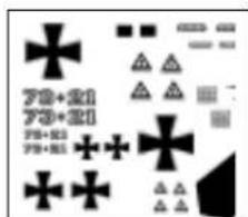
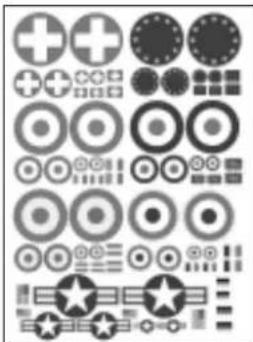
26. Gilding the lily - applying the decals
The kit is supplied with a multi-colour decal sheet 3.
Cut out the individual name placards and emblems and apply them to the model in the position shown in the kit box illustration, or in an arrangement which you find pleasing.
The decals cannot be re-positioned once applied, so take care to place them carefully!
27. Preparations for the first flight
For the model's initial test-flight please wait for a day with as little breeze as possible. The evening hours often present ideally calm conditions.
Be sure to carry out a range-check before the first flight.
The range-check should be completed using the procedure described in your RC system instructions.
The transmitter and flight battery must first be fully charged, using the procedure recommended by the manufacturer. If you are not using a 2.4 GHz system, ensure that your channel is not already in use before switching the transmitter on.
Before carrying out the range-check ensure that there is nothing and nobody in the way of the propeller. It is always possible that the motor could burst into life unexpectedly!
If you encounter a problem, please don't risk a flight. If you cannot sort out the problem yourself, send the whole system (including battery, switch harness and servos) to the Service Department of your RC system manufacturer and ask them to check it.
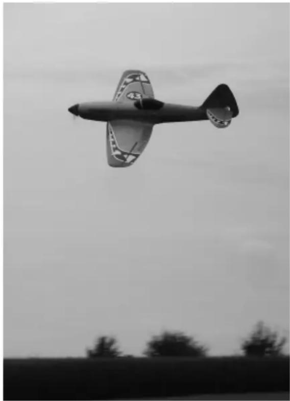
The first flight ...
The DogFighter should always be launched exactly into any wind.
If you are a beginner to model flying, or are not confident with this type of aeroplane, we strongly recommend that you ask an experienced model pilot to help you for the first few flights.
28. Hand-launching
Note for beginners: do not attempt to test-glide this model!
Test-gliding an aeroplane of this type always results in damage! The model should be hand-launched directly into wind, with the motor running at 3/4 -throttle.
If you have an experienced model launcher available, ask him or her to help you.
There are two possible methods:
Grasp the model from the underside, just aft of the wing; alternatively by the turtle deck, i.e. from above. The model's nose should be directed upwards by at least 45^ for a successful launch, and a slight bank to the right is also helpful.
Caution: the high motor torque will cause the model to attempt to roll to the left immediately after launch. However, an immediate and brief aileron command will straighten the model up without problem.
29. Safety
Safety is the First Commandment when flying any model aircraft. Third party insurance is a basic essential. If you join a model club suitable cover will usually be available through the organisation. It is your personal responsibility to ensure that your insurance is adequate.
Make it your job to keep your models and your radio control system in perfect order at all times.
Check the correct charging procedure for the batteries you are using. Make use of all sensible safety systems and precautions which are advised for your system. An excellent source of practical accessories is the MULTIPLEX main catalogue, as our products are designed and manufactured exclusively by practising modellers for other practising modellers.
Always fly with a responsible attitude. You may think that flying low over other people's heads is proof of your piloting skill; others know better. The real expert does not need to prove himself in such childish ways. Let other pilots know that this is what you think too.
Always fly in such a way that you do not endanger yourself or others. Bear in mind that even the best RC system in the world is subject to outside interference. No matter how many years of accident-free flying you have under your belt, you have no idea what will happen in the next minute.
We - the MULTIPLEX team - hope you have many hours of pleasure building and flying your new model.
MULTIPLEX Modellsport GmbH & Co. KG Product development and maintenance

K.laus Michler
Replacement parts
22 4581 Fuselage shells + 'snakes'
224583 Canopy
224590 Wing
224584Tailplane
22 4115 Small parts set and motor mounts
70 3455 Swivel pushrod connector, pack of 2
71 3338 M5 x 35 plastic screws, pack of 10
724580Decalsheet
725136 Canopy-Lock (2 pairs)
73 3115 10" x 7" propeller, 'Tuning'
73 3117 9" x 6" propeller, 'ULTRA Speed'
33 2326 Propeller driver
22 4207 ELAPOR spinner, 62mm , incl. holder
Part No. Description Material Dimensions
No. off
1.1 Building instructions
31 Decal sheet, racer Printed adhesive film 330 × 700 ~mm
31 Decal sheet, fighter Printed adhesive film 330 × 700 ~mm
41 L.H. fuselage shell Moulded Elapor foam Ready made
51 R.H. fuselage shell Moulded Elapor foam Ready made
61 Fuselage in-fill piece Moulded Elapor foam Ready made
71 Wing Moulded Elapor foam Ready made
81 Canopy
9 1 Tailplane
10 1 Spinner
Moulded Elapor foam Ready made
Moulded Elapor foam
Black EPP
Ready made
Ready made, 62 mm
Small parts set
20 3 Velcro tape, hook
21 3 Velcro tape, loop
22 2 Latch catch
23 2 Latch tongue
24 2 Glue-fitting horn
25 2 Swivel pushrod connector
26 2 Washer
27 2 Nut
28 2 "Twin" control surface horn
29 2 Articulated pivot barrel
30 4 Allen-head grubscrew
31 1 Allen key
32 2 Screw
33 2 Wing spreader plate A
34 2 Wing spreader plate B
35 2 Glue-fitting screw bush, M5
36 1 Firewall
37 2 Motor mount
38 4 Firewall adjuster screw
39 2 Firewall attachment screw
40 1 Battery bearer plate
41 1 Battery retainer strap
42 2 "Nano" servo mounting frame, upright
43 1 L.H. pushrod fairing
44 1 R.H. pushrod fairing
45 2 Aileron pushrod, one Z-bend
46 1 Elevator pushrod, one Z-bend
47 1 Rudder pushrod, one Z-bend
48 1 Spinner holder
Plastic
Plastic
Inj.-moulded plastic
Inj.-moulded plastic
Inj.-moulded plastic
Metal
Metal
Metal
Inj.-moulded plastic
Metal
Metal
Metal
Plastic
Inj.-moulded plastic
Inj.-moulded plastic
Inj.-moulded plastic
Inj. moulded plastic
Inj.-moulded plastic
Metal
Metal
Inj.-moulded plastic
Plastic
Inj.-moulded plastic
Inj.-moulded plastic
Inj.-moulded plastic
Metal
Metal
Metal
Inj.-moulded plastic
25 × 60 ~mm
25 × 60 ~mm
Ready made
Ready made
Ready made
Ready made, 6 mm
M2
M2
Ready made
Ready made, 0 6 mm
M3×3mm
1.5 mm A/F
M5×35mm
Ready made, M5
Ready made, M5
Ready made
Ready made
Ready made
M3 x 10 mm
M3×16mm
20 × 60 ~mm
16× 200mm
Ready made
Ready made
Ready made
10×70mm
10x80mm
10x110mm
Ready made
Spar and spar cap set
CFRP main wing spar
51 2 'Snake'outer sleeve
52 3 GRP spar cap
Rectangular CFRP strip
Plastic
GRP
6 × 1.5 × 225 ~mm
3/20x415mm
1.30x800mm
RR Dogfighter (only available in RR-version)
60 3 Servo and output arm
Nano-S UNI
Power system parts for RR version
61 1 Brushless outrunner motor
62 1 Brushless speed controller
63 1 Propeller driver
64 1 Propeller
65 4 Screw
66 4 Washer
67 2 Servo extension lead
Metal
MULTIcont BL-40 S-BEC
Metal
Plastic
Metal
Metal
Himax C 3516-1130
ACC 370
10 × 7'' APC-E
M3 x 12 mm
M3
150 mm
RR instructions
1.1 1 Supplementary instructions, RR
1.2 1 Power set instructions
1.3 1 Speed controller instructions
Fuselage shells + 'snakes'
Small parts set and motor mounts
Swivel pushrod connector, pack of 2
Tringle de commande 2 pcs.
M5 x 35 plastic screws, pack of 10
Vis M5x35 10 pcs.