Kit ParkMaster 3D - Remote control toy MULTIPLEX - Free user manual and instructions
Find the device manual for free Kit ParkMaster 3D MULTIPLEX in PDF.

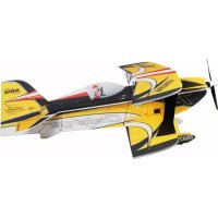
| Product Type | Radio-controlled toy - 3D aerobatic airplane |
| Brand | MULTIPLEX |
| Model | ParkMaster 3D Kit |
| Wingspan | 960 mm |
| Fuselage Length | 1000 mm |
| Flying Weight | 525 g (with recommended equipment) |
| Wing Area | 29 dm² |
| Wing Loading | From 18 g/dm² |
| Construction Materials | ELAPOR® (foam), fiberglass, injected plastic, metal |
| RC Functions | Rudder, elevator, aileron, throttle (4 channels) |
| Recommended Propulsion | Himax 2816-0890 motor, BL-17 II speed controller, APC 11x5.5" propeller. LiPo 3S 1950 mAh battery |
| Recommended Receiver | RX-6 SYNTH light 35 MHz (or 40/41 MHz) |
| Recommended Servos | Nano-Karbonite (4×) |
| Center of Gravity (CG) | 110 to 120 mm from the leading edge of the wing (measured at the fuselage) |
| Control Surface Deflections (first flight recommendations) | Aileron: 65 mm, Elevator: 65 mm, Rudder: 90 mm |
| Recommended Glue Type | Medium viscosity cyanoacrylate (instant) glue - Zacki ERLAPOR® #59 2727 |
| Safety Instructions | Check motor/propeller attachments before flight, keep fingers away from propeller, do not fly towards people, liability insurance required |
| Maintenance and Cleaning | Clean with a soft dry cloth, avoid solvents; regularly check the condition of hinges and pushrods |
| Spare Parts and Reparability | Parts available via MULTIPLEX dealer; ELAPOR foam repairable with cyanoacrylate glue |
| General Information | Assembly kit requiring gluing and adjustments; intended for pilots with modeling experience |
Frequently Asked Questions - Kit ParkMaster 3D MULTIPLEX
User questions about Kit ParkMaster 3D MULTIPLEX
0 question about this device. Answer the ones you know or ask your own.
Ask a new question about this device
Download the instructions for your Remote control toy in PDF format for free! Find your manual Kit ParkMaster 3D - MULTIPLEX and take your electronic device back in hand. On this page are published all the documents necessary for the use of your device. Kit ParkMaster 3D by MULTIPLEX.
USER MANUAL Kit ParkMaster 3D MULTIPLEX
Before every flight check that the motor and propeller are in place and secure - especially after transporting the model, and after hard landings and crashes. Check also that the wing is correctly located and firmly secured on the fuselage before each flight.
Don't plug in the battery until you have switched on the transmitter, and you are sure that the motor control on the transmitter is set to "OFF".
When the model is switched on, ready to fly, take care not to touch the propeller. Keep well clear of the propeller disc too, and ask spectators to stay back.
Allow the motor to cool down after each flight. You can check this by carefully touching the motor case with your finger. The temperature is correct when you can hold your finger on the case without any problem. On hot days this may take up to 15 minutes.
Please keep in mind at all times: don't fly towards people or animals.
I Note di sicurezza
Expo Quer 30%, Höhe 50%
18. Einfliegen:
Basic information relating to model aircraft
natural_image
Diagram of a helicopter in flight with labeled point B and directional arrow (no text or symbols beyond label)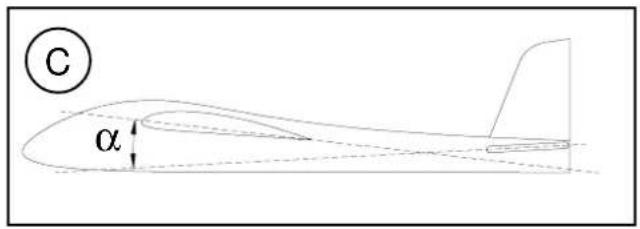
text_image
C α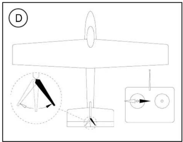
text_image
D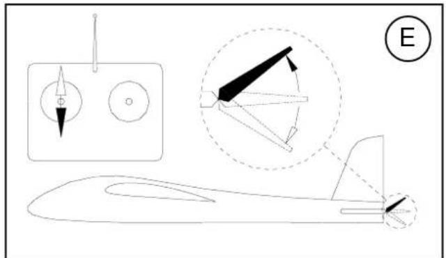
natural_image
Line drawing of a small aircraft with internal components and a labeled section (E), no text or symbols present.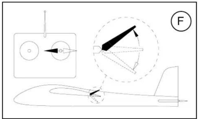
natural_image
Technical line drawing of an aircraft with component details and a labeled section (F), no readable text or symbols present.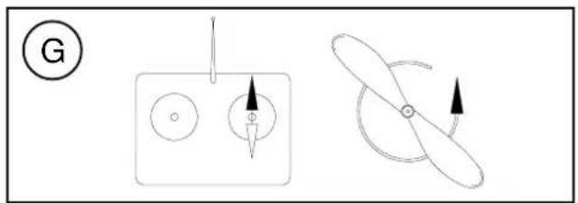
natural_image
Diagram showing two mechanical or electrical components with arrows indicating direction (no text or symbols)Examine your kit carefully!
MULTIPLEX model kits are subject to constant quality checks throughout the production process, and we sincerely hope that you are completely satisfied with the contents of your kit. However, we do ask you to check all the parts before you start construction (referring to the Parts List), as we cannot exchange components which you have already worked on. If you find any part is not acceptable, we will readily correct or exchange it once we have examined it. Just send the component to our Model Department. Please be sure to include the purchase receipt and the completed complaint form, which is included in the kit.
We are constantly working on improving our models, and for this reason we must reserve the right to change the kit contents in terms of shape or dimensions of parts, technology, materials and fittings, without prior notification. Please understand that we cannot entertain claims against us if the kit contents do not agree in every respect with the instructions and the illustrations.
Caution!
Radio-controlled models, and especially model aircraft, are by no means playthings. Building and operating them safely requires a certain level of technical competence and manual skill, together with discipline and a responsible attitude at the flying field. Errors and carelessness in building and flying the model can result in serious personal injury and damage to property. Since we, as manufacturers, have no control over the construction, maintenance and operation of our products, we are obliged to take this opportunity to point out these hazards and to emphasise your personal responsibility. Even though the model is called the "ParkMaster 3D", you can only fly in the park if model flying is expressly permitted there.
Additional items required for the "ParkMaster 3D":
MULTIPLEX radio control components for the ParkMaster 3D:
MULTIPLEX RX-6-SYNTH light receiver
35 MHz A+B band
Order No. 5 5876
alternatively: 40 / 41 MHz band Order No. 5 5877
Nano-Karbonite servo (four required) 2 x aileron, 1 x
elevator, 1 x rudder Order No. 6 5118
Possibly 200 mm UNI suppressor filter lead (for speed controller) Order No. 8 5035
Battery charger:
MULTIcharger LN-3008 EQU Order No. 9 2540
For 2S and 3S LiPo, Lilo and LiFe batteries, and
4-cell to 8-cell NiMH and NiCd batteries
ParkMaster 3D power set
Contents: Order No. 33 2638
Himax 2816-0890 motor, BL-17 II speed controller, APC 11 x 5.5" propeller, taper collet and propeller driver.
Flight battery Li-BATT BX-3/1 950 Order No. 15 7116
Tools:
Scissors, balsa knife, combination pliers, side-cutters.
Note: please remove the illustration pages from the centre of the instructions.
Specification:
| Wingspan: | 960 mm |
| Overall length: | 1000 mm |
| All-up weight approx.: | 525 g |
| Total surface area: | 29 dm ^2 |
| Wing loading min.: | 18 g/dm ^2 |
| RC functions: | Aileron, elevator, rudder, throttle |
Important note
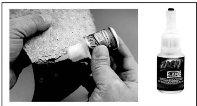
This model is not made of styrofoam™, and it is not possible to glue the material using white glue, polyurethane or epoxy; these adhesives only produce a superficial bond which simply gives way when stressed. Please use medium-viscosity cyano-acrylate glue exclusively, preferably our Zacki-ELAPOR®, # 59 2727 - the cyano glue optimised specifically for ELAPOR® particle foam.
If you use Zacki-ELAPOR® you will find that you do not need cyano kicker or activator for most joints. However, if you wish to use a different adhesive, and are therefore obliged to use kicker / activator spray, we recommend that you apply the material in the open air to avoid health problems.
1. Before assembling the model
Check the contents of your kit before you start working on it. You will find Figs. 1 + 2 and the Parts List helpful here.
Note: the GRP spars and longerons 40 - 43 are supplied in the kit as one full-length strip 14, and have to be cut to the correct length. Please cut them as follows:
40 2 x L.H. and R.H. fuselage longerons 1.3 ∅ x 745 mm
41 2 x L.H. and R.H. motor mount supports 1.3 ∅ x 120 mm
42 2 x top and bottom wing spars 1.3 ∅ x 855 mm
43 2 x top and bottom tailplane spars 1.3 ∅ x 400 mm
Alternatively you can cut the strips to the length of the moulded foam components.
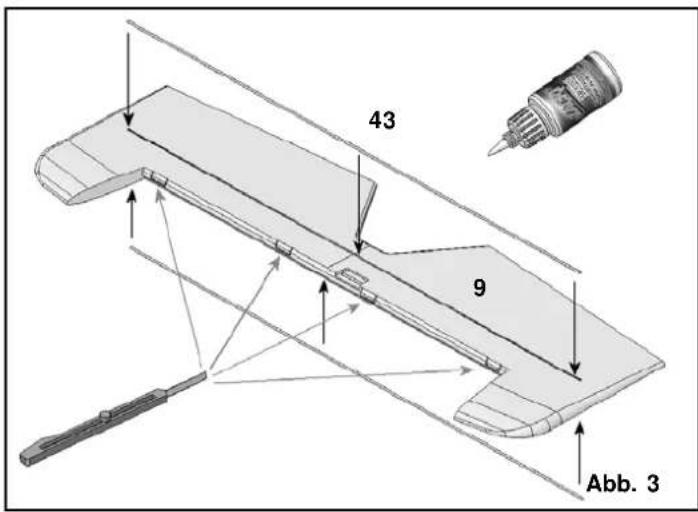
2. Preparing the elevator (9)
Lay the elevator 9 flat on the workbench and weight it down temporarily. Glue the spars 43 in place, wiping off excess glue immediately with a cloth. Use a balsa knife to cut slots at the marked points for the hinges 22.
Fig. 03
Prepare the elevator horn 23 as shown in Fig. 04, and glue it in the recess in the elevator 9.
3. Preparing the rudder
Use a balsa knife to cut the slots for the rudder hinges 22.
Fig. 05
Prepare the rudder horn 23 as shown in Fig. 06, and glue it in the slot.
4. Preparing the ailerons (6 + 7)
Here again use a balsa knife to cut slots for the hinges 22 at the marked points. Fig. 7. Prepare the aileron horns 23 as shown in Fig. 08, and glue them in the slots; make sure the horns and swivel connectors are fitted the right way round.
5. Preparing the fuselage 3
To improve the visibility of the model in flight we advise you to pick out the canopy in a dark colour, and this is easiest to do at this stage. Mask out the canopy with adhesive tape before painting; we recommend the use of spray cans. Paint is heavy, so keep the application of colour as light as possible.
6. Installing the motor mount
Glue the plastic motor mount components 35 + 36 in place as shown in Fig. 09, followed by the motor mount supports 41 on both sides.
Fig. 10
7. Installing the fuselage longerons
Lay the fuselage 3 down on a flat bench, with one fuselage longeron channel facing down, and fit one fuselage longeron in the longeron channel facing you; run cyano along the joint. Allow the glue to set hard, then repeat the procedure on the other side to form a mirror-image.
Fig. 11
Trial-fit the elevator and rudder servos in their recesses in the fuselage, and secure each with a drop of cyano applied to the mounting lugs. Deploy the leads forward towards the receiver.
Fig. 12
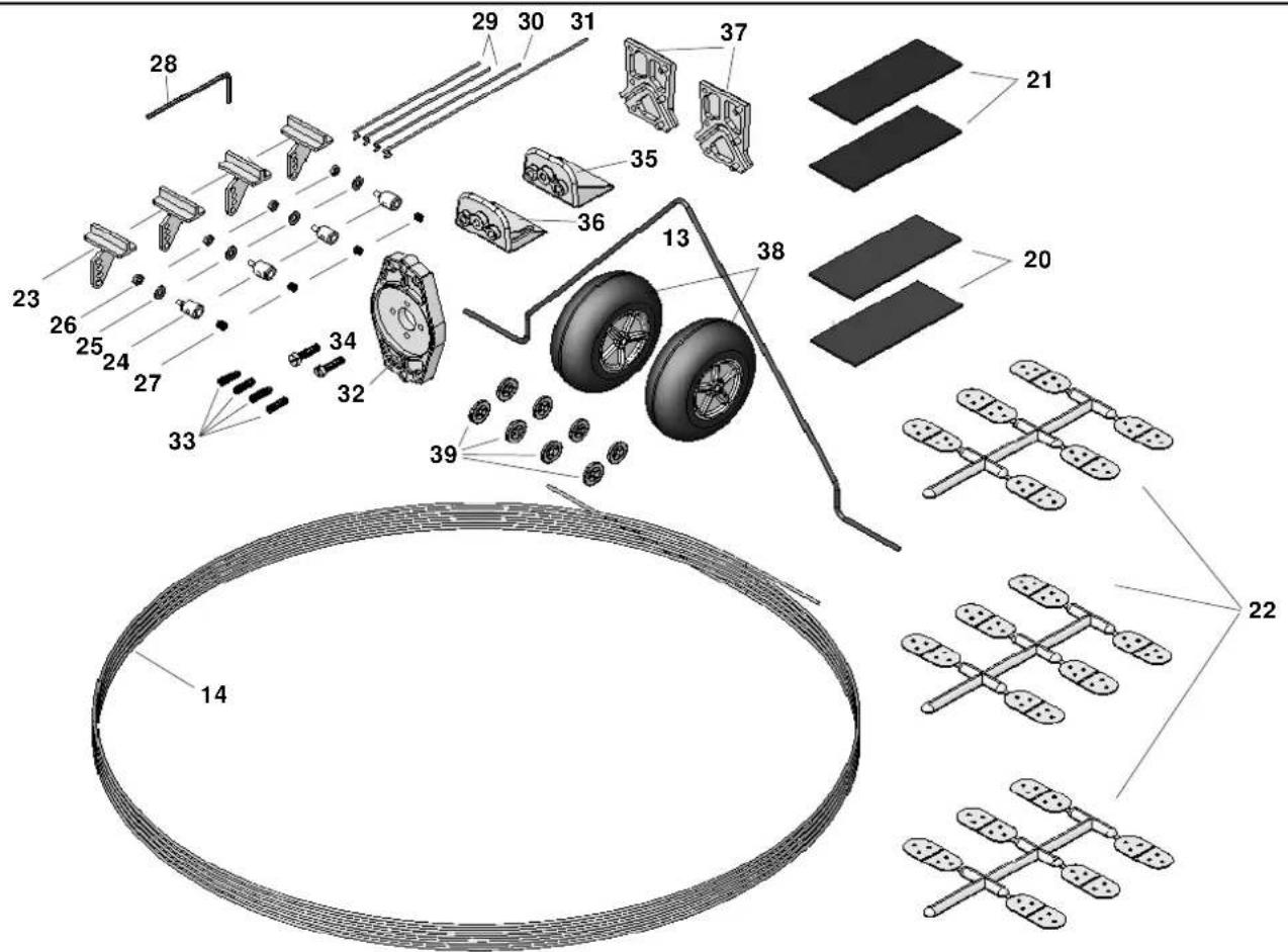
8. The main undercarriage 13
The first step is to remove any rough edges from the ends of the wire main undercarriage unit, and check that its shape is exactly as shown. Fit the first starlock washer 39 on one wheel axle by laying a pair of pliers on the bench with the jaws slightly open, as shown in Fig. 13, and pressing the wire unit 13 through the washer. Once the starlock washer is on the axle you will find that it can be pushed into final position; the free end of each wheel axle should be 24 mm long.
Place both undercarriage supports 37 over the wire unit 13 as shown, slip this assembly into the fuselage from the side, and glue it in place carefully.
Fig. 14
The first starlock washer can now be fitted on the second wheel axle, using the pair of pliers again. Now fit the wheels and secure them with the second starlock washers. Allow the wheels just sufficient clearance for them to spin freely.
Fig. 15
Now glue the undercarriage leg fairings 11 + 12 in place as shown, taking care to glue them to the wire legs only; do not glue them to the fuselage at the top, as this would restrict the springing effect of the steel.
Figs. 16 + 17
9. Completing the wing
Glue the wing panels 4 + 5 together at the centre, taking particular care to ensure that they are not twisted relative to each other.
Fig. 18
Invert the joined wing and lay it down on a flat surface. After the first third the whole surface of the wing panels should make contact with the bench surface. Glue the bottom wing spar 42 in the appropriate channel.
Fig. 19
Turn the wing over, lay one half-span down flat and weight it down temporarily. Glue the top spar in the channel of the weighted wing panel only.
Fig. 20
Allow the glue to harden, then pack up this side by 5 mm at the tip, and glue the spar to the second wing panel.
Fig. 21
Use a balsa knife to cut the slots at the marked points in the wings and the ailerons for the aileron hinges 22.
Fig. 22
10. Joining the wing and fuselage
Attach the left-hand aileron 6 to the left-hand wing panel 4 using the hinges 22. Secure each of the hinges 22 with a drop of cyano.
Fig. 23
Slide the wing, with one aileron attached, through the fuselage as shown in Fig. 24. Set the wing central, then attach the second aileron as shown in Fig. 25. Now position the wing carefully (square and at right-angles to the fuselage) and run cyano along the joint between the fuselage and the wing; don't allow excess glue to run out of the joints. Check the alignment of the wing once again, as shown in Figs. 26 and 27.
11. Installing the servos, connecting the control surfaces
Place the aileron servos in their recesses, and secure each with a drop of glue applied to the mounting lugs. Connect the preformed end of the pushrods 29 to the servo output arms. Slip the pushrods through the swivel pushrod connectors on the aileron horns, set the servos and ailerons to centre, then tighten the clamping screws in the connectors.
Fig. 28
12. Installing the tailplane and rudder
Trial-fit the tailplane 8 in its slot, and check that it is at right-angles to the fuselage. Carry out any trimming required, then glue it in place.
Fig. 29
Attach the rudder 10 to the fin using the hinges 22.
Fig. 30
13. Connecting the servos to the elevator and rudder
If you are using servos other than those recommended, you may need to use different linkage holes - adjust as necessary.
Connect the pre-formed end of the rudder pushrod to the outermost hole in the servo output arm. The swivel connector should be mounted in the third hole from the outside of the horn in the rudder 10. Tighten the nut of the pushrod connector just to the point where the barrel swivels smoothly, but without slop. Apply a tiny drop of thread-lock fluid or cyano to the outside of the nut to secure it.
Repeat the procedure with the elevator pushrod 30.
Fig. 31
14. Installing the motor
If you are using the dedicated power set # 33 2638 you will have no problems at this stage: everything fits, and the model is very adequately powered. The method of installing the motor mount 32 and the motor is shown in Fig. 32.
15. Centre of Gravity
The CG should be corrected as far as possible when you install the flight battery.
The model should balance at a point in the range 110 - 120 mm aft of the wing root leading edge, measured on both sides of the fuselage. Fig. 33
16. Initial test-run
Install all the receiving system components as shown in Fig. 34, and connect them as described in the RC system instructions; use the Velcro tape 20 + 21 to secure the components. Check the neutral position and freedom of movement of the control surfaces, and the direction of rotation of the servos. Check the direction of motor rotation, and reverse it if necessary.
17. Settings (guide only!)
Centre of Gravity (CG): approx. 110 - 120 mm aft of the wing root leading edge
Longitudinal dihedral: 0°
Downthrust: 0 - 2° (motor shaft angled down)
Sidethrust: 0 - 2° (motor shaft angled to the right)
Adjustments are possible using the set-screws in the motor bulkhead.
Control surface travels:
Measured at the widest point of the control surfaces
Ailerons: 65 mm
Elevator: 65 mm
Rudder: 90 mm
Dual Rates on elevator and ailerons: 30 - 50%
Exponential: ailerons 30%, elevator 50%
18. Test-flying
Wait for a day with flat-calm conditions or very little wind.
Carry out all adjustments beforehand, in the calm of your workshop!
Longitudinal dihedral = 0°. The design of the model automatically sets this correctly.
Balancing:
Start by balancing the model within the stated range. Once you have completed the initial test-flights, you can fine-tune the setting as follows: fly straight and level at half-throttle, and roll the model inverted. If you now have to apply a great deal of "down" to hold level flight, the model is nose-heavy; the CG must be shifted further aft. If the machine climbs whilst inverted, without requiring elevator correction, the CG is too far aft. When balanced correctly, the model will require slight down-elevator for level inverted flight.
Correcting straight and level flight:
First the static balance: support the model by the spinner and the rudder: with the fuselage level, the wings should remain horizontal. If not, add ballast to the lighter wingtip.
On the next flight, fly the aeroplane at minimum throttle (just enough power to keep the model in the air), hold it straight and level, and adjust the trims for straight flight. Now switch to inverted and check the straight flying characteristics. If necessary, adjust the wingtip ballast after landing the model.
Sidethrust:
Apply full throttle and fly the model straight and level past yourself before pulling up into a vertical climb. When ascending vertically the model should not exhibit any tendency to veer off to right or left. If this is not the case, adjust the sidethrust to correct the fault. Repeat the test several times, as any sidewind will tend to falsify the model's track.
Downthrust:
Apply full throttle and fly the model straight and level until it arrives at your location, so that you have a clear view of the model from one side. Pull the aircraft up into a vertical climb: it should continue to climb vertically, and not fall away forward or back. If this is not the case, adjust the motor downthrust to correct the fault.
After these checks you may find it necessary to repeat the CG tests.
Aileron differential:
Fly three or four rolls to the right at half-throttle; if the aircraft veers to the right during this manoeuvre, you need to increase the aileron differential. If it veers to the left, i.e. against the direction of rolling, you should reduce the aileron differential.
19. Gilding the lily - applying the decals
The kit is supplied with a multi-colour decal sheet 2. Cut out the individual name placards and emblems and apply them to the model in the position shown in the kit box illustration, or in an arrangement which you find pleasing.
20. Safety
Safety is the First Commandment when flying any model aircraft. Third party insurance should be considered a basic essential. If you join a model club suitable cover will usually be available through the organisation. It is your personal responsibility to ensure that your insurance is adequate (i.e. that its cover includes electric / glow powered model aircraft).
Make it your job to keep your models and your radio control system in perfect order at all times. Check the correct charging procedure for the batteries you are using. Make use of all sensible safety systems and precautions which are advised for your system. An excellent source of practical accessories is the MULTIPLEX main catalogue, as our products are designed and manufactured exclusively by practising modellers for other practising modellers.
Always fly with a responsible attitude. You may think that flying low over other people's heads is proof of your piloting skill; others know better. The real expert does not need to prove himself in such childish ways. Let other pilots know that this is what you think too. Always fly in such a way that you do not endanger
yourself or others. Bear in mind that even the best RC system in the world is subject to outside interference. No matter how many years of accident-free flying you have under your belt, you have no idea what will happen in the next minute.
We - the MULTIPLEX team - hope you have many hours of pleasure building and flying your new model.
Product development and maintenance
Klaus Michler
ParkMaster 3D
Part No. Description Material Dimensions
No. off
| 1 | 1 | Building instructions Paper, 80 g/m2 A4 | |||
| 2 | 1 | Decal set Printed adhesive film 500 x 1000 mm | |||
| 3 | 1 | Fuselage | Moulded Elapor foam | Ready made | |
| 4 | 1 | L.H. wing panel | Moulded Elapor foam | Ready made | |
| 5 | 1 | R.H. wing panel | Moulded Elapor foam | Ready made | |
| 6 | 1 | L.H. aileron | Moulded Elapor foam | Ready made | |
| 7 | 1 | R.H. aileron Moulded Elapor foam | Ready made | ||
| 8 | 1 | Tailplane | Moulded Elapor foam | Ready made | |
| 9 | 1 | Elevator | Moulded Elapor foam | Ready made | |
| 10 | 1 | Rudder | Moulded Elapor foam | Ready made | |
| 11 | 1 | L.H. undercarriage fairing | Moulded Elapor foam | Ready made | |
| 12 | 1 | R.H. undercarriage fairing | Moulded Elapor foam | Ready made | |
| 13 | 1 | Main undercarriage unit | Spring steel wire | 2 mm ∅, ready made | |
| 14 | 1 | GRP spar / longeron material (roll) | GRP | 1.3 ∅ x 4500 mm | |
Small items
| 20 | 2 | Velcro tape, “mushroom” | Plastic | 25 x 60 mm |
| 21 | 2 | Velcro tape, “felt” | Plastic | 25 x 60 mm |
| 22 | 3 | Leaf hinge (sprue of six) | Inj. moulded plastic | Ready made |
| 23 | 4 | Glue-fitting control surface horn | Inj. moulded plastic | Ready made |
| 24 | 4 | Swivel pushrod connector | Metal | Ready made, 6 mm ∅ |
| 25 | 4 | Washer | Metal | M2 |
| 26 | 4 Nut | Metal | M2 | |
| 27 | 4 | Socket-head grubscrew | Metal | M3 x 3 mm |
| 28 | 1 | Allen key | Metal | 1.5 mm A/F |
| 29 | 2 | Pre-formed aileron pushrod | Metal | 1 ∅ x 70 mm |
| 30 | 1 | Pre-formed elevator pushrod | Metal | 1 ∅ x 80 mm |
| 31 | 1 | Pre-formed rudder pushrod | Metal | 1 ∅ x 110 mm |
| 32 | 1 | Motor bulkhead | Inj. moulded plastic | Ready made |
| 33 | 4 Socket-head grubscrew | |||
| Motor bulkhead adjustment | Metal | M3 x 10 mm | ||
| 34 | 2 | Motor bulkhead retaining screw | Metal | M3 x 12 mm |
| 35 | 1 | Top motor mount | Inj. moulded plastic | Ready made |
| 36 | 1 | Bottom motor mount, with notch /Nut | Inj. moulded plastic | Ready made |
| 37 | 2 | Undercarriage support | Inj. moulded plastic | Ready made |
| 38 | 2 | Lightweight wheel | EPP plastic | 53 ∅, hub bore 2.6 mm |
| 39 | 9 | Starlock washer | Metal | For 2 mm ∅ |
| 1 | GRP spar material (roll) | GRP rod | 1.3 ∅ x 4500 mm | |
| To be cut to length as follows: | ||||
| 40 | 2 | L.H. and R.H. fuselage longeron | GRP rod | 1.3 ∅ x 745 mm |
| 41 | 2 | L.H. and R.H. motor mount support | GRP rod | 1.3 ∅ x 120 mm |
| 42 | 2 | Top and bottom wing spar | GRP rod | 1.3 ∅ x 855 mm |
| 43 | 2 | Top and bottom tailplane spar | GRP rod | 1.3 ∅ x 400 mm |
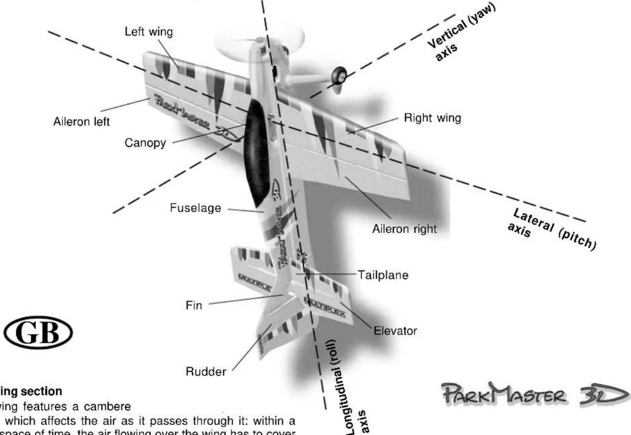
The basics of flying - using a model aircraft as an example
Any aircraft - full-size or model - can be controlled around three primary axes: the vertical (yaw) axis, the lateral (pitch) axis and the longitudinal (roll) axis. Operating the elevator produces a change in the model's flight attitude around the lateral axis (nose up or down). External influences such as air turbulence constantly tend to divert the model from its intended flight path, and it is the pilot's job to control the model actively in such a way that it flies where he or she wants it to. The aircraft's altitude is controlled using the power system (motor and propeller). In our models the rotational speed of the propeller is usually controlled proportionally by means of an electronic speed controller. Although applying up-elevator will make the model climb, it is important to understand that it will also make it slow down, i.e. the aircraft will only continue to climb until its airspeed falls to the minimum flying speed (stall speed). Opening the throttle (increasing power) will enable the model to continue climbing, i.e. the power of the motor dictates the maximum climb angle.
text_image
Left wing Vertical (yaw) axis Aileron left Canopy Right wing Fuselage Tailplane Elevator Rudder Longitudinal (roll) axis Lateral (pitch) Aileron right Fin MUDBOX MUDBOX PUNDBOX GB ing section ing features a cambere which affects the air as it passes through it: within a space of time, the air flowing over the wing has to cover PARKMASTER 3DThe wing section
The wing features a cambere
airfoil) which affects the air as it passes through it: within a given space of time, the air flowing over the wing has to cover a longer distance than the air flowing under the wing. This generates a low-pressure area on the top surface of the wing which tends to create lift, holding or raising the aircraft in the air. Fig. A
The Centre of Gravity
If your Mentor is to fly safely and stably it must balance at the correct point - just like every other aircraft. It is absolutely essential to set the correct CG (balance point) before you fly the model for the first time.
The stated CG position is measured from the root leading edge of the wing (on either side of the fuselage). Support the model on your fingertips at these points, and it should balance level. Even better: use the MPX CG gauge, # 69 3054. Fig. B If necessary, adjust the position of the flight battery until this is the case. If you still cannot set the balance point correctly, add ballast (lead, plasticene, modelling clay) to the nose or tail to correct it. If ballast is needed, fix it very securely. If the model is tail-heavy, the ballast must be fixed in the fuselage nose. If it is nose-heavy, the ballast is fixed at the tail end of the fuselage.
The longitudinal dihedral (difference between the wing and tailplane incidence) is also important. Provided that you attach the wing and tailplane to the fuselage exactly as described in these instructions, this parameter will automatically be correct.
If both these settings - centre of gravity and longitudinal dihedral - are correct, you will have no problems flying the model, and the test-flying process will be straightforward. Fig. C
Control surfaces, control surface travels
The model will only be able to offer safe, accurate flying characteristics if the control surfaces move freely, deflect in the correct directions, and move to the appropriate angles. The control surface travels stated in the building instructions have been established as a result of practical flight testing, and we strongly recommend that you keep to them - at least initially. You may wish to adjust them later to suit your style of flying, and this is a straightforward procedure.
Transmitter control function arrangements
The transmitter is fitted with two primary sticks which control the servos in the model; the servos in turn move the control surfaces. The arrangement of the control functions shown here corresponds to Mode A, but other stick modes are possible.
The transmitter is used to operate the control surfaces as follows:
The rudder (left / right) Fig. D
The elevator (up / down) Fig. E
The ailerons (left / right) Fig. F
The throttle (motor off / on) Fig. G
The throttle (motor control) stick must stay in the set position by itself, i.e. it must not be self-centring. For this reason the throttle stick is usually set up with a ratchet. If your transmitter is not set up in this way, please read the operating instructions supplied with the RC set to find out how to set up the throttle ratchet.
Basic information relating to model aircraft
natural_image
Line drawing of a submarine with internal components and a labeled section (E), no text or symbols present.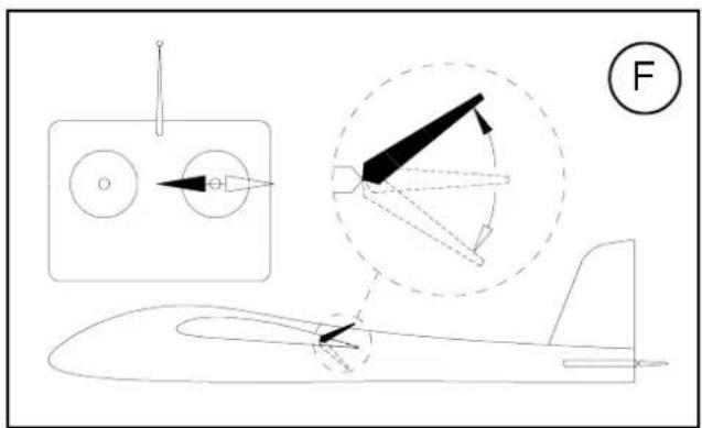
text_image
Technical diagram showing aircraft wing structure with labeled components and a force indicator (F)
natural_image
Diagram showing two mechanical or electrical components with arrows indicating direction (no text or symbols)text_image
Exploded view diagram of a 3D aircraft fuselage with numbered components for identificationAbb. 1
text_image
Exploded view diagram of a vehicle's internal components with numbered parts and a circular component labeled 14.Abb. 2
text_image
43 9 Abb. 3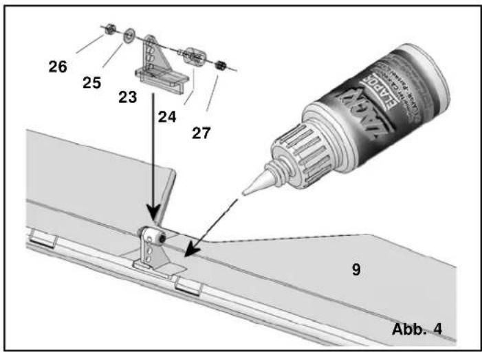
text_image
26 25 23 24 27 9 Abb. 4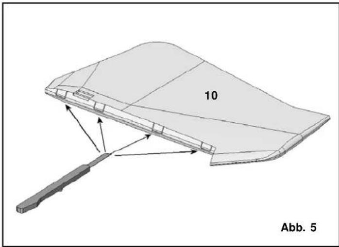
natural_image
3D diagram of a curved structural component with labeled part '10' and directional arrows, no readable text or symbols beyond label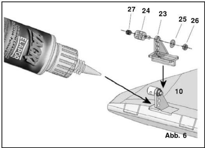
text_image
EATPO 27 24 23 25 26 10 Abb. 6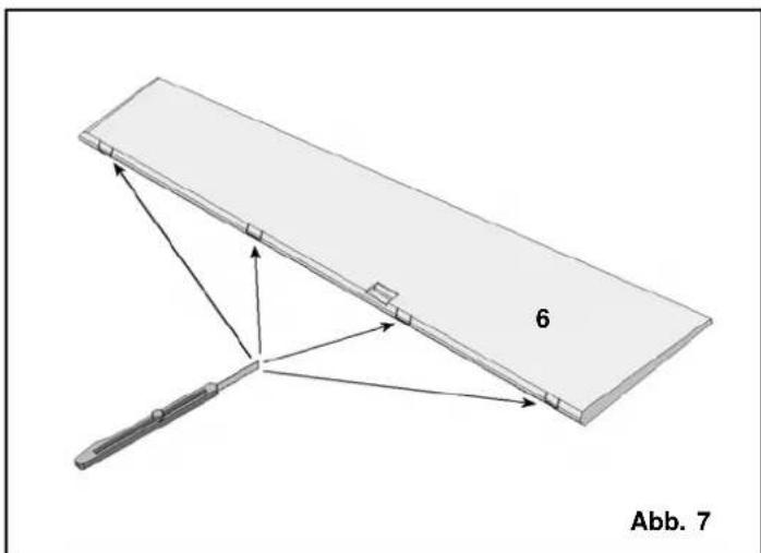
natural_image
Diagram of a mechanical device with labeled components and directional arrows, no readable text or symbols present.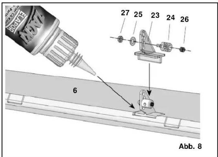
text_image
VEXV 6 27 25 23 24 26 Abb. 8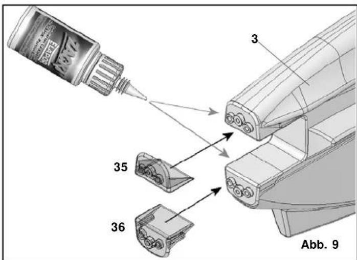
text_image
EABY 3 35 36 Abb. 9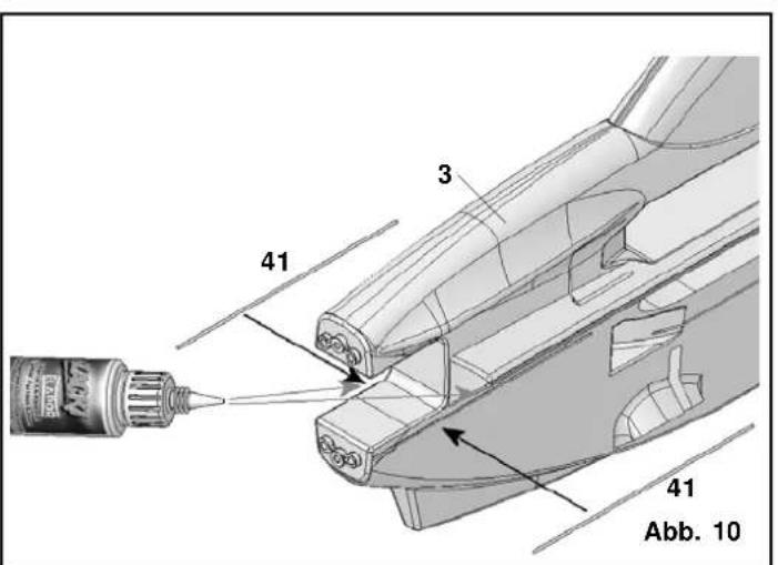
text_image
41 3 41 Abb. 10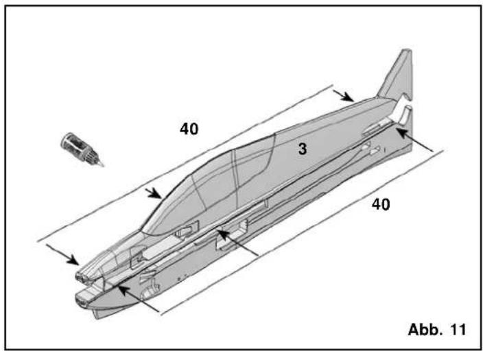
text_image
40 3 40 Abb. 11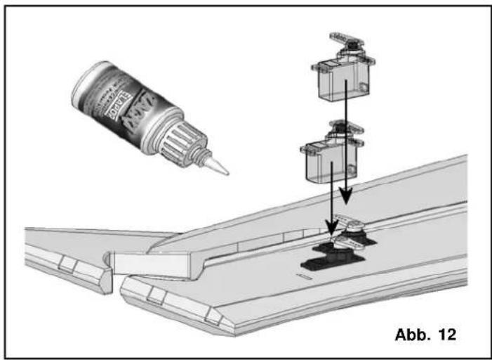
text_image
Abb. 12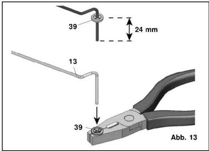
text_image
39 24 mm 13 39 Abb. 13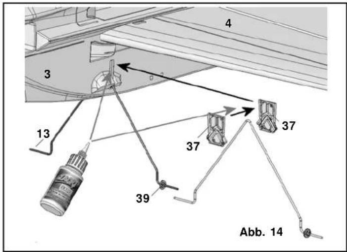
text_image
4 3 13 37 37 39 Abb. 14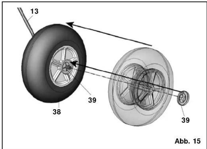
text_image
13 38 39 39 Abb. 15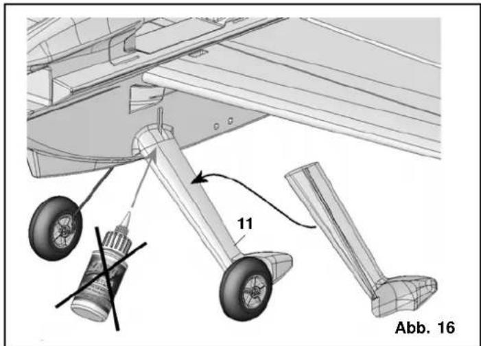
text_image
11 Abb. 16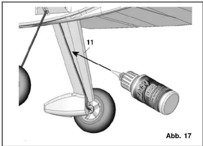
text_image
11 Abb. 17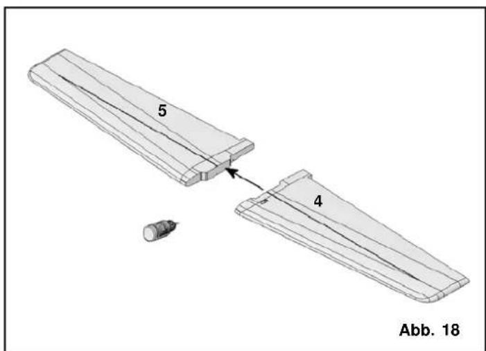
text_image
5 4 Abb. 18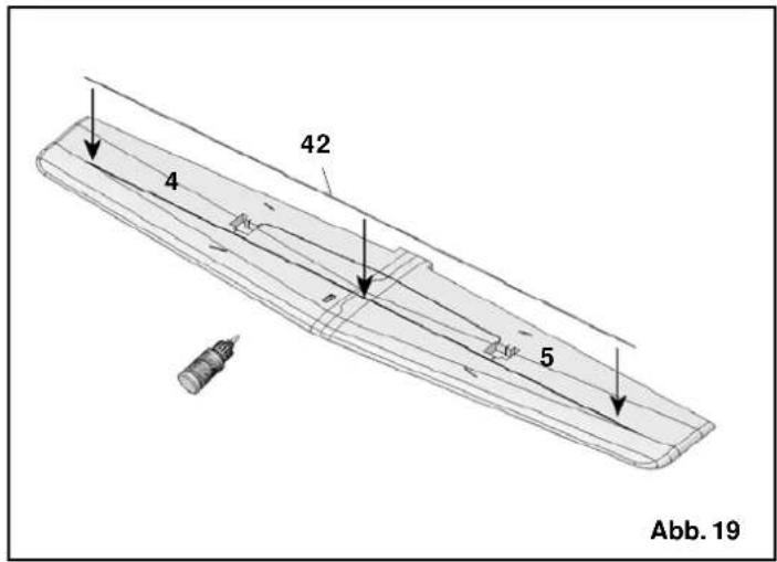
text_image
4 42 5 Abb. 19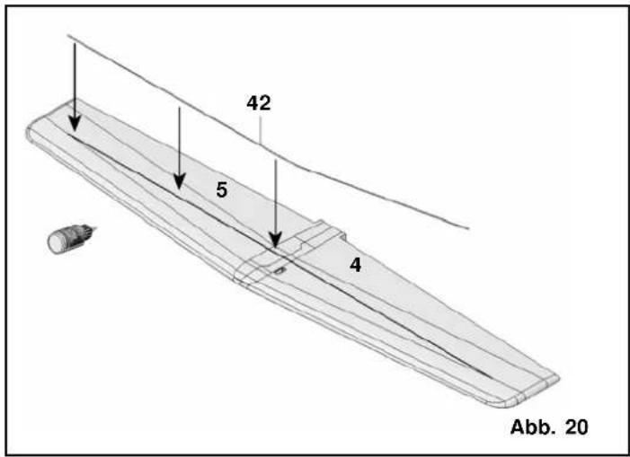
text_image
42 5 4 Abb. 20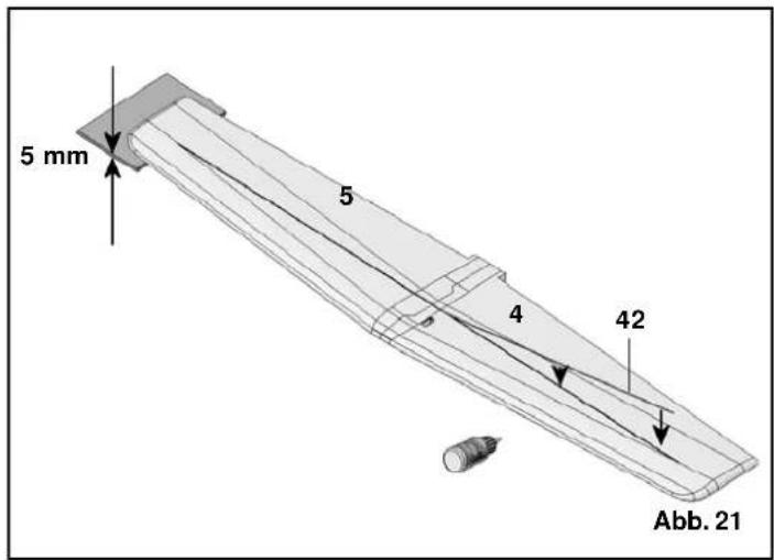
text_image
5 mm 5 4 42 Abb. 21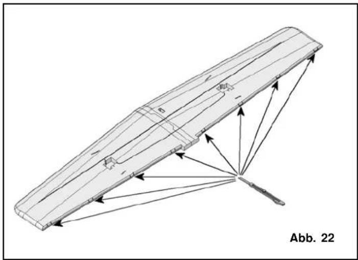
natural_image
Technical line drawing of a mechanical component with directional arrows indicating assembly or force (no text or symbols)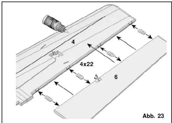
text_image
4 4x22 6 Abb. 23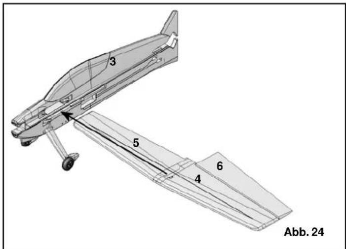
text_image
3 5 4 6 Abb. 24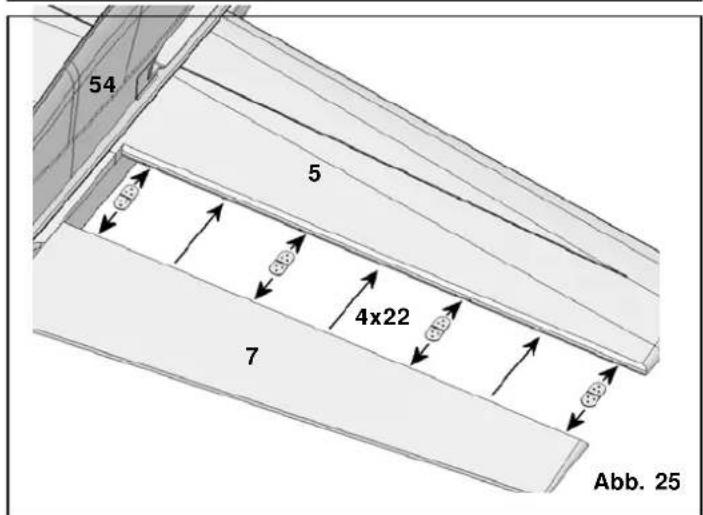
text_image
54 5 4x22 7 Abb. 25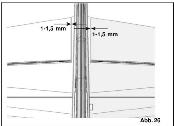
text_image
1-1,5 mm 1-1,5 mm Abb. 26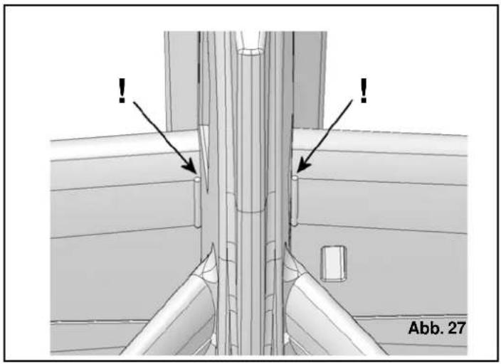
natural_image
Technical diagram showing pipe connection details with arrows and label Abb. 27 (no readable text or symbols beyond labels)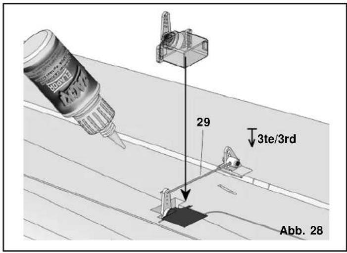
text_image
29 3te/3rd Abb. 28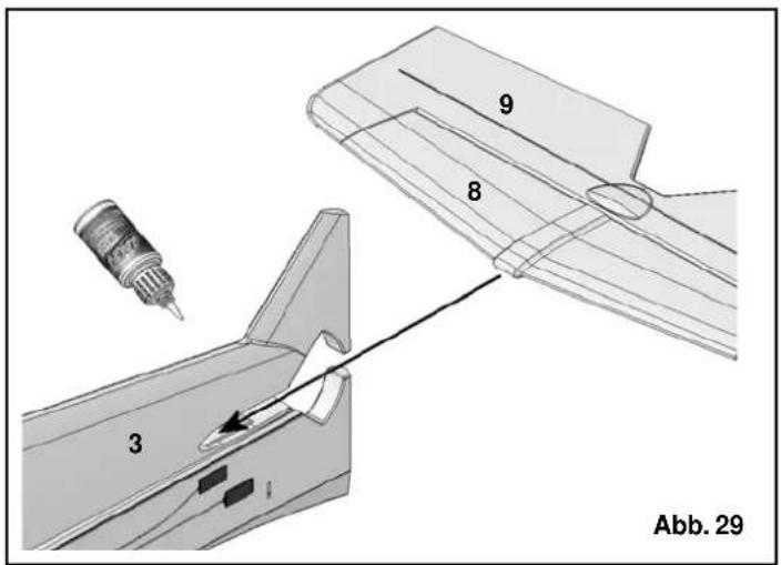
text_image
3 8 9 Abb. 29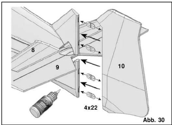
text_image
8 9 10 4x22 Abb. 30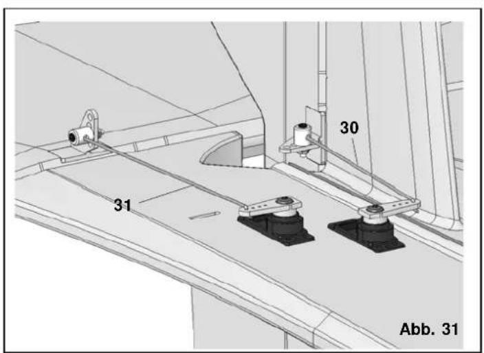
text_image
30 31 Abb. 31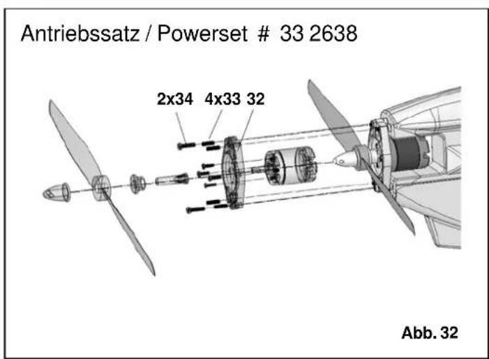
text_image
Antriebssatz / Powerset # 33 2638 2x34 4x33 32 Abb. 32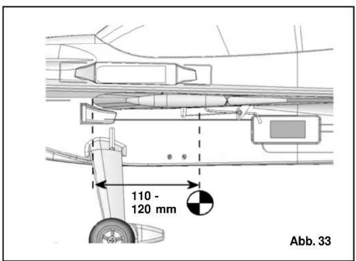
text_image
110 - 120 mm Abb. 33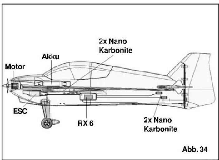
text_image
Motor Akku 2x Nano Karbonite ESC RX 6 2x Nano Karbonite Abb. 34Basic information relating to model aircraft
natural_image
Line drawing of a submarine with internal components and a labeled section E (no text or symbols on the diagram itself)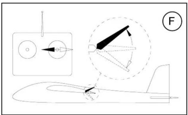
text_image
Technical diagram showing aircraft component assembly with labeled parts and a numbered circle indicator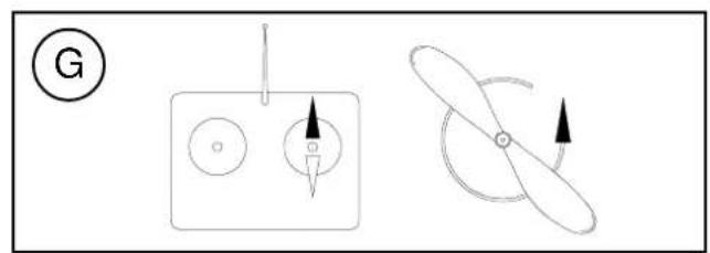
natural_image
Diagram showing three distinct mechanical or electrical components: a circular component with a pointer, a square with arrows indicating direction, and a propeller-like shape with an arrow indicating rotation (no text or symbols present)Basic information relating to model aircraft
natural_image
Technical line drawing of a missile or aircraft with multiple components and a labeled section (E), no readable text or symbols present.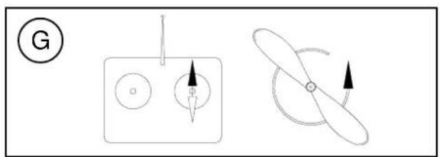
natural_image
Diagram showing two mechanical or electrical components with arrows indicating direction (no text or symbols)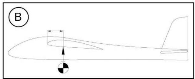
natural_image
Line drawing of a helicopter in flight with an arrow indicating speed and a black-and-white circle symbol at the bottom (no text or labels)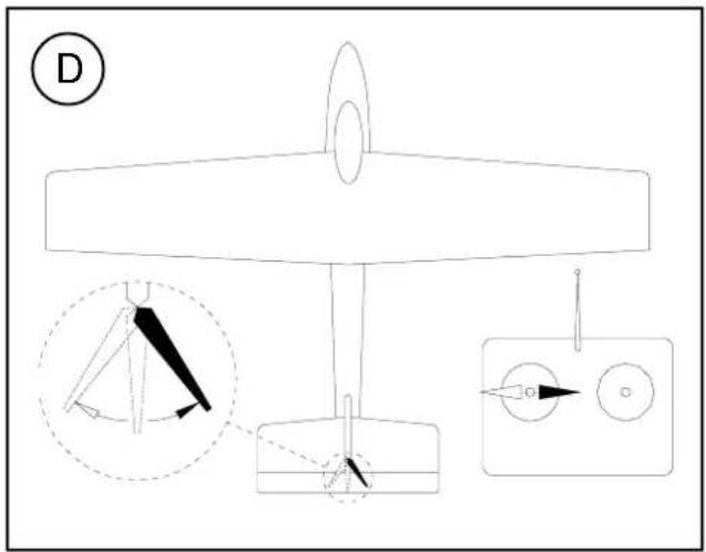
text_image
D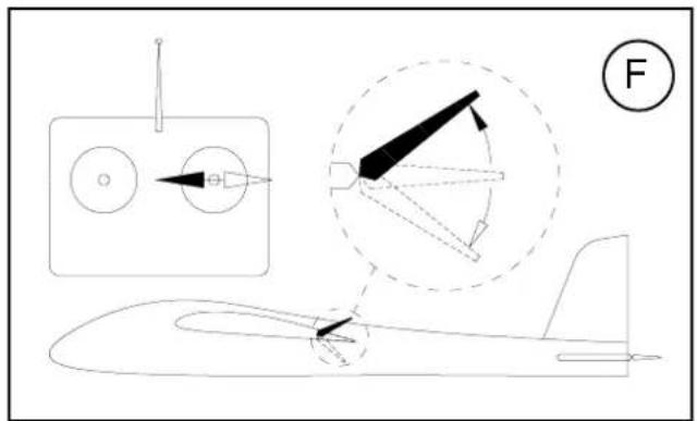
text_image
Technical diagram of an aircraft with labeled components and a force indicator (F)Basic information relating to model aircraft
natural_image
Line drawing of a helicopter in flight with an arrow indicating speed and a black-and-white circle symbol at the bottom (no text or labels)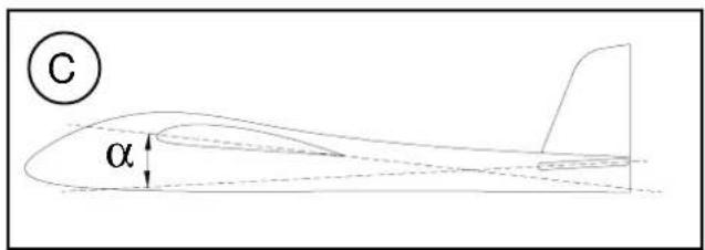
text_image
C α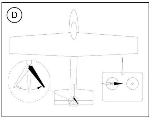
text_image
D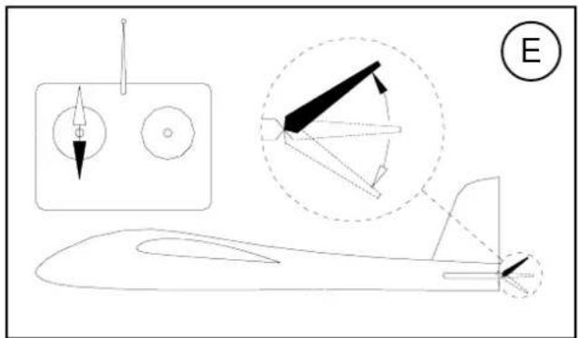
natural_image
Technical line drawing of a missile or aircraft with annotated components and an E symbol (no text or labels present)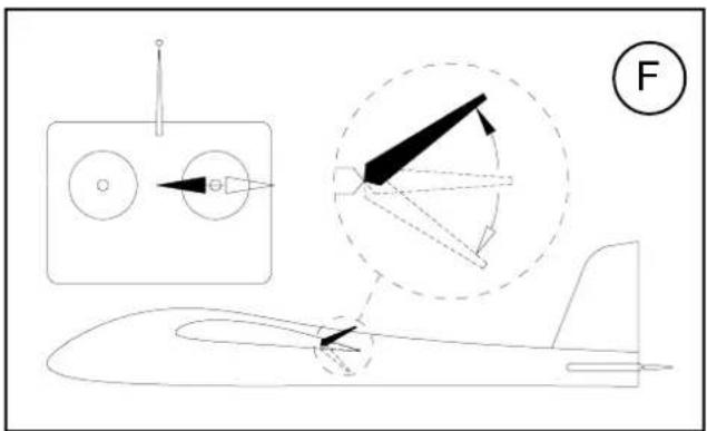
text_image
Diagram illustrating aircraft aerodynamics with labeled components and directional arrows, including a schematic view and a numbered circle.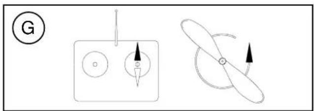
natural_image
Diagram showing two mechanical or electrical components: a circular component with pointer and a propeller-like shape with directional arrows (no text or symbols)# 22 4132
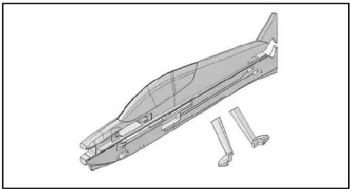
Rumpf mit Fahrwerksverkleidungen Fuselage and undercarriage fairings Fuselage avec habillage de roue Fusoliera con carenature carrello Fuselaje con revestimientos del tren de aterrizaje
natural_image
Technical line drawing of a mechanical component with multiple base parts and a separate view of a tool or bracket (no text or symbols present)# 22 4133
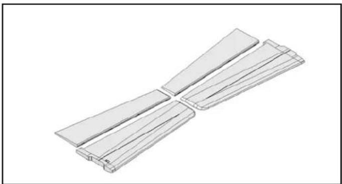
Tragflächen Wing panels Aile principale Semiali Alas
natural_image
Isometric view of two parallel rectangular metal profiles with cutouts, no text or symbols present# 22 4134
natural_image
3D technical illustration of a mechanical component with cutaway view (no text or symbols)# 22 4135
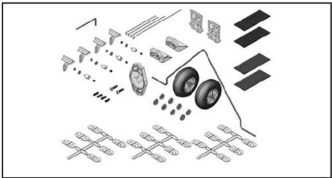
Kleinteile Tail set Petites pièces Minuteria Piezas pequeñas
text_image
Exploded view diagram of a vehicle's internal components and parts, including wheels, tires, and gear assembly# 22 4136
Draht- und Holmsatz
Wire and spar se
natural_image
Simple line drawing of a coiled wire or wire loop (no text or symbols)# 72 4501
Dekorbogen
Decal sheet
Starlock washer (pack of 10)
natural_image
Collection of ten circular mechanical washers arranged diagonally (no text or symbols visible)Kleber Empfehlung!
Recommended adhesive!
Colle conseillée!
Colla cnsigliata!
cola recomendada!
natural_image
Close-up of hands applying adhesive to a small bottle, alongside a bottle labeled 'ZM17 ELAPOR' (no visible text on the bottle itself)59 2727
Zacki ELAPOR