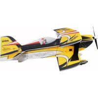
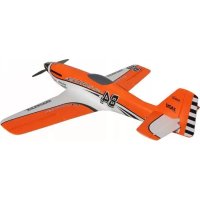
Kit+ Tucan - Remote control toy MULTIPLEX - Free user manual and instructions
Find the device manual for free Kit+ Tucan MULTIPLEX in PDF.

| Product type | Radio-controlled model airplane (kit) |
| Brand | Multiplex |
| Model | Kit+ Tucan |
| Wingspan | 1300 mm |
| Overall length | 1110 mm |
| Flight weight | 1850 g |
| Main materials | ELAPOR foam, birch plywood, plastic, metal |
| RC functions | Rudder, elevator, ailerons, motor, steerable nose wheel, optional retractable landing gear |
| Maximum speed | 130 km/h (standard), 165 km/h (tuning) |
| Flight duration | 8 to 10 minutes |
| Power supply | Li-BATT FX 3/1-2300 (M6) or 5/1-3200 (M6) battery |
| Motor | Brushless (included in power set) |
| Included servos | 4x Tiny S (UNI), 1x Tiny MG (UNI) |
| Receiver | RX-6-DR light M-LINK 2.4 GHz |
| Transmitter | SMART SX M-LINK |
| Charger | MULTIcharger L-703 EQU |
| Minimum age | 14 years (adult supervision) |
| Assembly | Kit requires cyanoacrylate glue, basic tools |
| Included accessories | Decal sheets, hex keys, small parts, fixed landing gear |
| Options | Retractable landing gear, MULTIlight lighting, pilot figure |
| Cleaning | Use a soft dry cloth; avoid harsh chemicals |
| Warranty | Defective or missing parts replaced after inspection |
Frequently Asked Questions - Kit+ Tucan MULTIPLEX
User questions about Kit+ Tucan MULTIPLEX
0 question about this device. Answer the ones you know or ask your own.
Ask a new question about this device
Download the instructions for your Remote control toy in PDF format for free! Find your manual Kit+ Tucan - MULTIPLEX and take your electronic device back in hand. On this page are published all the documents necessary for the use of your device. Kit+ Tucan by MULTIPLEX.
USER MANUAL Kit+ Tucan MULTIPLEX
20. Kabinenahaube (pic. 43-47)
This model is NOT A TOY in the usual sense of the term.
By operating the model the owner affirms that he is aware of the content of the operating instructions, especially those sections which concern safety, maintenance, operating restrictions and faults, and is capable of fulfilling these requirements.
This model must not be operated by any child under fourteen years of age. If a person below this age operates the model under the supervision of a competent adult who is acting as the child's guardian within the legal sense of the term, this individual is responsible for the implementation of the information in the OPERATING INSTRUCTIONS.
THE MODEL AND ASSOCIATED ACCESSORIES MUST BE KEPT OUT OF THE REACH OF CHILDREN UNDER THREE YEARS OF AGE! MODELS CONTAIN SMALL DETACHABLE PARTS WHICH MAY BE SWALLOWED BY CHILDREN UNDER THREE YEARS. CHOKING HAZARD!
All the warnings in the OPERATING INSTRUCTIONS must be observed whenever the model is operated. Multiplex Modellsport GmbH & Co. KG accepts no liability for loss or damage or any kind which occurs as a result of incorrect operation or misuse of this product, including the accessories required for its operation. This includes direct, indirect, deliberate and accidental loss and damage, and all forms of consequent damage.
Every safety note in these instructions must always be observed, as all the information contributes to the safe operation of your model. Use your model thoughtfully and cautiously, and it will give you and your spectators many hours of pleasure without constituting a hazard. Failure to operate your model in a responsible manner may result in significant property damage and severe personal injury. You alone bear the responsibility for the implementation of the operating instructions and the safety notes.
Approved usage
The model is approved exclusively for use within the modelling hobby. It is prohibited to use the model for any other purpose than that stated. The operator of the model, and not the manufacturer, is responsible for damage or injury of any kind resulting from non-approved use.
The model may only be operated in conjunction with those accessories which we expressly recommend. The recommended components have undergone thorough testing, are an accurate match to the model, and ensure that it functions safely. If you use other components, or modify the model, you operate it at your own risk, and any claim under guarantee is invalidated.
To minimise the risk when operating the model, please observe the following points:
- The model is guided using a radio control system. No radio control system is immune to radio interference, and such interference may result in loss of control of the model for a period of time. To avoid collisions, you must therefore ensure at all times that there is a wide margin of safety in all directions when operating your model. At the slightest sign of radio interference you must cease operating your model!
- Never operate your model until you have successfully completed a thorough check of the working systems, and carried out a range-check as stipulated in the instructions supplied with your transmitter.
- The model may only be flown in conditions of good visibility. You can avoid being temporarily blinded by not flying towards the sun, or in other diffi cult light conditions.
- A model must never be operated by a person who is under the influence of alcohol, drugs or medication which have an adverse effect on visual acuity and reaction time.
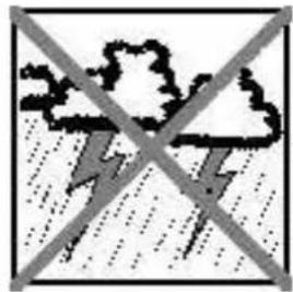
- Only fly your model in conditions of wind and weather in which you are able to maintain full control of the model. Even when the wind is light, bear in mind that turbulence can form at and around objects which may have an effect on the model.
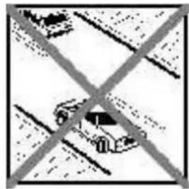
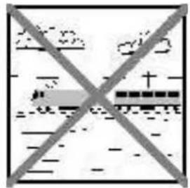
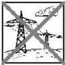
- Never fly in any location where you may endanger yourself of others, e.g. close to residential areas, overhead cables, open roads and railway lines.
- Never fly towards people or animals. You may think that flying low over other people's heads is proof of your piloting skill, but all it does is place others at unnecessary risk. It is in all our interests that you let other pilots know that this is what you think. Always fly in such a way that you do not endanger yourself or others. Bear in mind that even the best RC system in the world is subject to outside interference. No matter how many years of accident-free flying you have under your belt, you have no idea what will happen in the next minute.
Residual risks
Even if the model is operated in the correct manner, and you observe all safety aspects, there is always a certain residual risk.
For this reason it is mandatory to take out third-party liability insurance. If you join a club or flying association, insurance is usually available or included in the annual fee. Make sure that your insurance cover is adequate (i.e. that it covers powered model aircraft). Always keep your models and your radio control equipment in perfect order.
The following hazards may occur owing to the model's construction and type:
- Injury caused by the propeller: you must keep well clear of the area around the propeller from the moment that the battery is connected. Please bear in mind that objects in front of the propeller may be sucked into it, and objects behind the propeller may be blown away by it. The model may start moving when the propeller starts to turn. You must therefore position the model in such a way that it cannot move towards other persons if the motor should unexpectedly start running. When you are carrying out adjustment work involving the running motor, you must ensure that the model is always held securely by an assistant.
- Crash caused by pilot error: this can happen even to the best of pilots, so it is essential to fly exclusively in a safe environment; an approved model fl wing site and suitable insurance are basic essentials.
- Crash caused by technical failure or unnoticed damage in transit or in the workshop. A thorough check of the model before every flight is essential. However, you should also take into account at all times that material failures can and do occur. Never fly in a location where your model may damage or injure others.
- Keep within the stated operating limits. Excessively violent flying will weaken the airframe, and may result in sudden material failure, or may cause the model to crash during a subsequent flight due to "creeping" consequent damage.
- Fire hazard caused by electronic failure or malfunction. Store batteries safely, and always observe safety notes which apply to the airborne electronic components, the battery and the battery charger. Protect all electronic equipment from damp. Ensure that the speed controller and battery are adequately cooled.
The instructions which accompany our products must not be reproduced and / or published, in full or in part, in print or any electronic medium, without the express written approval of Multiplex Modellsport GmbH & Co. KG.
MULTIPLEX model kits are subject to constant quality checks throughout the production process, and we sincerely hope that you are completely satisfied with the contents of your kit. However, we would ask you to check all the parts before you start construction, as we cannot exchange components which you have already worked on. If you find any part is not acceptable for any reason, we will readily correct or exchange it. Just send the component to our Model Department. Please be sure to include the purchase receipt and a brief description of the fault.
We are constantly working on improving our models, and for this reason we must reserve the right to change the kit contents in terms of shape or dimensions of parts, technology, materials and fittings, without prior notification. Please understand that we cannot entertain claims against us if the kit contents do not agree in every respect with the instructions and the illustrations.
Caution!
Radio-controlled models, and especially model aircraft, are by no means playthings. Building and operating them safely requires a certain level of technical competence and manual skill, together with discipline and a responsible attitude at the flying field. Errors and carelessness in building and flying the model can result in serious personal injury and damage to property. Since we, as manufacturers, have no control over the construction, maintenance and operation of our products, we are obliged to take this opportunity to point out these hazards and to emphasise your personal responsibility.
Warning:
Like every aeroplane, this model has static limits. Steep dives and senseless manoeuvres inappropriate to the type may result in the loss of the aircraft. Please note: we will not replace the model in such cases. It is your responsibility to approach the airframe's limits gradually. It is designed for the power system recommended in these instructions, but is only capable of withstanding the flight loads if built exactly as described and if it is in an undamaged state.
Recommended equipment:
| Zacki ELAPOR 20g OrderNo. 85 2727 | |||
| Zacki ELAPOR super liquid 10g OrderNo. 85 2728 | |||
| Drive set „Tucan/ Mentor" Li-BATT powered | OrderNo. | 33 3663 | |
| or Drive set „Tucan/ Mentor" | OrderNo. | 33 2663 | |
| Battery Li-BATT FX 3/1-3200 (M6 | OrderNo. | 15 7371 | |
| 4x Servo Tiny S | OrderNo. | 6 5121 | |
| 1x Servo Tiny S MG | OrderNo. | 6 5122 | |
| 4x Extension lead 30 cm (UNI) | OrderNo. | 8 5031 | |
| Receiver RX-6-DR light M-LINK 2.4 GHz | OrderNo. | 8 5809 | |
| Transmitter SMART SX M-LINK | OrderNo. | 1 5300/1 | |
| Charger 230V MULTicharger L-703 EQU | OrderNo. | 8 2523 | |
Optional equipment:
| Drive set „TUCAN-TUNING S-BEC“ Li-BATT powered | OrderNo. | 33 3664 | ||
| or Drive set „TUCAN TUNING S-BEC“ | OrderNo. | 33 2664 | ||
| Battery Li-BATT FX 5/1-3200 (M6) | OrderNo. | 15 7373 | ||
| 4x Servo Tiny MG | OrderNo. | 6 5122 | ||
| 1x Servo HS-85MG | OrderNo. | 11 2086 | ||
| Retractable landing gear (Tucan) | OrderNo. | 72 3485 | ||
| Receiver RX-7 M-LINK 2,4 GHz | OrderNo. | 5 5818 | ||
| MULTIlight, 5 LEDs | OrderNo. | 7 3020 | ||
| Current sensor 35 A for receivers M-LINK | OrderNo. | 8 5404 | ||
| Pilot figure Johnny (orange) | OrderNo. | 73 3352 | ||
| Pilot figure Jimmy (blue) | OrderNo. | 73 3351 | ||
| Transmitter COCKPITSX | OrderNo. | 45 130/1/2 | ||
| Combo MULTlcharger LN-3008 EQU w.Mains PSU, AC/DC 230V/12V 5,0A | OrderNo. | 9 2545 | ||
| Charge lead w. high current plug (M6) | OrderNo. | 9 2516 | ||
Important note
This model is not made of Styrofoam™, and it is not possible to glue the material using white glue, polyurethane or epoxy; these adhesives only produce superficial joints, and simply break away under stress. Please be sure to use medium-viscosity cyano-acrylate glue exclusively, preferably Zacki ELAPOR® # 59 2727, which is optimised specifically for ELAPOR® particle foam. If you see Zacki ELAPOR® there is usually no need for cyano 'kicker' or activator. However, if you wish to use a different adhesive which requires the use of activator, please note that these materials are injurious to health, and should always be applied in the open air. Take care when handling all cyano-acrylate adhesives, as they harden in seconds, so don't get them on your fingers or other parts of the body. We strongly recommend the use of goggles to protect your eyes. Keep the adhesive out of the reach of children! For certain joints it is also possible to use hot-melt adhesive; the instructions indicate where this is the case.
Working with Zacki ELAPOR®
Zacki ELAPOR® has been developed specifically for glued joints in our models which consist of moulded ELAPOR® foam parts.
Please observe the following points in order to obtain perfect joints:
- Avoid the use of activator. 'Kicker' significantly weakens the joint. We advise leaving joined parts for 24 hours to obtain maximum strength, particularly when the glued area is large.
- Activator should only be used for temporary, small-area joints ('tacking'). Spray a little activator on one surface, and allow it to air-dry for about thirty seconds.
To obtain maximum joint strength you should lightly sand the surface with 320-grit abrasive paper before applying glue.
Bent parts - actually don't exist. If you find that a component has taken up a curve, perhaps after being transported, it is easy to straighten again. In this respect ELAPOR® behaves in a similar way to metal: bend the component back slightly beyond the correct position, and the material will then spring back to its proper shape when released, and maintain it. There are limits, however - don't overdo it!
Bent parts - really do exist. If you wish to paint your model, apply MPX Primer # 60 2700 to the surfaces, wiping it on very lightly as if you were cleaning the model. Paint must always be applied thinly and evenly, otherwise the component will warp. Then you really will have bent parts, and they will also be heavy and perhaps even unusable. We have found that matt-fi nish paints produce the best visual effect.
Technical information Tucan
Wingspan 1300 mm
Overall length 1110 mm
All-up weight 1850 g
Wing loading 58g / dm^2
RC Functions Rud., elev., aill.,throttle, controllable nose gear, optional retractable landing gear Topspeed: about 130 Km/h with standard drive set / 165 Km/h with tuning drive set
Time of flight: ca. 8-10 min
Note: please remove the pictures from the center of the instructions!
1. Preparations for building the model
To build the Tucan you will need a clean, perfectly fl at table or building board. The following tools are required: sharp balsa knife, medium-sized cross-point screwdriver, pointed-nose pliers, side-cutters, Lexan shears or nail scissors, abrasive paper (220 - 240-grit), 1.5mm & 2.5mm A/F allen key (supplied in the kit), and a hot-glue gun.
Unless stated otherwise, we recommend Zacki ELAPOR, # 85 2727, for all general joints on the model. You will also need Zacki ELAPOR super liquid, # 85 2728, and hot-melt glue for specific areas.
2. Installing the noseleg mounting (pic. 05)
Glue the noseleg mounting 15 to the reinforcements 16 & 17 as shown, taking care to line up the holes accurately. We recommend Zacki Elapor, #852727, for this.
3. Assembling the M-frame (internal wooden box incorporating mountings for the motor, flight battery and undercarriage) (pic. 06-09)
Place the following parts in the left-hand fuselage shell 5: nose bulkhead 18, side panel 19, reinforcement 20, bottom panel 21, former 22, transverse former 23 and reinforcement 24, together with parts 15, 16 and 17, which you have already assembled. Carefully tack the parts together, but without gluing them to the foam.
The reference lines in the illustration are intended as a guide here.
Once you have temporarily glued the frame parts together, remove the assembly from the foam shell and apply thin Zacki ELAPOR super liquid, # 59 2728, along the joints to reinforce them: simply run the adhesive along the joint lines where the parts meet, and allow it to flow between them.
Place the side panel 25 and the reinforcement 26 in the right-hand fuselage shell 6. Align the parts accurately, and carefully tack them to the assembly you have just prepared, but again taking care not to glue the parts to the foam.
- Remove the frame from the foam shell and apply Zack ELAPOR super liquid along the joints as described earlier. Carefully remove all excess glue residues.
Position the reinforcing components 29 and 30 on the rear of the motor mount. Ensure that the holes line up accurately, then glue the parts together.
4. Attaching the motor mount assembly (pic. 10)
Glue the washers 54 (12 mm O.D., 3.2 mm I.D.) to both sides of the nose bulkhead 18 at the positions shown, then attach the aluminium stand-off pillars 56 to the front using the four socket-head cheesehead screws 53 (M3 x 16 mm).
Apply a drop of thread-lock fl uid to each of the screws to prevent them working loose. If you have no thread-lock fl uid nail varnish is a useful alternative.
5. Joining the fuselage shells (pic. 11)
Position the assembled M-frame in the right-hand fuselage side, check that it is accurately aligned, and glue it to the foam shell. Allow the adhesive to set hard, then glue the two fuselage shells together.
The reference lines in the illustration are intended as a guide here. Take care to keep the fuselage perfectly straight, i.e. it must not be twisted or curved.
6. Preparing the control surface horns (pic. 12)
Insert the pushrod connector barrel 40 in the plastic control surface horn 38. Fit the brass M2 washer 41 and the brass M2 nut 42 on the threaded spigot, then tighten the nut using a small pair of pliers, but only just to the point where the connector barrel still rotates smoothly. Apply a drop of Zacki to secure the nut to the spigot. Fit the M3 x 3 mm socket-head grubscrew 39 in the threaded hole to a depth of about three full turns.
7. Completing the tailplane and elevator (pic. 13 & 14)
Locate the two GRP rods 73 (1.3 mm × 510mm and cut them to a length of 480~mm . Squeeze the tip of the (opened) Zacki bottle to a fl at shape with a pair of pliers, and use it to apply glue to the channels in the tailplane 10. Carefully press the two GRP rods 73 in the channels. Glue the elevator joiner 27 in the appropriate recess, and finally glue the prepared horn 38 in the elevator 10.
Cut through the elevators at the ends to allow them to deflect. Move the elevators up and down to free up the hinges, but take care not to deflect them too far - on no account separate the elevators from the tailplane!
8. Completing the fin and rudder (pic. 15)
Assemble the rudder horn 38 as described in Step 7, and glue it in the recess in the rudder 11.
KiCut through the rudder 11 at the top to release it. Move the rudder from side to side to free up the hinge line, but take care not to deflect it too far - on no account separate the rudder from the fin!
Carefully remove the exhaust pipes, which are moulded as part of the tailplane, taking care to cut them off fl ush; be sure to follow the separation lines shown in the drawing.
The distance between the separation line and the fin is 3 mm, and the correct cut will leave a 3 mm tongue attached to the tailplane.
9. Gluing the tailplane and fin to the fuselage (pic. 16 & 17)
- Position the tailplane 10 on the fuselage, and glue it in place.
- Check that it is exactly horizontal.
Position the fin 11 on the fuselage, and glue it in place. Check that it is exactly at right-angles to the tailplane.
10. Installing the tail servos (pic. 18 & 19)
Connect a 30 cm long servo extension lead, #8 5031, to the Tiny-S rudder servo, #6 5121, and tape the Uni connectors to prevent them working loose. Cut down the servo output lever to the length shown in Fig. 18, and thread the rudder pushrod 47 (1.5 Ø x 80 mm) through the servo output arm using the hole shown. Feed the servo lead through the duct in the fuselage, and place the rudder servo - with pushrod attached - in the appropriate recess. Check from the transmitter that the servo is at centre, then fix it to the foam by applying hot-melt glue to the mounting lugs. Set the rudder to centre (neutral), and tighten the grubscrew in the barrel connector. Tighten the servo output screw to secure the output arm.
11. Preparing the wing retainer system (pic. 20 & 21)
Glue the circular plywood discs 33 to the transverse plate 32, then press the captive nut 44 (M6 x 8 mm) into the hole from the underside; you may need to tap it into place with a hammer. Secure the nut with adhesive.
Glue the two side pieces 31 to the sub-assembly you have just prepared.
12. Gluing the wing retainer system to the wing centre section (pic. 22 & 23)
Place the wing retainer assembly in the top of the wing centre section 9, position it accurately, and glue it in place. Glue the former 35 to the foam part.
Slide the CFRP tube 72 (8 × 370mm into the foam part from the side, and pass it through the openings in the wing retainer assembly. The tube should end flush at both sides. Glue it in the correct position, applying adhesive to the whole surface.
13. Gluing the outboard wing panels to the centre section (pic. 24)
Apply adhesive to the mating surfaces. Place the right-hand outboard wing panel 8 on the centre section 9 from above, and position it carefully. It is a good idea to spray a little activator on the surfaces to ensure that the joints cure quickly. Repeat this procedure with the left-hand outboard wing panel 7.
14. Gluing the spars to the wings (pic. 25)
Cut down two GRP rods 73 (1.3 Ø x 510 mm) to a length of 480 mm. Glue one part 73 and one CFRP tube 71 (8 Ø x 470 mm) in the appropriate channels in the underside of each wing panel.
Note:
Lay each wing panel down fl at when working on it, to avoid warps.
15. Completing the ailerons (pic. 26 & 12)
Prepare two aileron horns 38 as described in Step 7; take care to produce a handed (mirror-image) pair, as shown in Fig. 12. Glue the horns 38 in the recesses in the underside of the aileron of each wing panel.
Cut through the ailerons at each end to release them. Move the ailerons up and down to free up the hinges, but take care not to deflect them too far - on no account separate the ailerons from the wings!
16. Installing the wing-mounted servos (pic. 26)
Cut down the output arms of the Tiny-S servos, # 6 5121, as shown in Fig. 26. Connect the aileron pushrods 46 (1 Ø x 50 mm) to the output arms, and fi t the servos in the outboard wing panels 7 and 8. Check from the transmitter that the servos are at centre, then fi x them to the foam by applying hot-melt glue to the mounting lugs. Connect a 30 cm long servo extension lead, # 8 5031, to each servo. Finally set the ailerons to centre (neutral), and tighten the grubscrews in the barrel connectors.
17. Installing the undercarriage mountings (pic. 27 & 28)
Glue the undercarriage mount 36 to the reinforcements 34 as shown in Fig. 27 to produce the mounting for the right-hand undercarriage unit; check that the holes line up accurately.
Repeat this procedure for the left-hand side, using the plywood parts 36 and 2 × 34 . It is important to produce two mirror-image sub-assemblies (different left and right).
Place the right-hand undercarriage mounting in the appropriate opening, position it carefully, and glue it in place. Repeat this procedure with the left-hand wing panel.
18. Installing the fixed main undercarriage (included in the kit) (pic. 29-33)
All the parts required for this stage can be found in the bag marked "Tucan undercarriage set".
Drill a hole of around 4.5mm at the points marked L and R in the plastic main undercarriage brackets 62. Slide the wire main undercarriage legs 58 & 59 through the brackets from the underside, and screw these assemblies to the covers 63 using the self-tapping screws 67 (2.9× 9.5) The undercarriage assemblies can now be installed in the outboard wing panels 7 and 8 as shown in the illustrations, using the self-tapping screws 67 (2.9× 9.5)
Screw an M3 x 3 socket-head grubscrew into each collet 68 (4 mm) to a depth of about three full turns. Slip one collet 68 / 69 onto each wheel leg, followed by a wheel 61 and another collet 68 / 69. Position the collets in such a way that the wheels rotate smoothly and freely, then tighten the socket-head grubscrews firmly.
- Installing the steerable fixed noseleg unit (included in the kit) (pic. 34-42)
Slip one collet 68 / 69 onto the noseleg. Now slip the wheel leg through the hole in the noseleg bracket 64, and fit a second collet 68 / 69 on it, followed by the steering arm 65. Tighten the grubscrews in the collets at this point, as shown in Fig. 37: ensure that the steering arm is parallel to the wheel axle, and that the nosewheel leg is free to swivel smoothly.
Install the nosewheel using the same procedure as described for the main undercarriage wheels. Slip the nosewheel steering pushrod 70 (1.5 Ø x 151 mm) into the outermost hole in the steering arm 65, and thread this assembly into the fuselage, as shown in Fig. 40. Finally screw the complete nosewheel bracket assembly 64 in place using the self-tapping screws 66 (3.0 x 16).
Remove the output lever from the Tiny-MG nosewheel steering servo, # 6 5122, place the servo on the left-hand side of the forward fuselage in the position shown, and secure it by applying hot-melt adhesive to the mounting lugs and the side of the servo. Drill a 1.5mm hole in the servo output arm in the position shown, then fit a swivel pushrod connector 40 through the hole from the underside. Fit a brass M2 washer 41 and a brass M2 nut 42 on the threaded spigot and tighten the nut just to the point where the connector swivels smoothly. Secure the nut to the spigot with a drop of glue. Set the servo to neutral from the transmitter, centre the nosewheel, then tighten the M3 x 3 socket-head grubscrew 69, working through the bottom opening in the fuselage.
Note!
The nut retaining the swivel pushrod connector must not foul the servo case; if it does, reduce the servo travel slightly at the transmitter.
20. Canopy (pic. 43-47)
Glue the magnetic canopy latch component 45 (the thicker part) in the fuselage, setting it flush with the surface.
Glue the canopy retainer 28 in the recess in the front part of the cockpit cradle 12.
If you wish to add detail to the cockpit, we recommend that you paint it grey using ELAPOR-Color, # 60 2722. Suitable stickers for cockpit instruments and seats are supplied in the kit (decal sheet A). If you wish, you can glue the optional pilot fi gures # 73 3351 and # 73 3352 in the cockpit. Roughen the base of the pilot fi gures and remove all traces of grease before gluing them in place.
Cut out the canopy 14 along the marked lines. Lexan shears are particularly good for cutting out the moulding, but nail scissors are a good alternative.
The next step is to glue the canopy 14 to the cockpit cradle 12; this is the procedure: place the cockpit cradle on the fuselage and apply very small dots of adhesive to the frame, spaced about 8cm apart. Now place the canopy on the frame, and carefully press it into contact with the adhesive.
Allow the glue to set for about ten minutes before removing it from the fuselage again. Complete the job by applying high-quality adhesive tape, e.g. insulating tape, all round the edge of the canopy.
Place the magnetic latch component 45 (the thinner part) on its counterpart (already glued in the fuselage), align it with the fuselage centreline, and spray a little activator on it. Apply a drop of cyano to the point on the canopy where the magnetic latch will make contact, then press the canopy onto the fuselage. This ensures that both halves of the canopy latch magnets line up correctly, and the canopy will be held securely.
21. Installing the power system (pic. 48 & 52)
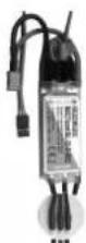
Screw the motor to the aluminium motor bulkhead 56 using four of the M3 x 10 mm screws included in the power set. Locate the three wires attached to the speed controller and connect them to the motor wires. Thread this assembly into the fuselage from the front, and screw the motor bulkhead to the aluminium stand-off pillars 56 using four socket-head screws 53 (M3 x 16 mm).
Attach the speed controller to the inside of the fuselage using Velcro (hook-and-tape) tape 48 and 49, in the position shown in Fig. 52. Since the Velcro tape sticks to itself of very strongly, we recommend that you apply a few drops of Zacki to the adhesive side of the tape to prevent it being torn from the fuselage.
Note!
Check the direction of rotation of the motor: when viewed from the front, the motor shaft must rotate anti-clockwise. Carry out this check before fitting the propeller to the motor.
22. Installing the propeller (pic. 49 & 50)
Carefully balance the propeller. Unscrew the nut from the propeller driver 57, and slip the propeller on it, followed by the plastic spinner backplate 52. Screw the nut on the propeller driver once more, slide this assembly onto the motor shaft, and tighten the nut fully. Push the Elapor spinner 13 onto the spinner backplate 52.
Note! We recommend the MPX propeller balancer, # 33 2355, for balancing the propeller.
23. Installing the exhaust pipes (pic. 51)
- Locate the exhaust pipes which you earlier separated from the fin 11, and offer them up to the appropriate recesses on both sides of the fuselage. Position them carefully, and glue them in place.
24. Installing the receiver (pic. 52)
Fix the receiver in the position shown using a piece of the Velcro tape 48 and 49 supplied in the kit.
25. Final assembly of the model
Thread the Velcro tape 50 once through the bottom of the M-frame in the fuselage, forward of the wing retaining screw, and position it in such a way that it projects by the same length on both sides. Fix the Velcro in place with a drop of Zacki Elapor. Attach the wing to the fuselage using the plastic retaining screw 43. Decorate the model by applying the decals supplied in the kit. Alternatively you can paint it in the scheme of your choice using ELAPOR color paints.
26. Installing the flight battery, setting the correct Centre of Gravity
The battery should not be installed until the model can be completely assembled. Adjust the position of the battery on the battery tray until the model balances 90mm from the root leading edge of the wing, i.e. measured at the fuselage, without requiring lead ballast. You will find it easier to balance the model if you hold it inverted. Use a piece of Velcro to prevent the battery slipping out of position.
27. Setting the control surface travels
Set the control surface travels as follows:
Ailerons: 15 / 12mm ± 20% Expo
Elevator: 10 / 8 ~mm ± 20% Expo
Rudder: 15 / 15 ~mm ± 10% Expo
Nosewheel: 8 / 8 ~mm ±
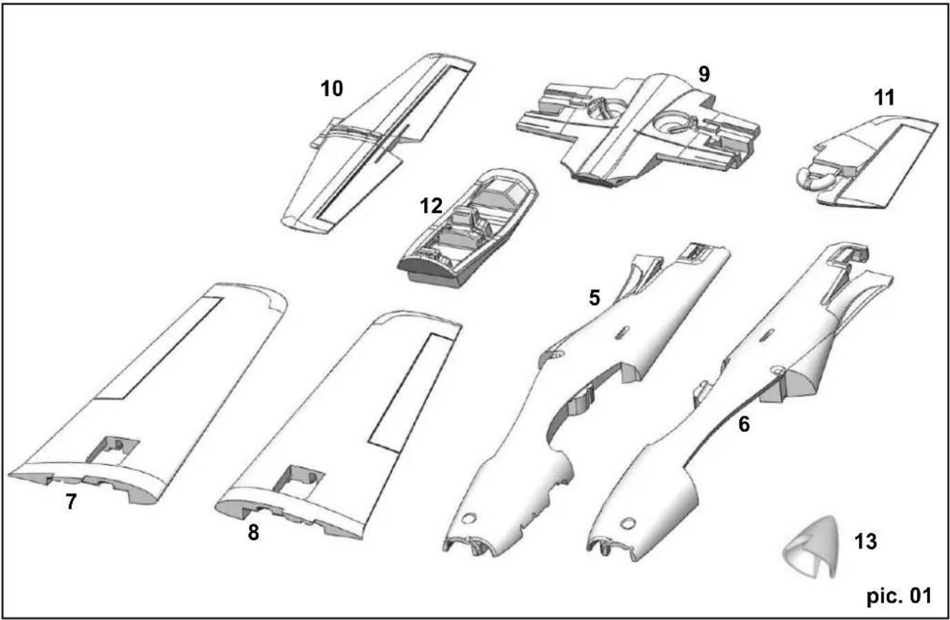
Part Number Qty Description Material Dimensions
1 1 Tucan building instructions Paper DIN A4
2 1 Model complaint form Paper DIN A5
3 1 Tucan decal sheet A (top) Printed fi Im
4 1 Tucan decal sheet B (bot.) Printed fi Im
Foam parts
5 1 Tucan L.H. fuselage shell Moulded Elapor Ready made
6 1 Tucan R.H. fuselage shell Moulded Elapor Ready made
7 1 Tucan L.H. wing panel Moulded Elapor Ready made
8 1 Tucan R.H. wing panel Moulded Elapor Ready made
9 1 Tucan wing centre section Moulded Elapor Ready made
10 1 Tucan tailplane Moulded Elapor Ready made
11 Tucan fin Moulded Elapor Ready made
12 1 Tucan cockpit cradle Moulded Elapor Ready made
13 1 Tucan Elapor spinner Moulded Elapor 60 mm, 63 mm
14 1 Tucan canopy Plastic Ready made
Wooden parts - fuselage
15 1 Noseleg mounting Birch plywood 3 mm
16 1 Reinforcement Birch plywood 3 mm
17 1 Reinforcement Birch plywood 3 mm
18 1 Nose bulkhead Birch plywood 3 mm
19 1 Side panel Birch plywood 3 mm
20 1 Reinforcement Birch plywood 3 mm
21 1 Bottom panel Birch plywood 3 mm
22 1 Former Birch plywood 3 mm
23 1 Transverse former Birch plywood 3 mm
24 1 Reinforcement Birch plywood 3 mm
25 1 Side panel Birch plywood 3 mm
26 1 Reinforcement Birch plywood 3 mm
27 1 Elevator joiner Birch plywood 3 mm
28 1 Canopy retainer Birch plywood 3 mm
29 1 Reinforcement Birch plywood 3 mm
30 1 Reinforcement Birch plywood 3 mm
Wooden parts - wings
31 2 Side piece Birch plywood 3 mm
32 1 Transverse plate Birch plywood 3 mm
33 2 Reinforcement Birch plywood 3 mm
34 4 Reinforcement Birch plywood 3 mm
35 1 Former Birch plywood 3 mm
36 2 Undercarriage mount Birch plywood 3 mm
37 2 Cover Birch plywood 1.5mm
Small parts set
38 4 Control surface horN Injection-moulded plastic
39 5 Socket-head grubscrew Metal M 3× 3
40 5 Swivel pushrod connector Aluminium 6 mm Ø
41 5 Washer Brass M2
42 5 Nut Brass M2
43 1 Plastic screw Nylon M6x25
44 1 Captive nut Plated metal M 6 x 8
45 1 Magnetic latch Metal Ready made
46 3 Spring steel wire with Z Metal 1 × 50mm
47 1 Spring steel wire with Z Metal 1 × 80mm
48 2 Hook-and-loop, tape, hook Plastic 25 × 60 ~mm
49 2 Hook-and-loop tape, loop Plastic 25 × 60 ~mm
50 1 Hook-and-loop tape „back to back" black / red 16 × 200 mm
51 1 Allen key Metal 1.5 A/F
51.1 1 Allen key Metal 2.5 A/F
52 1 Spinner backplate Plastic 26 mm Ø
53 8 Socket-head cheesehead screw M3 x 16
54 8 Washer Metal 12 mm, 3 mm
55 1 Tucan aluminium motor bulkhead Die-cut aluminium
56 4 Spacer pillar aluminium 6 0x54-2xM3
57 1 Elapor 5/6 driver with M6 hex. Nut with 5mm shaft/6mm bore
Undercarriage set
58 1 L.H. wheel leg Spring steel wire 4mm
59 1 R.H. wheel leg Spring steel wire 4mm
60 1 Nosewheel leg Spring steel wire 4mm
61 3 Airwheel with rubber tyre Plastic 57 mmØ/4.1mm
62 2 Main undercarriage bracket, R + L, Plastic Ready made 63 2 Main undercarriage cover, R + L, Plastic Ready made
64 1 Noseleg bracket Plastic Ready made
65 1 Nosewheel steering arm Plastic Ready made
66 4 Plated PT screw, 3.0 × 16 ~mm , cross-point Metal 3.0 × 16 ~mm
67 20 Self-tapping screw Metal 2.9× 9.5mm
68 8 Collet Metal 4 mm
69 8 Socket-head grubscrew Metal M3x3
70 1 Nosewheel pushrod, long, one Z-bend Metal 1.5 x 151 mm
Spars
71 2 CFRP tube, Carbon fibre reinforced plastic 8 × 5.4× 470mm
72 1 CFRP tube, Carbon fibre reinforced plastic 80 × 5.4 × 370 ~mm
73 4 GRP rod, Glass fibre reinforced plastic 1.3 x 510 mm
Additional items in KIT+
| 74 | 4 | UNI servo extension lead | Plastic / metal | 300 mm | |
| 75 | 1 | Tiny-MG (UNI) servo | Plastic / metal | 30 x 12 x 30 mm | |
| 76 | 4 | Tiny-S (UNI) servo | Plastic metal | 30 x 12 x 30 mm | |
| 77 | 1 | „Tucan“ power set, Li-BATT powered,Various | 374x128x63 mm | ||
Charge alaire: 58 g/dm
e 5. Collage du fuselage (pic. 11)
Derive: 15/15mm ± 10% Expo
Roulette de queue: 8 / 8mm ±
Rumpthalften/Fuselage shells/Fuselage
(1)
1 + u7 = 8
3.6 × 2
5.6 X2 Rumpf
15-30
(2)细胞壁:脑聚糖体
(2)细胞壁:脑聚糖体
BAC
224281
x > 2
2 = ①
Shakeproof was Rondelle dentee
Shakepr Rondelle
Rondelle dentée
Socket-head cheesehead screw Vis a tete cylindriques
Socket-head cheesehead screw Vis a tete cylindriques