RR StuntMaster - Remote control toy MULTIPLEX - Free user manual and instructions
Find the device manual for free RR StuntMaster MULTIPLEX in PDF.

User questions about RR StuntMaster MULTIPLEX
0 question about this device. Answer the ones you know or ask your own.
Ask a new question about this device
Download the instructions for your Remote control toy in PDF format for free! Find your manual RR StuntMaster - MULTIPLEX and take your electronic device back in hand. On this page are published all the documents necessary for the use of your device. RR StuntMaster by MULTIPLEX.
USER MANUAL RR StuntMaster MULTIPLEX
text_image
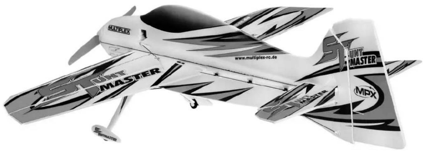
STUNT MASTER MULTIPLEX www.multiplex-rc.de MPX STUNT MASTER MUST MASTER SPENTMASTERD Bauanleitung 2 ... 8
GB Building instructions 9 ... 15
F Notice de construction 16 ... 30
I Instruzioni di montaggio 31 ... 37
ES Instrucciones de montaje 38 ... 44
Abbildungen
Illustrations
Illustrations
Illinstrazioni
liustraciones
Ersatzteile
Replacement parts
Pièces de rechanges
Parti di ricambio
Repuestos
45-47
natural_image
Crosshair pattern with diagonal lines and a vehicle silhouette (no text or symbols)
text_image
Prohibition sign with crossed-out lines and icons, featuring a train crossing over water and a cross symbol
natural_image
Symbolic illustration of transmission towers crossed out by a diagonal line, representing power or signal exclusion (no text present)
natural_image
Weather warning symbol with lightning and cloud over rain (no text)
Restrisiken
SR Option Seilanlenkung (pic. 17-22):
10 1 links Fahrwerksbein
14 1 Propeller GWS EP
15 2 Propeller-Adapterring
24 1 Ruderhorn QR links
This model is NOT A TOY in the usual sense of the term.
By operating the model the owner affirms that he is aware of the content of the operating instructions, especially those sections which concern safety, maintenance, operating restrictions and faults, and is capable of fulfilling these requirements.
This model must not be operated by any child under fourteen years of age. If a person below this age operates the model under the supervision of a competent adult who is acting as the child's guardian within the legal sense of the term, this individual is responsible for the implementation of the information in the OPERATING INSTRUCTIONS.
THE MODEL AND ASSOCIATED ACCESSORIES MUST BE KEPT OUT OF THE REACH OF CHILDREN UNDER THREE YEARS OF AGE! MODELS CONTAIN SMALL DETACHABLE PARTS WHICH MAY BE SWALLOWED BY CHILDREN UNDER THREE YEARS. CHOKING HAZARD!
All the warnings in the OPERATING INSTRUCTIONS must be observed whenever the model is operated. Multiplex Modellsport GmbH & Co. KG accepts no liability for loss or damage or any kind which occurs as a result of incorrect operation or misuse of this product, including the accessories required for its operation. This includes direct, indirect, deliberate and accidental loss and damage, and all forms of consequent damage.
Every safety note in these instructions must always be observed, as all the information contributes to the safe operation of your model. Use your model thoughtfully and cautiously, and it will give you and your spectators many hours of pleasure without constituting a hazard. Failure to operate your model in a responsible manner may result in significant property damage and severe personal injury. You alone bear the responsibility for the implementation of the operating instructions and the safety notes.
Approved usage
The model is approved exclusively for use within the modelling hobby. It is prohibited to use the model for any other purpose than that stated. The operator of the model, and not the manufacturer, is responsible for damage or injury of any kind resulting from non-approved use.
The model may only be operated in conjunction with those accessories which we expressly recommend. The recommended components have undergone thorough testing, are an accurate match to the model, and ensure that it functions safely. If you use other components, or modify the model, you operate it at your own risk, and any claim under guarantee is invalidated.
To minimise the risk when operating the model, please observe the following points:
- The model is guided using a radio control system. No radio control system is immune to radio interference, and such interference may result in loss of control of the model for a period of time. To avoid collisions, you must therefore ensure at all times that there is a wide margin of safety in all directions when operating your model. At the slightest sign of radio interference you must cease operating your model!
- Never operate your model until you have successfully completed a thorough check of the working systems, and carried out a range-check as stipulated in the instructions supplied with your transmitter.
- The model may only be flown in conditions of good visibility. You can avoid being temporarily blinded by not flying towards the sun, or in other difficult light conditions.
- A model must never be operated by a person who is under the influence of alcohol, drugs or medication which have an adverse effect on visual acuity and reaction time.
- Only fly your model in conditions of wind and weather in which you are able to maintain full control of the model. Even when the wind is light, bear in mind that turbulence can form at and around objects which may have an effect on the model.
- Never fly in any location where you may endanger yourself of others, e.g. close to residential areas, overhead cables, open roads and railway lines.
- Never fly towards people or animals. You may think that flying low over other people's heads is proof of your piloting skill, but all it does is place others at unnecessary risk. It is in all our interests that you let other pilots know that this is what you think. Always fly in such a way that you do not endanger yourself or others. Bear in mind that even the best RC system in the world is subject to outside interference. No matter how many years of accident-free flying you have under your belt, you have no idea what will happen in the next minute.
natural_image
Cross-shaped diagram with a vehicle and road markings, no readable text or symbols
text_image
Prohibition sign with crossed-out lines and symbols, including a train crossing over water and a cross symbol
natural_image
Symbolic illustration of transmission towers crossed out, representing interference or exclusion (no text present)
natural_image
Weather warning symbol with lightning and cloud (no text)Residual risks
Even if the model is operated in the correct manner, and you observe all safety aspects, there is always a certain residual risk.
For this reason it is mandatory to take out third-party liability insurance. If you join a club or flying association, insurance is usually available or included in the annual fee. Make sure that your insurance cover is adequate (i.e. that it covers powered model aircraft). Always keep your models and your radio control equipment in perfect order.
The following hazards may occur owing to the model's construction and type:
- Injury caused by the propeller: you must keep well clear of the area around the propeller from the moment that the battery is connected. Please bear in mind that objects in front of the propeller may be sucked into it, and objects behind the propeller may be blown away by it. The model may start moving when the propeller starts to turn. You must therefore position the model in such a way that it cannot move towards other persons if the motor should unexpectedly start running. When you are carrying out adjustment work involving the running motor, you must ensure that the model is always held securely by an assistant.
- Crash caused by pilot error: this can happen even to the best of pilots, so it is essential to fly exclusively in a safe environment: an approved model fl ving site and suitable insurance are basic essentials.
- Crash caused by technical failure or unnoticed damage in transit or in the workshop. A thorough check of the model before every flight is essential. However, you should also take into account at all times that material failures can and do occur. Never fly in a location where your model may damage or injure others.
- Keep within the stated operating limits. Excessively violent flying will weaken the airframe, and may result in sudden material failure, or may cause the model to crash during a subsequent flight due to “creeping” consequent damage.
● Fire hazard caused by electronic failure or malfunction. Store batteries safely, and always observe safety notes which apply to the airborne electronic components, the battery and the battery charger. Protect all electronic equipment from damp. Ensure that the speed controller and battery are adequately cooled.
The instructions which accompany our products must not be reproduced and / or published, in full or in part, in print or any electronic medium, without the express written approval of Multiplex Modellsport GmbH & Co. KG.
MULTIPLEX model kits are subject to constant quality checks throughout the production process, and we sincerely hope that you are completely satisfied with the contents of your kit. However, we would ask you to check all the parts before you start construction, as we cannot exchange components which you have already worked on. If you find any part is not acceptable for any reason, we will readily correct or exchange it. Just send the component to our Model Department. Please be sure to include the purchase receipt and a brief description of the fault.
We are constantly working on improving our models, and for this reason we must reserve the right to change the kit contents in terms of shape or dimensions of parts, technology, materials and fittings, without prior notification. Please understand that we cannot entertain claims against us if the kit contents do not agree in every respect with the instructions and the illustrations.
Caution!
Radio-controlled models, and especially model aircraft, are by no means playthings. Building and operating them safely requires a certain level of technical competence and manual skill, together with discipline and a responsible attitude at the fl ying fi eld. Errors and carelessness in building and fl ying the model can result in serious personal injury and damage to property. Since we, as manufacturers, have no control over the construction, maintenance and operation of our products, we are obliged to take this opportunity to point out these hazards and to emphasise your personal responsibility.
Warning:
Like every aeroplane, this model has static limits. Steep dives and senseless manoeuvres inappropriate to the type may result in the loss of the aircraft. Please note: we will not replace the model in such cases. It is your responsibility to approach the airframe's limits gradually. It is designed for the power system recommended in these instructions, but is only capable of withstanding the flight loads if built exactly as described and if it is in an undamaged state.
Recommended equipment:
Zacki ELAPOR 20g VE1 Item number: 852727
Li-BATT FX 3/1-450 (M6) Item number: 157311
Receiver RX-5 light M-LINK 2,4 GHz Item number: 55808
COCKPIT SX M-LINK classic, transmitter 2,4 GHz Item number: 45130/1/2
Combo MULTicharger LN-3008 EQU w.Mains PSU, AC/DC 230V/12V 5,0A Item number: 92545
Charge lead w. high current plug (M6) Item number: 92516
Optional equipment:
Model-Service-Box
Item number: 85500
Important note
This model is not made of Styrofoam™, and it is not possible to glue the material using white glue, polyurethane or epoxy; these adhesives only produce superficial joints, and simply break away under stress. Please be sure to use medium-viscosity cyano-acrylate glue exclusively, preferably Zacki ELAPOR® # 59 2727, which is optimised specifically for ELAPOR® particle foam. If you see Zacki ELAPOR® there is usually no need for cyano ‘kicker’ or activator. However, if you wish to use a different adhesive which requires the use of activator, please note that these materials are injurious to health, and should always be applied in the open air. Take care when handling all cyano-acrylate adhesives, as they harden in seconds, so don’t get them on your fingers or other parts of the body. We strongly recommend the use of goggles to protect your eyes. Keep the adhesive out of the reach of children! For certain joints it is also possible to use hot-melt adhesive; the instructions indicate where this is the case.
Working with Zacki ELAPOR®
Zacki ELAPOR® has been developed specifi cally for glued joints in our models which consist of moulded ELAPOR® foam parts.
Please observe the following points in order to obtain perfect joints:
- Avoid the use of activator. ‘Kicker’ significantly weakens the joint. We advise leaving joined parts for 24 hours to obtain maximum strength, particularly when the glued area is large.
- Activator should only be used for temporary, small-area joints ('tacking'). Spray a little activator on one surface, and allow it to air-dry for about thirty seconds.
• To obtain maximum joint strength you should lightly sand the surface with 320-grit abrasive paper before applying glue.
Bent parts - actually don't exist. If you find that a component has taken up a curve, perhaps after being transported, it is easy to straighten again. In this respect ELAPOR® behaves in a similar way to metal: bend the component back slightly beyond the correct position, and the material will then spring back to its proper shape when released, and maintain it. There are limits, however - don't overdo it!
Bent parts - really do exist. If you wish to paint your model, apply MPX Primer # 60 2700 to the surfaces, wiping it on very lightly as if you were cleaning the model. Paint must always be applied thinly and evenly, otherwise the component will warp. Then you really will have bent parts, and they will also be heavy and perhaps even unusable. We have found that matt-fi nish paints produce the best visual effect.
Technical information STUNTMASTER:
Wingspan: 870 mm
Overall length: 928 mm
All-up weight: 350 g
Total surface area: 24 dm²
Wing loading: 14,6 g/dm²
Channels: 4
RC Functions: rudder, elevator, aileron, motor
Flight time: ca. 5 min (3S \~450 mAh)
Note: please remove the pictures from the center of the instructions!
Congratulations on your new STUNTMASTER!
Completing the model:
You will need the following tools to complete the model:
- Ruler or tape measure
- Small cross-point screwdriver
- Slot-head screwdriver (approx. 5 mm)
- Sharp balsa knife
- Pointed-nose pliers
• Zacki Elapor adhesive # 852727
Start by checking the kit components against the Parts List on page 15 (Fig. 01), to ensure that everything is present in the box.
1. Installing the undercarriage (Fig. 02):
Apply a drop of Zacki to each side of the fuselage 1, and push the two undercarriage legs 10 and 11 into the appropriate openings. Ensure that the fuselage is level when standing on the undercarriage.
2. Attaching the wing (Fig. 03):
Working from the right-hand side, slide the wing 2 half-way through the fuselage 1. Now apply a little Zacki to the central area of the wing, top and bottom.
→Tip: if you apply the glue only to the left-hand area of the wing centre section, the action of pushing the wing into place will distribute the adhesive over the whole joint surface.
Push the wing fully into the fuselage, checking immediately that the two components are exactly at right-angles to each other. It is essential that the wing is "square" to the fuselage, i.e. dimensions A and B must be identical. The wing must also be at right-angles to the fuselage when viewed from the nose or tail. If excess glue is squeezed out of the joint, wipe it off using a paper towel.
3. Attaching the tailplane (Fig. 4):
The procedure for fitting the tailplane 3 is similar to that for attaching the wing. Dimensions C and D must be identical. Once again, ensure that everything is "square".
4. Attaching the rudder (Figs. 5 & 6):
First glue the in-fi II piece 9 in the opening in the tail end of the fuselage 1. The hinges for the rudder 4 can now be glued in the prepared slots.
→Tip: to ensure that the adhesive actually enters the hinge slots without spilling out, compress the tip of the Zacki bottle slightly using pointed-nose or fl at-nose pliers, so that the exit opening is oval.
Take care to allow no more than a little adhesive to be squeezed out of the hinge slots, and maintain a gap about 1 mm wide between rudder and fin (rear edge of the fuselage
It is important that the rudder swivels freely and easily from one extreme to the other.
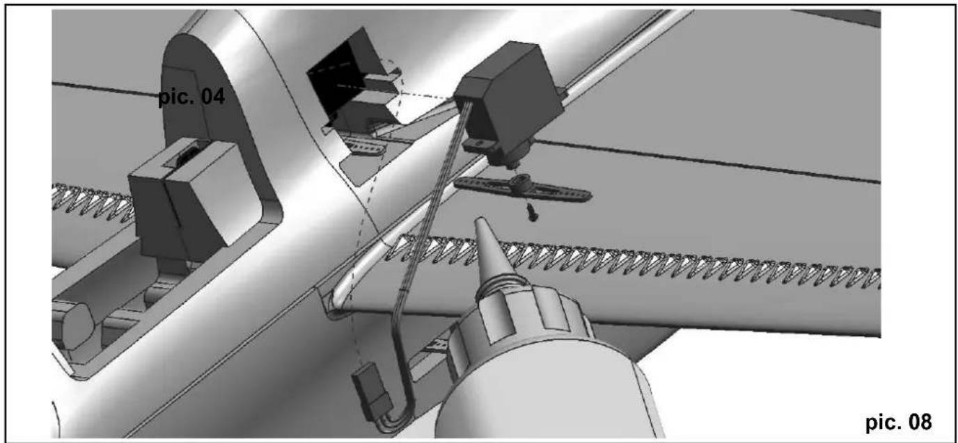
5. Installing the servos (Figs. 07 - 09):
First remove the battery hatch 7 from the fuselage 1.
Apply a little Zacki to the base of the horn 24 and glue it in the moulded-in recess in the left-hand aileron. Remove the aileron servo from its well, and set it to centre (neutral) from the transmitter. Fit the output lever on the servo output shaft, and tighten the retaining screw firmly. The servo can now be glued in the appropriate opening in the fuselage by applying a little Zacki at each mounting lug.
Repeat the procedure with the rudder and elevator servos.
Route all the servo leads through to the front fuselage compartment.
6. Installing the wing and tailplane braces (Figs. 10 - 12):
Glue the supports 5 and 6 to the underside of the wing at the marked points, then glue the braces 16 (front, approx. 1.3 x 300 mm) and 17 (rear, approx. 1.3 x 305 mm) in place as shown. It is important that the braces are not under tension when fitted, as this could introduce warps into the wing. Check that the wing is still at right-angles to the fuselage when viewed from the nose and tail. Fix the braces to the wing and fuselage, applying a small drop of Zacki to the transitions between the plastic and CFRP parts.
Use the same general procedure to install the tailplane braces 15 (approx. 1.5 x 130 mm).
7. Installing the control surface linkages (Figs. 13 - 22):
AILERONS:
Locate the clevises attached to the pushrods 18 (approx. 1.3 x 130), connect them to the outer holes in the aileron servo output lever, then slide the rubber sleeves over them to prevent them coming adrift accidentally. Connect the pushrod clevises to the outer holes in the aileron horns, and secure them in the same way with small pieces of rubber sleeve. Switch the radio control system on, and set the aileron servo to neutral. Now slide the clevises in or out to adjust the length of the pushrods, so that both ailerons are also at the neutral (centre) position; tighten the clamping screws firmly when you are satisfied. Check that the aileron linkage works correctly, and that travels of around 95 mm up and 75 mm down are available, as required for 3D fl ying. If necessary, cut away a little foam from the fuselage to prevent the pushrods fouling it at the extremes of travel.
ELEVATOR:
Thread the elevator pushrod 19 (approx. 1.3 × 510 ~mm ) through the black plastic guides on the left-hand side of the fuselage, and connect the pushrod to the outer hole of the elevator horn. Connect the pushrod to the servo output arm using a hole 15 ~mm from the servo's central axis. Secure the pushrod and the clevises using the method described for the ailerons.
).
[Non-Text]
[Non-Text]
[Non-Text]
[Non-Text]
[Non-Text]
[Non-Text]
[Non-Text]
[Non-Text]
[Non-Text]
[Non-Text]
[Non-Text]
[Non-Text]
[Non-Text]
[Non-Text]
[Non-Text]
[Non-Text]
[Non-Text]
[Non-Text]
[Non-Text]
[Non-Text]
[Non-Text]
[Non-Text]
[Non-Text]
[Non-Text]
[Non-Text]
[Non-Text]
[Non-Text]
[Non-Text]
RUDDER:
Here there are two options: either a pushrod or pull-cables.
Advantages of the pushrod linkage:
- Easier to install
• Less sensitive to temperature fl ectuations - Easier to adjust
Advantages of the pull-cable linkage:
- More efficient transfer of servo power
- Lighter
- Reduced lost motion (slop)
In the final analysis both methods work well, and the choice is really just a matter of personal taste. All the parts for both versions are included in the kit, so either can be installed.
RUDDER option: pushrod linkage (Fig. 16):
Repeat the general procedure described for the elevator and aileron linkages: connect the rudder pushrod 20 (approx. 1.3 x 620 mm) to the outer hole of the rudder horn, and the second hole from the outside of the servo output arm. Secure the clevises as already described, and tighten the clamping screws firmly.
RUDDER option: pull-cable option (Figs. 17 - 22):
Use a clean, sharp balsa knife to cut off the plastic supports and raised foam sections on the right-hand side of the fuselage, leaving them flush with the foam surface. Thread the pull-cable 21 through the outer hole in the rudder horn, and tie a knot at a point about 8 mm forward of the horn. Apply a drop of Zacki to the knot to prevent it working loose.
Route the cable forward as far as the servo output lever, and cut it off leaving an excess of about 10 cm. Referring to Fig. 21, thread it through the outer hole (or second hole from the outside) of the servo output lever. Set the servo to centre from the transmitter, and tape the rudder in the centre position.
Fit the screw 22 (1.4 x 6 mm) and the washer 23 (5 mm ∅) in the third hole from the outside of the output lever, tighten it about half-way, then tie the cable round it. Fix the cable to the screw with a little Zacki. If you now carefully tighten the screw further, the cable will be placed under tension. Repeat the procedure with the other side, and adjust the pull-cable linkage so that the rudder is exactly central when the servo output lever is at neutral.
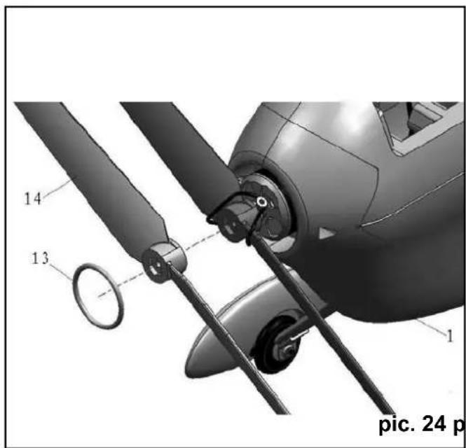
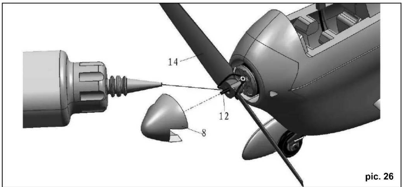
8. Installing the motor and propeller (Figs. 23 - 26):
Slip the speed controller through the motor bulkhead, and permanently fi x the motor in place using the retaining screws 25 (2 x 5 mm). Attach the propeller 14 to the motor using the propeller adapter ring 15. Glue the locating pin 12 in the propeller with a little Zacki, then add the spinner, again using a little Zacki or contact cement.
9. Installing the receiver and fl ight battery (Figs. 27 & 28):
Connect all the servos to the receiver in the sequence stated in your RC system instructions, then push the receiver into the nose compartment as shown in Fig. 27. Install the flight pack in the forward position.
10. Balancing (Figs. 29 & 30):
Push the battery hatch into place, and balance the model on your fingertips: the correct Centre of Gravity position is 95 - 105 mm, measured from the wing leading edge at the root.
11. Recommended control surface travels
for the classic aerobatic schedule:
| Rudder: 80 mm right / left, 50% EXPO | |
| Elevator: 40 mm up, 40 mm down, 40% EXPO | |
| Ailerons: 35 mm up, 35 mm down, 40% EXPO | |
| Mixer (linear): 2% aileron to rudder, opposite travel →i.e.: ailerons defl ect left by 2% at full right-rudder |
For 3D aerobatics:
Rudder: 110 mm right / left, 60% EXPO
Elevator: As much as possible up / down, 60% EXPO
Ailerons: 95 mm up / 75 mm down, 60% EXPO
Mixer (linear): 5% aileron to rudder opposite travel →i.e.: ailerons defl ect left by 5%
at full right-rudder
Part No. Qty Description Material Dimensions
1 1 Fuselage Elapor Ready made
2 1 Wing Elapor Ready made
3 1 Tailplane Elapor Ready made
4 1 Rudder Elapor Ready made
5,6 2 Brace support
7 1 Battery hatch
8 3 Spinner
9 1 Fin in-fill piece
10 1 Left-hand undercarriage leg
11 1 Right-hand undercarriage leg
12 2 Spinner centring pin
13 2 O-ring for attaching propeller
14 1 Propeller, GWS EP
15 2 Propeller adapter ring
15 2 Tailplane brace
16 2 Front wing brace
17 2 Rear wing brace
18 2 Aileron pushrod
19 1 Elevator pushrod
20 1 Rudder pushrod
21 1 Rudder pull-cable
22 4 Screw
23 4 Washer
24 1 L.H. aileron horn
24 3 Pushrod clevis
25 4 Motor mounting screw
26 1 STUNTMASTER building instructions
27 1 Model complaint processing form
Elapor Ready made
Elapor Ready made
Elapor 40 mm ∅
Elapor Ready made
Elapor Ready made
Elapor Ready made
CFRP 2.5 x 13
Rubber 17 mm ∅
Plastic 9 x 5"
Aluminium 10 mm ∅
CFRP / plastic approx. 1.5 x 130 mm
CFRP / plastic approx. 1.3 x 300 mm
CFRP / plastic approx. 1.3 x 305 mm
CFRP / plastic approx. 1.3 x 130 mm
CFRP / plastic approx. 1.3 x 510 mm
CFRP / plastic approx. 1 3 x 620 mm
Kevlar approx. 3.3 m long
Metal 1.4 x 6 mm
Metal 5 mm ∅
Plastic Ready made
Plastic Ready made
Metal 2 x 5 mm
Paper Din A 4
Paper Din A 5
natural_image
3D mechanical assembly diagram showing a tool interacting with a component, labeled with number 1 and 9 (no text or symbols beyond labels)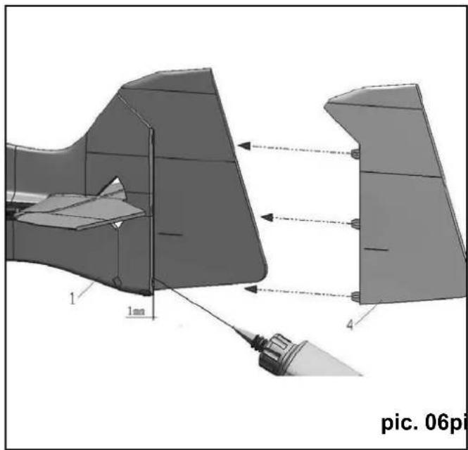
natural_image
Technical diagram of a jet engine component with labeled parts and directional arrows (no readable text or symbols)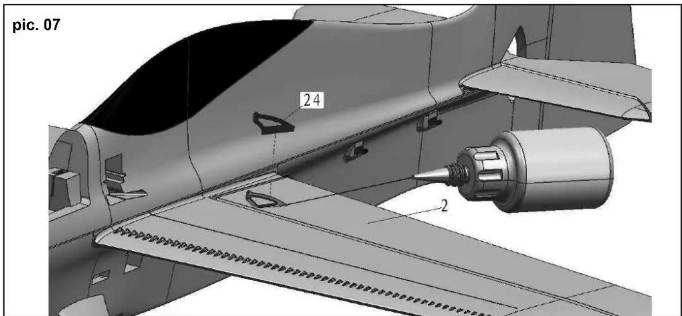
text_image
pic. 07 24 2Seite 22
text_image
pic. 04 pic. 08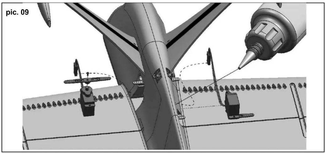
natural_image
3D technical illustration of an aircraft fuselage with a tool and assembly, showing structural components and no visible text or symbols.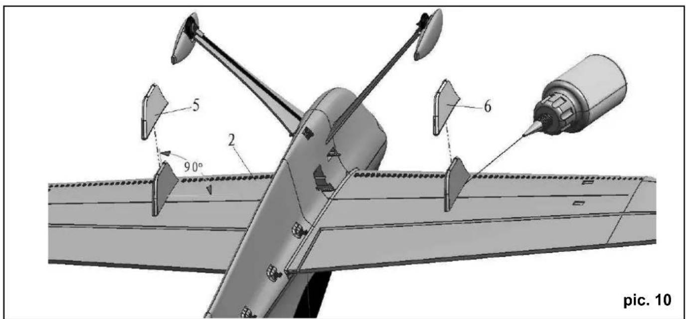
text_image
5 2 90° 6 pic. 10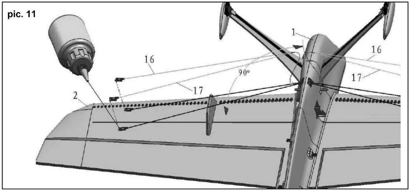
text_image
pic. 11 1 2 16 17 90° 1 16 17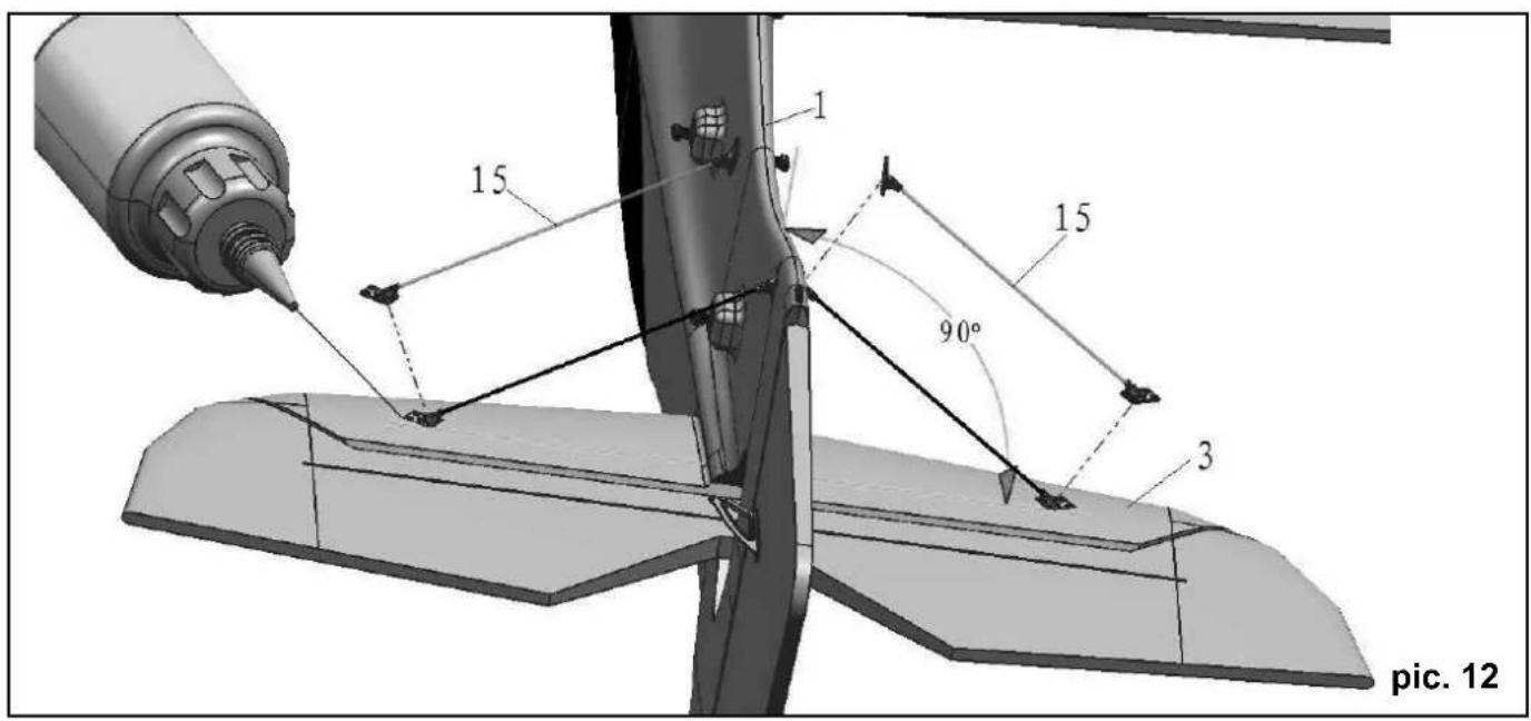
text_image
15 1 15 90° 3 pic. 12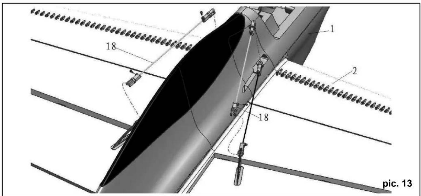
text_image
1 2 18 18 pic. 13
natural_image
3D CAD model of a mechanical assembly with a black cylindrical component and curved pipe (no text or symbols visible)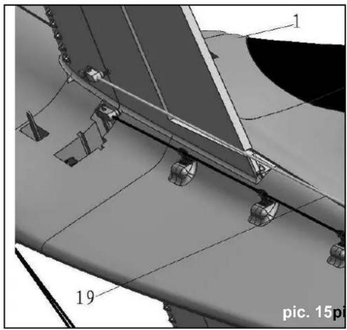
natural_image
Technical diagram of aircraft fuselage components with numbered parts (1 and 19), no readable text or symbols beyond labels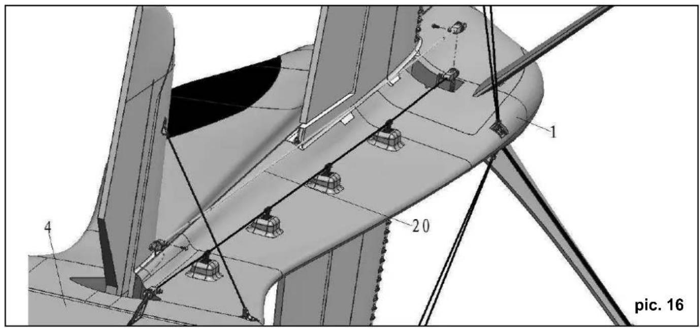
text_image
1 20 4 pic. 16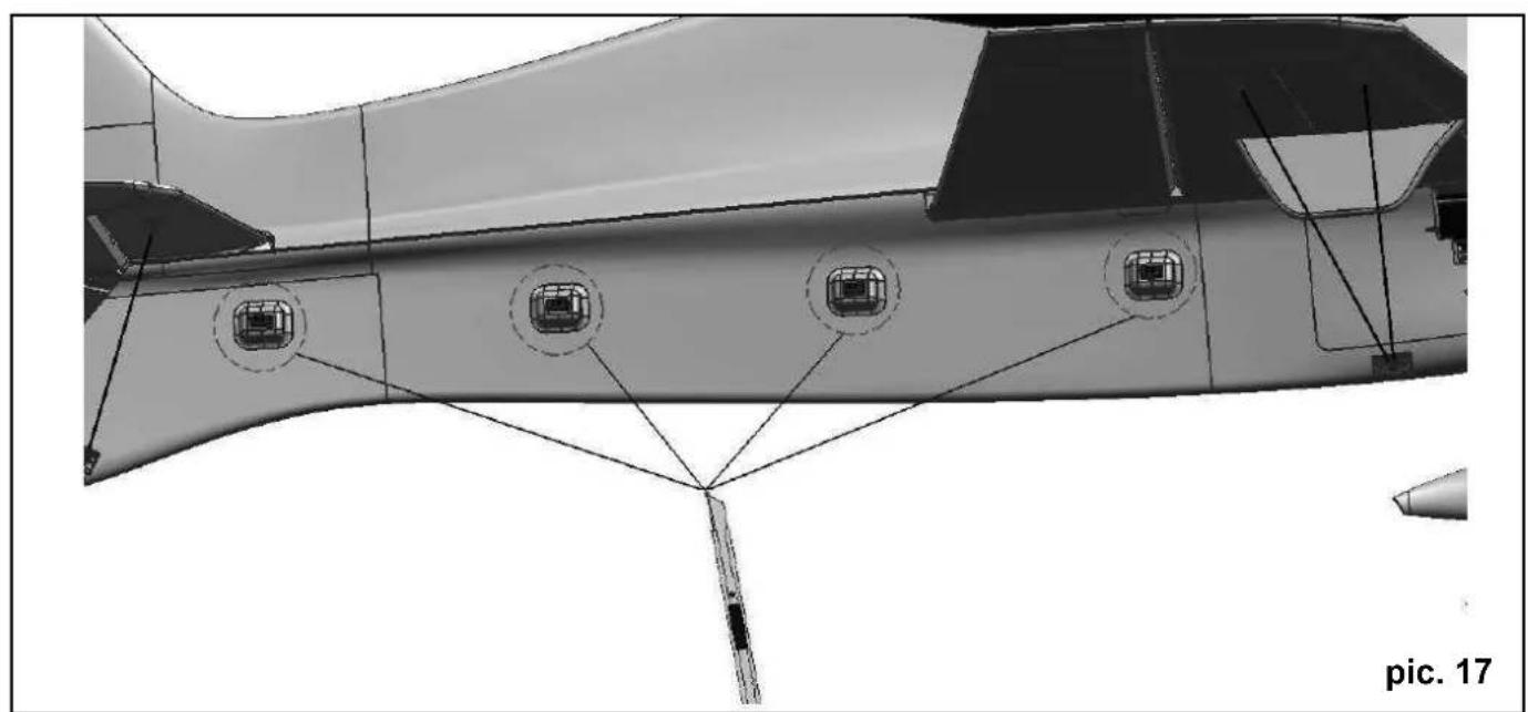
natural_image
Technical diagram of a aircraft fuselage with labeled components and structural details (no readable text or symbols)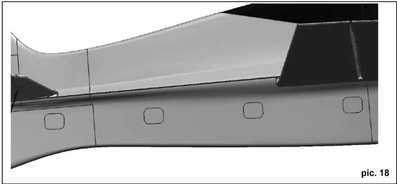
natural_image
Technical illustration of an aircraft fuselage with visible structural details and mounting holes (no text or symbols)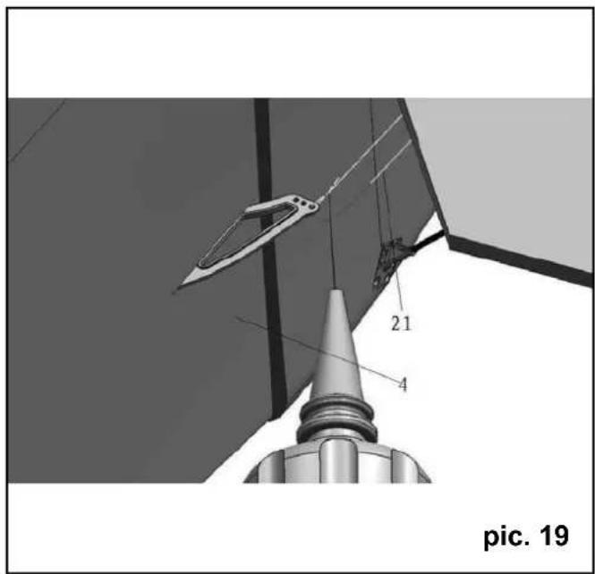
text_image
21 4 pic. 19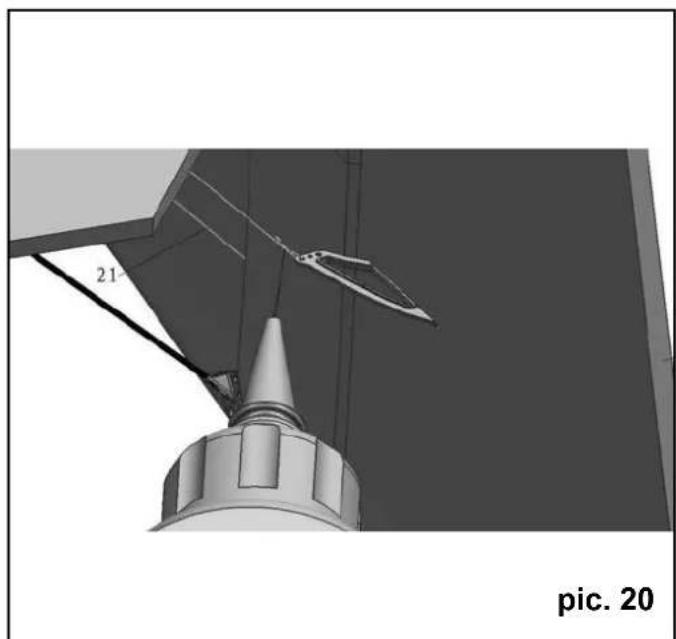
natural_image
3D rendering of a mechanical structure with a conical base and angular component, labeled 'pic. 20' (no readable text or symbols beyond label)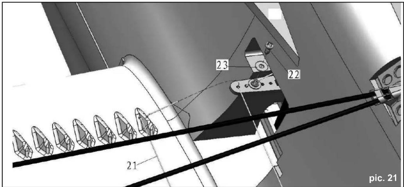
text_image
23 22 21 pic. 21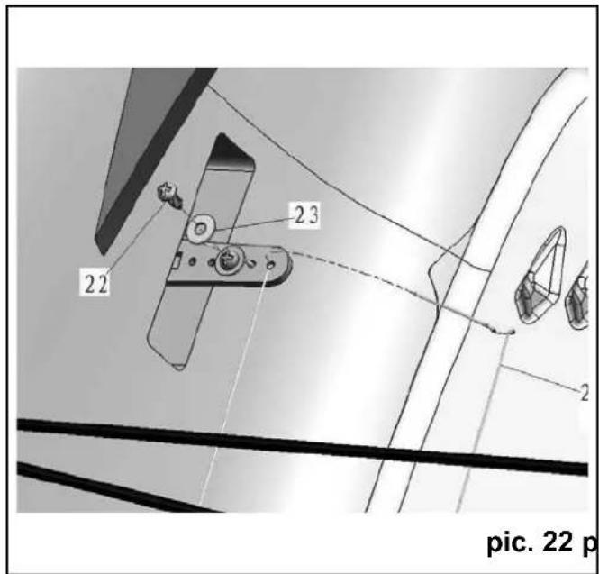
text_image
22 23 2 pic. 22 p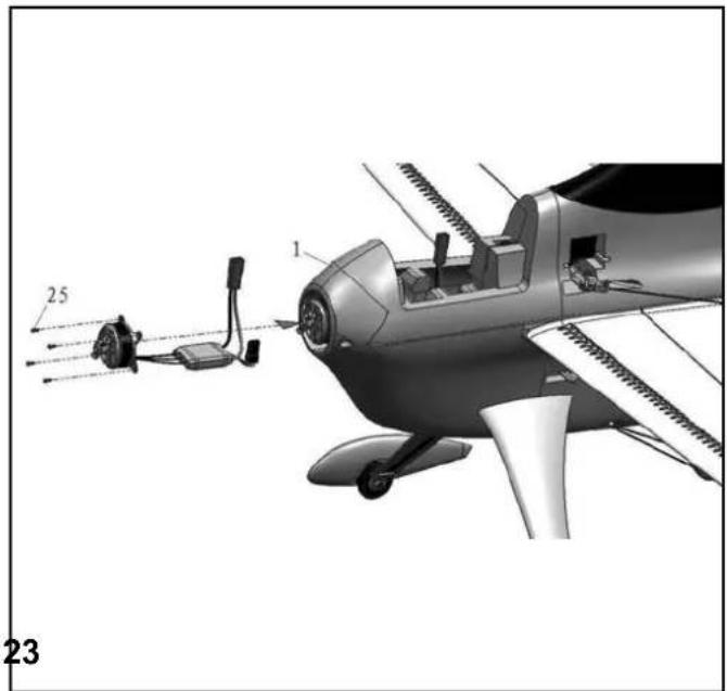
natural_image
Technical illustration of a small aircraft with labeled parts and wiring, showing internal components and no readable text or symbols.pic. 22 pic. 23
text_image
14 13 1 pic. 24 p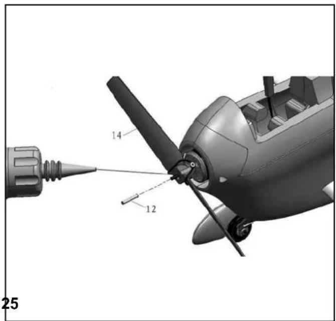
text_image
14 12 25pic. 24 pic. 25
text_image
14 12 8 pic. 26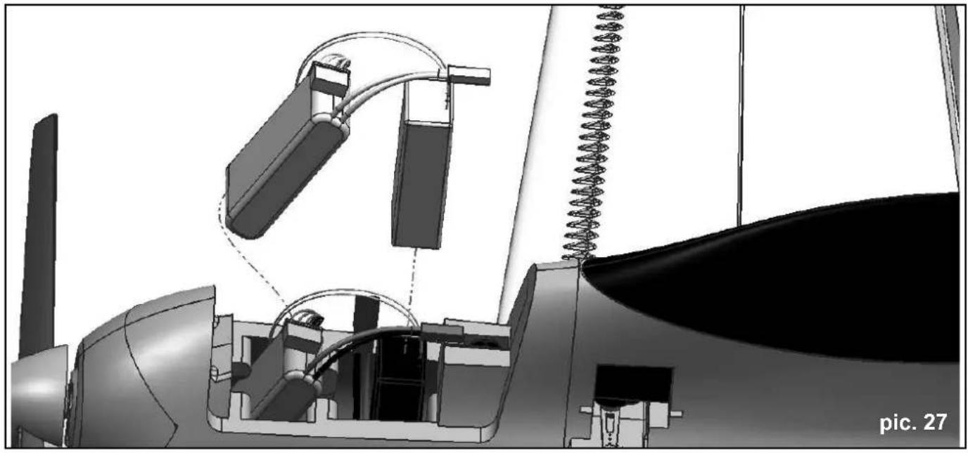
natural_image
3D mechanical assembly diagram showing internal components and wiring connections (no text or symbols)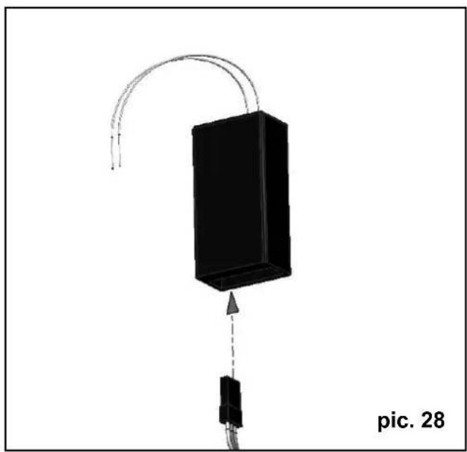
natural_image
3D diagram of a device with a black rectangular block and curved arrows, labeled 'pic. 28' (no text or symbols on the object itself)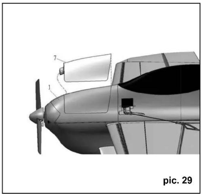
natural_image
Technical illustration of a propeller airplane with labeled parts (1, 7), no visible text or symbols beyond labels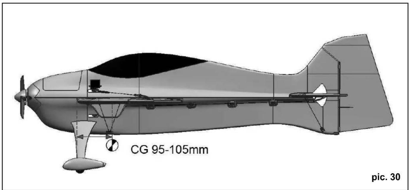
text_image
CG 95-105mm pic. 30Direction:
natural_image
Black-and-white illustration of a car crossing over snow-covered ground (no text or symbols)
text_image
Prohibition sign with crossed-out lines and symbolic imagery, likely for transportation or road safety
natural_image
Symbolic illustration of transmission towers crossed out, representing power lines or transmission (no text present)
natural_image
Weather warning symbol with lightning and rain (no text or numbers)Rischi residui
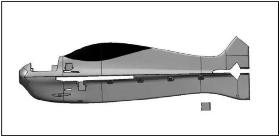
Fuselage (without electrics, battery cap)
natural_image
Cross-sectional diagram of a submarine or aircraft showing internal components and structural details (no text or labels)22 4377
22 4380
# 22 4377
Akkudeckel /
Battery cap
# 22 4380
Höhenleitwerk
Elevator
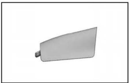
natural_image
Simple 3D-rendered object resembling a curved blade or wedge with a protruding rod (no text or symbols)22 4381
22 4378
natural_image
3D rendered model of a symmetrical mechanical component with no visible text or symbols# 22 4381
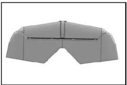
Hauptfahrwerk /
Main landing gear
# 22 4378
natural_image
Two identical conical glass stand designs with vertical and horizontal shafts, no text or symbols visible.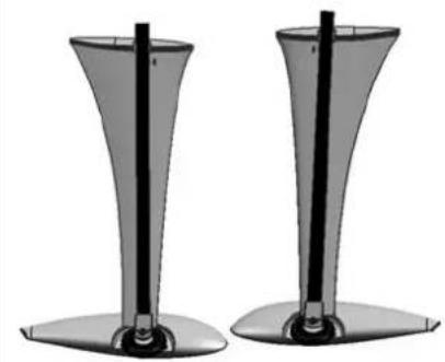
natural_image
Two identical conical glass stand holders with vertical shafts, no text or symbols visible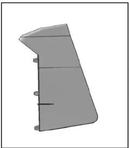
natural_image
3D rendered mechanical part with a tapered blade and mounting holes (no text or symbols)# 22 4379
natural_image
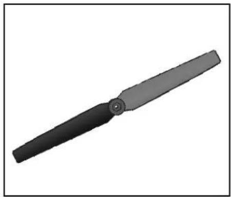
Technical line drawing of a boat hull with visible hull, hull, and support structure (no text or symbols)73 2505
22 4382
73 2505
Propeller GWS EP-9x5"
22 4382
Spinner
natural_image
3D rendered image of a black-handled tool or plunger with a cylindrical handle (no text or symbols)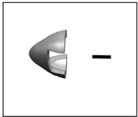
natural_image
3D rendered mechanical component with a curved blade and a rectangular end, shown in two different angles (no text or symbols)22 4386 # 22 4385
22 4386
natural_image
Collection of mechanical components and fasteners including brackets, gears, and a central knob (no text or symbols visible)22 4383
natural_image
Pure electrical circuit lines without any symbols22 4384
natural_image
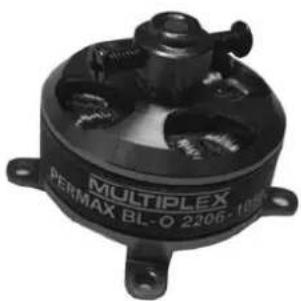
Pure diagram of four horizontal lines with arrowheads, no text or symbols present33 3119
Motor
PERMAX BL-O 2206-1050
natural_image
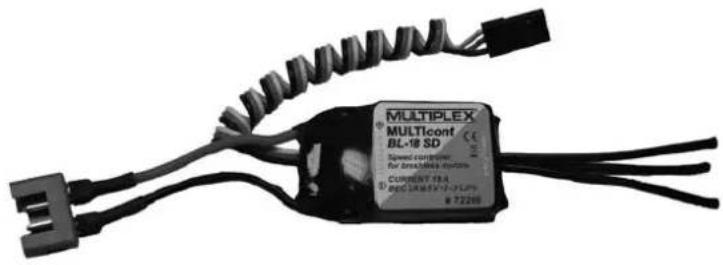
Exterior view of a black multiflexing device with no visible text or symbols on the body itself.7 2266
Regler / ESC
MULTIcont BL-18 SD
text_image
MULTIPLEX MULTIcont BL-18 SD Speed control for broadband system CURRENCY TRA #72200 #722006 5113
Servo MS-12016
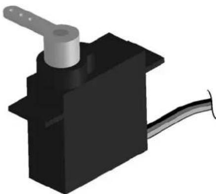
natural_image
3D rendering of a black mechanical component with a metallic lever and cable (no text or symbols)MULTIPLEX®