RTF SHARK - Remote control toy MULTIPLEX - Free user manual and instructions
Find the device manual for free RTF SHARK MULTIPLEX in PDF.

| Product type | Radio-controlled model airplane (RTF) |
| Brand | MULTIPLEX |
| Model | RTF SHARK |
| Wingspan | 1070 mm |
| Overall length | 870 mm |
| Flying weight | 500 g |
| Wing area | 19.5 dm² |
| Wing loading | 26 g/dm² |
| Control channels | 3 to 5 (rudder, elevator, motor, optional ailerons) |
| Flight duration | Approx. 12 minutes (with Li-BATT FX 3/1-950 battery) |
| Power supply | Propulsion battery Li-BATT FX 3/1-950 (3S 950 mAh); SMART-SX transmitter with 3 AA batteries; MULTIcharger L-703 EQU charger |
| Motorization | Brushless motor PERMAX BL-O 2816-1450, MULTIcont BL-12 SD speed controller, propeller 5.5x4.5" |
| Servos | 2 MS-12015 servos (for rudder and elevator) |
| Material | ELAPOR® (resistant foam) |
| Assembly | Pre-assembled model (RR, RR+, RTF versions): snap-on wings and stabilizer |
| Minimum age | 14 years (under adult supervision); keep away from children under 3 years |
| Usage | Outdoor flight in calm, windless weather, in an open area |
| Safety | Range test mandatory before each flight; liability insurance recommended; do not fly over people or animals |
| Maintenance | Clean with a dry cloth; store batteries in a safe place; check propellers and fasteners |
| Optional accessories | Aileron set (#65165), landing gear (#224327), floats (#224328), protection skids (#224329), MULTilight lighting set (#73020) |
| Manual | 48 pages, available in several languages (FR, DE, EN, ES, IT, etc.) |
Frequently Asked Questions - RTF SHARK MULTIPLEX
User questions about RTF SHARK MULTIPLEX
0 question about this device. Answer the ones you know or ask your own.
Ask a new question about this device
Download the instructions for your Remote control toy in PDF format for free! Find your manual RTF SHARK - MULTIPLEX and take your electronic device back in hand. On this page are published all the documents necessary for the use of your device. RTF SHARK by MULTIPLEX.
USER MANUAL RTF SHARK MULTIPLEX
Restrisiken
7.1 Querruder-Upgrade (pic. 16&17):
natural_image
Side profile illustration of a futuristic aircraft with visible tail and fuselage, labeled B (no text or symbols on the aircraft itself)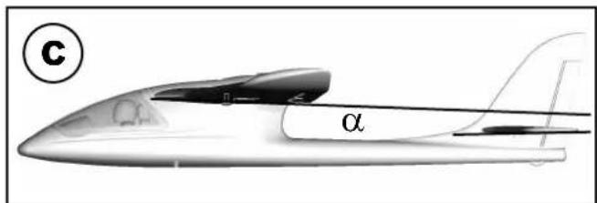

natural_image
Diagram showing a mechanical assembly with a pin, two circular components, and a propeller-like shape with rotational arrows (no text or symbols)This model is NOT A TOY in the usual sense of the term.
By operating the model the owner affi rms that he is aware of the content of the operating instructions, especially those sections which concern safety, maintenance, operating restrictions and faults, and is capable of fulfilling these requirements.
This model must not be operated by any child under fourteen years of age. If a person below this age operates the model under the supervision of a competent adult who is acting as the child's guardian within the legal sense of the term, this individual is responsible for the implementation of the information in the OPERATING INSTRUCTIONS.
THE MODEL AND ASSOCIATED ACCESSORIES MUST BE KEPT OUT OF THE REACH OF CHILDREN UNDER THREE YEARS OF AGE! MODELS CONTAIN SMALL DETACHABLE PARTS WHICH MAY BE SWALLOWED BY CHILDREN UNDER THREE YEARS. CHOKING HAZARD!
All the warnings in the OPERATING INSTRUCTIONS must be observed whenever the model is operated. Multiplex Modellsport GmbH & Co. KG accepts no liability for loss or damage or any kind which occurs as a result of incorrect operation or misuse of this product, including the accessories required for its operation. This includes direct, indirect, deliberate and accidental loss and damage, and all forms of consequent damage.
Every safety note in these instructions must always be observed, as all the information contributes to the safe operation of your model. Use your model thoughtfully and cautiously, and it will give you and your spectators many hours of pleasure without constituting a hazard. Failure to operate your model in a responsible manner may result in significant property damage and severe personal injury. You alone bear the responsibility for the implementation of the operating instructions and the safety notes.
Approved usage
The model is approved exclusively for use within the modelling hobby. It is prohibited to use the model for any other purpose than that stated. The operator of the model, and not the manufacturer, is responsible for damage or injury of any kind resulting from non-approved use.
The model may only be operated in conjunction with those accessories which we expressly recommend. The recommended components have undergone thorough testing, are an accurate match to the model, and ensure that it functions safely. If you use other components, or modify the model, you operate it at your own risk, and any claim under guarantee is invalidated.
To minimise the risk when operating the model, please observe the following points:
- The model is guided using a radio control system. No radio control system is immune to radio interference, and such interference may result in loss of control of the model for a period of time. To avoid collisions, you must therefore ensure at all times that there is a wide margin of safety in all directions when operating your model. At the slightest sign of radio interference you must cease operating your model!
- Never operate your model until you have successfully completed a thorough check of the working systems, and carried out a range-check as stipulated in the instructions supplied with your transmitter.
- The model may only be flown in conditions of good visibility. You can avoid being temporarily blinded by not fl ying towards the sun, or in other diff cult light conditions.
- A model must never be operated by a person who is under the influence of alcohol, drugs or medication which have an adverse effect on visual acuity and reaction time.
- Only fly your model in conditions of wind and weather in which you are able to maintain full control of the model. Even when the wind is light, bear in mind that turbulence can form at and around objects which may have an effect on the model.
- Never fly in any location where you may endanger yourself of others, e.g. close to residential areas, overhead cables, open roads and railway lines.
- Never fly towards people or animals. You may think that flying low over other people's heads is proof of your piloting skill, but all it does is place others at unnecessary risk. It is in all our interests that you let other pilots
know that this is what you think. Always fly in such a way that you do not endanger yourself or others. Bear in mind that even the best RC system in the world is subject to outside interference. No matter how many years of accident-free flying you have under your belt, you have no idea what will happen in the next minute.

natural_image
Black-and-white photo of a car on a road with diagonal cross lines (no visible text or symbols)
natural_image
Two transmission towers crossed out by a diagonal line, symbolizing power lines or transmission (no text or symbols present)
natural_image
Weather warning symbol with lightning and cloud graphic (no text)Residual risks
Even if the model is operated in the correct manner, and you observe all safety aspects, there is always a certain residual risk.
For this reason it is mandatory to take out third-party liability insurance. If you join a club or flying association, insurance is usually available or included in the annual fee. Make sure that your insurance cover is adequate (i.e. that it covers powered model aircraft). Always keep your models and your radio control equipment in perfect order.
The following hazards may occur owing to the model's construction and type:
- Injury caused by the propeller: you must keep well clear of the area around the propeller from the moment that the battery is connected. Please bear in mind that objects in front of the propeller may be sucked into it, and objects behind the propeller may be blown away by it. The model may start moving when the propeller starts to turn. You must therefore position the model in such a way that it cannot move towards other persons if the motor should unexpectedly start running. When you are carrying out adjustment work involving the running motor, you must ensure that the model is always held securely by an assistant.
- Crash caused by pilot error: this can happen even to the best of pilots, so it is essential to fly exclusively in a safe environment: an approved model flying site and suitable insurance are basic essentials.
- Crash caused by technical failure or unnoticed damage in transit or in the workshop. A thorough check of the model before every flight is essential. However, you should also take into account at all times that material failures can and do occur. Never fly in a location where your model may damage or injure others.
- Keep within the stated operating limits. Excessively violent flying will weaken the airframe, and may result in sudden material failure, or may cause the model to crash during a subsequent flight due to “creeping” consequent damage.
- Fire hazard caused by electronic failure or malfunction. Store batteries safely, and always observe safety notes which apply to the airborne electronic components, the battery and the battery charger. Protect all electronic equipment from damp. Ensure that the speed controller and battery are adequately cooled.
The instructions which accompany our products must not be reproduced and / or published, in full or in part, in print or any electronic medium, without the express written approval of Multiplex Modellsport GmbH & Co. KG.
Technical information SHARK
Wingspan: 1070 mm
Overall length: 870 mm
All-up weight: 500 g
Total surface area: 19,5 dm²
Wing loading: 26 g/dm²
Channels:
3-5
RC Functions:
rudder, elevator, motor, optional aileron
Flight time:
ca. 12 min (3S \~950Ah)
MULTIPLEX model kits are subject to constant quality checks throughout the production process, and we sincerely hope that you are completely satisfied with the contents of your kit. However, we would ask you to check all the parts before you start construction, as we cannot exchange components which you have already worked on. If you find any part is not acceptable for any reason, we will readily correct or exchange it. Just send the component to our Model Department. Please be sure to include the purchase receipt and a brief description of the fault.
We are constantly working on improving our models, and for this reason we must reserve the right to change the kit contents in terms of shape or dimensions of parts, technology, materials and fittings, without prior notification. Please understand that we cannot entertain claims against us if the kit contents do not agree in every respect with the instructions and the illustrations.
Caution!
Radio-controlled models, and especially model aircraft, are by no means playthings. Building and operating them safely requires a certain level of technical competence and manual skill, together with discipline and a responsible attitude at the fl ying fi eld. Errors and carelessness in building and fl ying the model can result in serious personal injury and damage to property. Since we, as manufacturers, have no control over the construction, maintenance and operation of our products, we are obliged to take this opportunity to point out these hazards and to emphasise your personal responsibility.
This model is not made of styrofoam ^™ , and it is not possible to glue the material using white glue or epoxy. Please be sure to use cyano-acrylate glue exclusively, preferably in conjunction with cyano activator (kicker). We recommend medium-viscosity cyano. This is the procedure: spray cyano activator on one face of the Elapor®; allow it to air-dry, then apply cyano adhesive to the other face. Join the parts, immediately position them accurately, and wait a few seconds for the glue to harden.
Recommended equipment:
| Item number Pieces Description: | RR RR+ | RTF Mode 1/3 | RTF Mode 2/4 | |||
| # 55839 1 Receiver RX-5 M-LINK ID 9 ● | ||||||
| # 157321 1 Battery Li-BATT FX 3/1-950 (M6) ● | ||||||
| # 15300/ 15301 | 1 | Transmitter SMART-SX | ● | ● | ||
| # 82523 1 MULTIcharger L-703 EQU ● | ● | |||||
Optional equipment:
| Item number Pieces Description: RR RR+ | RTF Mode 1/3 | RTF Mode 2/4 | ||||
| # 852727 | 1 | Zacki ELAPOR 20g VE1 | ● | ● | ● | ● |
| # 65165 | 1 | Aileron upgrade set | ● | ● | ● | ● |
| # 224327 | 1 | SHARK undercarriage set | ● | ● | ● | ● |
| # 224328 | 1 | SHARK floats set | ● | ● | ● | ● |
| # 224329 | 1 | SHARK landing skid | ● | ● | ● | ● |
| # 73020 | 1 | MULTIlight, 5 LEDs | ● | ● | ● | ● |
| # 92545 1 | Combo MULTIcharger LN-3008 EQU | ● | ● | ● | ● | |
| # 92516 | 1 | Charge lead w. high current plug (M6) | ● | ● | ● | ● |
Please take care when handling cyano-acrylate adhesives. These materials harden in seconds, so don't get them on your fingers or other parts of the body. We strongly recommend the use of goggles to protect your eyes. Keep the adhesive out of the reach of children.
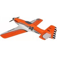
SHARK - the FUN fl yer!
As inventors of the world-famous EasyStar, we decided that our next aeroplane would be a modern, user-friendly design which would guarantee a one hundred percent FUN factor. We wanted to create a model which could grow as the owner's skills developed, and would never become boring.
The outcome is something very special - the MULTIPLEX SHARK!
The SHARK looks terrific in its unusual colour scheme, and it lies fantastically well. In its standard form the model is controlled using rudder and elevator, but it is prepared for the aileron option. With the recommend Li-BATT FX 3/1-950 fl light battery a minimum flying time of 10 min is possible!
It takes just a few moments to fit an undercarriage the aeroplane, and with a further "click" it is transformed into a float-plane which provides loads of fun - on snow as well as water. We think every MULTIPLEX SHARK owner should have this optional accessory. And for the aesthetically demanding modeller we can supply a stylish protective landing skid.
When all the fl ying fun's over, the SHARK can very easily be dismantled and packed back into the original carton. Highly practical!
- Benign fl ying qualities, ideal for the beginner; very robust construction
- Powerful brushless motor
- Clear canopy with racing-style pilot
- Wide range of optional upgrades (protective landing skid, undercarriage, floats, aileron upgrade, MULTilight)
• Original carton doubles as transport box
Set contents, RR:
ELAPOR® model, 100% factory-assembled, including PERMAX BL-O 2816-1450 electric motor, MULTIcont BL-12 SD speed controller, 5.5 x 4.5" propeller, two MS-12015 servos, painted finish, decals already applied, comprehensive instructions
RR+
As above, plus: RX-5 M-LINK ID 9 receiver and Li-BATT FX 3/1-950 (M6) battery.
RTF:
As above, plus: RX-5 M-LINK ID 9 receiver, Li-BATT FX 3/1-950 (M6) battery, SMART-SX transmitter, 3 AA-size dry cells, MULTIcharger L-703 EQU battery charger.
Please check that all components are present by referring to the Parts List on page 16 (pic 01 & 02).
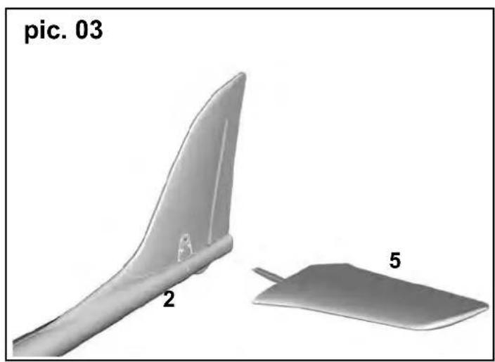
1. Fitting the tailplane (pic. 03-05):
Insert the left-hand tailplane panel 5 into the opening in the rear end of the fuselage / fi n, then push in the right-hand tailplane panel 6 until it snaps into place.
The tailplane can be removed from the fuselage for transport as follows: press the outboard end of the locking lever on the underside of the right-hand tailplane, and withdraw the panels. It is important to check that the tailplane is correctly engaged before every flight.
2. Installing the receiver (pic. 06&07):
→ The following step is only necessary for the RR version.
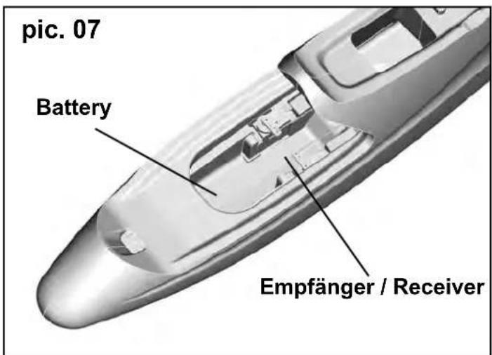
Open the canopy 1 on the fuselage 2, and place it to one side.
Now connect the servos and the speed controller to the receiver. Ensure that the connectors are inserted the right way round, and that they are in the appropriate sockets: the rudder servo is the right-hand one as seen from the tail; the elevator servo is the left-hand one.
The standard channel arrangement (socket sequence) of MULTIPLEX radio control systems (e.g. SMART SX, 15300 / 15301) is as follows:
- L.H. aileron
- Elevator
- Rudder
- Motor (throttle)
- R.H. aileron
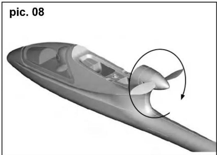
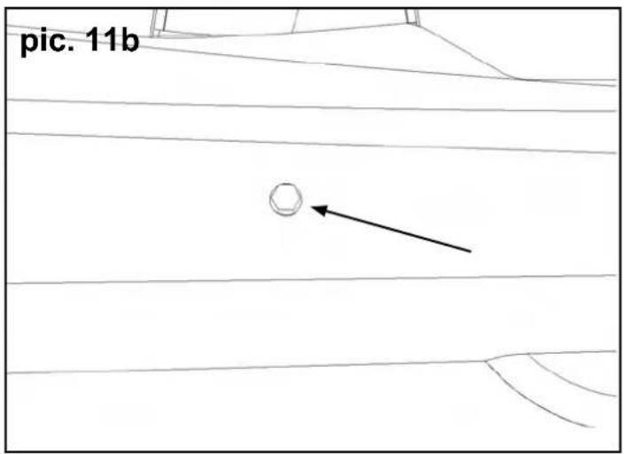
3. Adjusting the servos (pic. 08-11b):
Before you connect the flight battery for the first time, it is important to check that the model's propeller is free to spin, and that the model is securely held. The thrust generated by the propeller should not be under-estimated; it is quite strong enough to suck loose items into the airflow. If you do not have prior experience with powered model aircraft, we recommend that you ask a friend to help you at this stage.
Connect the flight battery, and check the direction of rotation of the servos. If your model is the RR+ / RTF version, the servos are already correctly set up for Mode 1 / 3 or 2 / 4.
The following functions must work as follows if the first flight is to be successful:
- Pull elevator stick back (towards you) --> trailing edge of elevator must deflect up
- Push elevator stick forward (away from you) --> trailing edge of elevator must deflect down
- Move rudder stick right --> rudder must deflect to the right
- Move rudder stick left --> rudder must deflect to the left
- Throttle (motor) stick forward --> Motor speed must rise
- Throttle (motor) stick back --> Motor speed must fall
If any control function works in the wrong direction, you must reverse the corresponding channel to correct it. If you are not sure how to do this, refer to the operating instructions supplied with your radio control system. When the tailplane is in the neutral position, you will be able to see a socket-head screw through the small hole at the rear on the left-hand side: this indicates the neutral position of the all-moving tailplane. If that is not the case, use the allen key 11 (supplied) to correct the position.
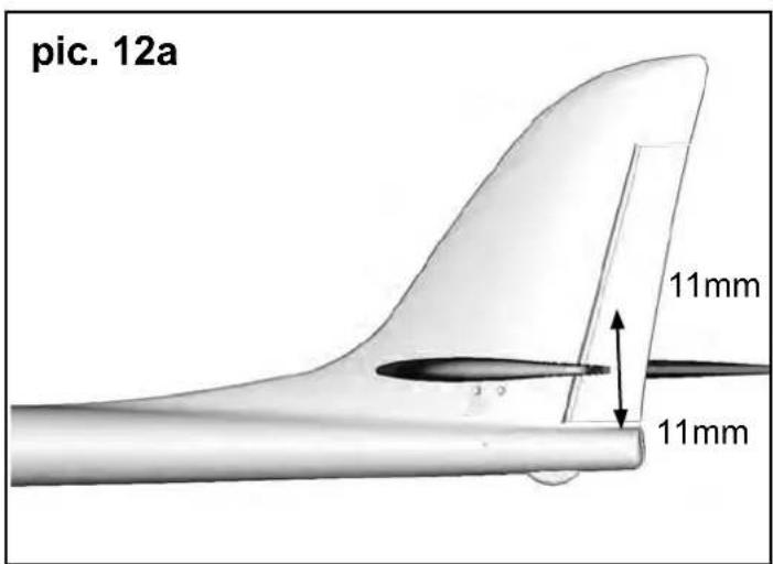
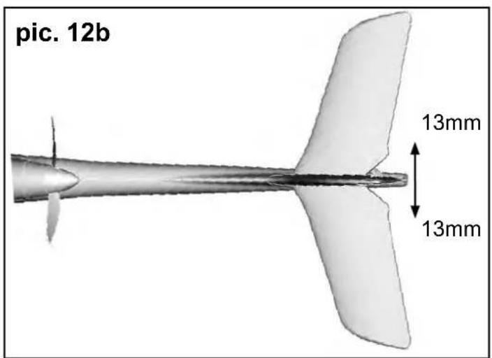
4: Setting the control surface travels (pic. 12 a&b):
It is important to set the control surface travels correctly, as these settings have a crucial influence on the model's overall control response. In all cases the travels are measured at the point of maximum chord (width of control surface.
The control surface travels can be measured using a geometry set-square. Measure the travels at the trailing edge of each panel, starting from the neutral position. The control surface travels should be as follows:
Elevator
up - stick back - approx. + 10 mm down - stick forward - approx. - 10 mm
Rudder
left and right each way - approx. 13 mm
when you have completed this stage, disconnect the flight battery again, and recharge it. Observe the instructions supplied with your battery charger.
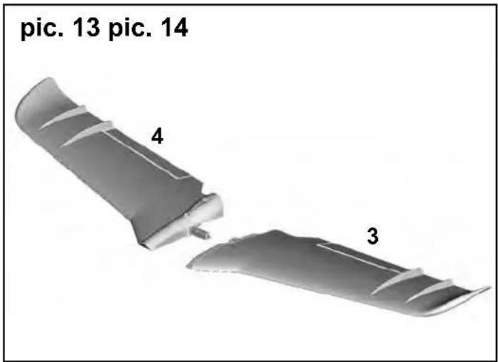
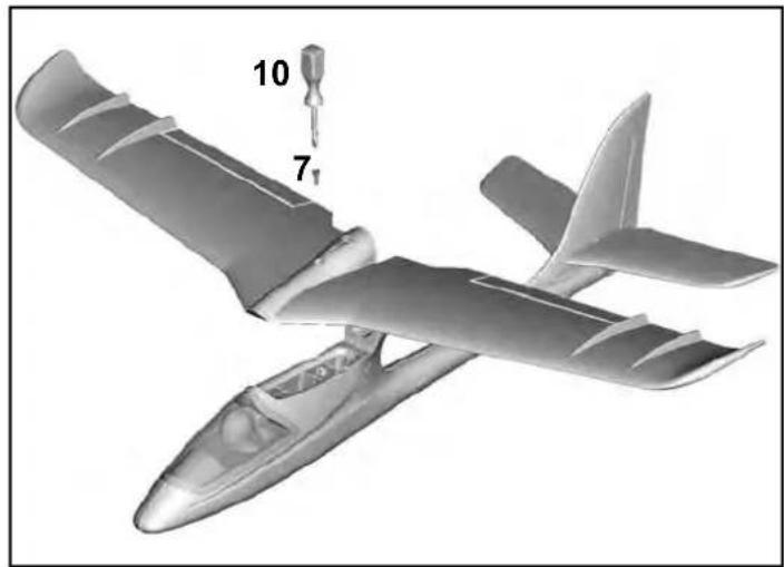
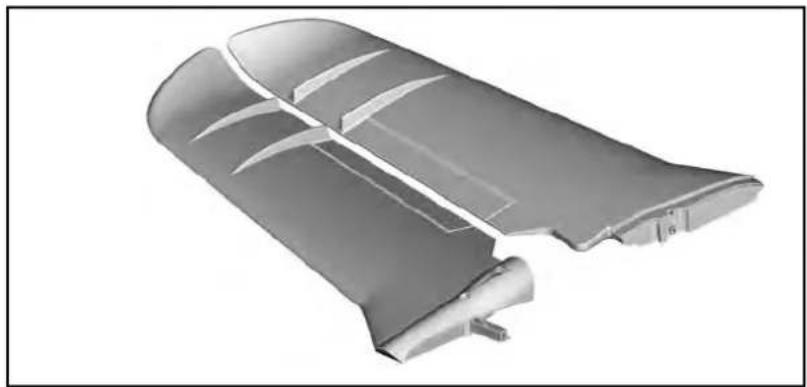
5: Fitting the wings (pic. 14&14):
Take the left-hand wing panel 3 and the right-hand wing panel 4, and fi t them together Attach this assembly to the fuselage using the plastic screw 7 and the screwdriver 10. Don't over-tighten the screw; hand-tight is quite sufficient. Check that the wings are positioned correctly.
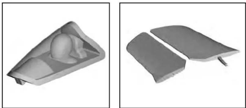
6: Balancing (pic. 15):
To make your SHARK fly safe and stable it must be balanced at the correct point or C.G. (Centre of gravity) - just like every other aircraft. Assemble your model completely, ready to fly. Place the flight battery in the nose of the fuselage (don't connect it at this stage), and place the canopy on the model.
Locate the raised points under each wing root, place both index fingers on those points, and raise the model: the model should now balance level, ideally with the nose inclined slightly down. If so, then the model is balanced
correctly. If you need to adjust the balance point (CG), move the flight battery slightly forward or back. When the position is correct, mark the battery position inside the fuselage with a felt-tip pen.
The Centre of Gravity (CG) of the SHARK is located 27 mm aft of the rear edge of the tubular aluminium spar.
If you can not reach the center of gravity by positioning the RC equipment, a correction is possible with ballast.
7. Upgrading:
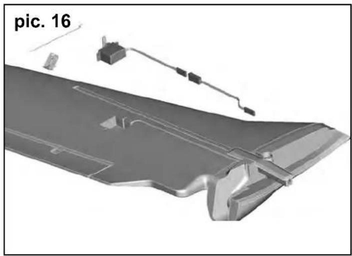
7.1 Aileron upgrade (pic. 16&17):
The model is designed for aileron control. For this you require the optional upgrade set # 6 5165. Using a sharp balsa knife, carefully cut through both ends of the aileron to allow it to deflect up and down; check that the ends do not rub on the wing. Carefully cut through the SHARK sticker on the underside of the wing, and fold it back on itself: under the sticker you will find a recess which fi ts the Nano-S or Ms-12015 servo. Centre the servo from your transmitter, push it into the recess, and glue it to the foam by applying a small drop of Zacki # 85 2727 to each servo lug. Press the cable into the channel, and apply small pieces of adhesive tape over the slot to prevent it working loose. Now cut a slot in the SHARK sticker to allow the servo output arm to move freely in both directions. Glue the horn in the appropriate recess in the aileron. Connect the pre-formed wire pushrod to the servo output arm, and slip the other end through the swivel connector. Check that the servo and the aileron are both at centre (neutral) before tightening the clamping screw using the allen key 11. Repeat the procedure with the other wing.
The ailerons must be set up in such a way that the right-hand aileron defl ects up, and the left-hand aileron defl ects down, when the aileron stick is moved to the right. The travels should be approximately:
Ailerons
up - approx. + 13 mm down - approx. - 9 mm
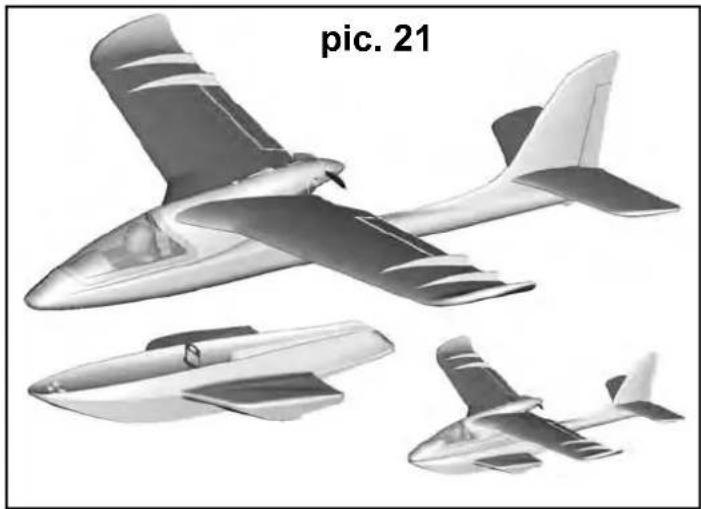
7.2 Undercarriage and fl oats (pic. 18-21):
Simply insert the undercarriage # 22 4327 or the fl oats assembly # 22 4328 in the slot on the underside of the fuselage until it audibly "CLICKS" into place. To remove it again, locate the internal lug between the two control "snakes", and pull it gently towards you: the undercarriage / fl oats assembly can now be withdrawn.
CAUTION: when the floats are fitted, the Centre of Gravity should be at a point 2 mm aft of the rear edge of the tubular aluminium spar.
7.3 Protective landing skid (pic. 22&23):
9. Safety
To protect the model when belly-landing on grass, we recommend fi tting the protective landing skid # 22 4329. This is simply fastened to the underside of the model, and secured with a little adhesive tape or double-sided tape at the rear.
8. Preparing for the first flight
Wait for a day with as little breeze as possible for the first flight. The evening hours often provide the best conditions
Be sure to carry out a range check before the first flight!
The transmitter battery and flight pack must be fully charged according to the instructions.
Set the transmitter to range-check mode, and ask your assistant to walk away from the model, carrying the transmitter.
As he walks away your friend should constantly operate one control function while you watch the model's servos. The servo not being operated should stay motionless up to a range of around 60 m, and the other servo should follow the transmitter stick movements smoothly and immediately. If successful, repeat the check with the motor running. The effective range should not be significantly reduced when the motor is running.
If you are not sure about anything, do not fly the model! If you cannot eliminate the problem send the whole radio control system (including battery, switch harness, servos) to the manufacturer's service department for checking.
The first flight ....
Do not test-glide this model!
The model is designed for hand-launching - always exactly into the wind.
We recommend that you ask an experienced modeller to help you during the first flight.
Allow the model to climb to a safe altitude, then adjust the trims on the transmitter so that the model flies straight ahead without any help from you.
At a safe height switch off the motor and make yourself familiar with the model's control response on the glide. Carry out a dummy landing approach at a good height, so that you will feel confident about the real landing when the flight pack is flat.
Don't attempt tightly banked turns close to the ground at fi rst, and especially not on the landing approach. It is always better to land safely some distance away, and have to walk to collect the model, than to risk damaging it by dragging it close to your feet.
Safety is the First Commandment when fl ying any model aircraft. Third party insurance should be considered a basic essential. If you join a model club suitable cover will usually be available through the organisation. It is your personal responsibility to ensure that your insurance is adequate (i.e. that its cover includes powered model aircraft). Make it your job to keep your models and your radio control system in perfect order at all times. Check the correct charging procedure for the rechargeable batteries used in your RC set. Make use of all sensible safety systems and precautions which are advised for your system. An excellent source of practical accessories is the MULTI-PLEX main catalogue, as our products are designed and manufactured exclusively by practising modellers for other practising modellers.
Always fly with a responsible attitude. You may think that flying low over other people's heads is proof of your piloting skill; others know better. The real expert does not need to prove himself in such childish ways. It is in all our interests that you let other pilots know that this is also what you think. Always fly in such a way that you do not endanger yourself or others. Bear in mind that even the best RC system in the world is subject to outside interference. No matter how many years of accident-free flying you have under your belt, you have no idea what will happen in the next minute. We - the MULTIPLEX team - hope you have many hours of pleasure building and flying your new model.
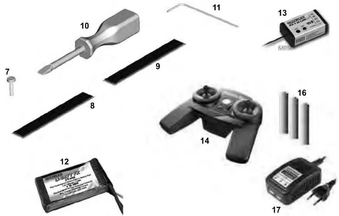
Partlist SHARK
Part No. Quantity Description
| 1 | 1 | Canopy | |
| 2 | 1 | Fuselage and fin | |
| 3 | 1 | Left-hand wing panel | |
| 4 | 1 | Right-hand wing panel | |
| 5 | 1 | Left-hand tailplane panel | |
| 6 | 1 | Right-hand tailplane panel | |
| 7 | 1 | Plastic wing retainer screw | |
| 8 | 2 | Hook-and-loop tape, hook | |
| 9 | 2 | Hook-and-loop tape, loop | |
| 10 | 1 Screwdriver | ||
| 11 | 1 Allen key | ||
| 12 | 1 | Battery, 3S / 950 mAh (only RR+ / RTF) | |
| 13 | 1 | RX5 receiver, ID 9 (only RR+ / RTF) | |
| 14 | 1 Smart SX with manual (only RTF) | ||
| 16 | 1 AA-size dry cell (only RTF) | ||
| 17 | 1 | Plug-type battery charger MULTIcharger L-703 EQU (only RTF) |
Basic information relating to model aircraft
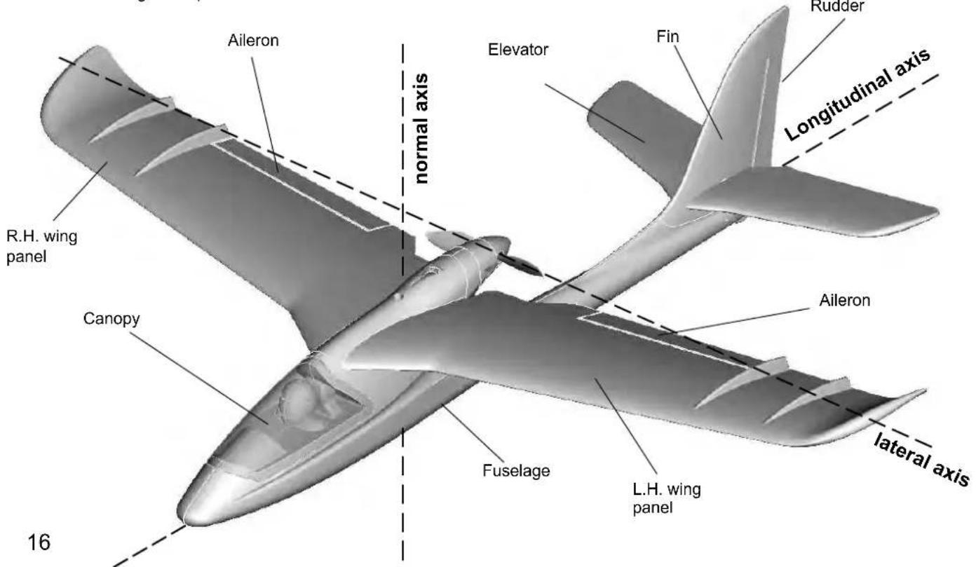
Any aircraft, whether full-size or model, can be controlled around the three primary axes: vertical (yaw), lateral (pitch) and longitudinal (roll).
When you operate the elevator, the model's attitude alters around the lateral axis. If you apply a rudder command, the model swings around the vertical axis. If you move the aileron stick, the model rolls around its longitudinal axis. As our SHARK has considerable wing dihedral, ailerons are not required for roll control. In this case the rudder is used both to turn the model around the vertical axis, and also to roll it (longitudinal axis). External influences such as air turbulence may cause the model to deviate from its intended flight path, and when this happens the pilot must control the model in such a way that it returns to the required direction. The basic method of controlling the model's height (altitude) is to vary motor speed (motor and propeller). The rotational speed of the motor is usually altered by means of a speed controller. Applying up-elevator also causes the model to gain height, but at the same time it loses speed, and this can only be continued until the model reaches its minimum airspeed and stalls. The maximum climb angle varies according to the power available from the motor.
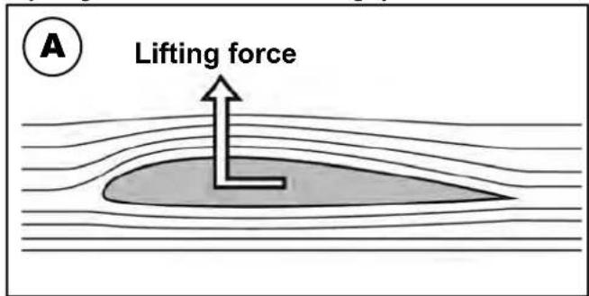
Wing section
The wing features a cambered airfoil section over which the air flows when the model is flying. In a given period of time the air flowing over the top surface of the wing has to cover a greater distance than the air flowing under it. This causes a reduction in pressure on the top surface, which in turn creates a lifting force which keeps the aircraft in the air. Fig. A
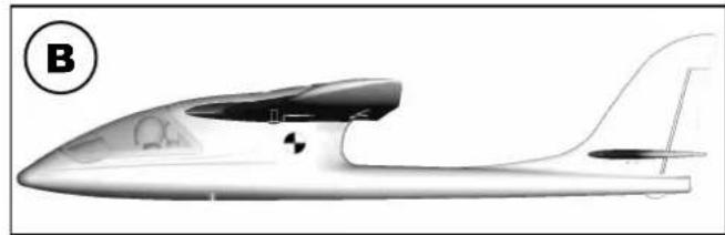
Centre of Gravity (CG)
To achieve stable flying characteristics your model aircraft must balance at a particular point, just like any other aircraft. It is absolutely essential to check and set the correct CG position before flying the model for the first time.
The CG position is stated as a distance which is measured aft from the wing root leading edge, i.e. close to the fuselage. Support the model at this point on two fingertips (or - better - use the MPX CG gauge, # 69 3054); the model should now hang level. Fig. B If the model does not balance level, the installed components (e.g. flight battery) can be re-positioned inside the fuselage. If this is still not sufficient, attach the appropriate quantity of trim ballast (lead or plasticene) to the fuselage nose or tail and secure it carefully. If the model is tail-heavy, fix the ballast at the fuselage nose; if the model is tail-heavy, attach the ballast at the tail end of the fuselage.
The longitudinal dihedral is the difference in degrees between the angle of incidence of the wing and of the tail. Provided that you work carefully and attach the wing and tailplane to the fuselage without gaps, the longitudinal dihedral will be correct automatically. If you are sure that both these settings (CG and longitudinal dihedral) are correct, you can be confident that there will be no major problems when you test-fl y the model. Fig. C
Control surfaces, control surface travels
The model will only fly safely, reliably and accurately if the control surfaces move freely and smoothly, follow the stick movements in the correct "sense", and move to the stated maximum travels. The travels stated in these instructions have been established during the test-flying programme, and we strongly recommend that you keep to them initially. You can always adjust them to meet your personal preferences later on.
Transmitter controls
The transmitter features two main sticks which the pilot moves to control the servos in the model, which in turn operate the control surfaces.
The functions are assigned according to Mode A, although other stick modes are possible.
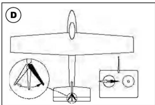
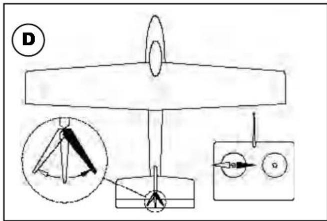
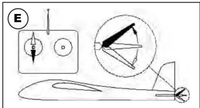
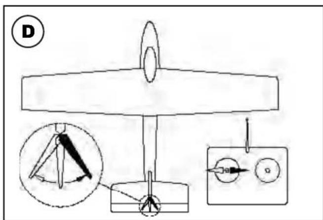
The transmitter controls the control surfaces as follows:
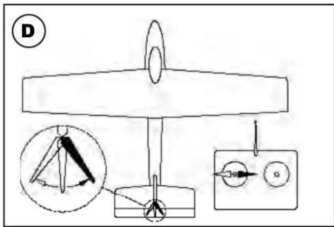
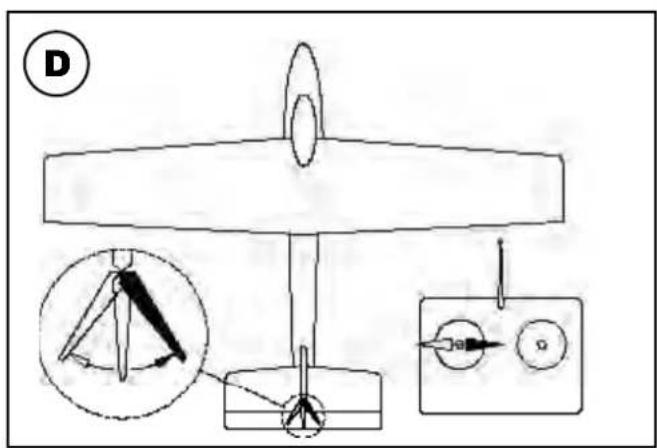
Rudder (left / right) Fig. D
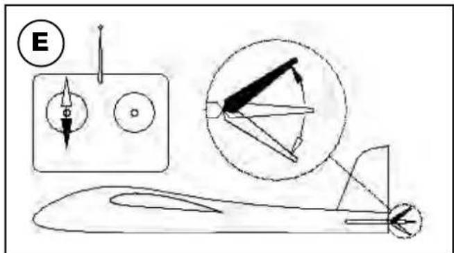
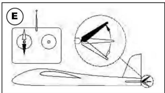
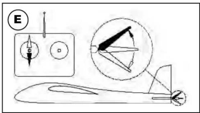
Elevator (up / down) Fig. E
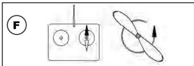
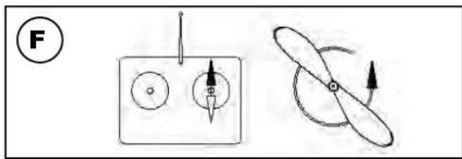
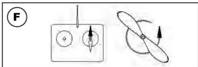
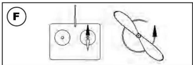
Throttle (motor off / on) Fig. F
Unlike the other controls, the throttle stick must not return to the neutral position automatically. Instead it features a ratchet so that it stays wherever you put it. Please read the instructions supplied with your radio control system for the method of setting up and adjusting the transmitter and receiving system.
natural_image
Side profile illustration of a stylized aircraft or aircraft with visible internal components and tail fin (no text or symbols)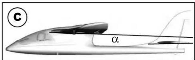
natural_image
Black-and-white illustration of a car crossing a track with diagonal lines (no text or symbols)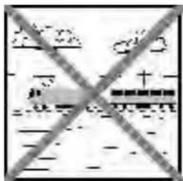

natural_image
Exterior view of high-voltage transmission towers crossed out, no text or symbols visible
natural_image
Weather icon showing lightning under a cloudy sky with no text or symbolsRisques
pic. 02
natural_image
3D model of a propeller or duct component with labeled parts (2 and 5), no text or symbols present.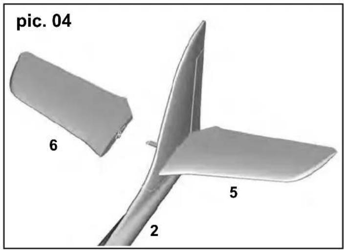
natural_image
3D model of a propeller or fan-like structure with labeled parts (2, 5, 6) and no visible text or symbols beyond labels.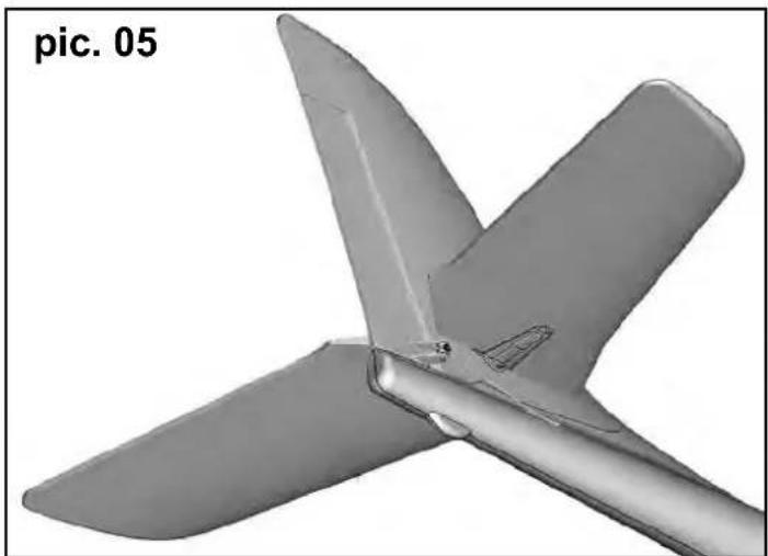
natural_image
3D rendered model of a propeller or fan blade assembly (no text or symbols visible)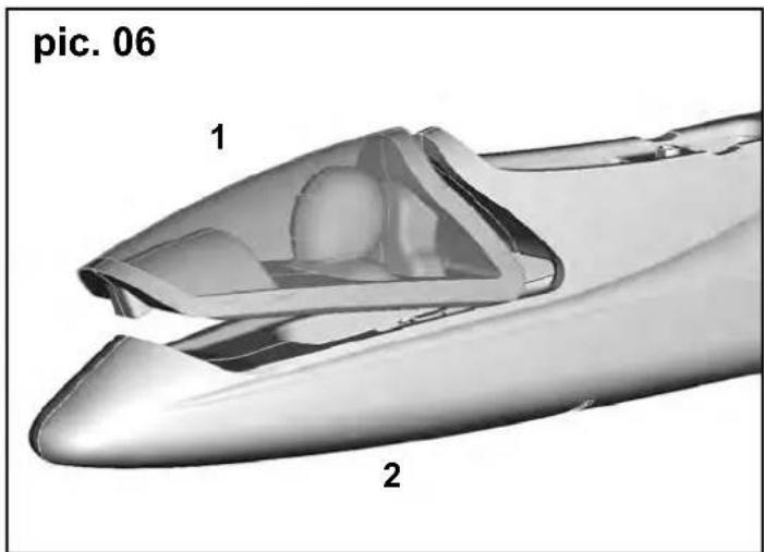
natural_image
3D rendered model of a boat hull with propeller and rotor, showing rotational motion (no text or symbols)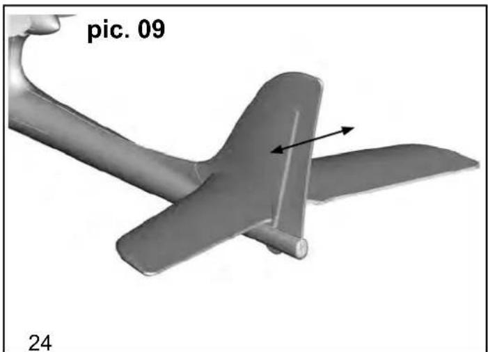
natural_image
3D model of an aircraft with two propellers and a labeled section 'pic. 09' (no other text or symbols)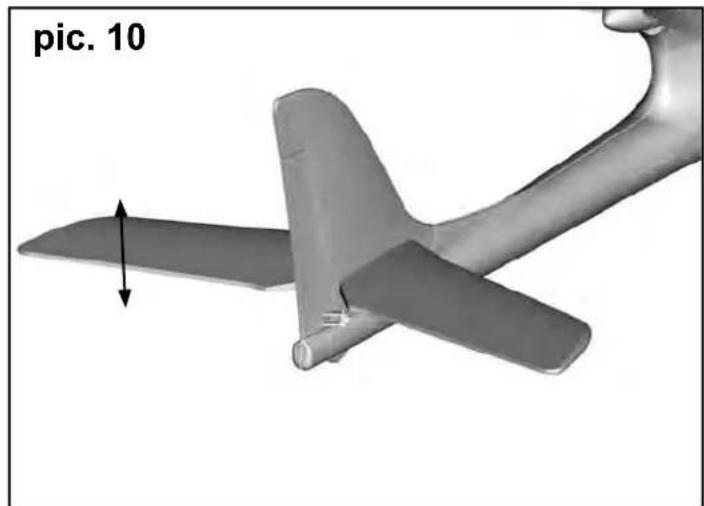
natural_image
3D model of an aircraft with a propeller and arrow indicating motion direction (no text or symbols on the model itself)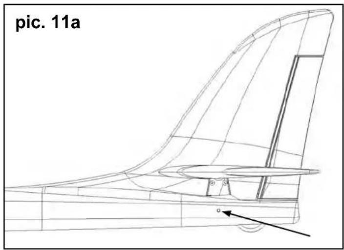
natural_image
3D model of an airplane with labeled parts (10 and 7), no readable text or symbols beyond labels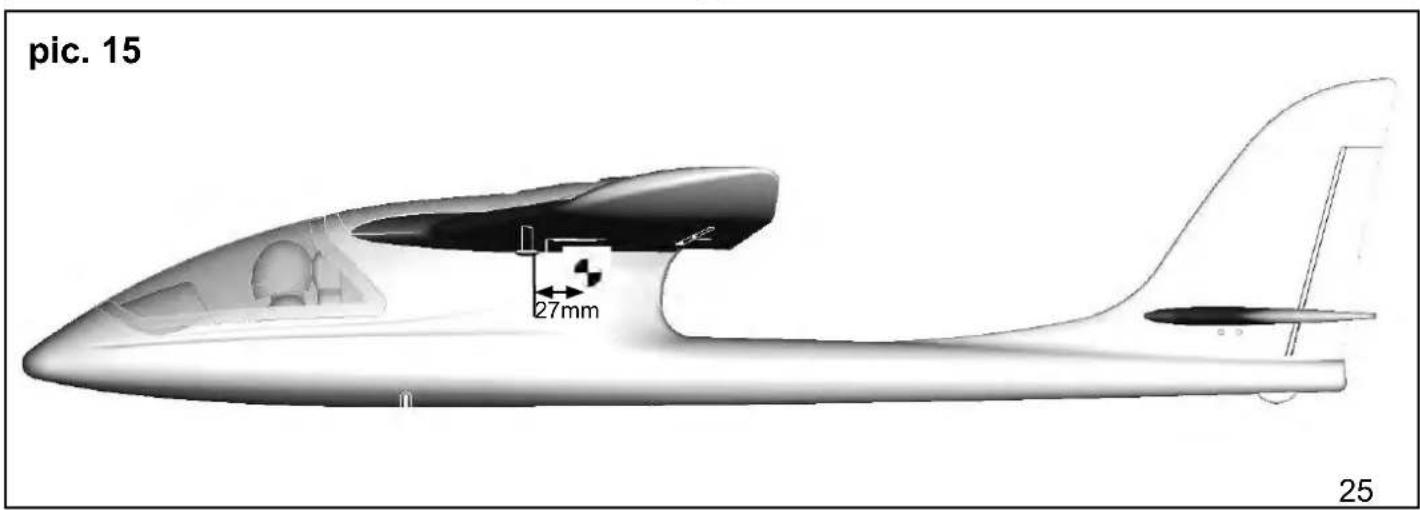
natural_image
3D CAD model of a mechanical component with attached wires and components, labeled 'pic. 16' (no readable text or symbols beyond label)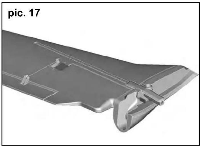
natural_image
3D rendered metallic component with cutouts and mounting holes, labeled 'pic. 17' (no other text or symbols)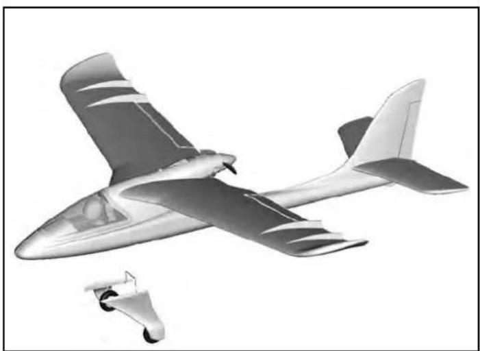
natural_image
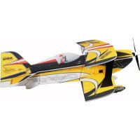
Illustration of a propeller airplane in flight with visible aerodynamic design (no text or symbols)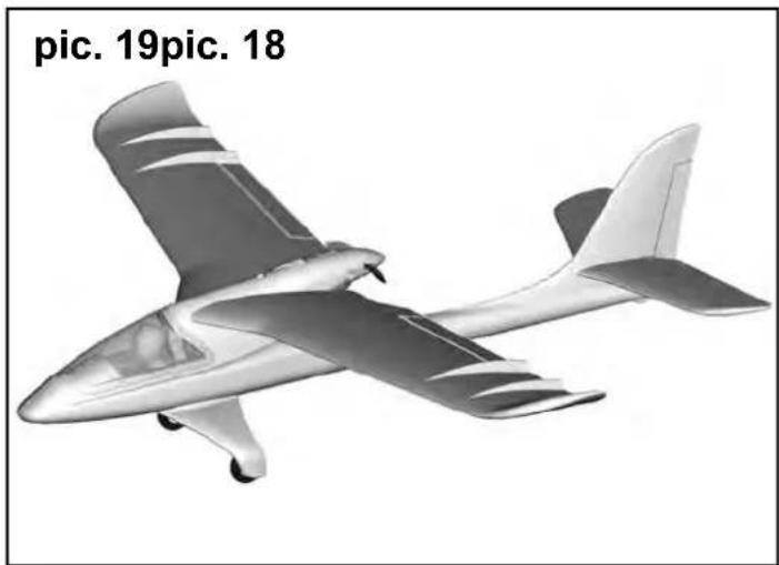
natural_image
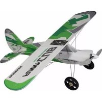
Illustration of a small propeller airplane (no text or symbols on the aircraft body)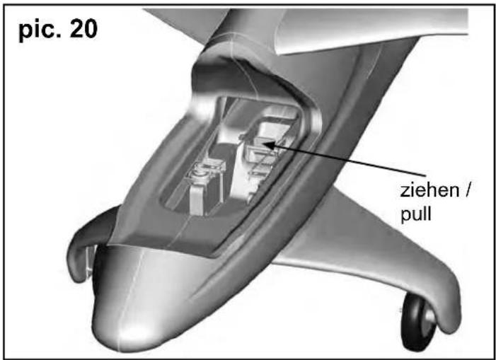
natural_image
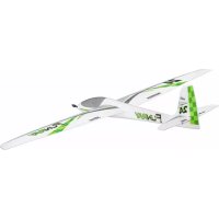
Illustration of three propeller aircraft in flight, shown from different angles (no text or symbols on the aircraft themselves)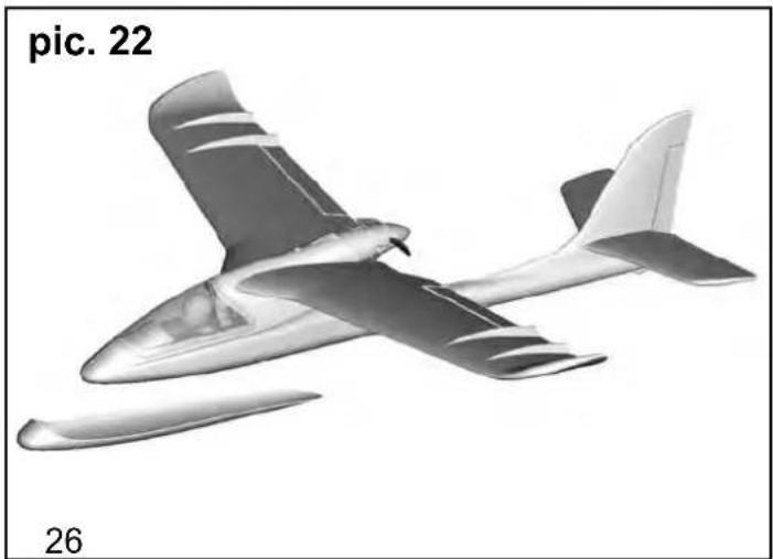
natural_image
Illustration of a small aircraft in flight, labeled 'pic. 22' and '26' (no other text or symbols)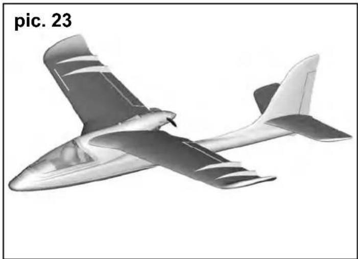
natural_image
Illustration of a model airplane in flight, labeled 'pic. 23' (no other text or symbols)7.3 Patin de protection (pic. 22&23):
Rep. Nbr. Désignation
1
1 Verrière
natural_image
Side profile illustration of a futuristic aircraft with visible tail and fuselage, labeled B (no text or symbols on the aircraft itself)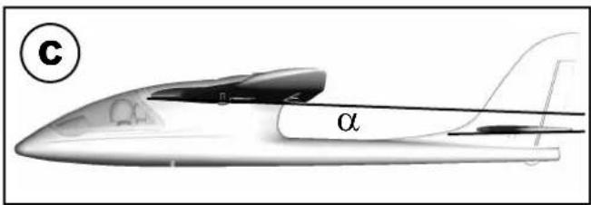

natural_image
Diagram showing a mechanical assembly with a pin, two circular components, and a propeller-like shape with rotational arrows (no text or symbols)Rischi residui
natural_image
Side profile illustration of a stylized aircraft or aircraft with tail fin and fuselage, labeled with letter B (no text or symbols on the diagram itself)
natural_image
Diagram showing two mechanical components: a square plate with circular holes and a propeller with directional arrows (no text or symbols)
natural_image
Symbolic illustration of transmission towers crossed out by a diagonal line, representing power or signal protection (no text present)
natural_image
Weather icon showing lightning bolt over cloud and rain (no text or symbols)Otros riesgos
natural_image
Side profile illustration of a stylized aircraft or aircraft with visible tail and fuselage, labeled 'B' in top-left corner (no text or symbols on the aircraft itself)
natural_image
Diagram showing a mechanical setup with a pin, circular components, and a propeller-like shape with rotational arrows (no text or symbols)Fuselage and fi n, excl. electronics /
natural_image
3D rendered model of a streamlined aircraft with visible propeller and fuselage (no text or symbols)# 22 4317
Tragfl ächen
wing set
Ailes
Ali
Alas
natural_image
3D rendered model of a gray plastic component with cutouts and internal grooves (no text or symbols)# 22 4315
Kabinenhaube
Canopy
Verrière
Capottina
Cabina
natural_image
Two 3D-rendered mechanical parts, one open and one closed, shown without any text or symbols.# 22 4318
Höhenleitwerkssatz
tailplane set
natural_image
Two technical illustrations: one showing a mechanical component with threaded end, the other a conical tip (no text or symbols)# 33 2308
natural_image
Two gray rectangular blocks on a white background (no text or symbols)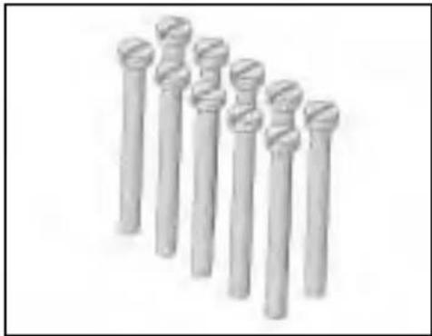
natural_image
Row of seven identical cylindrical objects with textured surfaces, no visible text or symbols683112
Klettband
Hook-and-loop tape
Bande crochetée
Velcro adesivo
Velcro
# 70 3457
Twin control surface horn with swivel connector
natural_image
Two abstract geometric shapes, one gray and one black, arranged diagonally (no text or symbols)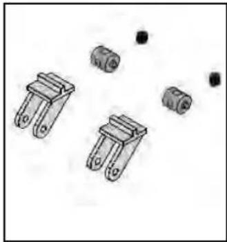
natural_image
Illustration of four mechanical components with mounting holes and small black dots (no text or symbols)# 33 3120
natural_image
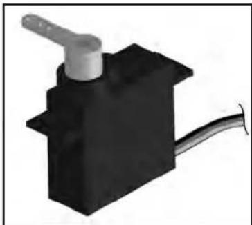
3D rendering of a small electric motor with black and gray wires, no visible text or symbols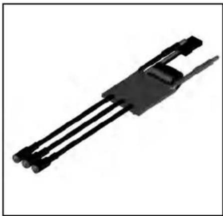
natural_image
Black mechanical component with three parallel rods and a clip, isolated on white background (no text or symbols)# 65112
Servo MS-12015
# 15 7321
Akku / Battery / Li-BATT FX
3/1-950 (M6)
natural_image
3D rendering of a black mechanical component with a white handle and cable (no text or symbols visible)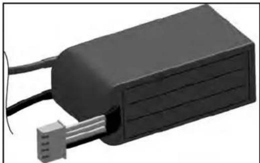
natural_image
3D rendering of a black rectangular electronic device with wires and a connector (no visible text or symbols)Tuning

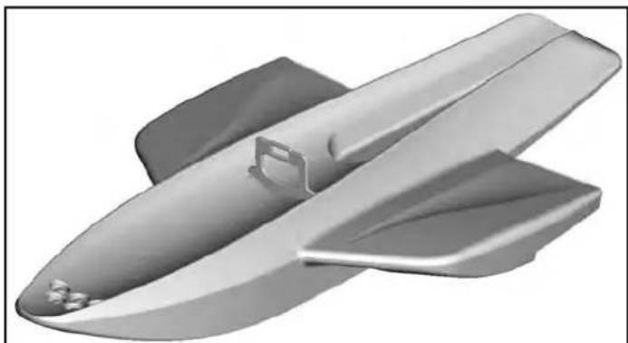
# 22 4327
Fahrwerkssatz /
Undercarriage set /
natural_image
Metal aircraft fuselage with two wheels, shown in grayscale (no text or symbols)# 22 4329
Landeschutzkufe /
Landing skid /
Patins /
natural_image
3D rendered image of a streamlined, elongated object with smooth shading and no visible text or symbols# 65165
Querruder-Upgradeset /
Aileron upgrade set /
Aileron Upgrade-Set /
Alettone Upgrade-Set /
natural_image
Exploded view of mechanical components including springs, actuators, and linkages (no text or symbols visible)# 22 4328
Schwimmersatz /
Floats set /
Flotteurs /
Set galleggianti /
Kit de fl otadores