USER MANUAL AF280170 GAGGENAU
Operating instructions:
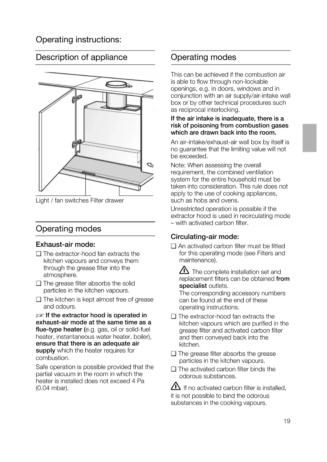
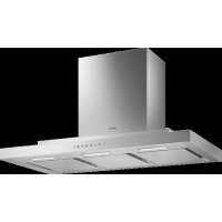
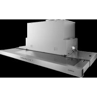
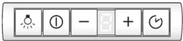
Description of appliance
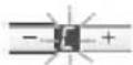
Light / fan switches Filter drawer
Operating modes
Exhaust-air mode:
The extractor-hood fan extracts the kitchen vapours and conveys them through the grease filter into the atmosphere.
The grease filter absorbs the solid particles in the kitchen vapours.
The kitchen is kept almost free of grease and odours.
If the extractor hood is operated in exhaust-air mode at the same time as a flue-type heater (e.g. gas, oil or solid-fuel heater, instantaneous water heater, boiler), ensure that there is an adequate air supply which the heater requires for combustion.
Safe operation is possible provided that the partial vacuum in the room in which the heater is installed does not exceed 4 Pa (0.04 mbar).
Operating modes
This can be achieved if the combustion air is able to flow through non-lockable openings, e.g. in doors, windows and in conjunction with an air supply/air-intake wall box or by other technical procedures such as reciprocal interlocking.
If the air intake is inadequate, there is a risk of poisoning from combustion gases which are drawn back into the room.
An air-intake/exhaust-air wall box by itself is no guarantee that the limiting value will not be exceeded.
Note: When assessing the overall requirement, the combined ventilation system for the entire household must be taken into consideration. This rule does not apply to the use of cooking appliances, such as hobs and ovens.
Unrestricted operation is possible if the extractor hood is used in recirculating mode with activated carbon filter.
Circulating-air mode:
An activated carbon filter must be fitted for this operating mode (see Filters and maintenance).
The complete installation set and replacement filters can be obtained from specialist outlets.
The corresponding accessory numbers can be found at the end of these operating instructions.
The extractor-hood fan extracts the kitchen vapours which are purified in the grease filter and activated carbon filter and then conveyed back into the kitchen.
The grease filter absorbs the grease particles in the kitchen vapours.
The activated carbon filter binds the odorous substances.
If no activated carbon filter is installed, it is not possible to bind the odorous substances in the cooking vapours.
Important notes:
The Instructions for Use apply to several versions of this appliance. Accordingly, you may find descriptions of individual features that do not apply to your specific appliance.
This extractor hood complies with all relevant safety regulations.
Repairs should be carried out by qualified technicians only.
Improper repairs may put the user at considerable risk.
Before using your appliance for the first time, please read these Instructions for Use carefully. They contain important information concerning your personal safety as well as on use and care of the appliance.
- Please retain the operating and installation instructions for a subsequent owner.
Do not use the appliance if damaged.
The appliance is not intended for use by young children or infirmed persons without supervision.
Young children should be supervised to ensure they do not play with the appliance.
If the connecting cable for this appliance is damaged, the cable must be replaced by the manufacturer or his customer service or a similarly qualified person in order to prevent serious injury to the user.
The appliance may be connected to the mains by a qualified technician only.
Dispose of packaging materials properly (see Installation instructions).
Light bulbs must always be fitted when the extractor hood is in use.
Defective bulbs should be replaced immediately to prevent the remaining bulbs from overloading.
Never operate the extractor hood without a grease filter.
Overheated fat or oil can easily catch fire.
If you are cooking with fat or oil, e.g. chips, etc., never leave the cooker unattended.
Do not flambé food directly under the extractor hood.
Risk of grease filter catching fire due to flames.
Restrictions apply to the use of the extractor hood over a solid-fuel burner (coal, wood, etc.). (See Installation instructions).
Gas hobs / gas cookers
Always use gas hobs in a proper and safe manner.
Important:
The flames from the gas hob must always be covered by pots or pans.
The intense heat generated by the gas! flames could cause damage to the extractor hood.
The most effective method of removing vapours produced during cooking is to:
Switch the ventilator ON as soon as you begin cooking.
Switch the ventilator OFF a few minutes after you have finished cooking.
Switching on appliance: Press the ① or ^+ button.
The fan starts at Setting
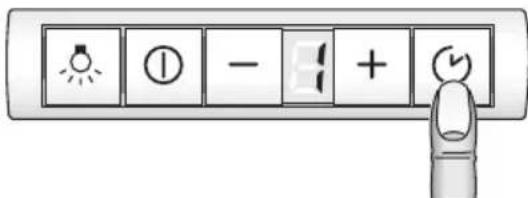
Switching on the fan settings/intensive setting:
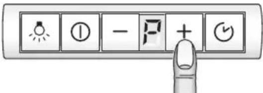
- To increase the fan settings or switch on the intensive setting , press the + button.
The intensive setting operates at maximum power which should be used only briefly. If the intensive setting is not switched off manually, the fan automatically switches back to Setting after 10 minutes.
- To switch off the intensive setting or switch back to fan settings 3 -2 - and switch off the extractor hood completely, press the button.

Intermittent ventilation
Used for ventilating the kitchen at hourly intervals at the lowest fan setting, round the clock.
Switching on appliance:
Press the button and insert the filter drawer.
The fan runs for 5 minutes at Setting, then switches off for 55 minutes. This process is repeated every hour.
Switching off: Press the button.
Switching off:
There are 2 different ways of switching off the appliance.
Switching off directly:
Press the 0 button.
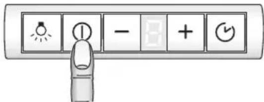
Important: All fan functions are switched off.
Switching off appliance with fan run-on:
Insert filter drawer all the way. The fans operate in the last switched-on stage for around another 10 minutes and then switch off.
If the intensive setting is switched on when the filter drawer is inserted, the intensive setting automatically switches back during run-on.
If intermittent ventilation is switched on, it continues operating normally following run-on.
Light
The light can be used at any time, even when the appliance has been switched off.
Switching on/off: Press the button.
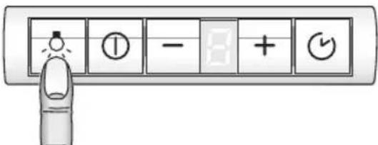
Adjusting the brightness:
Hold down the button until the desired brightness is obtained.
Special functions
Switching on the light automatically, e.g. via a timer:
Fan and light must be switched off.
Switching on:
Simultaneously press the - and buttons.

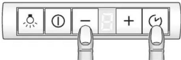
After approx. 3 seconds the light switches on to acknowledge the setting.
Switching off:
Repeat the process with the light switched on.
After approx. 3 seconds the light switches off to acknowledge the setting.
Grease filters:
Metal-mesh filters are used to trap the grease particles in the cooking vapours.
The filter mats are made from noncombustible metal.
Caution:
As the filter becomes more and more saturated with grease, there is an increased risk of fire and the function of the extractor hood may be impaired.
Important:
By cleaning the metal grease filters at appropriate intervals, the possibility of them catching fire as a result of a build-up of heat such as occurs when deep-fat frying or roasting is taking place, is reduced.
Saturation indicator:
When the grease filters reach saturation point, an acoustic signal is sounded for 6 seconds after the fan has switched off, and an appears in the display. The grease filters should be cleaned straight away.
The filters can be cleaned in a dishwasher. However, they may become slightly discoloured.
Important:
Do not wash highly saturated metal-mesh grease filters with other utensils.
If cleaning the filters by hand, soak them in a hot soap solution. Then brush the filters, rinse thoroughly and leave to drain.
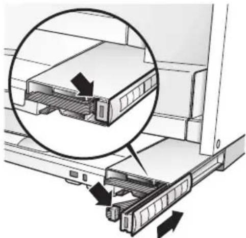
Warning: The halogen bulbs must be switched off and cool.
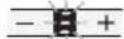
- Pull the filter drawer all the way out.
- Depress the catches at the rear of the grease filter and remove the grease filter.
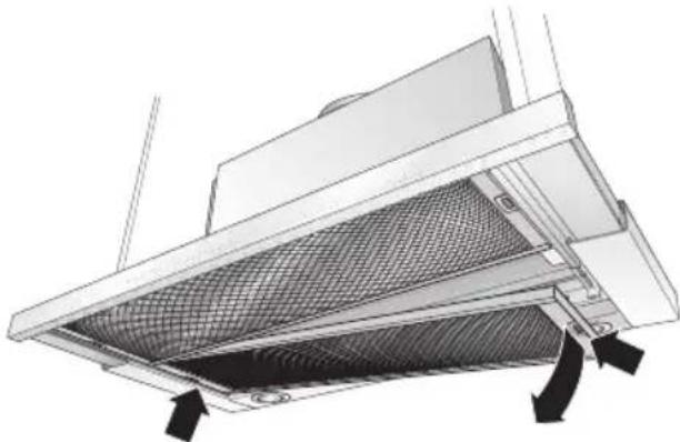
- Depress both catches at the front of the grease filter and remove the grease filter.
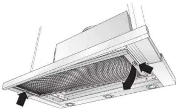
- Clean the filters.
- Insert the clean filters back into the hood.
- Cancel the display.
Press the ① button for at least 3 seconds. The display then goes out.
Activated carbon filter:
For neutralizing odours in recirculating mode.
Caution:
As the filter becomes more and more saturated with grease, there is an increased risk of fire and the function of the extractor hood may be impaired.
Important:
Change the activated carbon filter promptly to prevent the risk of fire from the accumulation of heat when deep-fat frying or roasting.
Inserting the filter:
Warning: The halogen bulbs must be switched off and cool.
- Remove the metal filters (see "Removing and inserting the metal grease filters").
- Insert the activated carbon filter.
- Engage the catches at both sides.
- Insert the metal-mesh grease filters (see "Removing and inserting the metal-mesh grease filters").
- Cancel the display.
Press the ① button for at least 3 seconds. The display then goes out.
Saturation indicator:
When the activated carbon filter is saturated, an acoustic signal is emitted for 6 seconds when the fan has switched off and is displayed. The activated carbon filter should then be replaced immediately.
Removing the filter:
Warning: The halogen bulbs must be switched off and cool.
- Remove the metal-mesh filters.
- Depress the catches on both sides of the filter and remove the activated carbon filter.
- Replacing the activated carbon filter:
A replacement filter can be obtained from any authorized dealer (see optional accessories).
Use original filters only.
This will ensure maximum performance.
- Insert the grease filters.
Disposing of the old activated carbon filter:
- Activated carbon filters do not contain any pollutants and can be disposed of with domestic refuse.
Cleaning and care
Isolate the extractor hood by pulling out the mains plug or switching off the fuse.
- When cleaning the grease filters, remove grease deposits from accessible parts of the housing. This prevents the risk of fire and ensures that the extractor hood continues operating at maximum efficiency.
Clean the extractor hood with a hot soap solution or a mild window cleaner.
Do not scrape off dried-on dirt but wipe off with a damp cloth.
Do not use scouring agents or abrasive sponges.
Note: Do not use alcohol (spirit) on plastic surfaces, as dull marks may appear.
Caution: Ensure that the kitchen is adequately ventilated. Avoid naked flames!
Clean the operating buttons with a mild soapy solution and a soft, damp cloth only. Do not use stainless-steel cleaner to clean the operating buttons.
Stainless steel surfaces:
Use a mild non-abrasive stainless steel cleaner.
Clean the surface in the same direction as it has been ground and polished.
Do not use any of the following to clean stainless steel surfaces: abrasive sponges, cleaning agents containing sand, soda, acid or chloride!
Aluminium and plastic surfaces:
Use a soft, non-linting window cloth or micro-fibre cloth.
Do not use dry cloths.
Use a mild window cleaning agent.
Do not use aggressive, acidic or caustic cleaners.
Do not use abrasive agents.
Replacing the light bulbs
- Switch off the extractor hood and pull out the mains plug or switch off the electricity supply at the fuse box.
When switched on, the halogen bulbs become very hot. Even for some time after the bulbs have been switched off there is still a risk of burns.
- Remove the bulb ring with a screwdriver or similar tool.
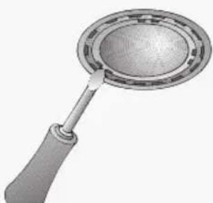
- Replace the halogen light bulb (conventional halogen bulb, 12 Volt, max. 20 Watt, G4 bulbholder). Caution: Plug-in bulbholder. Take hold of the bulb with a clean cloth.
- Re-insert the bulb ring.
- Restore the power by inserting the mains plug or switching on the fuse.
Note: If the light does not function, check that the bulbs have been inserted correctly.
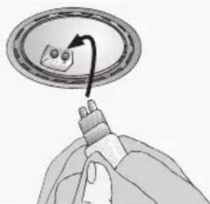
Moving the operating unit
You can move the operating unit from the middle of the filter drawer to the left or right side.
The operating unit can also be fitted at the front in a handle moulding available as an optional accessory or in the enclosed handle moulding.
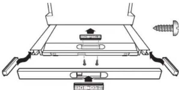
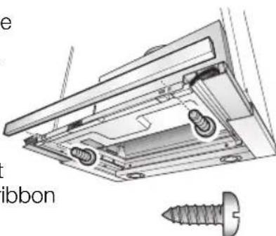
- Loosen the 2 screws from below.
- Remove the operating unit and disconnect the plug from the ribbon cable.
- Remove the side cover from the filter drawer.
- Connect the plug of the side ribbon cable to the operating unit.
- Insert the operating unit into the side of the filter drawer.
Insert the excess ribbon cable.
- Insert the cover into the middle of the filter drawer and screw on the cover from below with 2 screws.
Setting the saturation indicator
If the operating mode is to be switched over (exhaust air/circulating air mode), the saturation indicator for the filters must also be switched over (see Installation instructions).
Faults
If or is displayed:
See "Filters and maintenance" Section.
Isolate the extractor hood for approx. 1 minute by pulling out the mains plug or switching off the fuse. Then switch on again..
If you have any questions or if a fault occurs, please call Customer Service.
(See list of Customer Service representatives).
When you call, please quote the following:
E-Nr.
FD
Enter the numbers in the above box. The numbers can be found on the rating plate inside the extractor hood following removal of the grease filters.
Old appliances are not worthless rubbish. Valuable raw materials can be reclaimed by recycling old appliances. Before disposing of your old appliance, render it unusable.
- You received your new appliance in a protective shipping carton. All packaging materials are environmentally friendly and recyclable. Please contribute to a better environment by disposing of packaging materials in an environmentally-friendly manner.
Please ask your dealer or inquire at your local authority about current means of disposal.
The extractor hood can be used in exhaust air or circulating air mode.
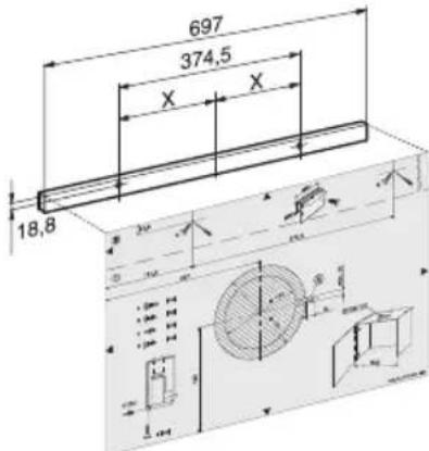
Always mount the extractor hood over the centre of the hob.
Minimum distance between electric hob and bottom edge of extractor hood: 430 mm, Fig. 1.
When installing gas hotplates, comply with the relevant national statutory regulations (e.g. in Germany: Technische Regeln Gasinstallation TRGI).
Always comply with the currently valid regulations and installation instructions supplied by the gas appliance manufacturer.
Only one side of the extractor hood may be installed next to a high-sided unit or high wall. Gap at least 300~mm
The installation of the extractor hood above gas cooking devices, at a minimum height of 650~mm - Fig. 1 - is permitted provided that the following nominal heat loads (Hs) are not exceeded:
Gas cookers Load of one hotplate max. 3.0 kW Load of all hotplates max. 8.3 kW Load of the oven max. 3.9 kW
Gas hobs Load of one hotplate max. 3.9 kW Load of all hotplates max.11.3 kW
Gas ceramic hotplate The nominal heat load specifications do not apply to closed gas ceramic hobs. Always observe the specifications of the hob manufacturer.
Solid-fuel cookers The maximum nominal heat loads and the minimum distance are the same as for gas cookers.
The extractor hood must not be installed over a solid fuel cooker - a potential fire hazard (e.g. flying sparks) - unless the cooker features a closed, non-removable cover and all national regulations are observed.
The smaller the gap between the extractor hood and hotplates, the greater the likelihood that droplets will form on the underside of the extractor hood.
Exhaust-air mode
The exhaust air is discharged upwards through a ventilation shaft or directly through the outside wall into the open.
Exhaust air must not be discharged via a smoke or exhaust gas flue which is already in use or via a shaft which is used for ventilating rooms in which fireplaces are located.
Discharge exhaust air in accordance with official and statutory regulations (e.g. national building regulations).
Discharge of air into smoke or exhaust air flues which are not in use requires the consent of a heating engineer.
If the extractor hood is operated in exhaust-air mode at the same time as a flue-type heater (e.g. gas, oil or solid-fuel heater, instantaneous water heater, boiler), ensure that there is an adequate air supply which the heater requires for combustion.
Safe operation is possible provided that the partial vacuum in the room in which the heater is installed does not exceed 4 Pa (0.04 mbar).
This can be achieved if the combustion air is able to flow through non-lockable openings, e.g. in doors, windows and in conjunction with an air supply/air-intake wall box or by other technical procedures such as reciprocal interlocking.
If the air intake is inadequate, there is a risk of poisoning from combustion gases which are drawn back into the room.
An air-intake/exhaust-air wall box by itself is no guarantee that the limiting value will not be exceeded.
Note: When assessing the overall requirement, the combined ventilation system for the entire household must be taken into consideration. This rule does not apply to the use of cooking appliances, such as hobs and gas cookers.
The extractor hood can be used without restriction in circulating air mode - with an activated carbon filter.
For exhaust air mode a one-way flap should be installed in the extractor hood unless already installed in the exhaust air pipe or wall box.
If a one-way flap is not enclosed with the extractor hood, you purchase one from your dealer.
If the exhaust air is conveyed through the outside wall, a telescopic wall box should be used.
Short, smooth exhaust pipe.
As few bends as possible.
Pipe diameter as large as possible (ideally 150~mm dia.) and wide pipe bends.
If long, rough exhaust-air pipes, many pipe bends or smaller pipe diameters are used, the air extraction rate will no longer be at an optimum level and there will be an increase in noise.
Round pipes
Short exhaust air pipe:
inside diameter min. 120mm
Longer exhaust air pipe:
inside diameter min. 150 mm.
Flat ducts must have an inside cross-section equivalent to the round pipes.
There should be no sharp bends.
120 mm dia. approx. 113 cm
150 mm dia. approx. 177 cm
If pipe diameters differ, insert strip.
Ensure that there is an adequate air supply for exhaust air mode.
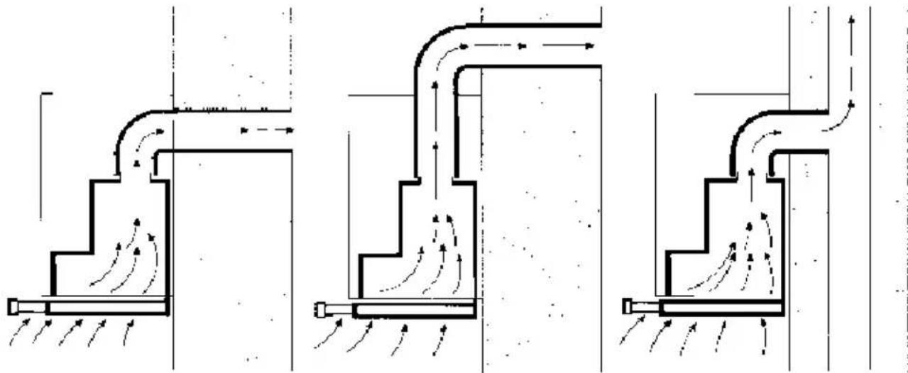
Exhaust air directed backwards:
Only possible inside tall wall cupboards depending on the size of the exhaust air pipe.
Make a hole in the rear panel of the wall cupboard, cutting out a notch for the power supply cable.
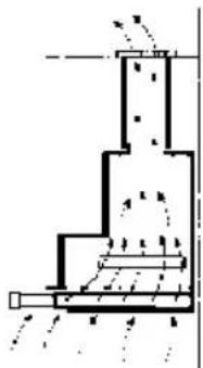
Exhaust air directed upwards:
- Make a hole in the top of the wall cupboard, cutting out a notch for the power supply cable.
- template ① enclosed -.
- If fitted, cut out the cupboard base to a min. depth of 270mm over the entire width.
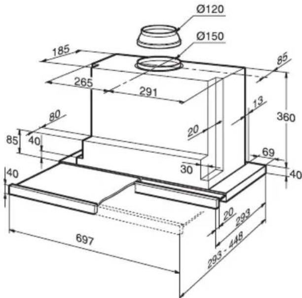
Connecting a 150 mm exhaust pipe:
- Attach the exhaust pipe directly to the air connector.
Connection of 120mm exhaust air pipe:
- Attach enclosed reducing connector to the air outlet.
Holes in the air outlet must be sealed.
- Attach exhaust air pipe to the reducing connector.
Circulating-air mode
- With activated carbon filter if exhaust-air mode is not possible.
The complete installation set can be obtained from specialist outlets.
The corresponding accessory numbers can be found at the end of these operating instructions.
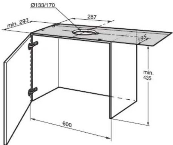
Preparing the wall cupboard
This extractor hood is designed to be installed in a wall cupboard with the following dimensions:
width: 600 mm
depth: 293 to 350~mm
height: min. 435 mm.
If the cupboard is deeper than 293~mm the extractor hood can be moved back, e.g. to put a spice rack in front of the extractor hood.
To do this, place the template further back.
Ensure that the cupboard is stable both during and after installation, even if fitted at the end of a row of kitchen units.
Do not install the extractor hood at the end of the kitchen line.
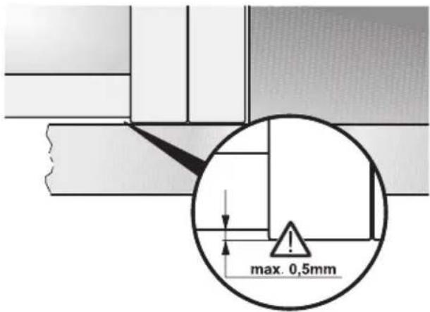
Align the cupboards exactly. If required, place the side cupboards flush underneath.
The side panels must not project over the base of the adjacent unit by more than 0.5mm
Weight in kg:
| Exhaust air Circulating air |
| 13,5 14,0 | |
We reserve the right to construction changes within the context of technical development.
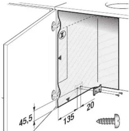
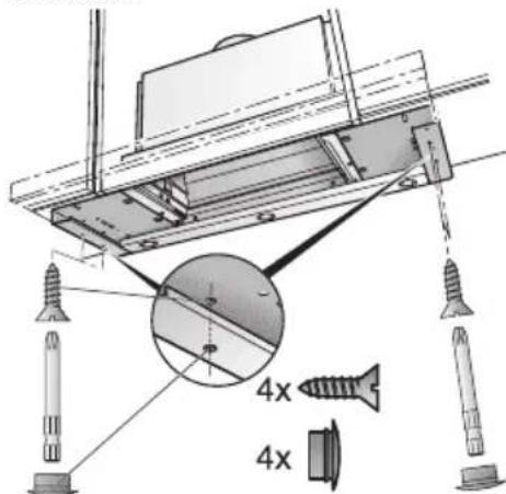
- Mark two attachment points on both the right and left inside faces of the cupboard and make holes with a bradawl.
When you drill:
2 mm diameter - max. 10 mm in depth.
Use the enclosed template to mark the attachment points.
-
Screw on both attachment plates.
-
Attach the door to the cupboard and align.
Observe the minimum distance between hotplates and extractor hood! Fig. 1.
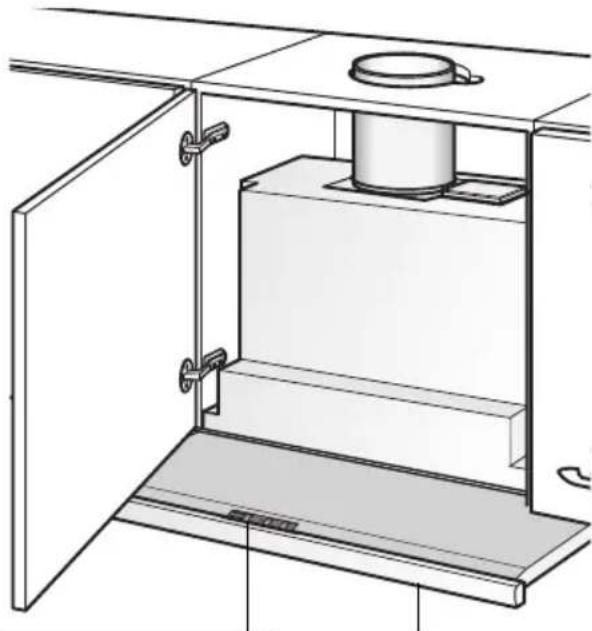
Fitting into wall cupboard
Check door alignment and readjust if necessary.
- Remove grease filter (see Operating instructions).
- Lift the extractor hood into the cupboard from below until both fixing lugs have locked firmly into position.
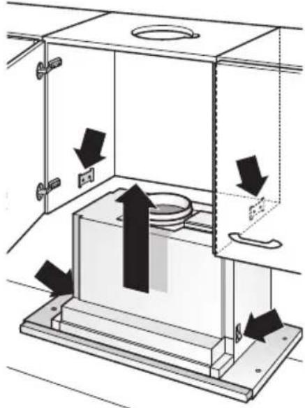
- Screw in the adjusting screws by hand until the extractor hood is situated on the base of the cupboard.
Align the extractor hood in the cupboard.
Carefully tighten both fastening screws.
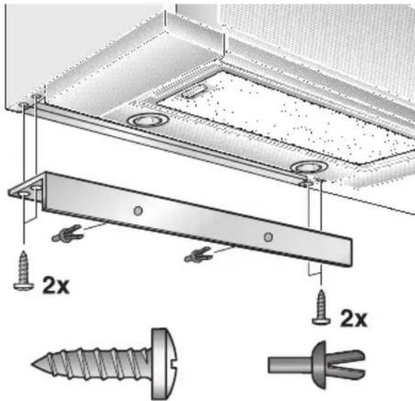
- Also attach the extractor hood to the left and right wall cupboards with 2 screws each side. First make pilot holes with a bradawl.
- Seal the holes with 2 stoppers each on the left and right.
- If required, shorten the wall cover to the required dimension (e.g. saw off). Attach the wall cover with the enclosed clips. Screw the wall cover to the wall cupboard.
- Feed the mains connection cable out of the cupboard.
- Connect the pipes in the wall cupboard. - If required, attach the air hose to the cupboard ceiling -
- Re-insert grease filter (see Operating instructions).
Fitting into wall cupboard
Note: The extractor hood housing can be clad inside the wall cupboard (e.g. with chipboard).
If so, observe the following:
The intermediate base must not be placed on the extractor hood housing.
Never attach cladding to the housing.
□ Provide access for customer service.
If the extractor hood is to be installed further back in the cupboard, the stops for the filter drawer can be moved forwards.
To do this, undo the screws, move the stops and retighten the screws.
Moving the operating unit:
See Operating instructions.
Attaching the handle moulding:
A handle moulding must be attached to the filter drawer.
This handle moulding may be a wooden strip which matches the kitchen units or a handle moulding available as an optional accessory.
- Using the enclosed template mark the attachment points on the wooden strip and make holes with a bradawl. When you drill: 2 mm dia - max. 10 mm in depth.
- Align handle moulding and screw to the appliance.
Do not pinch the ribbon cable.
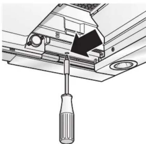
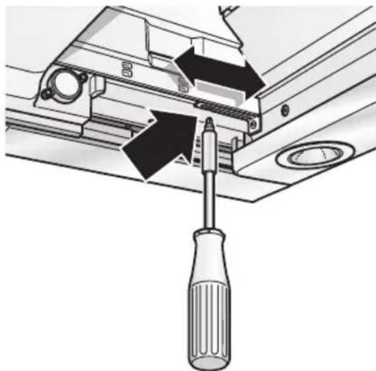
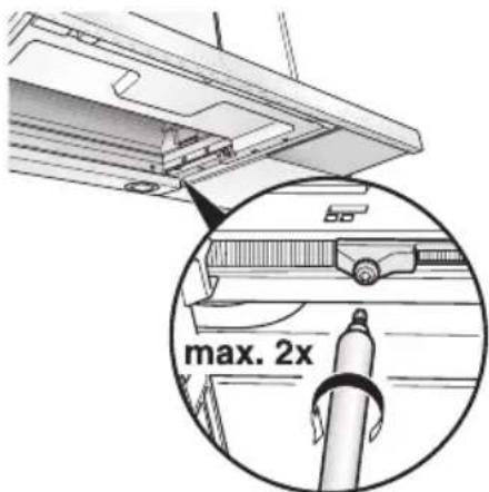
Re-adjusting the limit switch:
- Check whether the extractor hood switches off when the filter drawer is inserted.
- If the extractor hood does not switch off, re-adjust the limit switch.
- Unscrew the screw in small steps - max. 2 revolutions.
WARNING: THIS APPLIANCE MUST BE EARTHED
IMPORTANT: Fitting a Different Plug:
The wires in the power cord are colour-coded as follows:
Green and Yellow - Earth
Blue - Neutral
Brown-Live
If you fit your own plug, the colours of these wires may not correspond with the identifying marks on the plug terminals.
Proceed as follows:
- Connect the green and yellow (Earth) wire to the terminal in the plug marked 'E' or with the symbol (±) , or coloured green or green and yellow.
- Connect the blue (Neutral) wire to the terminal in the plug marked 'N' or coloured black.
- Connect the brown (Live) wire to the terminal marked 'L', or coloured red.
The extractor hood may be connected to a correctly installed earthed socket only. Attach the earthed socket near the extractor hood in an accessible position.
The earthed socket should be connected via its own power circuit.
If appliances do not feature the OFF delay function, the indicator may start flashing when the extractor hood has been switched off for several hours via a separate switch, even though the grease filters are not yet saturated.
(See instructions for use, section on filter and maintenance).
Electrical specifications:
These can be found on the rating plate inside the appliance following removal of the filter frames.
Before carrying out repairs, always isolate the appliance.
Length of the connection cable: 1.30m
If permanent connection is required:
The extractor hood may only be connected by an electrician registered with the local electricity board.
A disconnecting device must be provided on the installation side. Switches with a contact opening of more than 3mm and all-pole disconnection are regarded as disconnecting devices. These include LS switches and contactors.
This extractor hood complies with EU regulations on interference suppression.
Removal from the wall cupboard
- Disconnect from power.
- Disconnect pipes.
- Remove filters.
- Undo right and left fixing screws until the extractor hood cannot drop any further.
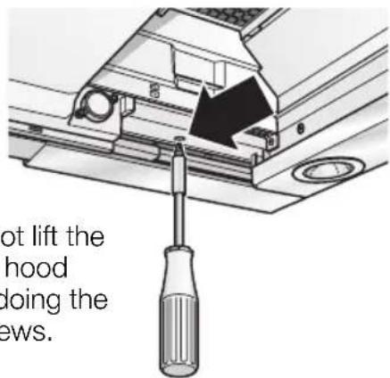
Do not lift the extractor hood when undoing the fixing screws.
- Raise the extractor hood briefly until the fixing lugs detach and the appliance can be lowered.
Fastening screws may project. When raising the extractor hood, do not force in the filter drawer.
- Preparing for re-installation: Screw in the left and right fixing screws until the lugs are pressed out at the sides.
Switching over from exhaust air to circulating air mode
Switching the electronic control system to circulating air mode:
The extractor hood has been set to exhaust air mode at the factory.
Before the mode can be changed, the extractor hood must have been connected and should be switched off.
- Press and hold down the ① button.
- Press the button for approx. 3 seconds.
□A is displayed.
- Release the buttons.
The display goes out shortly afterwards.
Resetting to exhaust-air mode:
- Repeat the procedure.
□ A is displayed.
- Release the buttons.
The display goes out shortly afterwards.
Mode d'emploi:
Let op: plugfitting.
A Anything to do is not allowed.
ELeyETe TnV EuOuypaumTou epaiou,av XpeiaZetai EuOuypaumiotε K VEOU.
| Академicals
Академicals | Академicals |
| 13,5 14,0 | |
EnuuaooeTa yiaaayc kataoekunc oTa nlaiaTn TExvkiNpOoou.
Métatónion tou πδiou xειριαóu:
Bλ. Μθηγες χρήσς.
Sigma o Oynon Tou naxn aBns:
Tn oupouevn unofox n atou u e iAtpo npen va tonoetnthe evac nXnc laBnC.
O nnxns naibns mnpoei va evai evac Eulivoc nixnc nou taipiaz1e1 e Ta ennla kouicvac n evac nixnc naibns nou diatietai wc 16ik0 8xaptnma.
- XapaTe To eIouvaTToevo XVapia onueia oTepeewonC otov Eulivo nXn kai novTapet Ta e Ooubetai. Av diavoixtouv TpuNec TpuNavi: 2 mm- to noLu 10 mm baOoc.