
WR1994 - Refrigerator TRISTAR - Free user manual and instructions
Find the device manual for free WR1994 TRISTAR in PDF.
| Product Type | Wine Refrigerator (Wine Cabinet) |
| Brand | TriStar |
| Model | WR1994 |
| Storage Capacity | 61 bottles (standard), with sliding shelves (max 8 bottles) |
| Upper Zone Temperature Range | 12°C to 22°C (adjustable) |
| Lower Zone Temperature Range | 5°C to 12°C (adjustable) |
| Digital Display | Two digital tubes for each zone |
| Control Type | Electronic with +/- buttons and TEST function |
| Compressor | With operating LED indicator |
| Electric Heating | Built-in, with LED indicator |
| Activated Carbon Filter | Yes (replace every 6 months) |
| Shelves | Fixed storage shelves and sliding shelves |
| Power Supply | 220-240 V, 50 Hz, 16 A, grounded plug |
| Installation | On adjustable feet, rear space of 2 to 6 cm |
| Maximum Load per Shelf | 85 kg for storage shelf, 15 kg for sliding shelf |
| Interior Maintenance | Annual cleaning with water and mild detergent |
| Condenser Dusting | Twice a year |
| Child Safety | Instructions: do not allow children to climb, remove doors before disposal |
| Error Codes | E2 (upper zone sensor), E3 (lower zone sensor), E8 (excessive cold protection), E9 (overheating protection) |
| Repairs | Must be carried out by a qualified technician, leak check required |
| Disposal | Do not dispose of with household waste; take to a WEEE recycling point |
Frequently Asked Questions - WR1994 TRISTAR
User questions about WR1994 TRISTAR
0 question about this device. Answer the ones you know or ask your own.
Ask a new question about this device
Download the instructions for your Refrigerator in PDF format for free! Find your manual WR1994 - TRISTAR and take your electronic device back in hand. On this page are published all the documents necessary for the use of your device. WR1994 by TRISTAR.
USER MANUAL WR1994 TRISTAR
■MODELES: WR-1994 WR-1995
Note- 1
Thanks for choosing our product, please read this manual carefully before using it. This instruction manual is the universal-purpose version for the models of wine cabinet manufactured by our Co. The appearance of the units that you purchase might be slightly different from the ones described in the manual, but it does not affect your proper operations and usage. Please read carefully the sections corresponding to the specific model you choose, and keep the manual properly so as to facilitate your reference at later time.
■MODEL: WR-1994 WR-1995
Note- 1
Your wine cabinet- 2
Installing your wine cabinet- 3
Putting into service-Temperature settings- 5
Layout and storage
Routine maintenance- 9
Operating problems 10
NOTE

Note
- The parameter is subject to change without prior notice, the final data and circuit diagram is on rating label. Please pay attention to latest data.
- It's common that there are drips on the glass door when humidity in the air is high or the temperature different largely between inside of the cabinet and the environment temperature. Rub it clear with dry soft cloth will be OK.
- The film attached to the unit is to avoid scull and you can take it down if you do not like it.
- It is normal to frost on the inter-backside of the cabinet. The frost will melt naturally when the cabinet stops wording.
- If the appliance is broken and not be used for ever, don't throw it freely, send it to the recycle bin.
1-IMPORTANT SAFETY INSTRUCTIONS
You must always observe some basic precautions when using your wine cabinet, including: Only use your wine cabinet for the use intended, as described in this guide.
Never unplug the wine cabinet by pulling on the power cord, Grip the plug firmly and pull straight out to remove from wall socket.
Immediately repair or replace any worn or damaged cord, Never use a cord that is split on which shows signs of wear along its length or on its ends.
Do not allow children to climb on.sit on or stand on the wine cabinet, nor hang from its sheleves, They could damage the wine cabinet and injure themselves seriously. Do not use an extension cord.

DANGER
Risk of child entrapment. Before you throw away your old refrigerator or freezer:
- Take off the doors
- Leave the shelves in place so that children may not easily climb inside.
If the supply cord is damaged, it must be replaced by the manufacturer, its service agent or similarly qualified persons in order to avoid a hazard.
2-CONNECTING TO MAINS SUPPLY
The wine cabinet's power cord is equipped with a plug witch fits into any standard socket with earth connection, to prevent any risk of shock. Have the mains socket checked by a qualified Electrician to make sure it is actually connected to earth.
If this is not the case, you must have it replaced with a socket which is suitably earthed.
If the power cord is damaged, have it replaced by a qualified electrician to prevent any risk.
If the wall socket is not equipped with an earth connection, it is your responsibility and your duty to have it replaced with a suitably earthed wall socket, if the plug does not match your socket, you may have another fitted.

Note
- For your safety, wine cabinet must be correctly earthed
- New electrical cables and plugs should be fitted by a qualified electrician.
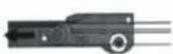
YOUR WINE CABINET
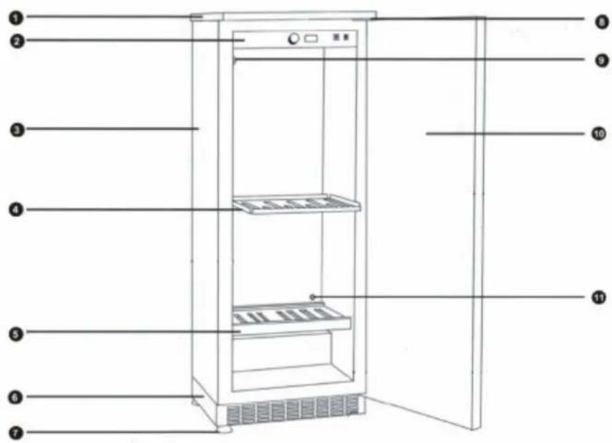
Removable Plate
Control Panel and Temperature Settings
Cabinet
Sliding shelf
Storage shelf
Front Ventilation Base
4 Adjustable Feet
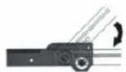
Hinge
Activated Charcoal Filter
10 Door
Free Ventilation Hole
INSTALLING YOUR WINE CABINET
- When you receive your cabinet, make sure when you unpack it there is no defect in its external appearance (from shocks, deformation, etc.).
-Open the door and check to see that the inside is complete (walls, shelves hinges, control panel, etc.)
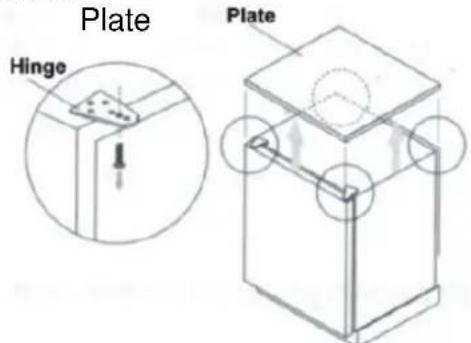
-If you wish to install your cabinet under a worktop, you will need to remove the top plate which is fixed from underneath by two front screws in the hinges and two screws behind in the angle brackets. Keep the two front screws if you wish to encase the unit under a worktop so as to fix it to existing worktop (see diagrams page 4)
-Now carry the cabinet to where you want to install it. Make sure the place selected is:
-away from any source of heat
-not too damp(laundry room, utility room, bathroom, etc.)
-on a stable level surface
- equipped with a power point(standard socket, rated voltage, 16A, connected to earth)
-Make sure the On/Off switch located on the right of the control panel is in the off position.
- Take out the mains lead and connect it as shown in section 3. Check the power point supply (fuses in, fuse amperage, circuit breaker working, You can if you wish use another appliance to check the power supply.)
- Adjust the four feet underneath the cabinet (screwing them up or unscrewing them) so that your cabinet is level (it is advisable to use a spirit level).
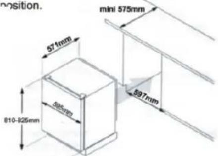
- Slide the cabinet into its final position, leaving a space of between 2 and 6cm between the wall and the rear wall of the cabinet, for installation under a worktop (Model 103), fix the cabinet to the worktop using two screws in the top hinges (see diagram below).
-Do not obstruct the front ventilation grille.
-Make a ventilation hole (flush-mounted grille) in the worktop (see diagram 4 below)
-Remove the protective materials from the inside of the cabinet.
-Remove the protective paper form the charcoal filter that you will find in the accessories pack, Form inside the cabinet, position the filter in the round box located in the top back of the cabinet.
-Arrange the shelves to suit your convenience (see section 6.)
- Wait 48 hours before switching the cabinet on so as to allow the fluids to settle.
NB: If ever you need to move the cabinet, do not tilt it at an angle of more that 45irc , and always on the side where the lead comes out.
The appliance must be positioned so that the plug is accessible.
INSTALLING YOUR WINE CABINET
103: Installation Diagram
- Remove the plate by unscrewing the 2 screws located under the 2 hinges (door open) and the 2 screws behind in the angle brackets.
Hinge
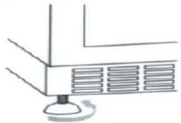
3. Adjust the 4 feet
4.
5. Slide the cabinet into its final position to final position.
6.
110mm
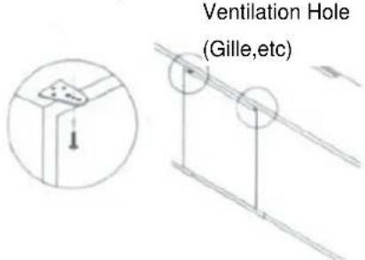
7. Screw the 2 screws through the hinges and into the worktop.
INSTALLING A UNT WITH A TECHNICAL DOOF
- Level the unit side the cabinet
- Open the door of the unit a 90irc angle.
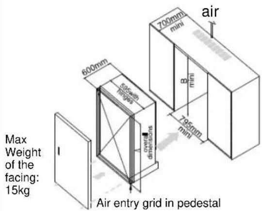
1-Drawing for unit placed on the floor.
- Fix the facing of the kitchen cabinet on the door of the unti (8 screws included).
- Be sure the gasket seals properly.
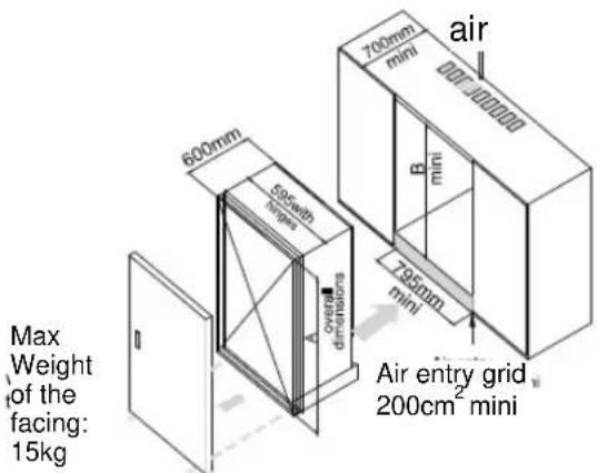
2-Drawing for unit placed in a cabinet
| Effective Volume A | mini(mm) | A mini(mm) | B mini(mm) |
| 3 | 815 | 830 | 915 |
| 188 | 1215 | 1230 | 1315 |
| 270 | 1615 | 1630 | 1715 |
Note:
A=Body+Pedestal(90mm)+Feet(20-35mm)
All around the appliance must have 100mm space.
PUTTING INTO SERVICE-TEMPERATURE SETTINGS
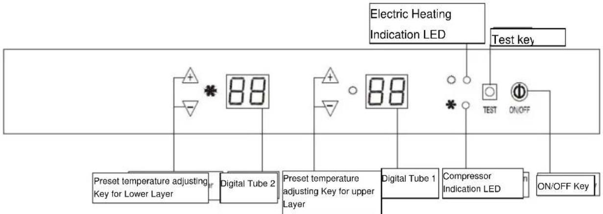
Digital Tube1: Indicate the current temperature or preset temperature of upper layer. When +/- Key is pressed, display on the digital tube flashes, indicating the preset temperature. If no temperature setting operation occurs within five seconds, the system will automatically return to the display of ambient temperature in the storage cabinet, with the accuracy of 1ircC(1ircT)
The introduction about malfunction code: E2 Faults of upper layer's cabinet temperature sensor.
The sensor is short circuit or open circuit.(10seconds later the system will close and this code will display. The buzzer will tweet every 2 seconds.)
E9 is Superheating protection. After compressor operating 4 hours under any condition, when the upper layer sensor detects the cabinet temperature no less than 25ircC (77ircF) , the buzzer will alarm and tweet every 2 seconds. When the detected cabinet temperature is >30ircC , "E9" malfunction code will display.
The Electrical Heating will close and compressor will go on working.(The buzzer will tweet every 2 seconds). When Upper layer sensor detects the cabinet Temperature reaches 21ircC , the system will restart automatically and the temperature will display normally.
Preset Temperature Adjusting Key for Upper Layer: Press this key to adjust the preset temperature of upper layer. Every time it is pressed, the preset temperature of upper layer is increased or decreased by 1ircC(1ircF) . Temperature setting range is 12ircC - 22ircC(54ircF - 72ircF)
Digital Tube2: Indicate the current temperature or preset temperature of lower layer. When +/- Key is pressed, display on the digital tube flashes, indicating the preset temperature. If no temperature setting operation occurs within five seconds, the system will automatically return to the display of ambient temperature in the storage cabinet, with accuracy of 1ircC(1ircF)
The introduction about malfunction code: E3 faults of lower layer's cabinet temperature sensor. The sensor is short circuit or open circuit.(10 seconds later the system will close and this code will display the buzzer will tweet every 2 seconds)
E8 is Supercooling protection. When the lower layer sensor detects the cabinet temperature reaches 3 irc C(37ircF) , the compressor will stop, but electrical heating keeps going on."E8"
Malfunction code will display. (The buzzer will tweet every 1 second). When the detected cabinet temperature is no less than 6ircC(43ircF) , the system will restart automatically and the temperature will display normally.
Preset Temperature Adjusting Key for Lower Layer: Press this key to adjust the preset temperature of lower layer. Every time it is pressed, the preset temperature of lower layer is increased or decreased by 1ircC(1ircF) . temperature setting range is 5ircC - 12ircC(41ircF - 54ircF)
Compressor Indicator LED: This LED comes on while the compressor is operating, and goes out when the compressor stops operation.
Electric Heating Indicator LED: this LED comes on during operation of electric heating device and goes out when electric heating device stops operation.
PUTTING INTO SERVICE-TEMPERATURE SETTINGS
TEST Key: If this Key is pressed in Standby state, the compressor and electric heating device will operate at the same time, and Compressor Indicator LED and Electric Heating Indicator LED will come on at the same time. When this key is released, the system returns to previous standby state. This key is invalid in operational state.
Notes:
1 There should be at least 5-minute interval between compressor stopping and starting again, the compressor should operate for at least five minutes after it is started up and then its operation can be stopped depending on actual conditions.
2. The temperature indicating range of Digital Tube 1 and Digital Tube 2 is 0ircC - 37ircC (32°F - 99°F). When the temperature is below 0ircC(32ircF) in the storage cabinet, indicated temperature is 000, and when the ambient temperature is above 37ircC(99ircF) in the storage cabinet, the indicated temperature is 37ircC(99ircF) .
3 the difference of temperature displayed on Digital Tube 1 and Digital Tube 2 should be above 5ircC(41ircF) .
4. The temperature setting range of upper layer (12ircC - 22ircC) and lower layer (5ircC - 12ircC) are effective when the ambient temperature is 32ircC , otherwise it would be difficult to reach the lowest setting temperature of upper layer and lower layer.
5.the difference between display temperature and setting temperature is ± 1.5ircC(3ircF) , when the cabinet temperature is balanced.
LAYOUT AND STORAGE
Your cabinet was designed to be flexible ,to be able to adapt to your requirements.
DIFFERENT TYPES OF LAYOU
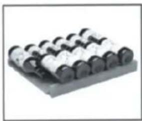
Storage Shelf Ref:AXL
Capacity:61bottles Max.Weight85kg
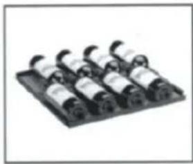
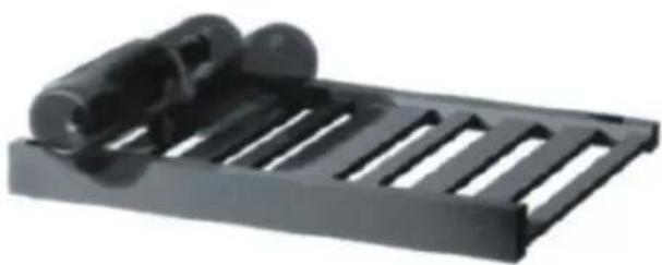
Sliding Shelf Ref:AXM
Capacity:8 bottles Max.Weight15kg
HOW TO USE YOUR STORAGE SHELF(AXL)
To store your Claret:
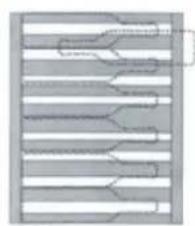
Top View
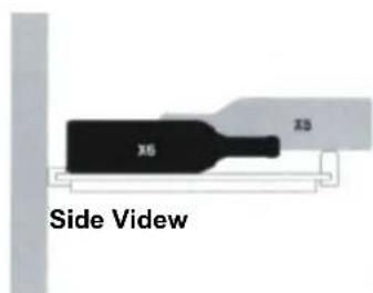
Back of Cabinet
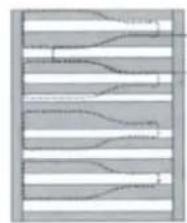
To store your Burgundy:
Top View
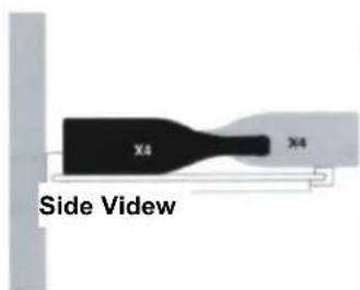
Back of Cabinet
Fitting shelf brackets (read carefully if you intend to modify your cabinet's shelf positions)
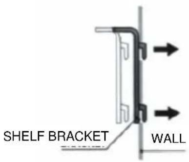
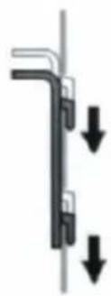
STORAGE SHELF
To move a storage shelf, first remove all bottles, then move the shelf brackets and make sure to fit them back into slots as shown below:
LAYOUT AND STORAGE
SLIDING SHELF
To move a sliding shelf, first remove all bottles, then remove the sliding shelf by sliding it towards you while lifting the front part, remove the sliding guides from the walls, while making sure not to mix up the right and left guides, then refit them as shown below:
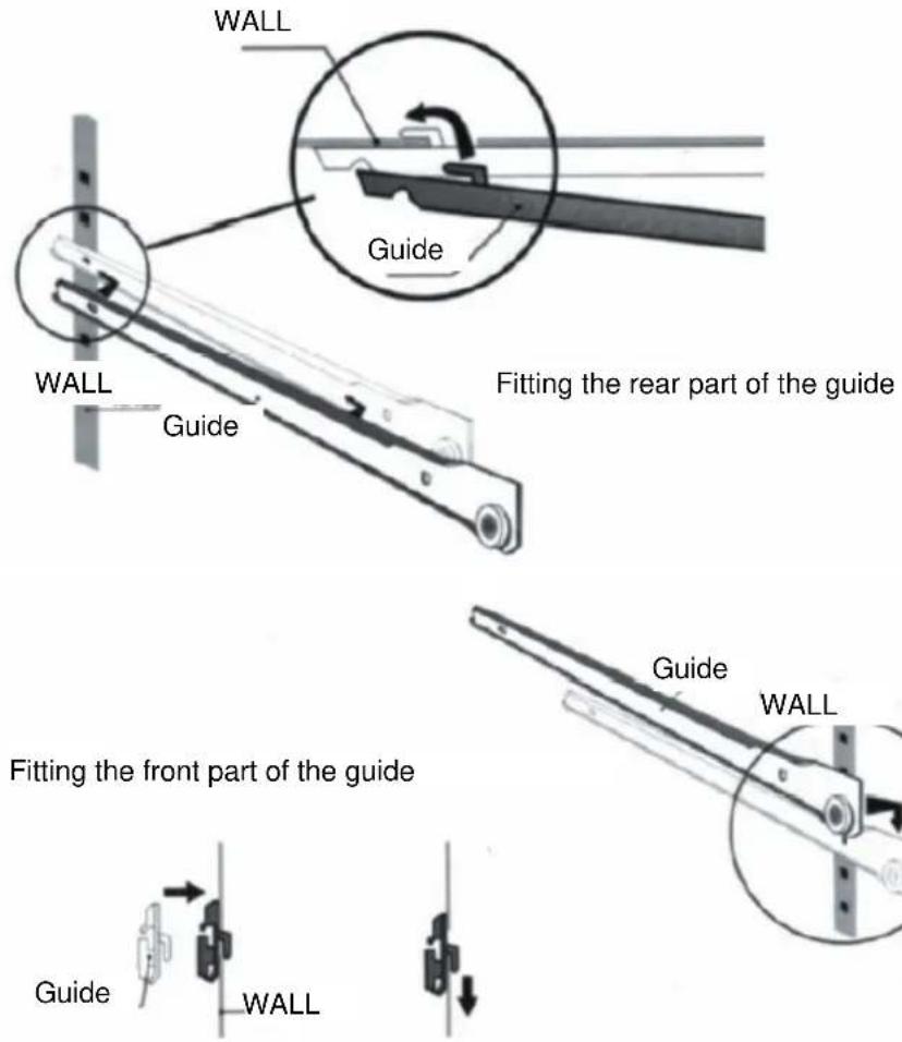
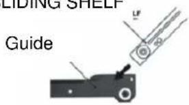
Then refit the sliding shelf as shown below:
SLIDING SHELF
LAYOUT AND STORAGE
RECOMMENDATIONS FOR LAYOUT AND STORAGE OF YOUR WINE CABINET
Your cabinet was designed to store a maximum number of bottles in total security, we recommend that you observe the tips below to optimize loading.
- Spread your bottles out as evenly as possible over the shelves, so that weight is not concentrated in one point. Also make sure your bottles do not touch the back of the cabinet, ore the step at bottom.
- Also make that bottles are not all grouped together at the top or bottom of the cabinet.
- Observe the loading instructions provided in section 6, according to the type of storage fixtures with which your cabinet is equipped, and never stack bottles on a sliding shelf.
- Never try to pull out more than one sliding shelf at a time.
PLEASE NOTE
Before modifying your cabinet's original configuration in any way, be sure to ask your dealer for advice.
ROUTINE MAINTENANCE
Your cabinet is easy to operate and has proven its reliability, it will provide long-lastlong satisfaction if you follow the simple maintenance and cleaning operations listed below.
- Replace the activated charcoal filter in our cabinet's upper ventilation hole half a year (your dealer keeps this accessory in stock).
- Remove dust from the condenser (metal screen on the back of the cabinet) twice year.
- Make sure the power cord is unplugged before cleaning the back of your cabinet, or before moving it.
- Clean the inside of your cabinet thoroughly once a year, after unplugging and unloading it (use water and a mild cleaning product, then rinse carefully).
To assure that your wine cabinet provides long-lasting service, you should check it regularly and inform your dealer if you note anything unusual.
NOTE:
Disposal of insulation materials: don't dispose by yourself. Please turn to national appointed waste recycle organization.
OPERATING PROBLEMS
START-UP
Compressor does not start even though the desired temperature is lower than the temperature in the room.
- Check the wall socket by plugging in any type of electrical device, and male sure that the on/off button in pressed.
- Press the TEST button and check that the two red and green indicator lights light up (in the standby status).
- If the compressor still does not start after steps 1 and 2, contact your dealer.
Compressor does not stop
- Place your hand on the condenser (metal screen at the back of your cabinet) to check its temperature contact your dealer if cold.
- If the condenser is hot, set the cold temperature as high as possible (as far as it will go clockwise) and make sure that the cold circuit operation indicator goes off, if the compressor does not stop, unplug the cabinet and contact your dealer.
DURING OPERATION
A digital tube display indicate a temperature below the temperature you set.
- check the temperature set-points
- check that the red hot circuit operation indicator light is on.
- Press the TEST button, and check that the two red and green indicator lights on the right side of the panel are on. If either step 1 or 3 is incorrect contact your dealer.
Digital tube display indicates a temperature above the temperature you set.
- check the temperature set-points.
- Check that the green cold circuit operation indicator light is on.
- Press the TEST button, and check that the two red and greed indicator lights on the right side of the panel are on, if either step 2 or 3 is incorrect contact your dealer.
Contact your dealer, if after adjusting set-points and testing hot and cold circuit indicator lights either of the two problems above are not corrected.
Note: the refrigeration unit must only be serviced by a refrigeration technician, who must check the circuit for leaks before putting back into service, any servicing of the electrical circuit must only be performed by an electrician.
NB: whatever the case, if your cabinet does not seem to be operating normally, unplug it and call your dealer.
Mobiletto per Vini
MODELO:WR-1994 WR-1995
Nota- 1
MODELO: WR-1994 WR-1995
Nota- 1
A sua garrafeira 2
Guidelines for protection of the environment
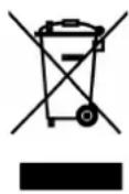
This appliance should not be put into the domestic garbage at the end of its useful life, but must be disposed of at a central point for recycling of electric and electronic domestic appliances. This symbol on appliance, instruction manual and packaging puts your attention to this important issue. The materials used in this appliance can be recycled. By recycling used domestic appliances you contribute an important push to the protection of our environment. Ask your local authorities for information regarding the point of recollection..


- ■MODEL: WR-1994 WR-1995
- NOTE
- 1-IMPORTANT SAFETY INSTRUCTIONS
- DANGER
- 2-CONNECTING TO MAINS SUPPLY
- YOUR WINE CABINET
- INSTALLING YOUR WINE CABINET
- 103: Installation Diagram
- INSTALLING A UNT WITH A TECHNICAL DOOF
- Note:
- PUTTING INTO SERVICE-TEMPERATURE SETTINGS
- Notes:
- LAYOUT AND STORAGE
- DIFFERENT TYPES OF LAYOU
- HOW TO USE YOUR STORAGE SHELF(AXL)
- Fitting shelf brackets (read carefully if you intend to modify your cabinet's shelf positions)
- STORAGE SHELF
- SLIDING SHELF
- RECOMMENDATIONS FOR LAYOUT AND STORAGE OF YOUR WINE CABINET
- PLEASE NOTE
- ROUTINE MAINTENANCE
- OPERATING PROBLEMS
- START-UP
- Compressor does not stop
- DURING OPERATION
- Mobiletto per Vini
- MODELO:WR-1994 WR-1995
- Guidelines for protection of the environment
Brand : TRISTAR
Model : WR1994
Category : Refrigerator