TVVR60021 - VCR ABUS - Free user manual and instructions
Find the device manual for free TVVR60021 ABUS in PDF.
| Product type | Hybrid digital recorder 16/32 channels |
| Brand | ABUS |
| Model | TVVR60021 |
| Dimensions (W x H x D) | 470 x 90 x 445 mm |
| Weight | ≤ 8 kg (without hard drive) |
| Power supply | 100~240 V AC, 6.3 A, 50~60 Hz |
| Power consumption | < 45 W (without hard drive) |
| Analog camera inputs | 16 (BNC) |
| IP camera inputs | 16 |
| Live display resolution (HDMI/VGA) | Up to 1920 x 1080 @ 60 Hz (1080p) |
| Video compression | H.264 |
| Total frame rate | 800 fps (for TVVR60021) |
| Internal storage | 8 x SATA HDD (hard drives not included) |
| Network connectivity | 2 x RJ45 10/100/1000 Mbps |
| Video outputs | 1 x BNC, 1 x VGA, 1 x HDMI, 4 x BNC Spot |
| Audio inputs | 1 x Line In (RCA), 4 x RCA, 12 x DB26 (TVVR60021) |
| Operating temperature | -10°C to +55°C |
| Operating humidity | 85% max |
| Main functions | Scheduled recording, motion detection, alarm; playback; PTZ control; network access; USB backup |
| Maintenance and cleaning | Clean with a damp cloth; do not use solvents |
| Safety | Do not open the housing; disconnect before intervention; use a surge protector |
| Repairability | Have repairs carried out by a qualified professional |
Frequently Asked Questions - TVVR60021 ABUS
User questions about TVVR60021 ABUS
0 question about this device. Answer the ones you know or ask your own.
Ask a new question about this device
Download the instructions for your VCR in PDF format for free! Find your manual TVVR60021 - ABUS and take your electronic device back in hand. On this page are published all the documents necessary for the use of your device. TVVR60021 by ABUS.
USER MANUAL TVVR60021 ABUS
16/32-Kanal Hybrid Digitalrekorder TVVR60011 / TVVR60021

natural_image
Exterior view of a black electronic device with circular buttons and a red 'ABUS' logo (no readable text or symbols beyond branding)D Bedienungsanleitung
GBUser manual
NLGebruikershandleiding
FRManuel utilisateur
DKBrugerhåndbog
PL Instrukcja obsługi
Version 1.0
CE
Deutsch
These user manual contains important information for installation and operation.
This should be also noted when this product is passed on to a third party.
Therefore look after these operating instructions for future reference!
A list of contents with the corresponding page number can be found in the index.
Français
text_image
1 2 3 4 5 6 7 8 9 0 Q W E R T Y U I O P A S D F G H J K L Z X C V B N M a Space Enter ESCnatural_image
Exterior view of a modern white building with a red logo on the roof, surrounded by greenery and trees (no visible text or symbols on the building itself)natural_image
Toolbar with eight application icons including zoom, refresh, and document (no text or labels visible)(1)
(2)
(3)
(4)
(5)
(6)
(7)
(8)
text_image
00:00:11 0 1 2 3 4 5 6 7(2) (3) (4) (5) (6)

text_image
0| 9| 10| 11| 12| 13| 14| 15| 16| (18)(9)(10)(11)(12)(13)(14)(15)(16)(17)

text_image
17 | 10 | 19 | 20 | 21 | 22 | 23 | 24 | Dauer Ereignis(19) (20)(21)
| Port #1 | Port #2 | |
| IP Adresse | ||
| MAC Adresse | 00:00:00:00:00:00 | 00:00:00:00:00:00 |
| DHCP | On | Off |
| HTTP | DVR | RTSP | |
| Port | 80 | 8000 | 554 |
| HDD #1 | Normal | HDD #2 | |
| HDD #3 | HDD #4 | ||
| HDD #5 | HDD #6 | ||
| HDD #7 | HDD #8 |

Herunterfahren
Verlassen
Menübeschreibung
text_image
Settings Settings Name: 02-267 Language 8 Description Description Properties Parameters: 100 File Path: File Name: Edit Version: Edit Status: Edit Settings: Status: Status: Location 8text_image
Settings OK SAL P12 Drawing tool AutoCAD Settings & Settings Settings ? Settings (or setting) Settings Settings Settings Settings Settings Settings Settings Settings Settings Settings Settings Settings Settings Settings Settings Settings Settings Settings Settings Settings Settings Settings Settings Settings Settings Settings Settings Settings Settings Settings Settings Settings Settings Settings Settings Settings Settings Settings Settings Settings Settings Settings Settings Settings Settings Settings Settings Settings Settings Settings Settingstext_image
Packet Export Abbrechen,Network Time Protokoll'
,Universal Serial Bus'
86444 Affing (Germany)
ABUS 16/32 channel hybrid digital video recorder TVVR60011 / TVVR60021

natural_image
Exterior view of a black and silver electronic device with circular buttons and control knobs (no visible text or symbols)User manual
English
These user manual contains important information for installation and operation.
This should be also noted when this product is passed on to a third party.
Therefore look after these operating instructions for future reference!
A list of contents with the corresponding page number can be found in the index.
i See System operation on page 70.
i Pay attention to the information in the separate quick guide, plus the notes on the CD and in the accompanying documentation on “Web server control” and “Clients Software”. These can be found on the Internet under www.abus.com.
Device overview
Front
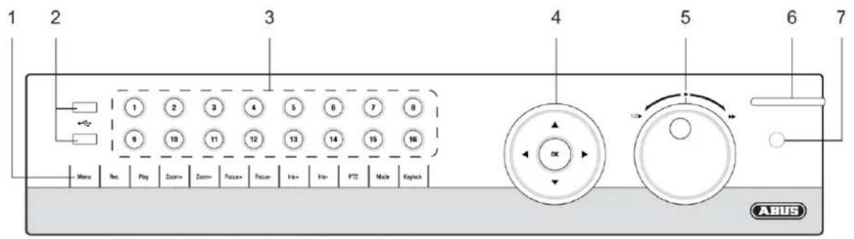
text_image
1 2 3 4 5 6 7 8 9 10 11 12 13 14 15 16 Menu Res Play Zoom+ Zoom- Focus+ Focus- Info+ Info- PTZ Mode Keyboard AX 10 6 7 ABUSRearside
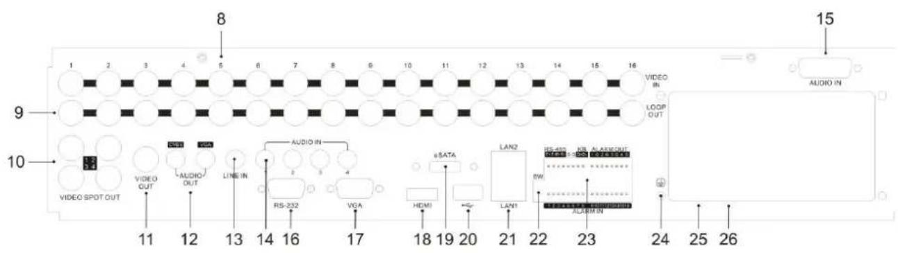
text_image
1 2 3 4 5 6 7 8 9 10 11 12 13 14 15 16 8 9 10 VIDEO OUT VIDEO OUT AUDIO OUT LINE IN AUDIO IN RS-232 VGA HDMI eSATA LAN2 IS-420 I/O ALARM IN LAN1 BIW ALARM IN 11 12 13 14 16 17 18 19 20 21 22 23 24 25 26 VIDEO IN LOOP OUT AUDIO INSystem operation
General information
The device can be controlled as follows:
- Using the operating elements on the front of the device
• Using the remote control
• Using the USB mouse
Operating elements on the device
i
Note
Pay attention to the overview on page 69.
| No. | NameFunction |
| 1 | Recorder operating keys:MENU:Calls up the main menuSwitches the key tones on and off (press and hold down for 5 seconds)REC:Calls up the menu for manual recordingPLAY:Opens the playback menuZOOM+:Zooms in on the image section in PTZ modeZOOM-:Zooms out of the image section in PTZ modeSwitches the video output in live mode: Monitor – Spot Monitor or Video Out – Video Spot OutFOCUS+:Sets the focus in PTZ modeFOCUS-:Sets the focus in PTZ modeIRIS+:Opens the irisIRIS-:Closes the iris in PTZ modePTZ:Activates the PTZ controlMODE:Switches the screen viewKEYLOCK:Locks the control keys |
| 2 | USB ports:For external USB 2.0 devices (e.g. mouse, external disk drive or DVR burner) |
| No. | NameFunction |
| 3 | Camera selection keys (1, 2, 3...):Displays the camera status:White: Camera is connectedBlue: Connected camera is recordingNot lit: No camera connectedIn the live view:Selects the camera and displays the full-screen view |
| 4 | Directional keypad:During playback:▲,▼ Sets the speed◀,▶ Previous / next dayIn the live view:Selects the channelIn menus:NavigationOK key:Press and hold for 5 seconds to switch the device on and offConfirms the selectionTicks / unticks the boxesDuring playback:PLAY/PAUSEIncreased/ decreased playback speed:Normal playback speed |
| 5 | Jog Shuttle:During playback:Outer ring (shuttle ring) change playback speedInner ring to play single frames in single mode In menus:Inner ring moves the cursor upwards / downwardsOuter ring moves the cursor left / rightIn the live view:Selects the channel |
| 6 | DVR status LED:Displays the device status:White (constantly lit): System status is OKWhite (flashing): System status is OK, recording settings are stored, surveillance mode is activeBlue (constantly lit): At least one camera is currently recordingRed (constantly lit): System maintenance required |
| 7 | IR receiver:For the remote control |
Connections on the rear of the device

Note
Pay attention to the overview on page 69.
| No. | NameFunction |
| 8 | Video IN: BNC video inputs for analog cameras (1–8 or 1–16 respectively) |
| 9 | Video LOOP OUT: looped video outputs |
| 10 | VIDEO SPOT OUT:video spot outputs, configured using the recorder menu |
| 11 | VIDEO OUT:BNC video output for connecting a monitor |
| 12 | AUDIO OUT:audio outputs (RCA) |
| 13 | LINE IN:audio input (line, RCA) |
| 14 | AUDIO IN (RCA):audio inputs 1–4 |
| 15 | AUDIO IN (DB26):TVVR60011: audio inputs 5–8TVVR60021: audio inputs 5–16 |
| 16 | RS-232 port:serial port – not functional |
| 17 | VGA port:VGA monitor port |
| 18 | HDMI port:HDMI monitor port |
| 19 | eSATA port:connection for an external hard drive |
| 20 | USB port:additional USB connection |
| 21 | LAN1 & LAN2:2 x RJ45 ports (for the network connection) |
| 22 | DIP switch:DIP switch for end-of-line resistor RS-485 connection |
| 23 | RS-485, ALARM IN, ALARM OUT:RS-485 port for PTZ cameras, max. 16 alarm in- |
| puts, max. 4 relay outputs | |
| 24 | Ground (GND):ground connection |
| 25 | Power supply:connection for cold device cable, 100–240 V AC, 50–60 Hz |
| 26 | Power ON/OFF:on and off device switch |
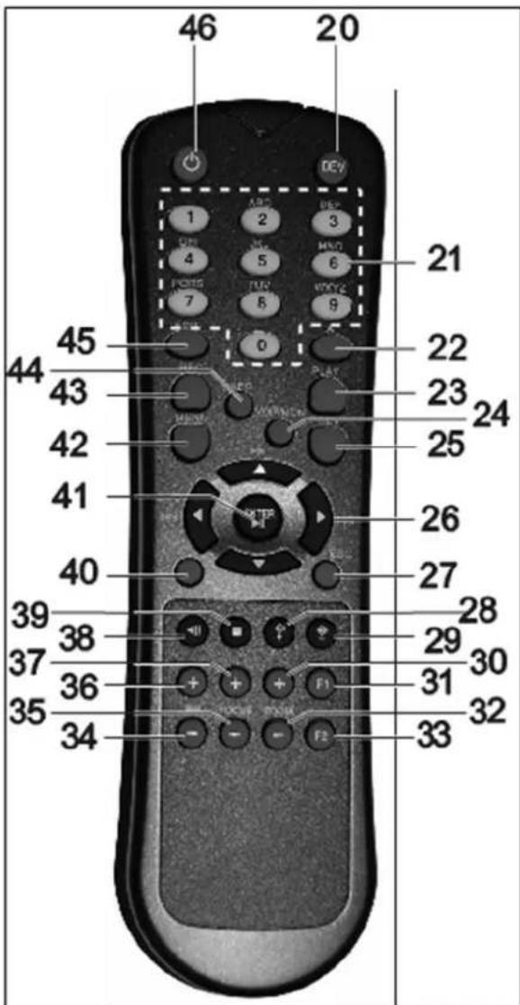
Remote control (TVAC40930)
text_image
46 20 1 ABC 2 3 4 5 6 7 8 9 21 45 22 44 43 23 42 24 41 25 40 26 27 39 38 28 37 36 29 30 35 36 31 32 34 33Operating elements on the remote control

Note
Pay attention to the remote control diagram on page 67.
| No. | NameFunction |
| 20 | DEV:Assigns the remote control with the device ID |
| 21 | Alphanumeric keys:Selects the camera (channel) in the live viewEntry of letters and digits in system fields |
| 22 | A:Changes the entry format (upper / lower case, symbols, digits) |
| 23 | PLAY:Starts playback |
| 24 | VOIP:Not used |
| 25 | PREV:Changes the screen display in the live view |
| 26 | Navigation keys:During playback:▲,▼ Sets the speed◀,▶ Previous / next dayIn the live view:Selects the camera (channel selection)In menus:Navigation |
| 27 | ESC:Not used |
| No. | NameFunction |
| 28 | Not used |
| 29 | Not used |
| 30 | Zoom +:Zooms in on the image section in PTZ mode |
| 31 | F1:In lists:• Selects all available options |
| 32 | Zoom -:Zooms out of the image section in PTZ mode |
| 33 | F2:Switches between tabs |
| 34 | IRIS-: In PTZ mode:• Closes the iris |
| 35 | Focus-: In PTZ mode:• Brings the image section into focus |
| 36 | IRIS+: In PTZ mode:• Opens the iris |
| 37 | Focus+: In PTZ mode:• Brings the image section into focus |
| 38 | ◀II: Pause / reverse playback |
| 39 | ■: Stops playback |
| 40 | PTZ:Switches on PTZ control |
| 41 | Enter ▶II:Confirms the selectionTicks / unticks the boxesDuring playback:PLAY/PAUSESingle play mode:Advances by a single frame |
| 42 | MENU:Calls up the main menuSwitches the key tones on and off (press and hold down for 5 seconds) |
| 43 | REC:Opens / starts manual recording |
| 44 | INFO:Switches to another monitor in the live view |
| 45 | EDIT:General use:Activates the text entry; backspace in text fields |
| 46 | ◀POWER:Switches on/off (hold down for 5 seconds) |
Mouse operation

Note
Further descriptions in these operating instructions are made with the mouse.
The device is suitable for use with a USB mouse. Connect the mouse to the USB port.
| Button | Function |
| Left | Single-click:Selection in menu, activation of an entry field or tabDouble-click:Switches between the screen display of single and multiple images in the live view and during playbackClick and drag:In PTZ mode: Camera controlSet-up of alarm areas or zones |
| Right | Single-click:Calls up the pop-up menu |
| Scroll wheel | In the live view:Shows previous / next cameraIn menus:Scrolls through the menus |
Device overview 69
System operation....70
General information 70
Operating elements on the device 70
Connections on the rear of the device 71
Operating elements on the remote control 73
Mouse operation....73
Quick guide....77
Before you start....77
Installing the HDD 77
Establishing the connections 77
Configuring the device 77
Important safety information....78
Explanation of symbols 78
Proper use 78
General information 78
Power supply 78
Overloading / overvoltage....79
Cables 79
Installation location / operating environment 79
Remote control....79
Care and maintenance....80
Accessories....80
Putting into operation....80
Children and the device 80
Introduction 81
General information 81
Unpacking the device....81
Scope of delivery 81
On-screen keyboard 82
Starting the device 82
Switching off, locking and rebooting the device....82
Status displays....83
General information 83
DVR status LED 83
Camera selection keys – status LED 83
Displays on the monitor 83
Setup wizard....84
Setting up the system 84
Setting up the administrator 84
Time / Date 84
Network Settings....85
HDD Management 85
Setting up network cameras 85
Camera recording 86
Live view 87
Overview 87
Status symbols 87
Pop-up menu for mouse operation ....87
Selection bar in the camera image 88
Settings 89
Setting the camera output 89
Playback....90
General information 90
Playback screen....90
Using the control panel....90
Right click when playback is running 91
Main menu 92
Menu overview....92
Menu description 92
Menu description 93
Settings....94
Overview....94
General....94
Terms and definitions ......95
Network layout....96
Network-configuration 96
Live view 103
Warning....103
User....103
Camera 105
OSD 105
Image 106
PTZ 106
Motion 106
Handling....106
Private zone 108
Tamper surveillance....108
Video signal loss....108
Setting up....109
Schedule....109
Encoding....110
Confirm the settings by clicking Apply and leave the menu with Back. 111
Advanced settings 111
Holidays....111
HDDs....112
Installing the HDD 112
HDD Management parameters 112
HDD settings of the cameras....113
Hard disc setting 113
Checking the HDD status....114
Setting up the HDD alarm 114
S.M.A.R.T....114
Continuous Recording 115
Event....115
Marking 115
Image 115
Maintenance 117
System Info 117
Log Search....117
Import / Export 118
Upgrade 118
Contents
Default....119
Network....119
Video Export....121
Duration....121
Event (event type ‘Alarm input’)....122
Event (event type 'Motion') 122
Manual Management....123
Record....123
Continuous Capture 123
Alarm....123
Shutdown....123
Troubleshooting....124
Device cleaning and care....124
Note....124
Technical data 125
Disposal 126
Information on the EU directive on waste electrical and electronic equipment 126
Information on handling batteries 126
Important information on disposing of batteries....126
Information on the European RoHS directive 126
Glossary....127
Overview of specialist terms 127
Internal HDD 129
Quick guide
Before you start
The following preparatory steps must be made:
- Pay attention to the general information, safety information and notes on setting up and connecting the device (see page 70).
- Check the contents of the package for completeness and damages.
- Insert the batteries into the remote control.

Note
Pay attention to the information in the separate quick guide.
Installing the HDD

Warning
Switch off the device and disconnect it from the mains power supply. Pay attention to the required earthing of the device to avoid static discharge.
- Install one or more HDDs (see the separate quick guide).
- Firstly, establish the connection to the motherboard using the red data cable (small connector).
- Connect the power supply cable (large 5-pin connector).
- Check that the connections are secure.
- Close the housing.

Note
Only use HDD's that are approved for video recording and 24/7 usage.
Establishing the connections

Note
Pay attention to the minimum radius when laying cables. Do not kink the cable.
- Connect all network cameras with your network
- Connect the audio connections.
- Connect the sensors to the alarm inputs.
- Connect the monitor to the HDMI/VGA or BNC connection.
- Connect the mouse to the USB port.
- Establish a connection to the mains power supply.
- Switch on the device using the POWER switch on the rear. The DVR status display on the front of the device lights up.
Configuring the device

Note
Pay attention to the information in the separate quick guide.
- Proceed through the individual steps in the setup wizard (see page 96).
- The following settings are configured in sequence:
• Language selection for the user interface - Administrator setup
- General settings (date, time etc.)
• HDD management (initialisation etc.) - Network settings
- Camera management

Note
Subsequent changes to the date and time can lead to the loss of data!

Note
Check the ABUS homepage (www.abus.com) if for this device any firmware updates are available and install these
Important safety information
Explanation of symbols
The following symbols are used in this manual and on the device:
Symbol


Signal word Meaning
| Warning | Indicates a risk of injury or health hazards. |
| Warning | Indicates a risk of injury or health hazards caused by electrical voltage. |
| Important | Indicates possible damage to the device/accessories. |
| Note | Indicates important information. |
The following labels are used in the text:
Meaning
| 1. ... | Set of tasks or instructions with a defined sequence in the text |
| 2. ... | |
| ... | Set of points or warnings without a defined sequence in the text |
| ... |
Proper use
Only use the device for the purpose which it was designed and built for. Any other use is considered inappropriate.
This device may only be used for the following purpose(s):
- This DVR recorder is used in combination with connected video signal sources (network cameras) and video output devices (CRT or TFT monitors) for object surveillance.

Note
Data storage is subject to national data-protection guidelines.
During installation, inform your customers regarding the existence of these guidelines.
General information
Before using the device for the first time, read the following instructions carefully and pay attention to all warnings, even if you are already familiar with electronic devices.

Warning
All guarantee claims become invalid for damages caused by non-compliance with these operating instructions.
We cannot be held liable for resulting damages.

Warning
We cannot be held liable in the event of material or personal damage caused by improper operation or non-compliance with the safety information.
All guarantee claims are invalid in such cases.
Keep this manual in a safe place for future reference.
If you pass on or sell the device, you must also include this user manual.
This device has been manufactured in accordance with international safety standards.
Power supply
- Only operate this device through a power source which supplies the mains power specified on the type plate.
- If you are unsure of the power supply at the installation location, contact your power supply company.

Warning
Avoid data loss!
Always use an uninterruptible power supply (UPS) with overvoltage protection.
- Disconnect the device from the mains power supply before carrying out maintenance or installation work.
- The on/off switch does not completely disconnect the device from the mains power supply.
- To disconnect the device completely from the mains power supply, the plug must be disconnected from the mains socket. Therefore, the device should be positioned so that direct and unobstructed access to the mains socket is guaranteed at all times and the plug can be disconnected immediately in an emergency.
To avoid the possibility of fires, the plug should always be disconnected from the network socket if the device is not used for long periods. Disconnect the device from the mains power supply before impending electrical storms, or use an uninterruptible power supply.

Warning
Never open the device on your own! There is a risk of electric shocks!
If it is necessary to open the device, consult trained personnel or your local maintenance specialist.
- The installation or modification of a HDD should only be made by trained personnel or your local maintenance specialist.

Warning
The installation of additional equipment or modification of the device invalidates your guarantee if not carried out by trained personnel.
We recommend having the HDD installed by a maintenance specialist.
Your guarantee is invalidated in the event of improper installation of the HDD.
Overloading / overvoltage
- Avoid overloading of mains sockets, extension cables and adapters as this can result in fires or electric shocks.
- Use overvoltage protection to prevent damages caused by overvoltage (e.g. electrical storms).
Cables
- Always hold cables by the connector, and do not pull the cable itself.
- Never touch the mains cable with wet hands, as this can lead to a short circuit or electric shock.
- Never position the device, furniture or other heavy items on the cable. Ensure that the cable does not become kinked, especially on the connector and sockets.
- Never knot the cable, and do not tie it to other cables.
- All cables should be laid so that they cannot be stepped on or cause an obstruction.
- A damaged mains cable can cause a fire or electric shock. Check the mains cable from time to time.
- Never modify or manipulate the mains cable or plug.
- Do not use plug adapters or extension cables that do not conform to the applicable safety standards, and do not make alterations to power supply cables or mains cables.
Installation location / operating environment
- Position the device on a firm, level surface and do not place any heavy objects on the device.
- The device is not designed for operation in rooms subject to high temperatures or moisture (e.g. bathrooms), or in excessively dusty rooms.
- Operating temperature and ambient humidity: -10 °C to 55 °C, maximum 85% relative humidity. The device may only be operated in moderate climate conditions.
Ensure the following:
- Sufficient ventilation must be present at all times (do not place the device in a storage rack, on thick carpets, on a bed or anywhere where the ventilation slots are covered. Make sure that a gap of at least 10 cm is present on all sides).
- The device must not be exposed to direct heat sources (e.g. heaters).
- The device must not be exposed to direct sunlight or strong artificial light.
- The device must not be placed in close proximity to magnetic fields (e.g. loudspeakers).
- Naked flames (e.g. candles) must not be placed on or near the device.
- Contact with spraying or dripping water and aggressive liquids must be avoided.
- The device must not be operated in close proximity to water, and must not be submerged under any circumstances (do not place objects containing water on or near the device, such as vases or drinks).
- Foreign objects must not penetrate the device.
- The device must not be exposed to strong variations in temperature, as this can lead to condensation and electrical short circuits.
- The device must not be exposed to excessive jolts or vibrations.
Remote control
- Remove all batteries if the device will not be used for a sustained period, as these can leak and damage the device.
Care and maintenance
Maintenance is necessary if the device has been damaged. This includes damage to the plug, mains cable and housing, penetration of the interior by liquids or foreign objects, exposure to rain or moisture or when the device does not work properly or has fallen.
- Disconnect the device from the mains power supply before maintenance (e.g. cleaning).
- If smoke develops or unusual noises or odours are detected, then switch off the device immediately and pull the mains plug from the socket. In such cases, the device should not be used until it has been inspected by a qualified technician.
- Maintenance work should only be carried out by qualified specialists.
- Never open the housing on the device or accessories. There is a risk of fatal injury due to an electric shock when the housing is opened.
- Clean the device housing and remote control with a damp cloth.
- Do not use solvents, white spirit or thinners as these can damage the surface of the device.
- Do not use any of the following substances:
- Salt water, insecticides, solvents containing chlorine or acids (ammonium chloride) or scouring powder.
- Gently rub the surface with a cotton cloth until it is completely dry.

Warning
The device works under dangerous voltages. The device must only be opened by authorised specialists. All maintenance and service work must be carried out by authorised firms. Improper repairs can expose device users to the risk of fatal injury.
Accessories
- Only connect devices that are suitable for the intended purpose. Otherwise, hazardous situations or damage to the device can occur.
Putting into operation
- Observe all safety and operating instructions before putting the device into operation for the first time.
- Only open the housing to install the HDD.

Warning
When installing the device in an existing video surveillance system, ensure that all devices are disconnected from the mains power supply and low-voltage circuit.

Warning
If in doubt, have a specialist technician carry out assembly, installation and connection of the device.
Improper or unprofessional work on the mains power supply or domestic installation puts both you and other persons at risk.
Connect the installations so that the mains power circuit and low-voltage circuit always run separately from each other. They should not be connected at any point or become connected as a result of a malfunction.
Children and the device
- Do not allow children access to electrical devices. Never allow children to use electrical devices without supervision. Children may not be able to accurately detect possible risks. Small parts can be life-threatening if swallowed.
- Keep batteries away from small children. Call for medical assistance immediately if a battery is swallowed.
- Keep packaging materials away from children (danger of suffocation).
- This device should not be used by children. If used improperly, spring-loaded parts can be ejected and cause injuries to children (e.g. eye injuries).
Introduction
Dear customers,
Thank you for purchasing this product.
This product complies with current domestic and European regulations. Conformity has been proven, and all related certifications are available from the manufacturer.
To maintain this status and to guarantee safe operation, it is your obligation to observe these operating instructions!
Read the entire operating manual carefully before putting the product into operation and pay attention to all operating and safety information!
All company names and product descriptions are trademarks of the corresponding owner. All rights reserved.
In the event of questions, please contact your local maintenance specialist or dealer.

Disclaimer
These operating instructions have been produced with the greatest care. Should you discover any missing information or inaccuracies, please contact us under the address shown on the back of the manual. ABUS Security-Center GmbH does not accept any liability for technical and typographical errors, and reserves the right to make changes to the product and operating instructions at any time and without prior warning. ABUS Security-Center GmbH is not liable or responsible for direct or indirect damages resulting from the equipment, performance and use of this product. No forms of guarantee are accepted for the contents of this document.
General information
In order to use the device correctly, read this user manual carefully and keep it in a safe place for later use.
This manual contains instructions on recorder operation and maintenance. Consult an authorised specialist if the device needs to be repaired.
Unpacking the device
Handle the device with extreme care when unpacking it.
The packaging is made of reusable materials, and should always be passed on for recycling.
We recommend the following:
Paper, plastic packaging, cardboard and corrugated cardboard should be disposed of in the appropriate recycling containers.
If recycling containers are not available in your local area, then you can dispose of these materials as domestic waste.
If the original packaging has been damaged, inspect the device. If the device shows signs of damage, then return it in the original packaging and contact the manufacturer.
Scope of delivery
• ABUS 16/32 channel hybrid DVR
- Mains cable
- SATA cable and screws for HDD
- Bracket and screws for server racks
- Software CD
- User manual (On CD or enclosed)
- Quickguide (On CD or enclosed)
- Terminal connectors
On-screen keyboard
The on-screen keyboard appears after clicking on a text entry field with the mouse:

text_image
1 2 3 4 5 6 7 8 9 0 Q W E R T Y U I O P A S D F G H J K L Z X C V B N M a Space Enter ESCThe following screen keyboard appears during mere numerical entry:

text_image
1 2 3 4 5 6 7 8 9 . 0 Space Enter ESCThe keys have the same function as on a computer keyboard.
• To enter the character, left-click the mouse.
• To finish data entry, press Enter.
- To delete the character in front of the cursor, click on
- To switch between upper and lower case, click on the framed a symbol. The current setting is displayed above the keyboard.
- To cancel the entry or exit the field, press ESC.
Starting the device

Important
The device must only be operated with the mains power specified on the type plate.
For safety reasons, use an uninterruptible power supply (UPS).
After the device has been connected to the power supply and the main switch on the rear of the device is switched on, the DVR status LED lights up.
- The device carries out a self-test during the start-up procedure.
- The setup wizard appears. Exit the wizard to access the live view.
Switching off, locking and rebooting the device
Click on "Shutdown" in the main menu. The overview appears.
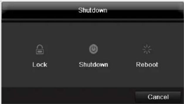
text_image
Shutdown Lock Shutdown Reboot Cancel- To switch off the device, select ShutDown and confirm by pressing Yes. The device is then switched off.
- Do not press any keys during the shutdown procedure.
- To lock the system, select the corresponding Lock symbol on the left. The user interface is now locked and a password must be entered to access the menu.
- To reboot the device, select the corresponding Re-boot symbol on the right. The device is then rebooted.
Switching on the device
- Press and hold the OK key for 5 seconds to switch the device back on.
Status displays
General information
The following status displays indicate the current operating state:
• LEDs on the front of the device
- Acoustic signal tones
- Icons (display elements) on the monitor

Note
Pay attention to the information in the separate quick guide.
DVR status LED
| State | Function |
| White (constantly lit): | System status is OK |
| White (flashing): | System status is OK, recording settings are stored, surveillance mode is active |
| Blue (constantly lit): | At least one camera is currently recording |
| Red (constantly lit): | System maintenance required |
Camera selection keys – status LED
| State | Function |
| Off: | No camera connected |
| White (constantly lit): | Camera is connected |
| Blue (constantly lit): | Camera is currently recording |
Displays on the monitor
The device shows the date and time, camera name and whether a recording is in progress.
• Continuous recording: Blue "R"
- Alarm recording: Red "R"
- Motion recording: Yellow "R"
Setup wizard
Setting up the system
The setup wizard guides you through the necessary basic system settings. The DVR is then set up for recording and surveillance.

Note
All detailed settings can be found in the device menu (see overview on 92).
The language selection appears after switching on for the first time:
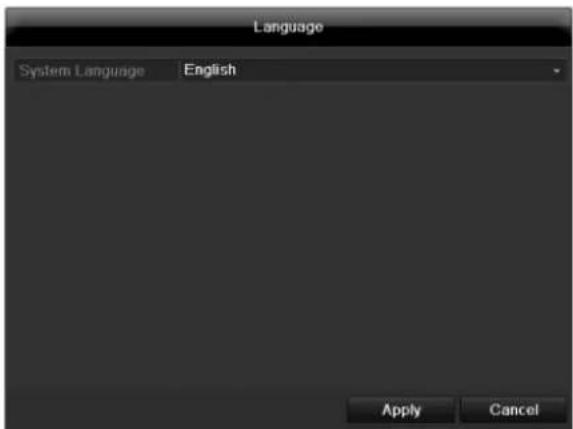
text_image
Language System Language English Apply Cancel- Click the entry field and select the desired language from the list. Click on Apply to continue. The following query appears:
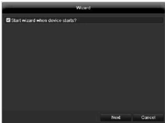
text_image
Wizard ✓ Start wizard when device starts? Next Cancel- Click on Next to start the wizard.

Note
After the system is set up, you can untick the box. The setup wizard is then no longer started automatically.
Setting up the administrator

Warning
Note down the admin password.
The following password is preset
"1 2 3 4 5"
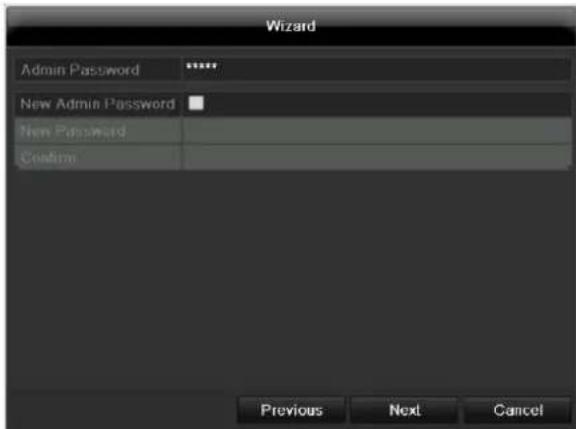
text_image
Wizard Admin Password ****** New Admin Password * New Password Confirm Previous Next Cancel- Click the entry field and enter your admin password.
- To assign a new password, tick the box next to New Admin Password.
- Enter the new password and confirm in the field below.
- Click on Next.
Time / Date
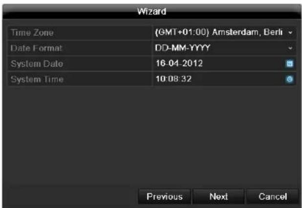
text_image
Wizard Time Zone (GMT+01:00) Amsterdam, Berli Date Format DD-MM-YYYY System Date 16-04-2012 System Time 10:08:32 Previous Next CancelEnter the system time (date and time). Click on Next to accept the data.
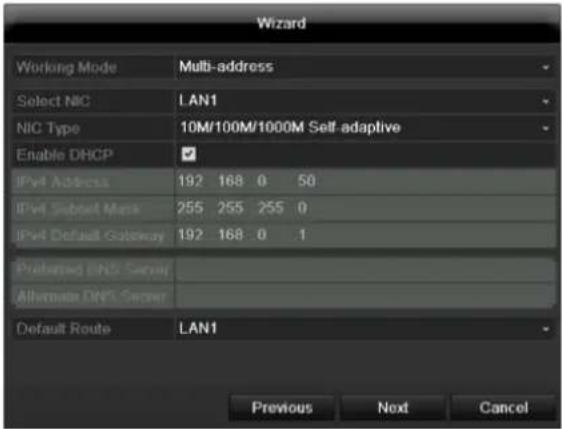
Network Settings
text_image
Wizard Working Mode Multi-address Select NIC LAN1 NIC Type 10M/100M/1000M Self-adaptive Enable DHCP ✓ IPvI Address 192 168 0 50 IPvI Subunit Mask 255 255 255 0 IPvI Default Gateway 192 168 0 .1 Preferred DNS Server Alternate DNS Server Default Route LAN1 Previous Next Canceli
Note
To check whether DHCP can be selected (or if you have to set the IP address and other settings manually), consult your network administrator.
- DHCP activated: If DHCP is set up in the network router, then tick the DHCP box. All network settings are then made automatically.
- DHCP not activated: Enter the data manually (IPv4 address, IPv4 subnet mask and IPv4default gateway = IPv4 address of the router). You can also optionally enter the address of the DNS server that you need for sending the E-mail.
A typical address specification is as follows:
• IPv4 address: 192.168.0.50
• IPv4 Subnet mask: 255.255.255.0
• IPv4 Default gateway: 192.168.0.1
• Preferred DNS server: 192.168.0.1
i
Note
When the device is accessed remotely via the internet, it should be given a fixed network address.
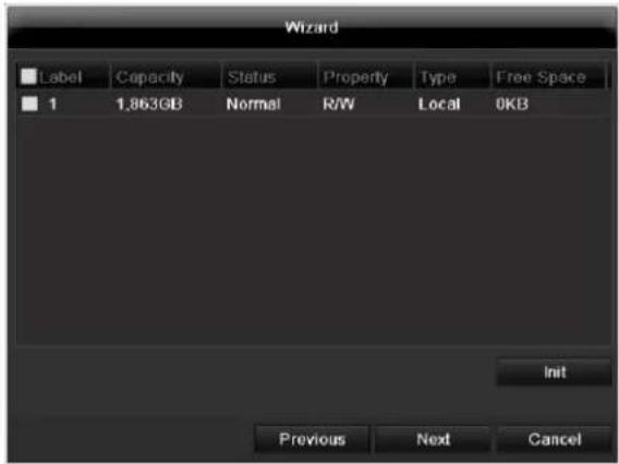
HDD Management
text_image
Wizard Label Capacity Status Property Way Type Free Space 1 1,863GB Normal R/WLocal 0KB Init Previous Next Cancel- To set up a new hard disc, activate the "Check box" with a left click and then click on Init.

Warning
All data on the drive is deleted!
- Confirm the prompt by pressing OK. The HDD is then set up for operation. The progress is displayed on the status bar.
- Exit the setting by pressing Next.
Setting up network cameras
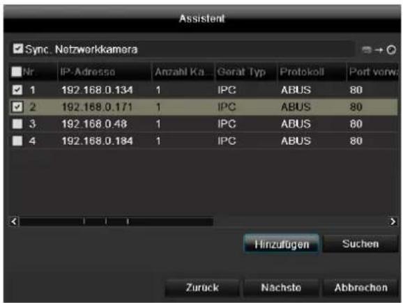
- To setup network cameras, click on Search.
- You can find an overview of all the network cameras found below.
- Activate the "Checkbox" with a left-click to select the network camera and then click on Add.
- Click on Next
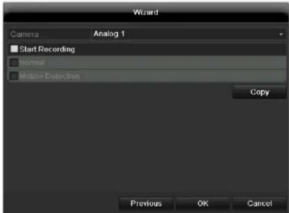
Camera recording
text_image
Wizard Camera Analog 1 Start Recording Normal Motion Detection Copy Previous OK Cancel- At "Camera" select a camera with which you would like to record.
- Activate the check box "Start recording".
- Select the type of recording. You can choose between "Time plan" and "Motion recognition". Arm the motion detection inside the camera for recording motion.
- Press Copy to take on the setting for other cameras. For this, select the cameras that appear in the new window. Activate the respective check box with a mouse click.
- Finalize the setting and end the installation assistant with OK.
Live view
Overview
The live view starts automatically after the device is switched on.
You can also go back to the live view by pressing the Menu key repeatedly.
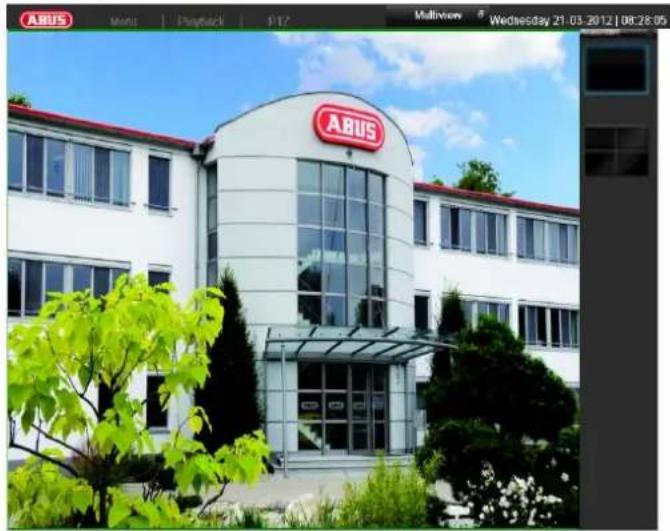
natural_image
Exterior view of a modern white building with a red logo on the facade, surrounded by greenery and trees (no readable text or symbols)The following menus are found in the screen header:
- Menu
- Playback
• PTZ
The view pop-up menu is found on the right. The time and date are displayed on the right.
- To open the view pop-up menu, click on the rectangular symbol at the top-right of the menu bar.
- Click on one of the symbols to switch between the different views.


The signals of the connected cameras are displayed on the main screen.
- By double-clicking the left mouse key, you can display the camera image as a full-screen view or switch back to the original view.
Status symbols
- The following symbols are displayed depending on the operating status of the device:
| Symbol | Meaning |
| R | Red: Event RecordingEvent recording |
| R | Yellow: Motion RecordingRecording at motion detection |
| R | Blue: RecordingContinuous recording |
Pop-up menu for mouse operation

Note
Press the right mouse button when the cursor is positioned on a live image.
The following settings can be made. The arrow pointing to the right indicates that a sub-menu is opened for selection:
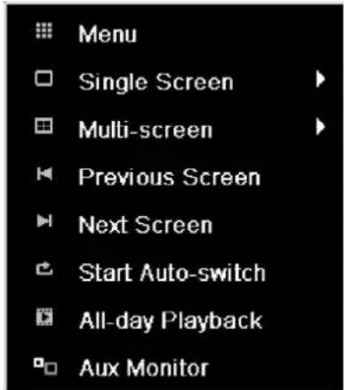
text_image
Menu Single Screen Multi-screen Previous Screen Next Screen Start Auto-switch All-day Playback Aux Monitor| Menu | Opens the main menu |
| Single Screen | Full-screen view for selected camera |
| Multi Screen | Various camera layouts |
| Previous Screen | Changing the presentation of the previous camera |
| Next Screen | Displays the next camera(s) |
| Start Auto-Switch | Starts the camera sequence |
| All-day Playback | Switches to playback mode |
| Output mode | Renders the image softer or sharper |
| Aux Monitor | to spot monitor |
| i | NoteStop Auto-switch:Specify the delay in the image sequence in the display settings. |
| i | NoteActivation of “AUX monitor” without a connected spot monitor:Mouse pointer function is deactivated. |
Selection bar in the camera image
Click on the camera image in single or multi view. A selection bar appears:

natural_image
Toolbar with eight application icons including zoom, document, and search (no text or labels visible)| No | Meaning of symbol |
| (1) | Area to move the miniature bar |
| (2) | Activate / deactivate manual recording |
| (3) | Immediate playback of the last 5 minutes |
| (4) | Activate / deactivate audio output of video output |
| (5) | Immediate image of selected channel |
| (6) | PTZ-control |
| (7) | digital zoom |
| (8) | Leaving the selection bar |
Settings

Note
The live view can be set as follows.
Open the main menu, then click on "Configuration". Then click on "Liveview":
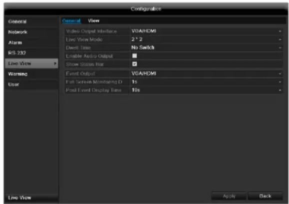
text_image
Configuration General View Network Video Output Interface VGA/HDMI Alarm Live View Mode 2*2 Dwell Time No Switch RS 232 Enable Audio Output Show Status Bar Warning Event Output VGA/HDMI User Full Screen Monitoring D 1s Post Event Display Time 10s Live View Apply BackThe following settings are available in the TAB "General":
| Video Output Interface | VGA/HDMI, Main CVBS, Spot monitorSelect the connection where the settings are changed |
| Live View Mode | Different camera layouts |
| Dwell Time | Switching time between the individual cameras and the sequence display |
| Enable Audio Output | Activate/deactivate audio output of the video output The audio signal is only given if the corresponding camera input is presented as a full screen. |
| Event Output | Allocate monitor for the output of events |
| Full Screen Monitoring Duration | in seconds, where the event on the allocated monitor will be displayed. |
| Post Event Display Time | in seconds, the duration of the Pop-up window when an event occurs. |

Note
The recorder image can either be shown on an HDMI or a VGA monitor. The combination of HDMI and VGA output is supported.
The BNC output can be used either for a spot monitor or a separate monitor.

Note
VGA monitor connected:
A connected HDMI/VGA monitor automatically becomes the main monitor where the audio output is also assigned. The BNC output Video Spot Out output displays the cameras in sequence and in full screen.
If during the boot process of the DVR the HDMI/ VGA cable is not connected, the main video signal is displayed at BNC output MAIN. Connect the HDMI/VGA cable and reboot the DVR in order to display the main video signal at the VGA output.
No HDMI/VGA monitor connected:
The main video signal is displayed at BNC output MAIN. The BNC output Video Spot Out output displays the cameras in sequence and in full screen.
Setting the camera output
You can have a maximum of 8 or 16 cameras respectively (TVVR60011/TVVR60021) displayed in the live cast at the same time.
- Click on the TAB "View".
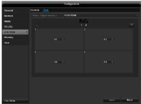
text_image
Configuration General View Video Output Interface VGA/HDMI General Network Alarm RS-232 Live View Warning User Live View Apply Back-
Select the display mode.
-
1 x 1
- 2 × 2
- 3 × 3
• 1 + 5
• 1 + 7 -
4 × 4
-
The camera signal is assigned to the corresponding image section using the navigation keys.
- "X" means that this camera is not displayed.
- Click on Apply to accept the settings.
Playback
General information
Playback can be made in three different ways:
• Through the video search in the main menu
- From the live view
• Through the log file in the maintenance menu
i
Note
The buttons "previous file/day/event" are used differently depending on the playback mode:
Normal playback:
By pressing the button the playback jumps to the previous/next day.
Video Search:
By pressing the button the playback jumps to the previous/next event day.
Video Export:
By pressing the button the playback jumps to the previous/next file.
i
Note
It is possible to start a simultaneous playback with up to 4/8 cameras.
Playback screen
Playback is controlled on the control panel:
text_image
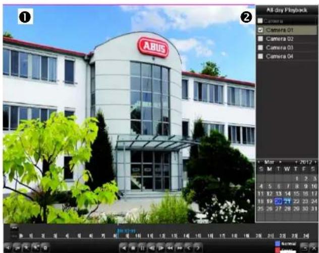
① ② All-day Playback Camera Camera 01 Camera 02 Camera 03 Camera 04 ① ② Mnr • + 2012 + S M T W T F S 1 2 3 4 5 6 7 8 9 10 11 12 13 14 15 16 17 18 19 20 21 22 23 24 25 26 27 28 29 30 31 Normal 5.7x3
| No. | Area |
| 1 | Running playback with date and time |
| 2 | Used to select the camera for feedback |
| 3 | Calendar with recording type |
| 4 | Control panel with time bar (see right) |
Using the control panel
The control panel (4) is used for controlling the running playback. The symbols have the following meaning:
(1)

text_image
00:00:11 0 1 2 3 4 5 6 7(2) (3) (4) (5) (6)

text_image
0| 9| 10| 11| 12| 13| 14| 15| 16| (16)(7) (8) (9) (10)(11)(12)(13)(14)(15)

text_image
17 18 19 20 21 22 23 24 Normal Event(17) (18) (19)
| No. | Meaning / function |
| 1 | Zoom in / Zoom out the time line (24/12/1 hours) |
| 2 | Audio playback switch on/ off |
| 3 | Define start point / end point of a video for securing data |
| 4 | Add marking |
| 5 | Add user-defined marking |
| 6 | Administer marking |
| 7 | Activates the digital zoom. One section of the overview area can be marked for enlargement. |
| 8 | Smart search (section search): Mark a section in the video image being played back which should be checked for motion (alternatively, click on full screen detection). The results will be displayed in the time scale, and are marked in green. |
| 9 | Backwards playback |
| 10 | Stop |
| 11 | Playback start / pause |
| 12 | Jump backward 30 seconds |
| 13 | Jump forward 30 seconds |
| 14 | Slow forward (slow motion) (1/16x - 1x) |
| 15 | Fast forward (1x - 16x) |
| 16 | Previous recording, previous day |
| 17 | Next file/day/event |
| 18 | Time bar:Click on the time bar with the mouse to continue playback from another pointTo start playback from a specific time, click onthe slider and drag it to the required time |
| 19 | Recording typeBlue = Continuous recordingRed = Event recording |
| 20 | Hides the control panel |
| 21 | Exits playback |

Note
You can zoom in on the screen image.
• Right-click in the running playback.
- Please choose 'Digital Zoom'.
- The zoom mode is active. Shift the zoom area by means of the window in the miniature screen.
• Right-click the image to finish.
Please klick on, Tag management' (6):
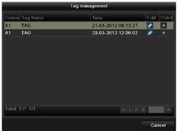
text_image
Tag management Gamer Tag Name Time Edit Delete A1 TAG 21-03-2012 08:13:27 A1 TAG 20-03-2012 12:00:02 Total: 2 P. 1/1 Cancel| Control Panel | Fades in/out the control field for playback control |
| Exit | Ends playback |
- In order to change the description of your marking, click on the process symbol. To remove, click on the delete symbol.
Right click when playback is running
Perform a right click on the playback image. The following options are available:
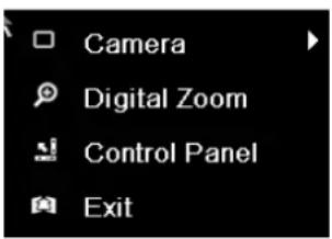
text_image
Camera Digital Zoom Control Panel Exit| Camera | Camera to be set |
| Digital Zoom | Enlarges the selected screen section digitally |
Main menu
Menu overview
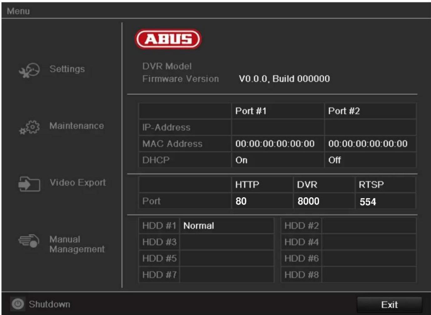
The following overview shows the main menus used to set and control the device.
Furthermore you can find important information regarding the device on the right side of the menu.
- Click on the menu to open it.
- Click Exit to close the menu overview.
text_image
Menu Settings Maintenance Video Export Manual Management ABUS DVR Model Firmware Version V0.0.0, Build 000000 Port #1 Port #2 IP-Address MAC Address 00:00:00:00:00:00 00:00:00:00:00:00 DHCP On Off HTTP DVR RTSP Port 80 8000 554 HDD #1 Normal HDD #2 HDD #3 HDD #4 HDD #5 HDD #6 HDD #7 HDD #8 Shutdown ExitMenu description
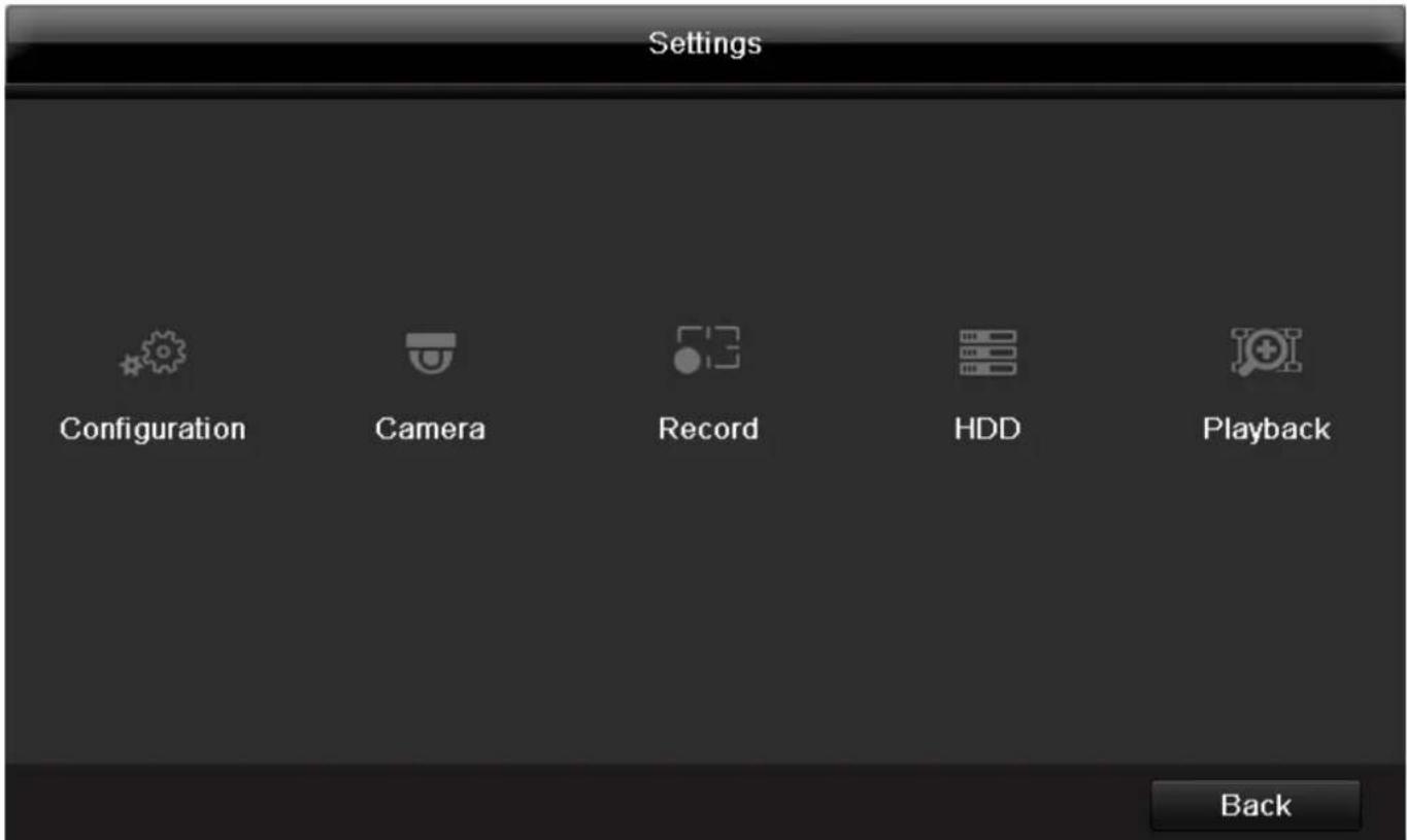
| Menü | Beschreibung | siehe S. |
| Settings | Includes the menusConfiguration, Camera, Record, HDD, Playback. | 90 |
| Playback | Parameter-controlled search for video and image recordings which were triggered by events such as alarms or motion detection, as well as alarm events and markings set in playback. | 117 |
| Video Export | Feature for exporting saved recordings onto USB media. | 121 |
| Manual Management | Starts or ends the manual video and image recording of selected cameras, as well as the manual switching of alarm outputs. | 123 |
| Shutdown | Lock, shutdown or restart the device. | 123 |
text_image
Settings Configuration Camera Record HDD Playback BackMenu description
| Menu | description | page |
| Configuration | Used for managing all device settings (General, Camera, Record, Network, Alarm, PTZ, RS232, Display, Exception, User). | 94 |
| Camera | Menu for setting camera parameters (OSD configuration, image mode, PTZ configuration, motion recognition etc.) | 129 |
| Record | Menu to set recording parameters (time plan, camera resolution, camera stream etc.). | 109 |
| HDD | Used for initialising or managing installed HDDs (assigning read/write functions, cameras, network HDD management etc.). | 112 |
| Playback | Parameter-controlled search for video or image recordings which were started by events like alarms or motion recognition, as well as alarm events and markings set in playback. | 115 |
Settings
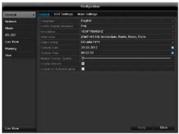
Configuration
text_image
Configuration General Network Alarm RS 232 Live View Warning User DST Settings More Settings Language English CCTS Output Standard PAL Resolution 1034*768/6GHz Time Zone (GMT+61.00) Amsterdam, Berlin, Rome, Paris Data Format DD-MM-YYYY System Data 21.03.2012 System Time 09:52:52 Mouse Packet Speed Enable Version Create ID Authentication Live View Apply Back
Note
The "Configuration" menu is used to manage all device settings.

Warning
Ensure that the date and time are set correctly. IMPORTANT:
Subsequent changes to the settings can lead to data loss!
Ensure a data backup has been made in good time beforehand.
Overview
| Menu | Setting | Page |
| General | Language, video, time, date, mouse pointer, password, time zones and other settings | 94 |
| Network | Required network settings (manual IP, DHCP, PPPOE, DDNS etc.) | 96 |
| Alarm | Assignment and parameterisation of detectors to alarm inputs and relay outputs | 125 |
| RS-232 | Parameters on the serial connection | 103 |
| Live View | Display settings and assignment of the event output | 103 |
| Warning | Behaviour of the device in exceptional cases (HDD full, network disconnected etc.) | 103 |
| User | Adding and changing users,assigning authorisation rights | 103 |

Note
Pay attention to the instructions in the corresponding sections.
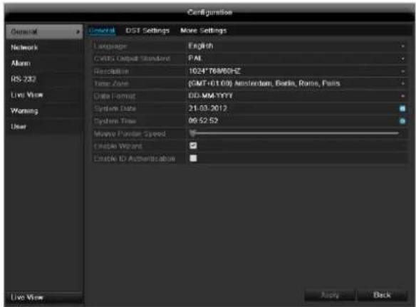
General
text_image
Configuration General DST Settings Move Settings Language English CVRG Output Standard PAL Resolution 1024*76M05HZ Time Zone (GMT+01/09) Amsterdam, Basta, Rome, Falls Data Format DD-MATYYY System Date 21.03.2012 System Time 09:52:52 Mouse Pattern Speed Open Wizard Enable ID Authentication Live View Apply Back| “General” tab | Setting |
| Language | Language on the OSD |
| CVBS Output Standard | PAL / NTSC |
| Resolution | Resolution on the monitor |
| Time Zone | GMT (Greenwich Mean Time) |
| Date Format | MM-DD-YYYY, DD-MM-YYYY, YYYY-MM-DD |
| System Date/Time | Date and time |
| Mouse Pointer Speed | Set on the scroll bar (left = low speed; right = high speed) |
| Enable Wizard | Box not ticked:Wizard will not appear after restart of the device.Box ticked:Wizard will appear after restart of the device. |
| Enable ID Authentication | Box not ticked:In order to enter a menu no password has to be entered. At access by network the password has to be entered.Box ticked:Password must be entered in order to use the menu. |
| TAB “DST settings” | Setting |
| Auto DST Adjustment | With an activated check box, the device converts automatically to summer time. |
| Enable DST | With an activated check box, an exact start / end date can be selected |
| From / To | Date of DST start / end |
| DST Bias | Daylight Saving Time Bias: Correction of the DST to the reference time |
| TAB “More Settings” | Setting |
| Device Name | Unique specification of the device |
| Device Number | Used for unique identification when using remote control |
| Output Mode | Makes the image softer or sharper. |
| CVBS Output Brightness | Scroll bar (left = darker; right = brighter) |
| Operation Timeout | Never / 1 to 30 minutes – regulates how long the menu is shown |
| Menu Output Mode | Defines the video outputs on which the OSD menu is visible. Options: Auto, HDMI/VGA, CVBS |
| Event Hint | Activates the event display in the live image (exclamation mark in the live image) |
Confirm the settings by clicking Apply and leave the menu with OK.
Network configuration
Correct network settings are essential in the following cases:
- When using remote control of the device and surveillance over your server
i Note Please read the following basic instructions before setting up the device.
A network is a connection of at least two network-capable devices.
Transmission types:
• Wired networks (e.g. CAT5 cable)
• Wireless networks (WLAN)
• Other transmission types (Powerline)
All systems have certain similarities, but can also differ in many ways.
Terms and definitions
An overview of relevant terms when using the device in a network can be found below.
| Parameter | Setting |
| IP address | An IP address is the unique address of a network device within a network.This address may only appear once within a network. Certain IP address ranges are reserved for public networks (e.g. the Internet). |
| Private address range | e.g. 10.0.0.0 – 10.255.255.255Subnet mask: 255.0.0.0172.16.0.0 - 172.31.255.255Subnet mask: 255.255.0.0192.168.0.0 - 192.168.255.255Subnet mask: 255.255.255.0 |
| Subnet mask | A subnet mask is a bit mask used for making decisions and assignments during routing.255.255.255.0 is the standard subnet mask in home networks. |
| Gateway | A gateway is a network device which allows all other network devices to access the Internet.This can be the computer connected to the DSL modem or – usually – the router or access point within the network. |
| Parameter | Setting |
| Name server | The name server is responsible for assigning a unique IP address to a web address or URL (e.g. www.google.de). Also known as DNS (Domain Name Server).When a domain name is entered into a browser, the DNS searches for the corresponding IP address of the server and forwards the query on.The IP of the provider's DNS can be entered here. However, it is often sufficient to select the IP of the gateway. This then forwards the queries independently to the provider DNS. |
| DHCP | The DHCP server automatically assigns the IP address, subnet mask, gateway and name server to a network device.DHCPs are available in current routers. The DHCP service must be specially set and activated (see the corresponding manual for more information).Note:When using fixed IP addresses and a DHCP server, make sure that the fixed IP addresses are outside the address range assigned by DHCP. Otherwise, problems could occur. |
| Port | A port is an interface used for communication by different programs. Certain ports are fixed (23: Telnet, 21: FTP), whilst others can be freely selected. Ports are important for different applications (e.g. external access to the device over a browser). |
| MAC address | The MAC address (Media Access Control or Ethernet ID) is the specific hardware address of the network adapter. This is used for the unique identification of the device in a computer network. |
Network layout
The device must be physically connected to the network over a CAT5 cable (see the connections on page 71).

Note
Pay attention to the specific information and instructions on the network devices.
Several switches, routers and access points can be connected to each other. Firewalls and other security software can affect the network.

Warning
When using a router, the network clients (e.g. the recorder) can be connected to the Internet and vice versa.
Make sure to use protective measures to prevent unauthorised external access (e.g. firewall, changing passwords, changing ports)!
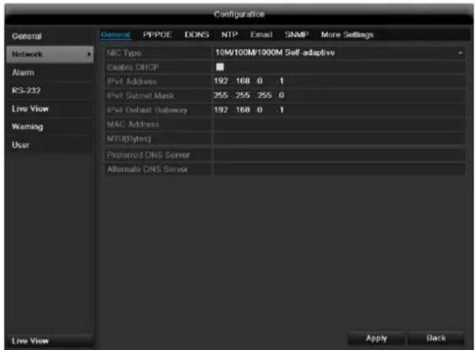
Network-configuration
text_image
Configuration General General PPPOE DONS NTP Email SNMP More Settings Network Alarm RS-232 Live View Warning User MAC Type 10W/100M/1000M Self-adaptive Enable DHCP IPv1 Address 192 168 0 .1 IPv1 Subnet Mask 255 255 255 0 IPv1 Default Gateway 192 168 0 .1 MAC Address MTU(Bytes) Preferred DNS Server Alternate DNS Server Apply Back| TAB | Settings |
| General | Settings for the local net and selecting the network mode. |
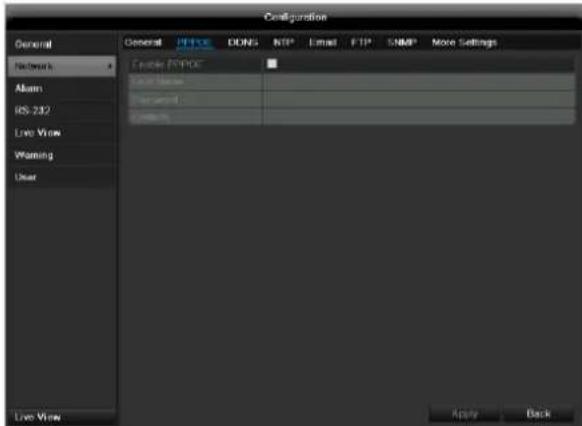
| PPPOE | PPPOE is used on ADSL connections and when using modems in Germany.Click on “Set” to enter the access data (ID and password) for your provider. |
| DDNS | Server for Dynamic Domain Name System management. Used for updating host names or DNS entries |
| NTP | Network Time ProtocolServer for time synchronisation |
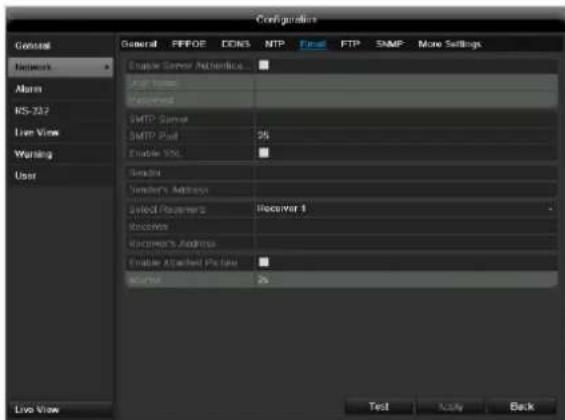
| Used to specify the e-mail settings which are sent as an e-mail to a specific address in the event of an alarm. | |
| FTP | Configure the address of an FTP server and the path for saving the files. |
| SNMP | Configure the parameters to receive information about the device status. |
| More Settings | Communication and HTTP port. |
TAB General
| Parameter | Setting |
| Working Mode | Net fault tolerance: Both network adapters (NIC) use the same network settings. The 2nd network adapter remains, in the event of problems with the 1st network adapter, available.Load balance: Both network adapters (NIC) use the same network settings. The bandwidth is split between the two adapters.Multi-address (standard): The network adapters (NIC) use different network settings. One adapter is defined as the standard adapter for external communication. The 2nd adapter is used for connecting IP cameras. |
| Select NIC | Choose between LAN1 and LAN2 for editing. |
| NIC Typ | Set the transmission speed of the installed network card here.Tip: 10M/100/1000M self adaptive |
| Enable DHCP | Tick the box if the IP addresses are assigned dynamically via DHCP in the network.DHCP activated: Subsequent entry fields are inactive (parameters assigned via DHCP).Note:If the IP addresses are assigned manually, ensure that DHCP is not active (box not ticked). |
| IPv4 Adress | Address of the network device in the network (manual assignment) |
| IPv4 Subnet Mask | Usually 255.255.255.0 |
| IPv4 Default Gateway | Address of the gateway for Internet access |
| IPv6 Adress 1 | Currently no functioning |
| IPv6 Adress 2 | Currently no functioning |
| IPv6 Standard Gateway | Currently no functioning |
| MAC Adress | Hardware address of the installed network card |
| MTU (Bytes) | Describes the max. size of the largest protocol data . |
| Preferred DNS Server | Address of the Domain Name Server (usually the IP address of the gateway) |
| Alternate DNS | IP address of the alternative DNS server |
| Default Route | Selection of the Ethernet connection for the external network connection |
(e.g. Internet).

Note
In certain modes some of these settings cannot be selected.
PPPOE
text_image
Configuration General Network: Alarm IRS-232 Line View Warning User Enable ENPOC Local Name: Parameters: Systems Live View Apply Back-
Tick the PPPOE box, enter the user name (Internet access ID) and password, then confirm the password.
-
Confirm the settings by pressing Apply.

Warning
Use PPPOE only if there is no router available.
DDNS
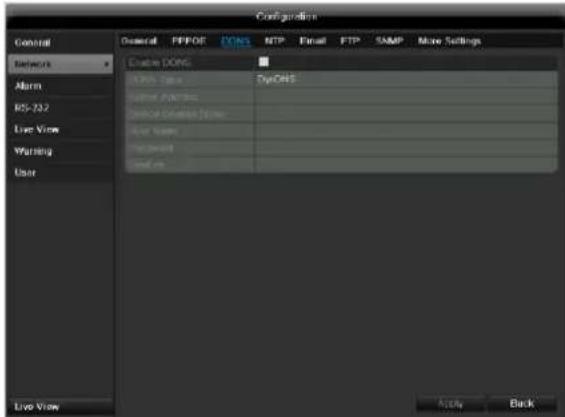
text_image
Configuration General PFPOF DONG RTP Email FTP SAMP More Settings Network Open TypeOne Open Type TypeOne Open Connection Open User Open User Live View Apply Back-
To use the ABUS DDNS function, you must first set up an account under www.abus-server.com. Please note the FAQs on the website when doing this.
-
Tick the "Enable DDNS" box, enter 'ABUS DDNS' as the "DDNS Type", then enter www.abus-server.com or "62.153.88.107" under "Server Address".
-
Confirm the settings by pressing Apply. The IP address of your Internet connection is now updated on the server every minute.
NTP
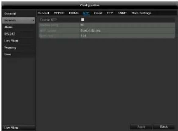
text_image
Configuration General PPPOE DONS FTP Email FTP SNMP More Settings Networks Alum HS-23D Live View Warning User Example NTP Service Body NO. NTP Select 9.000 LISA.org Home: 124 Live View More Back
Note
The recorder can synchronise the time with an external server. Several server addresses are available on the Internet for this purpose.
-
Tick the "Enable NTP" box and then enter the interval at which the synchronisation should be made again. Enter the IP address of the NTP server and the NTP port.
-
Confirm the settings by pressing Apply.
In the event of an alarm, the device can send a message by e-mail. Enter the e-mail configuration here:
text_image
Configuration General PEFDE CONS NTP Final FTP SNMP More Settings Network Aum RS-237 Live View Warning User Enable Server Authentication Up Home Password SMTP Server SMTP Pad 95 Enable NSL Sendiri Sender's Address Select Programs recovery 1 Receive Receiver's Address Enable Attached Packet Sendiri 2x Live View Test Apply Back| Parameter | Setting |
| Enable Server Authentica... | Tick the box when authentication is made on the server of the Internet provider |
| User Name | E-mail account at the provider |
| Password | Password connected to the e-mail account |
| SMTP Server | SMTP server address of the provider |
| SMTP Port | Enter the SMTP port here (Default: 25) |
| Enable SSL | Tick the box to activate the e-mail encryption |
| Sender | Name of the sender |
| Sender's Adresse | Corresponding e-mail address for the e-mail account |
| Sender's Receiver | Select three possible recipients for the e-mail |
| Receiver | Enter the name of the recipient here |
| Receiver's Adresse | Enter the e-mail address of the recipient here |
| Enable Attached Picture | Tick the box when camera images should also be sent with the e-mail as photo files |
| Interval | Select the interval between the individual recordings (2 to 5 seconds) |
- Enter the parameters of the e-mail notification.
- Click on Test to send a test e-mail.
- Please clarify if your settings are correct and you have received a confirmation mail. Then click on Apply.
i
Note
The device sends an e-mail to the specified recipients.
If the e-mail is not received, check the settings and correct them.
If necessary, check the spam filter of your e-mail client.
i
Note
Because of the cause of compatibility please do only use E-Mail clients where a dial-up via SMTP is possible.
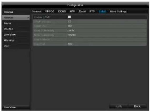
SNMP
text_image
Configuration General PFPOE CCNS NTP Email FTP SAMP More Settings Enable CMM Mail Windows V2 Send User 163 Send Connection 5000K File Connection 27486 Send Adder 162 Send Mail 162 Add Back Live View| Parameter | Setting |
| Enable SNMP | Activate the checkbox to create a connection to SNMP software |
| SNMP Version | Version of the SNMP system |
| SNMP Port | Enter the SNMP port(Default: 161) |
| Read Community | Enter the “Key” according to the settings of your SNMP software. |
| Write Community | Enter the “Key” according to the settings of your SNMP software. |
| Trap Adresse | Enter the IP address of the SNMP manager |
| Trap Port | Enter the trap port(Default: 162) |
UPnP
| Parameter | Setting |
| Activate UPnP | Activates the automatic UPnP port forwarding in the router |
| Allocation type | The port allocation for port forwarding can be assigned automatically or manually. |
| Port type | Server port: General communication portHTTP port: Port for the HTTP protocolRTSP port: Port for the RTSP protocolHTTPS: Port for a secure HTTP protocol connection |
| Edit | Activates editing for the external port |
| External port | Port for accessing the corresponding service on the external router side |
| Allocate IP address | Internal IP address of the DVR |
| Port | Internal port for the corresponding service in the DVR |
| Status | Activity status or the corresponding port forwarding |

Note
SNMP is used for monitoring the device status. For this you need SNMP software not available from ABUS.
Confirm the settings by clicking Apply and leave the menu with Back.
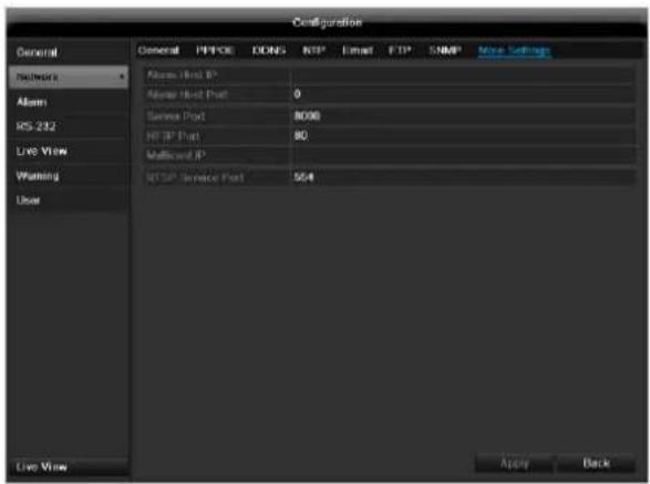
More settings
text_image
Configuration General General PFPC DDNS NTP Email FTP SNMP Move Settings Networks Alstom Address IP Alstom Host Port 0 Server Port 8090 HTTP Port 80 Multicost IP NTSP Server Port 564 Live View Apply Backfied when there is an alarm, and performs various reactions depending on the setting.
| Parameter | Setting |
| Alarm Host IP | Network address of the PC where the CMS is installed |
| Alarm Host Port | Port of your CMS Station |
| Server Port | Port for data communication (General: 8000) |
| HTTP Port | Port for web server (General: 80) |
| Multicast IP | In order to minimize traffic you can enter a Multicast IP. The IP address has to match the IP address of the PC running the CMS software. |
| RTSP Service Port | RTSP-port(Default: 554) |
| Activate HTTPS | Activates a secure connection via HTTPS |
| HTTPS port | Allocates the HTTPS communication port |
| Activate high-speed download | The outgoing network performance is increased using resources otherwise used for local OSD display. This function should only be activated temporarily, for example to speed up data back-up to a PC. |

Note
Server port 8000 and HTTP port 80 are the standard ports for remote clients and remote Internet browser access.

Note
With Alarm Host IP/Port you configure the address of your CMS software. The CMS software is noti-
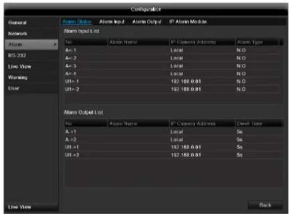
Alarm
Alarm status
text_image
Configuration General Network Alarm RS-232 Live View Warning User Alarm Status Alarm Input Alarm Output IP Alarm Module Alarm Input List No Alarm Name IP Camera Address Alarm Type A<1 Local N.O A<2 Local N.O A<3 Local N.O A<4 Local N.O UI< 1 192 168.0.01 N.O UI< 2 192 168.0.01 N.O Alarm Output List No Alarm Name IP Camera Address Delivery Time A <1 Local 5s A >2 Local 5s UI >1 192 168.0.01 5s UI >2 192 168.0.01 5s BackHere you see a list with all the alarm inputs and outputs and their current status.
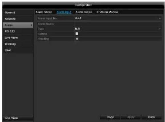
Alarm input
text_image
Configuration General Network Alarm RS-232 Live View Warning User Alarm Status Alarm Input Alarm Output IP Alarm Module Alarm Input No. A=1 Alarm Name Type N.O Setting Handling Live View Copy Apply Back- Select a reaction in the case of an alarm by clicking the 'Setting' symbol for "Handling".
| Parameter | Setting |
| Alarm Input No. | Select the alarm input to make the settings |
| Alarm Name | Enter a clear description here (e.g. door contact on warehouse) |
| Type | N.O.: Normally open circuitN.C.: Normally closed circuit |
| Setting | Activates a response |
| Response | Edits a response |
- Activate the alarm input by ticking the checkbox for "Setting".
- Define the response of the recorder when there is an alarm under "Handling".
- Click Copy to apply these settings for other cameras.
- Confirm the settings by clicking Apply and leave the menu with OK.
Handling
TAB Trigger channel
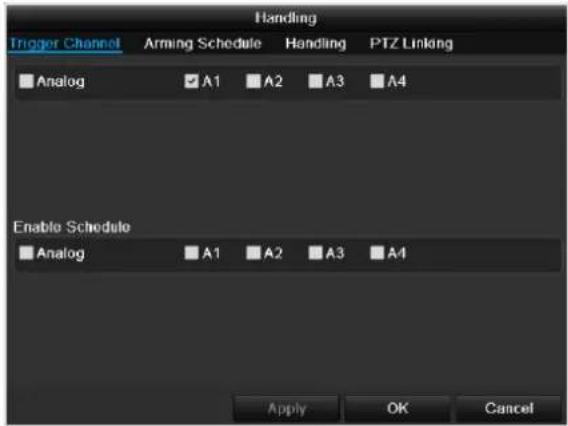
text_image
Trigger Channel Arming Schedule Handling PTZ Linking Analog A1 A2 A3 A4 Enable Schedule Analog A1 A2 A3 A4 Apply OK CancelTick a checkbox to select which camera channel is triggered in the case of an alarm.
TAB Arming schedule
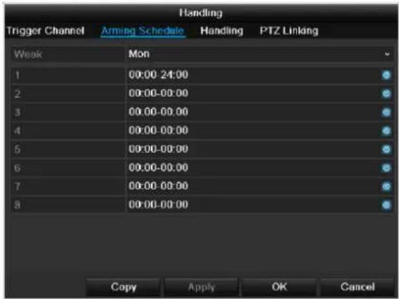
text_image
Handling Trigger Channel Arming Schedule Handling PTZ Linking Weak Mon 1 00:00 24:00 2 00:00-00:00 3 00:00-00:00 4 00:00-00:00 5 00:00-00:00 6 00:00-00:00 7 00:00-00:00 8 00:00-00:00 Copy Apply OK Cancel- Define the time at which the responses selected in the TAB "Handling" are activated when there is an alarm.
- Click Copy to apply these settings for other days of the week or the entire week.
TAB Handling
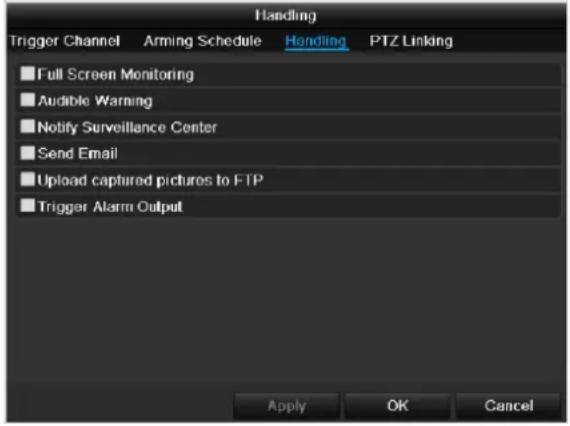
text_image
Handling Trigger Channel Arming Schedule Handling PTZ Linking Full Screen Monitoring Audible Warning Notify Surveillance Center Send Email Upload captured pictures to FTP Trigger Alarm Output Apply OK CancelDefine the response in the case of an alarm:
| Parameter | Setting |
| Full Screen Monitoring | A message appears on the monitor. |
| Audible Warning | The device emits a repeating tone. |
| Notify Surveillance Center | Sends an alarm signal to a PC with ABUS CMS software. The software must be enabled and the recorder set to surveillance mode on the PC. |
| Send E-Mail | An e-mail is sent to a specific e-mail address (see page 96). |
| Trigger Alarm Output | see also page Fehler! Textmarke nicht definiert. |
Confirm the settings by clicking Apply and leave the menu with OK.

Note
To record with the aid of an alarm, you must set up the schedule under Recording (see p. 109).
TAB PTZ
| Parameter | Setting |
| PTZ | Select a PTZ camera |
| Open presets | A preset (preset item) can be opened |
| Preset | Selects a preset |
| Start patrol | A patrol can be started |
| Patrol | Patrol selection |
| Start pattern | A pattern can be opened |
| Pattern | Pattern selection |
Alarm output
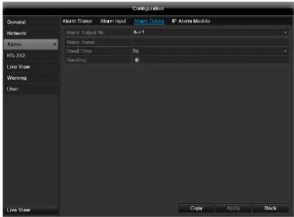
text_image
Configuration General Network Alarms RS-232 Live View Warning User Alarm Status Alarm Input Alarm Output IP Alarm Module Alarm Output No A->1 Alarm Name Dwell Time 5s Handling Live View Copy Apply Back- Select an alarm output to be configured in the drop-down menu under "Alarm Output No.".
- Assign any name to the alarm output in "Alarm Name".
- In "Dwell Time", select how long the alarm is triggered for.
- In "Handling", select the schedule for the alarm output.
- Click Copy to apply these settings for other alarm outputs.
- Confirm the settings by clicking Apply and leave the menu with OK.
RS-232
Currently no functioning.
Live view
See page 87.
Warning
text_image
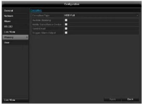
Configuration General Network Alarm RS-232 Live View Warning User Default Description Type HDD Full Audited Warning Notify Surveillance Center Send Email Trigger Alarm Output Live View Apply Backi
Note
Enter the trigger under "Exception Type", for example:
- HDD Full
- Disconnected
• Video signal not normal
• Video input/output signals not equal
After doing this, specify the device behaviour.
Confirm the settings by clicking Apply and leave the menu with Back.
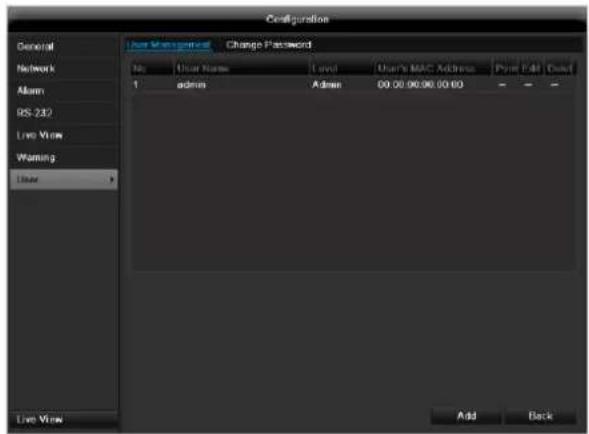
User
text_image
Configuration General Network Alarm RS-232 Live View Warning User Live View User Management Change Password No User Name Load User's MAC Address Print Edit Delete 1 admin Admin 00:00:00:00:00 00:00:00:00:00 00:00:00:00:00 00:00:00:00:00 00:00:00:00:00 00:00:00:00:00 00:00:00:00:00 00:00:00 Add Back
Warning
Note down the admin password.
The following password is preset
"1 2 3 4 5"
You can add new users, delete existing users and change the settings in the "User Management" menu.
- To add a new user, select Add.
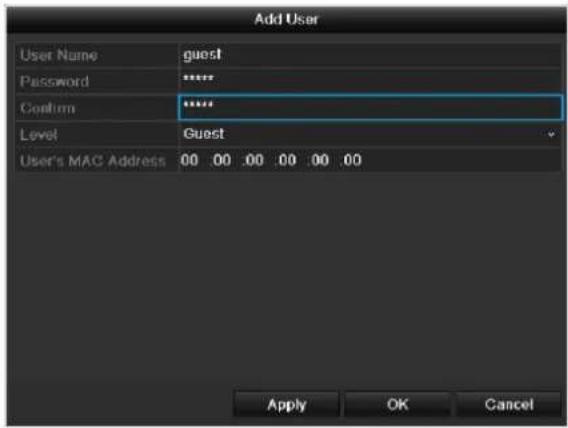
text_image
Add User User Name guest Password ****** Confirm ****** Level Guest User's MAC Address 00 00 00 00 00 00 Apply OK Cancel| Parameter | Setting |
| User Name | Unique identification |
| Password | Access code for the device (device management)Note: Change all passwords on a regular basis, using a combination of letters and numbers. Note down all passwords in a safe place. |
| Confirm | Enter the access code again here |
| Level | IMPORTANT:More access rights can be set on the Manager level than on the User level. |
| User's MAC Address | MAC address of the network adapter on the PC of the corresponding userNote:This limits access to the PC whose MAC address is entered here! |
- Enter the name and password and confirm the password in the field below.
- Select the level and enter the MAC address.
- Confirm the settings by clicking Apply.

Warning
Pay attention to the instructions below on assigning access rights.
Permission
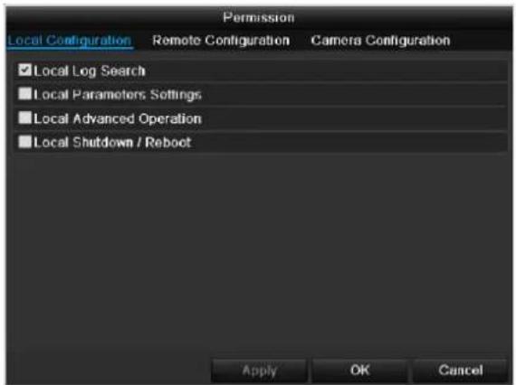
Control the access rights of the user by clicking the "Permission" symbol. Only the access data of users added manually can be changed:
text_image
Permission Local Configuration Remote Configuration Camera Configuration ✓ Local Log Search ■ Local Parameters: Settings ■ Local Advanced Operation ■ Local Shutdown / Reboot Apply OK Canceli
Note
The user can make the settings locally (i.e. on the device) or change the parameters.
The user can access the device via the network connection.
The "Camera Permission" tab is used to set access rights for individual cameras (network or local).
| Parameter | Setting |
| Local Configuration | Local Log SearchLocal Parameters SettingsLocal Advanced OperationLocal Shutdown / Reboot |
| Remote Configuration | Remote Log SearchRemote Parameters SettingsRemote Serial Port CtnrolRemote Video Output CntrolTwo-way AudioRemote Alarm ControlRemote Advanced OperationRemote ShutDown / Reboot |
| Camera Configuration | Camera Permission |

Warning
Change the general settings of the user (name, password, level, MAC address) by clicking the "Edit" symbol or in the TAB "Change password".
Camera
Camera
TAB analog cameras
| Parameter | Setting |
| Camera no. | Shows the camera number |
| Camera name | Shows the camera name |
| Status | Automatic video signal state detection |
| Live | A preview of the live image can be displayed here |
| Status | Channels can be activated or deactivated here |
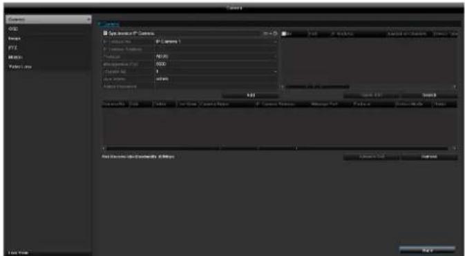
TAB IP cameras
text_image
System1 P-Current P-Current 1 P-Current 2 P-Current 3 P-Current 4 P-Current 5 P-Current 6 P-Current 7 P-Current 8 P-Current 9 P-Current 10 P-Current 11 P-Current 12 P-Current 13 P-Current 14 P-Current 15 P-Current 16 P-Current 17 P-Current 18 P-Current 19 P-Current 20 P-Current 21 P-Current 22 P-Current 23 P-Current 24 P-Current 25 P-Current 26 P-Current 27 P-Current 28 P-Current 29 P-Current 30 P-Current 31 P-Current 32 P-Current 33 P-Current 34 P-Current 35 P-Current 36 P-Current 37 P-Current 38 P-Current 39 P-Current 40 P-Current 41 P-Current 42 P-Current 43 P-Current 44 P-Current 45 P-Current 46 P-Current 47 P-Current 48 P-Current 49 P-Current 50 P-Current 51 P-Current 52 P-Current 53 P-Current 54 P-Current 55 P-Current 56 P-Current 57 P-Current 58 P-Current 59 P-Current 60 P-Current 61 P-Current 62 P-Current 63 P-Current 64 P-Current 65 P-Current 66 P-Current 67 P-Current 68 P-Current 69 P-Current 70 P-Current 71 P-Current 72 P-Current 73 P-Current 74 P-Current 75 P-Current 76 P-Current 77 P-Current 78 P-Current 79 P-Current 80 P-Current 81 P-Current 82 P-Current 83 P-Current 84 P-Current 85 P-Current 86 P-Current 87 P-Current 88 P-Current 89 P-Current 90 P-Current 91 P-Current 92 P-Current 93 P-Current 94 P-Current 95 P-Current 96 P-Current 97 P-Current 98 P-Current 99 P-Current 100| No. | Shows the camera number |
| Camera address | Shows the set IP address of the camera |
| Log | Selecting the log |
| Managing the port | Setting for http ports of the cam-era |
| Channel no. | Channel number display |
| User name | Enter the user names of the cam-era here |
| Admin password | Enter the administrator password here |
| Display mode | Settings for displaying the camera name and date |
Click on Add to link a camera to the system.
Click on "Search" to search the network for the available ABUS network cameras. Mark the required cameras and then click on "Quick Add" to link the cameras.

Note
In some cases, you need to enter the user names, password and http port by hand afterwards.
The available bandwidth shows you how much bandwidth is still available for setting up the network camera.
OSD
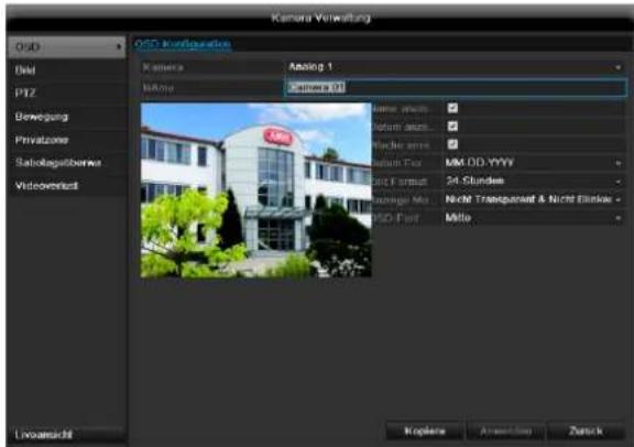
| Camera | Camera to be set |
| Camera Name | Allocation of camera name |
| Display Name | Activate / deactivate display of camera name in the live view |
| Display Date | Activate / deactivate display of date in the live view |
| Display weekday | Displays the weekday in the live cast |
| Display Week | Activate / deactivate display of week in the live view |
| Date Format | Selection of date display type |
| Time format | Choose between 24-hour and 12-hour time format for display |
| Position | The position of the text overlay can be set directly in the preview image using the mouse. Simply use the mouse to drag the corresponding text overlay frame. |
| Time Format | 12 hours / 24 hours |
| Display Mode | Settings relating to the presentation of camera name and date |
Image

Note
You can also start the patrol directly in the live image of the respective network camera.
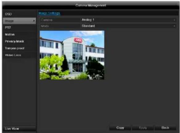
text_image
Camera Management Image Settings Camera Analog 1 Mode Standard Motion Privacy Mask Tempor proof Video Lock Live View Copy Apply BackSelect the camera channel to be processed at "Camera". Adapt the camera image to light conditions at "Mode" by means of specified settings or with user-defined settings.
PTZ

Note
Here you can set up presets and patrols for the TVIP2xxxx network cameras.
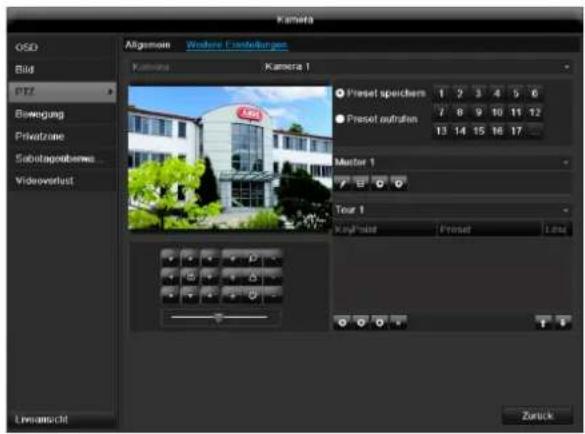
text_image
Kameta Aflgenom Wolters Forderungen Kamena Kamera 1 Preset speichens 1 2 3 4 5 6 7 8 9 10 11 12 Preset outrahen 13 14 15 16 17 Master 1 Tour 1 Key mist Preset Late Liveschelt ZurückSaving and retrieving presets
-
Use the arrow buttons to move the network camera to the required image section and save the position, for example as Preset 1
-
Click on Call up to move to Preset 1.
Setting up and calling up patrols
-
Create several presets to use for the patrol
-
Click on + to select a preset
-
Add more presets to set up the required patrol.
-
Then click on the play symbol to start the patrol.
Motion
Select the camera channel under "Camera".
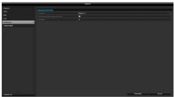
text_image
Display MOS File PDF Display Image Display Preview Preview 1 Preview displayed in the image Preview 2 Preview 3 Preview 4 Preview 5 Preview 6 Preview 7 Preview 8 Preview 9 Preview 10 Preview 11 Preview 12 Preview 13 Preview 14 Preview 15 Preview 16 Preview 17 Preview 18 Preview 19 Preview 20 Preview 21 Preview 22 Preview 23 Preview 24 Preview 25 Preview 26 Preview 27 Preview 28 Preview 29 Preview 30 Preview 31 Preview 32 Preview 33 Preview 34 Preview 35 Preview 36 Preview 37 Preview 38 Preview 39 Preview 40 Preview 41 Preview 42 Preview 43 Preview 44 Preview 45 Preview 46 Preview 47 Preview 48 Preview 49 Preview 50 Preview 51 Preview 52 Preview 53 Preview 54 Preview 55 Preview 56 Preview 57 Preview 58 Preview 59 Preview 60 Preview 61 Preview 62 Preview 63 Preview 64 Preview 65 Preview 66 Preview 67 Preview 68 Preview 69 Preview 70 Preview 71 Preview 72 Preview 73 Preview 74 Preview 75 Preview 76 Preview 77 Preview 78 Preview 79 Preview 80 Preview 81 Preview 82 Preview 83 Preview 84 Preview 85 Preview 86 Preview 87 Preview 88 Preview 89 Preview 90 Preview 91 Preview 92 Preview 93 Preview 94 Preview 95 Preview 96 Preview 97 Preview 98 Preview 99 Preview 100Select the checkbox for motion detection.
The motion detection in the network camera must also be activated. For further details, refer to the network camera manual.

Note
In order to record using the motion recognition, you must set the time plan at recording (see p. 109).
Handling
Trigger Channel
When "Reaction" is clicked, the TAB Trigger channel appears (only with motion recognition):
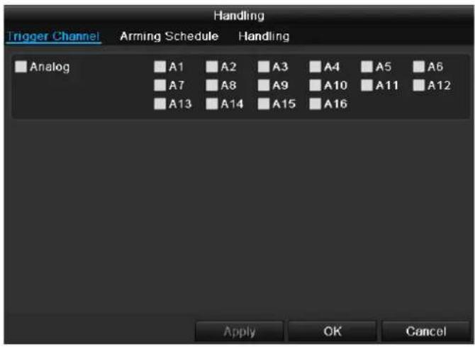
text_image
Trigger Channel Arming Schedule Handling Analog A1 A2 A3 A4 A5 A6 A7 A8 A9 A10 A11 A12 A13 A14 A15 A16 Apply OK CancelSelect one or more camera channels that should carry out a reaction in the event of an alarm. Confirm the settings by clicking Apply and leave the menu with OK.
Armin Schedule
Select the TAB Arming Schedule.
Here you set the times when the reactions in the TAB Reaction are triggered.
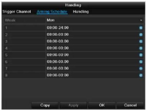
text_image
Trigger Channel Arming Schedule Handling Week Mon 1 00:00-24:00 2 00:00-00:00 3 00:00-00:00 4 00:00-00:00 5 00:00-00:00 6 00:00-00:00 7 00:00-00:00 8 00:00-00:00 Copy Apply OK Cancel- Select the day and enter the schedule.
i
Note
You can define up to 8 time periods (each from 00:00 to 00:00). The times in the individual periods must not overlap.
- Select whether the settings should be applied to all days of the week with using Copy.
- Confirm the settings by clicking Apply and leave the menu with OK.
Handling
Click on the TAB Handling.
Here you can configure the behavior of the recorder during a detected event (for example: motion got detected) by clicking the respective check box.

text_image
Handling Trigger Channel Arming Schedule Handling Full Screen Monitoring Audible Warning Notify Surveillance Center Send Email Trigger Alarm Output Apply OK Cancel| Parameter | Notification |
| Full Screen Monitoring | The camera is displayed as a full-screen picture in live cast |
| Audible Warning | The device emits a repeating tone |
| Notify Surveillance Center | Sends an alarm signal to a PC with the ABUS CMS software. For this, the software must be running and the recorder must be in surveillance mode. |
| Send E-Mail | An e-mail is sent to a specific e-mail address (see page 96) |
| Trigger Alarm Output | see page 96 |
- Confirm the settings by clicking Apply and leave the menu with OK
Private zone
The private zone function allows sections of the video image to be masked. Start by selecting a camera. Activate the private zone function using the check box. Mark a rectangle at the left of the preview area. Up to four private zones can be configured. There are buttons on the right side which allow you to delete individual masks or all masks.
Tamper surveillance
The tamper surveillance function allows you to monitor the entire video image, or a section within the video image, for masking. Start by selecting a camera. Activate the tamper surveillance function. Mark a section within the preview window for monitoring (alternatively, mark the entire image). Schedules for monitoring and reactions when the camera is masked can be programmed as reactions (similar to motion detection). The adjustable sensitivity controls the reaction speed in the event of masking. The delete button removes the section to be monitored.
Video signal loss
In the event of video signal loss, a corresponding reaction can be triggered. Start by selecting a camera. Activate the function using the check box. Schedules for monitoring and reactions when the video signal is lost can be programmed as reactions (similar to motion detection).
Record
Setting up
Open the main menu and click on record:
Schedule
The schedule is used to specify the recording times and triggers (recording type) for the cameras. Click on the "Schedule" tab:

Note
Because there is no difference between the settings for the TABs record and instant image, these are only listed once.
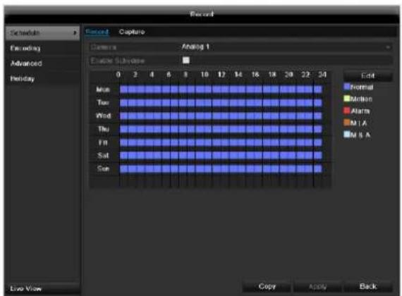
text_image
Record Schedules Encoding Advanced Holiday Record Capture Camera Analog 1 Enable Sequence 0 2 4 6 8 10 12 14 16 18 20 22 24 Mon Normal Tue Motion Wed Alarm Thu M I A Fri M S A Sat Sat Sun Edit Normal Motion Alarm M I A M S A Live View Copy Apply BackIn the OSD, the hours of the respective days are listed from left to right (the days are listed from top to bottom). A colour key is shown underneath the days (i.e. the recording periods in the schedule are shown in colour according to the trigger (recording types)).
| Colour symbol | Key |
| Blue | Normal recording: Period in hours |
| Yellow | Motion detection |
| Light blue | Motion detection and alarm |
| Red | Alarm |
| Grey | No selection |
| Brown | Motion or alarm |
- Select the camera and click on the check box Enable Schedule.
- Click on Edit to specify the type and duration of the time plan
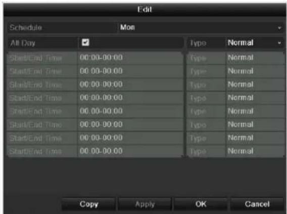
text_image
Edit Schedule Mon All Day ✓ Type Normal Start/End Time 00:00-00:00 Type Normal Start/End Time 00:00-00:00 Type Normal Start/End Time 00:00-00:00 Type Normal Start/End Time 00:00-00:00 Type Normal Start/End Time 00:00-00:00 Type Normal Start/End Time 00:00-00:00 Type Normal Start/end Time 00:00-00:00 Type Normal Copy Apply OK Cancel- Define the day to be set in the pull-down menu at 'Schedule'.
- Activate/deactivate 'All day'. If the full day is active, no definite times can be entered as the setting is now valid for the whole day.
- To make specific time settings, deactivate the "All Day" box.

Application example
Recording should run from 11:00 to 07:00. 2 time zones must be set up for this:
- 11:00 AM - 24:00PM
-
00:00 AM - 7:00 AM
-
Specify the recording type in the drop-down menu:
-
Time
- Motion detection
- Alarm
- Motion detection or alarm
• Motion detection and alarm

Note
To record using motion detection or the alarm, you must first set this up in the Camera menu (see p. Fehler! Textmarke nicht definiert. "Setting up of zones") or Configuration (see p. Fehler! Textmarke nicht definiert. "Alarm").
- When making a specific time setting, you can define up to 8 time periods (each from 00:00 to 24:00). The times in the individual periods must not overlap.

Note
The "Time" recording type defines the time window where a recording is made.
The other events (e.g. motion detection and/or alarm) only trigger the recording after the specific event has occurred.
Settings
- At Copy you can take on this setting for other days on the whole week.
- Finalize your settings in the record screen with Apply and then OK.
Encoding
TAB Record
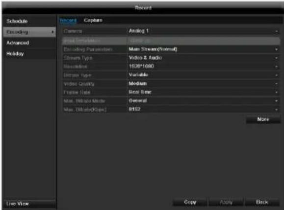
text_image
Record Schedule Encoding Advanced Holiday Record Capture Camera Analog 1 Real Estimation Home op Including Parameters Main Stream(Normal) Stream Type Video & Audio Reconstruction ISO*1080 Ultrate Type Variable Video Quality Medium Frame Rate Real Time Max. (Video Mode) General Max. (Absolute(Suppl) #152 More Live View Copy Apply BackThe following setting options are available in this sub-menu:
Confirm the settings by clicking on Apply and exit the menu with OK.
| Pre-record | Recording period before an alarm (in seconds) |
| Post-record | Recording period after an alarm (in seconds) |
| Record Audio | Audio record yes/no |
Confirm the settings by clicking on Apply and leave the menu with OK.
TAB Captured
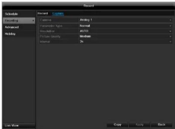
text_image
Record Schedule Recording Advanced Holiday Record Camera Analog 1 Parameter Type Normal Resolution AUTO Picture Quality Medium Internal 2s Live View Copy Apply BackThe following parameters are adjustable:
| Camera | Camera to be set |
| Parameter Type | Schedule or event |
| Resolution | Auto, 4CIF(704x576), CIF(352x288), QCIF(176x144) |
| Picture Quality | different qualities +++: middle quality +++++: high quality |
| Interval | Single images are saved every 1-5 seconds according to event or time plan |
Confirm the settings by clicking Apply and leave the menu with Back.
Advanced settings
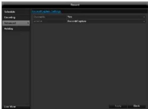
text_image
Record Schedule Encoding Advanced Holiday RecordCapture Settings Ownership Yes aDATA RecordCapture Live View Apply Back| Overwrite | You can specify whether older recordings are deleted when the HDD memory is full |
| eSATA | Specify if an eSATA hard disc connected by USB should be used for exporting, or for additional recording/image storing. |
Holidays
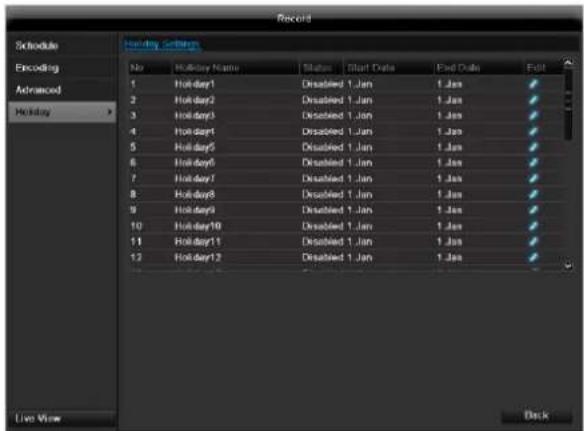
text_image
Record Schedule Encoding Advanced Holiday No.Holiday Name Status Start Date End Date Exit 1 Holiday1 Disabled 1.Jan 1.Jan 2 Holiday2 Disabled 1.Jan 1.Jan 3 Holiday3 Disabled 1.Jan 1.Jan 4 Holiday4 Disabled 1.Jan 1.Jan 5 Holiday5 Disabled 1.Jan 1.Jan 6 Holiday6 Disabled 1.Jan 1.Jan 7 Holiday7 Disabled 1.Jan 1.Jan 8 Holiday8 Disabled 1.Jan 1.Jan 9 Holiday9 Disabled 1.Jan 1.Jan 10 Holiday10 Disabled 1.Jan 1.Jan 11 Holiday11 Disabled 1.Jan 1.Jan 12 Holiday12 Disabled 1.Jan 1.Jan Live View BackIn this sub-menu, 32 different recording settings for vacations or public holidays can be applied.
To apply these settings click on the "Edit" symbol:
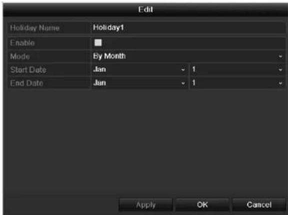
text_image
Edit Holiday Name Holiday1 Enable Mode By Month Start Date Jan 1 End Date Jan 1 Apply OK Cancel| Holiday Name | Manual name entry of the vacation or holiday |
| Enable | Activate or deactivate the set vacation |
| Mode | According to date / week / month |
| Start Date | Selection of start date / start time |
| End Date | Selection of end date / end time |
Confirm your settings with Apply and OK.
HDD
HDDs
i
Note
The device manages up to eight 3.5" SATA hard disk drives.
For additional data security, an e-SATA hard disc can be optionally connected.
Each of the installed HDDs must be initialised before the device can be used for recording. The device only detects the HDD and its assignment after initialisation has been made.

Warning
All data is deleted from the HDD during initialisation.
Ensure a data backup has been made in good time beforehand.
Installing the HDD
- Disconnect the device from the mains power and open the cover.
- Observe the applicable ESD guidelines when handling electronic devices and ensure they are earthed.
- Do not open the device in rooms with carpets or other surfaces that can become electro statically charged.
- Avoid bodily contact with all components on the PCB.

Warning
If you have questions regarding the information or cannot find the information you need, please contact your maintenance specialist.
- Install the HDD and then connect it.
- Reattach the cover and connect the device to the mains power supply.
- Switch on the device and start the HDD menu.
i
Note
If the initialised HDD is not displayed, check the connections
Click on "HDD" in the menu to define settings relating to hard disc administration
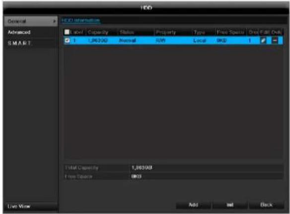
text_image
HDD Advanced SMART HDD Information Label Capacity Status Property Type Price Spots Direct Edit Only 1,00000 Normal NAV Local OKD 1 Total Capacity 1,00000 Free Spccrer 0005 Add Init Back Live ViewHDD Management parameters
| HDD information | |
| Label | Shows the internal connection number |
| Capacity | HDD capacity (in GB) |
| Status | Shows the current status of the HDD:Not initialisedNormalError |
| Property | Redundancy: Works redundant-ly for data securityRead-only: Read-only protectionR/W: Read and write |
| Type | Local: Device HDDNFS: Network HDDIf possible, avoid using NFS storage due to compatibility problems that may occur. |
| Free Space | Shows the approximate free memory for recordings |
| Group | HDD group (1 is preset)Recordings can be assigned to groups |
| Edit | Define hard disc settings (First adjust the camera groups; see also p.32) |
| Delete | Removal of the hard disc |
- Select the HDD by ticking the corresponding box.
- Start the process by clicking on Init.
- Confirm the prompt by pressing OK.
- The status bar shows the progress of the initialisation.
HDD settings of the cameras
Click on the sub-menu "Advanced".
Mode: Quote
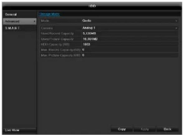
text_image
HDD General Advanced SMART Storage Mode Mode Center Camera Aiding 1 Used Record Capacity 5,120MB Used Picture Capacity 16.35/MB HDD Capacity (KB) 16KB Max Record Capacity (KB) 0 Max Picture Capacity (KB) 0 Live View Copy Apply BackSpecify the maximum recording size per camera on the hard disc.
Mode: Group
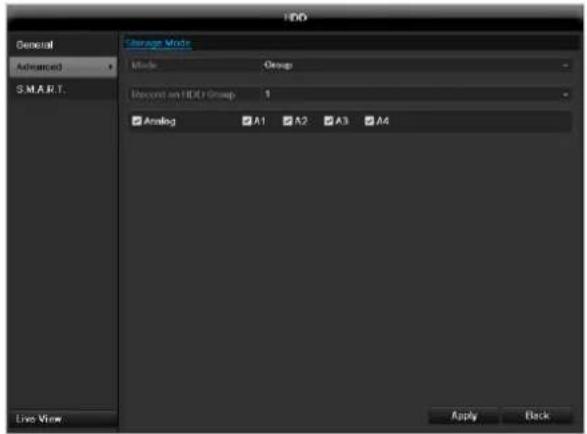
text_image
HDD General Advanced S.M.A.R.T. Storage Mode Mode Group Record on HDD Group 1 Analog A1 A2 A3 A4 Live View Apply Back- Select a hard disc group in the drop-down menu.
- By activating the check box, specify which cameras should be saved on the hard disc group.
- Click on Apply and confirm the restart in the next window with OK.
Hard disc setting

Note
To be able to define these settings, you must have allocated cameras to a hard disc group (see HDD settings of cameras).
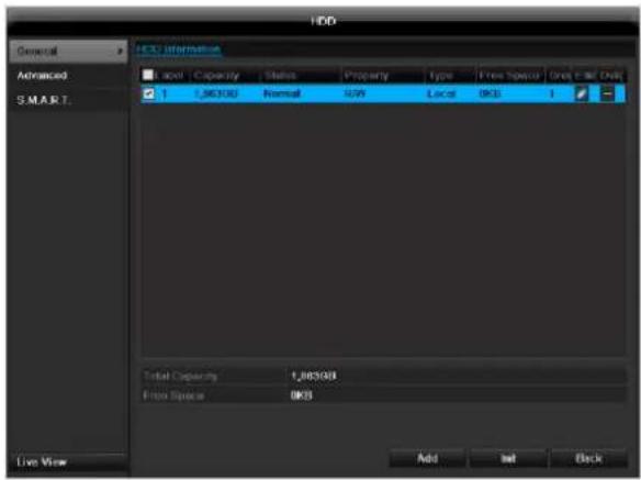
text_image
HDD General Advanced SMART. HDD Information Label Capacity Status Property Type Press Space Open Call Qty 1,26300 Normal NAV Local OKS 1 Total Capacity 1,26300 Free Space OKS Add Init Back Live ViewClick on the "Edit" symbol. A pop-up window appears:
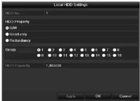
text_image
Local HDD Settings HDD No 1 HDD Property ● RW ● Read-only ● Redundancy Group ● 1 ● 2 ● 3 ● 4 ● 5 ● 6 ● 7 ● 8 ● 9 ● 10 ● 11 ● 12 ● 13 ● 14 ● 15 ● 16 HDD Capacity 1,863GB Apply OK Cancel| HDD No. | Selecting hard disc by means of internal connection number |
| HDD Property | R/W: Readable and writableRead-only: Write protectionRedundant: operating redundantly for data security. |
| Group | Selection of hard disc group |
| HDD Capacity | Hard disc memory |
Confirm the settings by clicking Apply and leave the menu with OK.

Warning:
If only one HDD is installed and this is set to "Read-only", then the device cannot make recordings.

Redundancy:
At least two HDDs are installed.
The redundant HDD makes an extra copy of the recordings. This is used as a data backup.

Warning:
If you want to use redundancy you have to activate the redundant storage in the recording menu (see also p. 110)

R/W
At least one HDD must have the R/W status (Read/Write). Otherwise, no recordings are possible.
Checking the HDD status
The status of each HDD can be checked in the "Maintenance" menu. S.M.A.R.T. information (Self-Monitoring, Analysis and Reporting Technology) is stored in the log data.
- Call up the log file and search according to the information/S.M.A.R.T. HDD (see page 114).
Setting up the HDD alarm
You can specify alarms to inform you of HDD errors.
- To do this, call up Warning in the "System Settings" menu (see page 103).
S.M.A.R.T.
S.M.A.R.T. means Self-Monitoring Analysis and Reporting Technology.
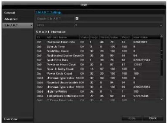
text_image
HDD General Advanced SMART > HDD 1 SMART Information ID: Alt Data Range Status Range Threshold Value Period New Value 0x1 Raw Road Error Rate OK 1 44 78 63 52843883 0x2 Spin Up Time OK 3 0 100 100 0 0x3 StandClips Count OK 32 20 100 100 0 0x4 Reallocated Sector Count OK 32 36 99 99 94 0x7 Suck Error Rate OK / 30 78 60 5739371543 0x8 Power de Hours Count OK 32 0 87 87 12197 0x9 Spin Up Rely Count OK 13 97 100 100 0 0x10 Power Circle Count OK 32 20 100 100 100 0x11 Unknown Type Value 16CK OK 32 99 100 100 0 0x12 Reported Uncorrectable EOK OK 32 0 94 94 8 0x13 Unknown Type Value 18CK OK 32 0 100 99 4795231813 0x14 Highly Rated OK 34 0 1 1 103 0x15 Temperature Difference EOK OK 32 45 69 49 527175583 0x16 C-Frame Error Rate OK 31.5 6 100 100.5 Live View Action BackInformation on the hard disc status is displayed in this sub-menu.
This information helps to recognize hard disc errors. For this reason, do not deactivate this feature if possible.

Note
The log files saved for S.M.A.R.T. can be found in the menu Maintenance at "Log search" (see page 117).
Playback
Press Configuration in the main menu and then Play-back to search for video recordings after an event or a marking, or to view your saved images.
Continuous Recording
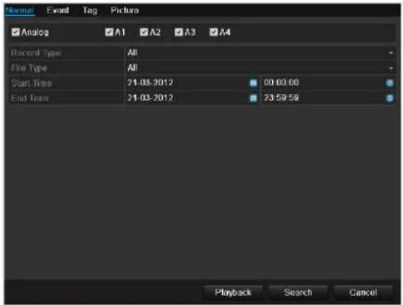
text_image
Normal Event Tag Picture Analog A1 A2 A3 A4 Recent Type All File Type All Start Time 21-03-2012 00:00:00 End Time 21-03-2012 23:59:59 Playback Search CancelThe following settings are available:
| A1 - A4 | Camera to be set |
| Record Type | Schedule, motion detection, alarm or motion detection and/or alarm, manual recording, all |
| File Type | Locked, unlocked, all |
| Start Time End Time | Enter the date and time |
- Click on Search to search for recordings with the corresponding settings. The results are then shown:
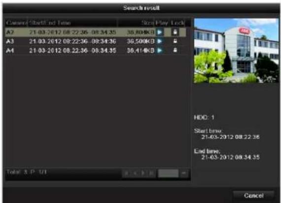
text_image
Search result General Start/End Time Start Play Lock A2 21-03-2012 08:22:36 - 08:34:35 36.80KB A3 21-03-2012 08:22:36 - 08:34:36 36.50KB A4 21-03-2012 08:22:36 - 08:34:35 36.41KB Total: & P: U1 HDC: 1 Start time: 21-03-2012 08:22:36 End time: 21-03-2012 08:34:35 Cancel- Select the recording by clicking on the line and then on "Play"-symbol.
i
Note
You can return to events search at any time in the playback mode by performing a right click and selecting 'Video Search'.
i
Note
The sub-menus 'Tag' and 'Picture' are almost identical with the menu described above and are therefore not listed separately.
In the sub-menu 'Tag', searching does not take place according to recording type, rather according
to identification or a keyword of the markings' name
Event
Please klick on the TAB „Event“.
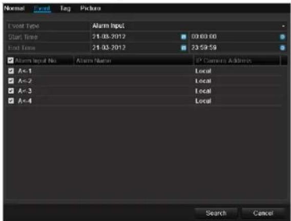
text_image
Normal Event Type Start Time End Time Alarm Input Alarm Name IP Camera Address Local Local Local Local Search CancelA list with all alarm inputs is displayed.
Select at 'Event type' whether the search should take place at alarm 'Alarm input' or motion 'Motion recognition' after recording.
Select one or more alarm inputs by activating the check box.
Klick on Search.
Select one of more alarm recordings on the list that appears. Click on Details to receive more exact information on the recordings.
Marking
Click on the "Marking" tab.
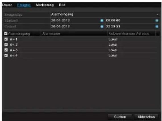
Select one or more network cameras by activating the checkbox.
Click on Search.
Select one or more markings from the list which appears. Click on Details to obtain more information about the markings.
Image
Click on the "Image" tab.
Settings
Select one or more network cameras by activating the checkbox.
Click on Search.
Select one or more images from the list which appears.
Click on Details to obtain more information about the images.
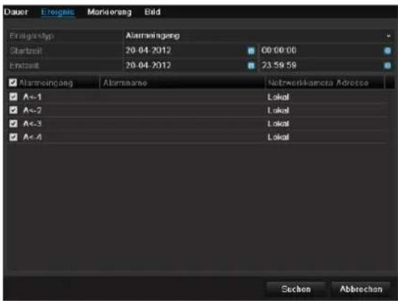
This menu is used for device maintenance, and should only be operated by experienced users.
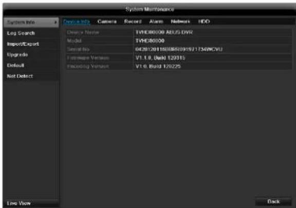
text_image
System Maintenance System Info Device Info Camera Record Alarm Network HDD Log Search Device Name TVHD80000 ABUS DVR Model TVHD80000 Device No. 0429120118036820915/17349VCVU Framework Version V1.1.0, Dual 120315 Encoding Version V1.0, Build 120225 Upgrade Default Not Detect Live View Back| Menu | Setting | P. |
| System Info | Device information (serial number, firmware status etc.) | 117 |
| Log Search | A search of recordings or information (S.M.A.R.T. HDD status) can be made in the log file according to certain criteria (alarms, exceptions, operation or information). | 117 |
| Import/Export | Used to export or import the settings | 118 |
| Upgrade | Carries out a firmware upgrade | 118 |
| Default | System reset | 119 |
| Network | Displays the transmission and reception rate of the recorder | 119 |
System Info

text_image
System Maintenance System info Device info Camera Record Alarm Network HDD Log Search Device Name TVHD00000 ADUS DVR Model TVHD00000 Serial No. 0420120158888291971735WCVU Hardware Version V1.1.0, Build 120215 Loading Version V1.0, Build 12/225 Live View Back
Note
The information menu shows the technical data for the device and information on the various settings of the cameras, recording etc.
This can be useful for support queries, for example.
Log Search
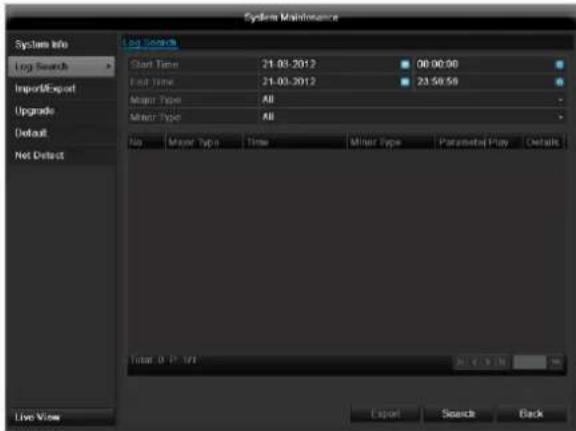
text_image
System Maintenance System Info Log Search Import/Export Upgrade Default Not Detect Log Search Start Time 21.03.2012 00:00:00 End Time 21.03.2012 23:58:59 Major Type All Minor Type All No Major Type Time Minor Type Parametal Play Details Total: 0.17.197 Export Search Back
Note
An event search can be made according to the following main types, events and parameters:
• All
- Alarm
- Exception
- Operation
- Information
| Filter1 | Filter2 |
| All | - |
| Alarm | AllAlarm Input / OutputStart / Stop Motion DetectionStart / Stop Tamper-proof |
| Exception | AllVideo Loss SignalVideo Signal ExceptionIllegal LoginHDD FullHDD ErrorIP ConflictedNetwork DisconnectedRecord / Capture ExceptionInput / recording resolution mismatch |
| Operation | All |
| Power OnAbnormal ShutdownStart / Stop AudioLocal Operation, e.g.:Shutdown / Reboot / Login / Logout / Configure Parameters / Upgrade / Start RecordingRemote Operation, e.g.: Export Record File / Alarm Arming / ... | |
| Information | AllLocal HDD InformationHDD S.M.A.R.T.Start / Stop RecordingStart / Stop CaptureDelete Expired RecordNetHDD Information |
- Select the event you wish to search for in the log, then select the sub-parameter.
- Enter the date and time under "Start Time" and "End Time", then click on Search.
- The results are then displayed:
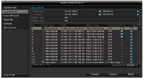
text_image
System Manager System Info Long Search Report/Request Upgrade Default Net Default User Tools Start Event 24.03.2012 24.03.2012 24.03.2012 Auto Factor All Auto Factor All User Tools Name Model Type Time User Type Parameters Field Options 1 2 3 4 5 6 7 8 9 10 11 12 13 14 15 16 17 18 19 20 21 22 23 24 25 26 27 28 29 30 31 32 33 34 35 36 37 38 39 40 41 42 43 44 45 46 47 48 49 50 51 52 53 54 55 56 57 58 59 60 61 62 63 64 65 66 67 68 69 70 71 72 73 74 75 76 77 78 79 80 81 82 83 84 85 86 87 88 89 90 91 92 93 94 95 96 97 98 99 100- The pages are changed using the navigation bar:

(1) (2)
(3) (4)
(5)
(6)

Note
To scroll forwards or backwards press (3) or (2). To jump to the first or last page press (4) or (1). To go to a specific page number enter it in (5) and confirm by clicking (6).
- Click on Details to see more detailed information.
- Click on Play to start the recording for the event, when necessary.
- Click on Export to back up the log file on a USB medium.
Import / Export
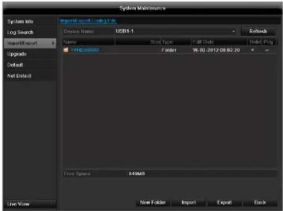
text_image
System Maintenance Import Export Coding File Device Name: USB1-1 Refresh Name: Size Type: Edit Date: Edit Play TBD00003 Folder: 16.02.2012.08.02.30 - From Options: 849MB New Folder Import Export Back Log Search ImportExport Upgrade Default Net Detect Live View
Note
The configuration data contains all settings made on the device since the start of operation. This data can be saved on a USB medium. You can then configure another device identically, for example.
Upgrade
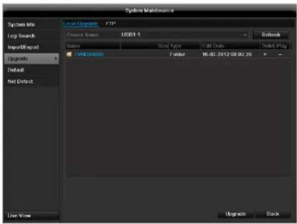
text_image
System Maintenance System Info Log Search Import/Export Upgrades Default Net Detect Local Upgrade FTP Device Name USB1.1 Refresh Name Size Type Cell Data Delete Play V8 Colors Folder 16:02:2012 GB 02:20 - Upgrade Back
Note
A device upgrade can be made from a USB device or over the network via FTP.
- Copy the upgrade file to the main directory of a USB stick.
-
Connect the USB stick to a USB port on the device.
-
Select the USB port (click on Refresh, if necessary).
- Select the upgrade file and click on Upgrade.
- Wait until the device reboots.
- Check the firmware status in the "Maintenance" menu under "System Info".
Default
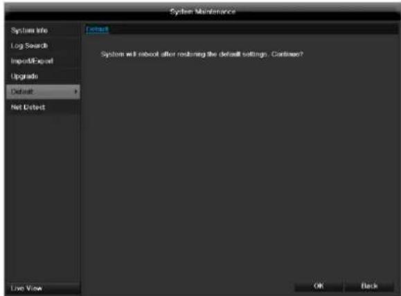
text_image
System Maintenance System Info Log Search Import/Export Upgrade Default Net Detect Default System will reboot after restoring the default settings. Continue? Live View OK Back
Note
In this process, the device is reset to the factory default settings.

Warning
All settings made since the start of operation are deleted (cameras, recording settings, PTZ, alarms etc.)!
Avoid data loss by backing up the settings in advance. These can be imported again following the system reset.
Network
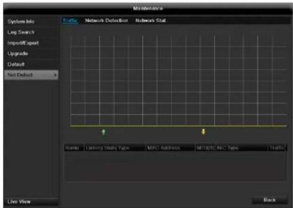
text_image
Maintenance Systems Info Log Search ImportDiff export Upgrade Default Not Defect Traffic Network Detection Network Stat Home Leisure Study Tips MAC Address MTUH1 N/C Tips Traffic Live View Black
Note
Information regarding the network traffic and network interfaces are shown here.
TAB network load
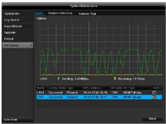
text_image
System Maintenance System info Log Search Import/Export Upgrade Default HNS Default 15Mbps LAN2 Sending: 7.42Kbps Receiving: 117Kbps Name LAN1 Successful Ethernet 09:40:35:66 1b:06 1500 100M Full-dup LAN2 Successful Ethernet 09:40:35:66 1b:07 1500 100M Full-dup BackThe amount of received and sent data is displayed graphically.
Depending on the network settings, the status and information for one or two network connections is shown in the field underneath the graph.
TAB Network Detection
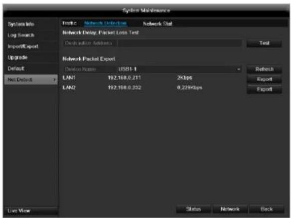
text_image
System Maintenance Syncless Info Log Search Import/Export Upgrade Default Net Default Traffic Network Connection Network Stat Network Delay Packet Lock Test Destination Address Test Network Packet Export Device Portion USB1.1 LAN1 192.168.0.211 2Kbps LAN2 192.168.0.252 8.229Kbps Refresh Export Export Live View Status Network BackIn "Destination Address", you can check the connection to another device, such as a computer ('pinging'). Enter the network address of the device to be checked (e.g. 192.168.0.25) and press Test.

text_image
Result Average delay: 27 ms Packet loss rate: 0% OKInformation on two parameters appears:
| Parameter | Setting |
| Average delay | The time the pinged device needs to reply. |
| Packet loss Rate: | Displays the percentage of packets that were not transmitted |
i
Note
If the packet loss rate is high, we recommend that the "Network Test" is repeated.
i
Note
If the packet loss rate is still high, you should check that the cables are correct and not damaged.
The higher the packet loss rate, the poorer the connection between the pinged device and recorder.
For "Network Packet Export", you can export the settings of the individual connections or – depending on the setting – the connection.
- For "Device Name", select a storage medium to save the settings to.
- Click Export.

text_image
Packet exporting CancelAfter the progress display finishes and initialization is successful, an information window appears. Close it with OK.
- Click Status to display the status of the LAN connections (connected/not connected).
- Click Network to change your network settings (see p. 96).
TAB Network Stat.
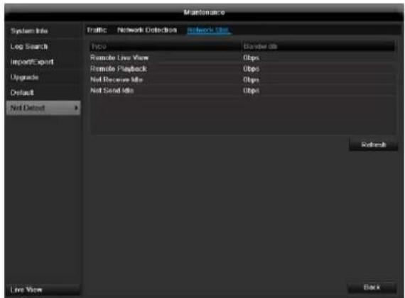
text_image
Maintenance System Info Traffic Network Detection Network dir Log Search Import/Export Upgrade Default Net Default Type: Remote Live View Remote Playback Net Resource Info Net Send Info Border dir 0bps 0bps 0bps 0bps Refresh Live View BackDisplays all used in- and outcoming bandwidth.
Video Export
Duration
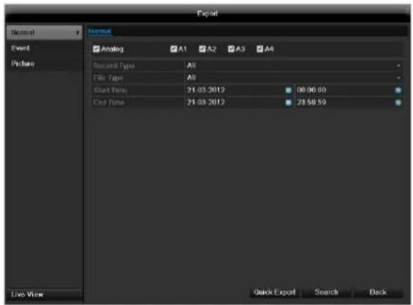
text_image
Export Normal Event Picture Analog A1 A2 A3 A4 Recent Type All File Type All Start Time 21.03.2012 06:00:00 Call Time 21.03.2012 23:58:59 Live View Quick Export Search Backi
Note
The export function is used to store important recordings on connected external media, such as:
- USB media
- USB HDD
- DVD writer
- When "Quick export" is selected, all recordings of the selected time span are exported. Please note that not more than 24 hours can be exported.
- Enter the parameters.
- Click on "Details" to limit the search
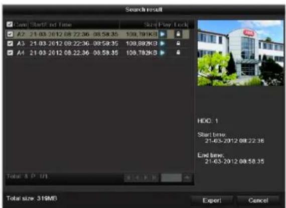
text_image
Search result Cancel Start/end Time Size/Play Lock A2 21-03-2012 08:22:36 - 08:58:35 100.791KB A3 21-03-2012 08:22:36 - 08:58:35 100.892KB A4 21-03-2012 08:22:36 - 08:58:35 100.782KB Total: A P /U HDD: 1 Start time: 21-03-2012 08:22:36 End time: 21-03-2012 08:58:35 Total size: 319MB Export Cancel- The file size of the individual recording and the total size of all found recordings are displayed.
- By clicking the "Playback" symbol you can view the respective recording.
- To block or unblock a file click on the "Lock" symbol.
- Click on Export to access the export screen.
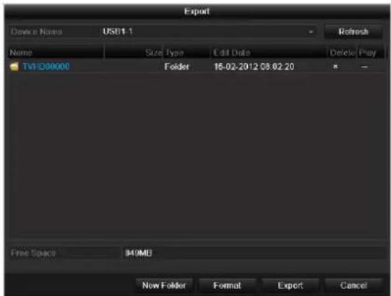
text_image
Export Device Name USB1.1 Name Size Type Edit Date Delete Play TVHD80000 Folder 16-02-2012 03.02.20 Free Space M49MB New Folder Format Export Cancel- Select the connected medium used for data storage from the drop-down menu.
- If the medium is not displayed, click on Refresh.
- If the medium is still not displayed, disconnect it from the device and reconnect the medium again. See also the manufacturer's specifications.
- Click on Export to start the export process. The progress of the export process is then displayed.
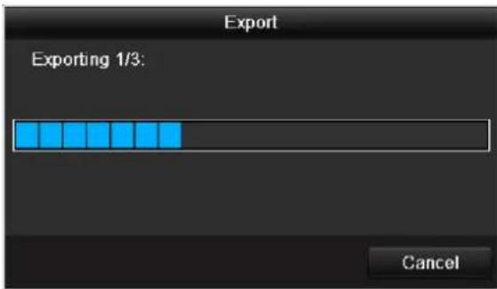
text_image
Export Exporting 1/3: Canceli
Note
After the storage process is completed, the data on the medium can be selected and played on the player (which was also backed up). In this way, you can check whether the export has been made successfully.
Event (event type 'Alarm input')
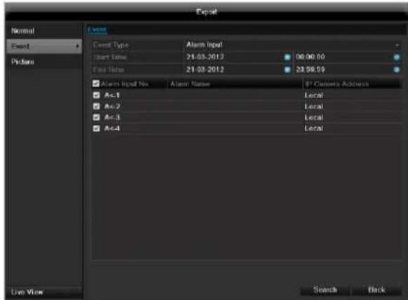
text_image
Export Event Event Type Alarm Input Start Time 21-03-2012 00:00:00 First Time 21-03-2012 23:58:59 Alarm Input No. Alarm Name IP Contexts Address A<-1 Local A<-2 Local A<-3 Local A<-4 Local Live View Search BackDefine the time span of the recording being searched for by means of the selection fields at "Start time" and "End time". Select the alarm input by activating or deactivating the check box and click Search.
Event (event type 'Motion')
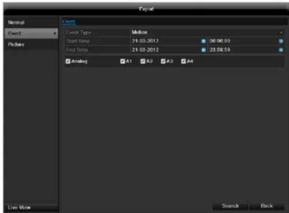
text_image
Export Normal Event Picture Event Type: Motion Start Time: 21-03-2012 00:00:00 End Time: 21-05-2012 23:59:59 Analog A1 A2 A3 A4 Live View Search BackDefine the time span of the recording being searched for by means of the selection fields at "Start time" and "End time". Select the camera by activating or deactivating the check box and click Search.
For both types of event, the following window appears after activating the Search button:
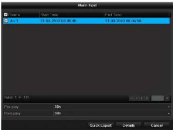
text_image
Alarm Input Source Start Time End Time A=1 21-03-2012 09:05:48 21-03-2012 08:05:50 Total 1 P 1/1 Pre-play 30s Post-play 30s Quick Export Details CancelSelect the files to be exported by activating or deactivating the check box. You can set the pre-alarm and post-alarm time at "Pre-play" or "Post-play". In this way you can define the length of your export video.
Click on Details to view the selected video. For more exact information on the Details window, see DURATION (p. 121).
i
Note
The "Pre-play" recordings can only be viewed when recording has been carried out before the alarm.
i
Note
The sub-menus "Normal" and "Picture" are similar and are therefore not listed separately.
Manual Management
Press the REC button or go to panic recording in the main menu in order to start a manual image / video recording or to switch to an alarm output.
Record
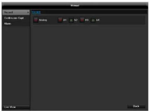
text_image
Record Continuous Capt Alarm Live View Record Analog A1 A2 A3 A4 BackSelect the camera to start manual recording by clicking the corresponding button.

Note
Click "Analog" to record all connected cameras.
Continuous Capture
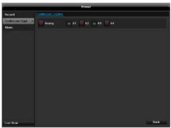
text_image
Record Continuous Capt > Alarm Continuous Captions Analog A1 A2 A3 A4 Live View BackSelect the camera to manually record continuous instant images. You can set the time interval in which these are recorded in the recording menu (see p. 109). Click the control button for this.
Alarm
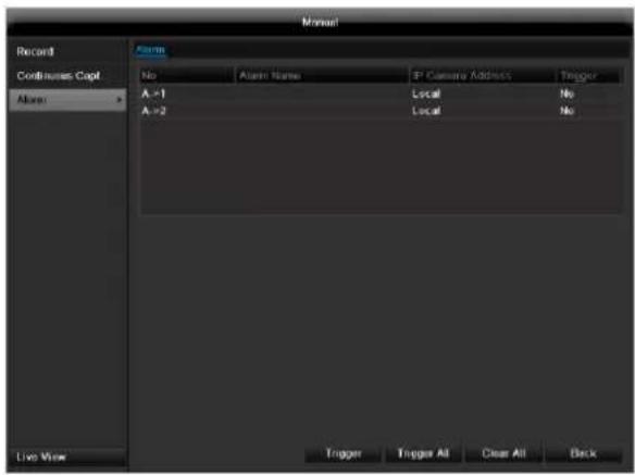
text_image
Manual Record Continuous Capt Alarm Alarm No Alarm Name P Camera Address Trigger A = 1 Local No A = 2 Local No Live View Trigger Trigger All Clear All BackIn order to switch on one of the alarm outputs, select the alarm output with a left click and click on Trigger for one, or Trigger All, to switch on all outputs. To reset the output(s) again, click on Clear or Clear all.
Shutdown
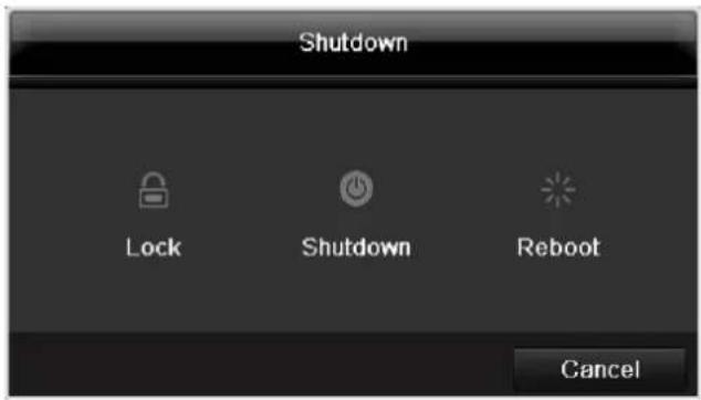
text_image
Shutdown Lock Shutdown Reboot Canceli
Note
- Select "Lock" to lock the operating menu.
- Select "Shutdown" to switch off the device.
- Select "Reboot" to reboot the system (switch off and back on).
Troubleshooting
Before calling the Service department, read the following information to determine the possible cause of a malfunction.
| Malfunction | Cause | Solution |
| No power | Mains cable not connected | Connect the mains cable securely to the socket |
| Power switch set to OFF | Turn the power switch to ON | |
| No current in the power socket | Use another device on the socket, where necessary | |
| No image | Screen not set for reception | Set the correct video input mode until an image from the recorder appears |
| Video cable not connected properly | Connect the video cable securely | |
| Connected modem is switched off | Switch on the monitor | |
| No sound | Audio cables not connected properly | Connect the audio cables securely |
| Devices connected over the audio cables are not switched on | Switch on the devices connected over the audio cables | |
| Audio connection cable is damaged | Replace the cable | |
| HDD is not working | Connection cables not connected properly | Connect the cables securely |
| HDD defective or not system-compatible | Replace with a recommended HDD | |
| USB port not working | Device not supported | Connect a compatible USB medium (USB 2.0) |
| USB hub is in use | Connect the USB medium directly | |
| Network access not possible | Network cable connections are loose | Connect the network cable |
| Network settings are incorrect (DHCP, IP address etc.) | Check the network configuration and cor-rect it, ifnecessary (see page 96). | |
| Remote control is not working | Batteries inserted with the wrong polarity or are empty | Replace the batteries. To control the device with the remote control, point it at the remote control sensor on the device |
| Remote control too far away from the re-corder | Use the remote controller within 7 metres from the device | |
| Signal blocked by obstruction between the remote control and recorder | Remove the obstruction | |
| Lighting too bright or fluorescent tubes in use? | Switch off strong fluorescent lighting in the immediate vicinity | |
| Recording not possible | No HDD or HDD is not initialised | Install and initialise the HDD |
| Sudden deactivation of the device | Temperature inside the device is too high | Clean the device and remove any obstructions from the ventilation area |
Device cleaning and care
Note
- Your device requires no maintenance.
- Protect the device from dust, dirt and moisture.
Technical data
Subject is to alterations and errors. The dimensions are approximate values.
| ABUS digital recorder | TVVR60011 | TVVR60021 |
| Video compression | H.264 | |
| Hybrid-enabled | Yes | |
| Camera inputs (analog) | 8 | 16 |
| Camera inputs (IP) | 8 | 16 |
| Camera outputs | 8 (analog, 1.0 V s-s, 75 Ω) | 16 (analog, 1.0 V s-s, 75 Ω) |
| Monitor outputs | Monitor: 1 x BNC (1.0 V p-p, 75 Ω), 1 x VGA, 1 x HDMI, 4 x BNC Spot (1.0 V p-p, 75 Ω) | |
| Operating mode | Triplex | |
| Resolution (live view) | HDMI/VGA:1920×1080/60 Hz (1080 p),1600×1200/60 Hz, 1280×1024/60 Hz,1280×720/60 Hz, 1024×768/60 Hz | |
| Resolution @ frame rate per camera (recording) | Max. 1920 x 1080 p at @ 25 fps | |
| Total frame rate | 400 fps | 800 fps |
| Network bandwidth (upload- ding) | 240 | 240 |
| Network bandwidth (downloa- ding) | 40 | 80 |
| Compression levels | Network camera-dependent | |
| Storage medium | 8 x SATA HDD | 8 x SATA HDD |
| Data backup | 3 x USB 2.0, eSATA | 3 x USB 2.0, eSATA |
| Views | 1/4/6/8/9 | 1/4/6/8/9/16 |
| Recording modes | Manual, schedule, motion detection, alarm, motion detection and alarm,motion detection or alarm | |
| Search modes | By event, date & time | |
| Alarm inputs (NO/NC) | 8 | 16 |
| Relay outputs | 2 (maximum load: 12 V DC/1 A) | 4 (maximum load: 12 V DC/1 A) |
| User levels | 2 (max. 31 users) | |
| Network access | 1 x RJ45 10/100/1,000 Mbps | |
| Parallel network access | 128 camera connections | |
| Network functions | Live view, playback, data export, settings | |
| DDNS | √ | |
| NTP | √ | |
| PTZ control | RS-485 | |
| PTZ protocols | PELCO-D | |
| Alarms | Acoustic warning, OSD signal, e-mail, CMS | |
| Audio | Line in: 1 x RCA (2.0 V s-s, 1 kΩ),Audio in 1–4: RCA (2.0 V s-s, 1 kΩ),Audio in 5–8: DB26 (2.0 V s-s, 1 kΩ),Audio out: 2 x RCA (2.0 V s-s, 1 kΩ) | Line in: 1 x RCA (2.0 V s-s, 1 kΩ),Audio in 1–4: RCA (2.0 V s-s, 1 kΩ),Audio in 5–16: DB26 (2.0 V s-s, 1 kΩ),Audio out: 2 x RCA (2.0 V s-s, 1 kΩ) |
| Control | USB mouse, remote control (not included in scope of delivery) | |
| Software | ABUS CMS software | |
| OSD languages | English, German, French, Dutch, Danish, Italian, Polish, Czech, Spanish | |
| Power supply | 100~240 V AC, 6.3 A, 50~60 Hz | 100~240 V AC, 6.3 A, 50~60 Hz |
| Power consumption | < 40 W (without HDD) | < 45 W (without HDD) |
| Operating temperature | -10 °C ~ +55 °C | |
| Dimensions (W x H x D) | 470 x 90 x 445 mm | |
| Weight | ≤ 8 kg (without HDD) | |
| Certifications | CE | |
Disposal
Information on the EU directive on waste electrical and electronic equipment
To protect the environment, do not dispose of the device with domestic waste at the end of its service life. It can be disposed of at one of the appropriate collection points in your country. Please obey your local regulations when disposing of material.

Dispose of the device in accordance with EU directive 2002/96/EC – WEEE (Waste Electrical and Electronic Equipment). If you have any questions, please contact the department of your local authority which is responsible for waste disposal. Used equipment can be disposed of, for example, by your local or municipal authority, the local waste disposal company or your dealer.
Information on handling batteries
- Always insert batteries with the correct polarity. Never attempt to recharge the batteries supplied and do not throw them into naked flames under any circumstances. Do not use different batteries at the same time (old and new, alkaline and zinc-carbon etc.). Remove the batteries if the device is not used for a long period of time. If used improperly, there is a risk of explosion and leaking batteries!
- Take environmental protection into account – used batteries should not be disposed of in domestic waste! They must be taken to a collection point for used batteries.
- Make sure that batteries are kept away from small children. Children may put batteries in their mouths and swallow them. This can cause serious harm to their health. If this happens, consult a doctor immediately.
-
Do not charge normal batteries, heat them up or throw them into naked flames (they may explode).
-
Change low batteries in good time.
- Always change all the batteries at the same time and use batteries of the same type.

Important
Leaky or damaged batteries can cause chemical burns on contact with the skin.
In this case, wear protective gloves.
▶ Clean the battery compartment with a dry cloth.
Important information on disposing of batteries
Your product uses batteries which are subject to the European directive 2006/66/EC and may not be disposed of with domestic waste.
Find out about the regulations for the separate collection of batteries which apply in your country.
Proper disposal of batteries helps prevent harm to health and the environment.
Batteries that contain harmful chemicals are labelled with these signs:

Pb = battery contains lead
Cd = battery contains cadmium
Hg = battery contains mercury
Information on the European RoHS directive
The device complies with the RoHS directive.
Compliance with the RoHS directive means that the product or component does not contain more than the following maximum concentrations of the following substances in homogeneous materials, unless the substance is part of an application that is excluded from the RoHS directive:
a) 0.1% lead (by weight)
b) Mercury
c) Hexavalent chromium
d) Polybrominated biphenyl (PBB) and polybrominated diphenyl ether
e) 0.01% cadmium (by weight)
Glossary
Overview of specialist terms
1080i
HDTV image signal with 1080 pixels and interlaced display.
16:9
Cinematographic aspect ratio on widescreen displays.
720p
HDTV image signal with 1280 x 720 pixels and progressive display.
CIF
Common Intermediate Format
Originally planned for converting PAL to the NTSC standard. CIF corresponds to a video resolution of 352 x 288 pixels (2CIF = 704 x 288 pixels; 4CIF = 704 x 576 pixels).
CINCH
Socket type used for analogue audio or CVBS video signals.
CVBS
Colour, Video, Blank and Sync – The simplest variation of video signals (also known as composite video). The image quality is comparatively low.
DDNS
Dynamic Domain Name System entry
Network service which provides and updates IP addresses of its clients in a database.
DHCP
Dynamic Host Configuration Protocol
Network protocol which allows the automatic connection of devices (clients) in existing networks. DHCP servers (e.g. Internet routers) automatically assign the IP address, network mask, gateway, DNS server and WINS server (when required). Only the automatic acquisition of IP addresses must be activated for the client in this case.
Domain
Name used for the identification of websites on the Internet (e.g. www.abus-sc.de).
Dual Stream
Dual stream is a video transmission method. A high-resolution recording and lower-resolution transmission are made over the network, for example. The main stream has a 4CIF resolution and the sub-stream has a CIF resolution.
DVR
Digital Video Recorder – A device used for recording different video and audio sources (analogue, digital). The data is compressed for recording and saved on hard disk drives (HDD).
H.264
(MPEG-4 AVC) – Standard method for the highly-efficient compression of video signals. Used on Blu-ray discs or video conference systems, for example.
HDD
Hard Disk Drive
Digital data storage on computers or DVRs.
GIGABYTE
Unit of capacity for storage media (HDD, USB, SD/MMC cards).
HDVR
Hybrid DVR – DVR used for recording analogue cameras and network cameras.
http
Hypertext Transfer Protocol
Method for transmitting data across networks. Primarily used for displaying websites in a browser.
INTERLACED
Method for improving the picture quality of a video signal without consuming extra bandwidth (scan pattern on every second line).
IP address
An address in the computer network based on the Internet protocol. Allows different devices to identify themselves in a network so that they are accessed specifically.
JPEG
Compression method for photo images with minimal loss. Most digital cameras save photos in JPEG format.
MPEG
Moving Picture Experts Group – International standard for the compression of moving images. On some DVDs, the digital audio signals are compressed and recorded in this format.
NTP
Network Time Protocol
Method for synchronising the time across networks. SNTP (Simple Network Time Protocol) is also available, offering a simplified protocol.
NTSC
Standard television format in the USA. The method is different from the European PAL system in certain ways. A full-screen NTSC image is comprised of 480 visible lines and a total of 525 lines. 60 half-images are displayed per second. Compared to PAL, the system is more susceptible to colour errors.
PAL
Phase Alternating Line – European colour TV system. Uses 576 visible image lines. Together with the lines used for signal management, a full-screen image is comprised of 625 lines. 50 half-images are displayed per second. The phase position of the colour signal changes from line to line in the image.
PANEL
Interior of a flatscreen display (e.g. LCD or plasma panels).
PC
Personal Computer – Can be used as a remote site, either with the software supplied or over a browser.
Pixel
Short for “picture element”, the smallest unit for digital image transmission or display.
PIP
Picture in Picture – Where two signal sources are shown on the screen at the same time. The second signal source is stored above the first.
PPPoE
PPP over Ethernet (point-to-point protocol)
Network transmission method used for establishing a connection over dial-up lines. Used in ADSL connections, for example).
PROGRESSIVE
Method for displaying, storing or transmitting moving images in which all the lines of each frame are drawn in sequence. This is in contrast to the interlacing used in traditional television systems.
PTZ
Pan-Tilt-Zoom
Pan, tilt and zoom function on motor-driven cameras.
RESOLUTION
Normal PAL television systems show images in 576 lines, normally with 768 pixels. HDTV works with at least 1280 x 720 pixels.
SCREEN SIZE
Size of the display from the bottom-left corner to the top-right corner in inches or centimetres.
Browser
Program for viewing websites on the Internet.
USB
Universal Serial Bus
Serial bus connection, used for connecting media whilst in operation. Maximum data rate for USB 2.0: ca. 320 Mbit/s (ca. 40 MB/s).
VGA
Video Graphics Array – Standard interface for analogue video signals in PCs (primarily deals with RGB signals).
ZOLL (inches)
Typical unit of screen size. One inch is equivalent to 2.54 centimetres. The most common sizes of 16:9 displays are 26 inch (66 cm), 32 inch (81 cm), 37 inch (94 cm), 42 inch (106 cm), 50 inch (127 cm) and 65 inch (165 cm).
Internal HDD
The internal hard disk drive (HDD) is very sensitive. Operate the device according to the following instructions in order to avoid drive errors. Important recordings should be backed up on external media to avoid unexpected data loss.

Note
- Do not move the device during operation.
- Moisture inside the device can condense and lead to HDD malfunctions.
- When the device is turned on, never remove the mains plug from the socket or interrupt the power supply using the safety switch.
- Do not move the device immediately after switching it off. To move the device, carry out the following steps:
- Wait until OFF has been shown on the display for at least two minutes.
- Remove the mains plug from the socket.
- Move the device.
- Data on the HDD can be lost in the event of a power failure during operation. Use an uninterruptible power supply (UPS)!
- The HDD is very sensitive. Improper use or unsuitable surroundings can damage the HDD after some years of use. This may be indicated by the playback stopping unexpectedly or visible “mosaic” effects in the image. In some circumstances, there are no prior signs of a HDD malfunction.
- In the event of a malfunction, no recordings can be played. The HDD must be replaced in this case.
ABUS 16/32-channel hybrid digital video recorder
TVVR60011 / TVVR60021
Manufacturer:
86444 Affing (Germany)
ABUS 16/32-kanaals hybride digitale recorder TVVR60011 / TVVR60021

natural_image
Exterior view of a black and silver electronic device with circular buttons and control knobs (no visible text or symbols)Firmware Upgrade 184
Standaard 185
Netzwerk....185
Inhoud
Uitschakelen 186
Backup 187
Opname plannen 187
Evenement (gebeurtenistype „Alarm ingang“)......188
Evenement (gebeurtenistype „Beweging“) 188
Handmatig Management ....189
Record....189
text_image
1 2 3 4 5 6 7 8 9 0 Q W E R T Y U I O P A S D F G H J K L Z X C V B N M a Space Enter ESCnatural_image
Exterior view of a modern white building with a red logo on the facade, surrounded by greenery and trees (no readable text or symbols)natural_image
Toolbar with application icons including zoom, refresh, and email (no text or symbols visible)text_image
00:00:11 0 1 2 3 4 5 6 7(2) (3) (4) (5) (6)

text_image
0| 9| 10| 11| 12| 13| 14| 15| 16| (16)(7) (8) (9) (10)(11)(12)(13)(14)(15)

text_image
17 | 18 | 19 | 20 | 21 | 22 | 23 | 24 | Opname plannen Bij Evenement(17) (18) (19)
text_image
Configuration Algorithm Networks Name NOSZK7 Live Kilom Unwinding Odomarkers Algorithm PPPOE DCNS NTP Email FTP START Main Indefinger Active Data CPU Credit Source USB1 Local Networking CDPK Local Operating private Local Data USB2 Live Kilom For Use BackTAB analogue camera's
text_image
Camera Management OISD Beesd PT2 Modem Pino Marker Tempoing Video Lock Beesd Installation Camera Analog 1 Modem/loan and temper/leg Standard Live Kilometers Kopierer Tempoening Terugtext_image
Settings CA20 SMA F42 Setting Settings Settings Settings Settings Settings Settings Settings Settings Settings Settings Settings Settings Settings Settings Settings Settings Settings Settings Settings Settings Settings Settings Settings Settings Settings Settings Settings Settings Settings Settings Settings Settings Settings Settings Settings Settings Settings Settings Settings Settings Settings Settings Settings Settings Settings Settings Settings Settings Settings Settings Instructionstext_image
Disk Management Algorithm Geometry: geometric tool Smart Geometry: HDD Group HDD Group Optimization in HDD Group 1 Analysis A1 A2 A3 A4 Live Hijnen Responses Terugtext_image
System Outload Log Zoekos Configuration Firmware Upgrade Standard Net Detected Log Zoekos Configuration Hardware Upgrade Standard Net Detected Log Zoekos Configuration Hardware Upgrade Standard Net Detected Log Zoekos Configuration Hardware Upgrade Standard Net Detected Log Zoekos Configuration Hardware Upgrade Standard Net Detected Log Zoekos Configuration Hardware Upgrade Standard Net Detected Log Zoekos Configuration Hardware Upgrade Standard Net Detected Log Zoekos Administration Details Clean Status Camera mount op Alarm Status HDD Status TVHD00060 ADUS DVR TVHD00060 04281201 1638890391071734MCVU V1.1.0. B500 120225 V1.0. B500 120225 Live Kilon Backtext_image
Handwriting Operation Onsetdriken v. Handwriting Alon: Analog A1 A2 A3 A4 Live Kitchen Back86444 Affing (Germany)
natural_image
Exterior view of a black and silver electronic device with circular buttons and control knobs (no visible text or symbols)Surcharge/surtension....210
Câbles 210
Disque management....243
Disque....243
Manuel Management....254
Dépannage....255
Surcharge/surtension
text_image
1 2 3 4 5 6 7 8 9 0 Q W E R T Y U I O P A S D F G H J K L Z X C V B N M a Space Enter ESCnatural_image
Exterior view of a modern office building with the ABUS logo on the facade, surrounded by greenery and trees (no readable text or symbols in the main image)natural_image
Toolbar with application icons including zoom, settings, and search functions (no readable text or symbols)(1)
(2)
(3)
(4)
(5)
(6)
(7)
(8)
text_image
00:00:11 0 1 2 3 4 5 6 7(2) (3) (4) (5) (6)

text_image
0| 9| 10| 11| 12| 13| 14| 15| 16| (16)(7) (8) (9) (10)(11)(12)(13)(14)(15)

text_image
Configuration de système General Résenses Alarme Liste d'érôme d'alarme No A < 1 A < 2 A < 3 A = 4 U1 < 1 U1 < 2 Liste de sortie d'alarme No A = 1 A > 2 U1 > 1 U1 > 2 Liste d'érôme d'alarme Entrée alarme Nordie d'alarme Address IP Local Local Local Local Local Local Local Local Local Local Local Local Local Local Local Local Local Local Local Local Local Local Local Local Local Local Local Local Local Local Local Local Local Local Local Local Local Local Local Local Local Local Local Local Local Local Local Local Local Local Legaltext_image
Control System OS Linear PTZ M (0) Parameter Line System Synchronization Control P: Linear No. IP Camera 1 P: Linear Windows Professional NUUS Microarray Plot 0006 C:\Users No. 1 Data Name: other Output Functionnel 9.23 Output: 5.87 Settings Constraints: Full Active Use Value Camera Position IP Camera Position Message Plot Professional Executive Mode Status Net Devices and Standards: 10000x License Set Default Log: 4Onglet caméras IP
text_image
Settings MOS MOS PCL Designing Parameters Settings Settings Settings Settings Settings Settings Settings Settings Settings Settings Settings Settings Settings Settings Settings Settings Settings Settings Settings Settings Settings Settings Settings Settings Settings Settings Settings Settings Settings Settings Settings Settings Settings Settings Settings Settings Settings Settings Settings Settings Settings Settings Settings Settings Settings Settings Settings Settings Settings Settings Instructions Instructions Instructions Instructions Instructions Instructions Instructions Instructions Instructions Instructions Instructions Instructions Instructions Instructions Instructions Instructions Instructions Instructions Instructions Instructions Instructions Instructions Instructions Instructions Instructions Instructions Instructions Instructions Instructions Instructions Instructions Instructions Instructions Instructions Instructions Instructions Instructions Instructions Instructions Instructions Instructions Instructions Instructions Instructions Instructions Instructions Instructions Instructions Instructions Instructions Interfaces10000000000000000000000000000000000000000000000000000000000000000000000000000000000000000000000000000text_image
Disagne management Details Information single dir Parameters exon... Volume Total Project Type Space Tube Unit CUB Syst 1.305GB Engratement Loss Active Local OKB 1 S.M.R.T. Volume 1.88GB Address: OKB Amerio directo Amster Init DevorS.M.A.R.T signifie Self-Monitoring Analysis and Reporting Technology.
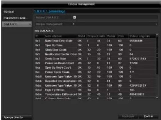
text_image
Disqor management General Parameters run SMART. 1 Smart. perimerge Active SMART Disqor management Info SMART. ID Non-attribute Shift Angle/Units Value Point Value originals 0x1 Rain Head Error Rate OK 1 44 79 63 95588406 0x2 Spin Up Time OK 3 6 100 100 0 0x4 Start/Stop Count OK 32 20 100 100 0 0x5 Reallocated Sector Count OK 33 26 93 99 64 0x7 Sink Error Rate OK 1 30 78 60 9728271543 0x9 Power on Hours Count OK 32 6 87 87 12208 0x10 Spin Up Index Count OK 13 97 100 100 0 0x11 Power Cycle Count OK 32 20 100 100 171 0x12 Unknown Type Value: 10 OK 32 99 100 100 0 0x13 Reported Uncorrectable OK 32 6 94 94 6 0x14 Unknown Type Value: 10 OK 32 6 100 99 4295432833 0x15 High Fy Write OK 3x 6 1 1 183 0x16 Temperature Difference OK 32 45 71 49 488439837 0x17 Cross Error Rate OK 52 6 100 100 3 Aporu directs Appiquee Damiertext_image
Sauvegarder Exportation 2/3: Annuleri
Remarque
'PPP over Ethernet' (protocole Point-to-Point)
'Universal Serial Bus'
natural_image
Exterior view of a black and silver electronic device with circular buttons and control knobs (no visible text or symbols)Brugerhåndbog
Version 1.0
CE
Dansk
text_image
1 2 3 4 5 6 7 8 9 0 Q W E R T Y U I O P A S D F G H J K L Z X C V B N M a Space Enter ESCIPv4 Address: 192.168.0.50
IPv4 Subnet Mask: 255.255.255.0
IPv4 Default Gateway: 192.168.0.1
Preferred DNS Server: 192.168.0.1

Henvisning
natural_image
Exterior view of a modern white building with a red logo on the facade, surrounded by greenery and trees (no visible text or symbols on the building itself)I topteksten findes menuerne
- Menu
- Playback og
• PTZ.
natural_image
Exterior view of a modern office building with 'ABUS' signage on the facade, surrounded by greenery and trees (no readable text beyond logos)text_image
00:00:11 0 1 2 3 4 5 6 7(2) (3) (4) (5) (6)

text_image
0 | 9 | 10 | 11 | 12 | 13 | 14 | 15 | 16 | (16)(7) (8) (9) (10)(11)(12)(13)(14)(15)

text_image
Indstillinger General Control PPPOE DDNS NTP Email FTP Add Videntiger indstillinger Network Active Show* SOD: Service V2 Stop Red 101 Road Community public Active Commande private Home Address Outdoor 162 Live Visiting Annend Toberge| Parameter | Indstilling |
| Aktivér SNMP | Markér afkrydsningsfeltet for at oprette en forbindelse med SNMP-software |
| SNMP Version | SNMP-systemversion |
| SNMP Port | Angiv SNMP-porten(standard: 161) |
| Read Community | Indtast „Key“ som angivet i indstillingerne i SNMP-softwaren. |
| Write Community | Indtast „Key“ som angivet i indstillingerne i SNMP-softwaren. |
| Trap Adress | Angiv SNMP-managerensIP-adresse |
| Trap Port | Angiv trap-porten(standard: 162) |
i
Henvisning
text_image
Inclalinger Program admin solution /Ending of kudbord Network Name Projection Nature MNC-Advance the Bruger Redl Text Cell 1 adults Admin 00:00:00:00:00:00 2 guest Cast 00:00:00:00:00:00 Live viewing Advanced Prager Title Tidepage
Advarsel
Notér administratorkodeordet.
text_image
C Components CYTICALS CYTICALS OF C Components C:\Program Files\N\Cement 1 C:\Documents\Supports Parameters Manager Project Board Point Controller Points ASP1 Format & Position A: B3 Self-Standard OK C:\Facial/MI - Refining - Manager - Line Interface - Component Process C:\Documents\Supports Manager Point Applications Applications Method Status Not the main components: Refining Department in Full Work 5 Live Historytext_image
Optopulse Display Kodning Udidecks indahili Frame Event scheduling Nr. Name Status Startboxmask Startboxpunk Endboxg 1 Holiday1 Deaktime 1.JanMarketing 1.JanMarketing 2 Holiday2 Deaktime 1.JanMarketing 1.JanMarketing 3 Holiday3 Deaktime 1.JanMarketing 1.JanMarketing 4 Holiday4 Deaktime 1.JanMarketing 1.JanMarketing 5 Holiday5 Deaktime 1.JanMarketing 1.JanMarketing 6 Holiday6 Deaktime 1.JanMarketing 1.JanMarketing 7 Holiday7 Deaktime 1.JanMarketing 1.JanMarketing 8 Holiday8 Deaktime 1.JanMarketing 1.JanMarketing 9 Holiday9 Deaktime 1.JanMarketing 1.JanMarketing 10 Holiday10 Deaktime 1.JanMarketing 1.JanMarketing 11 Holiday11 Deaktime 1.JanMarketing 1.JanMarketing 12 Holiday12 Deaktime 1.JanMarketing 1.JanMarketingS.M.A.R.T. står for Self-Monitoring Analysis and Reporting Technology.
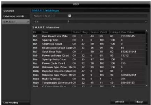
text_image
HDD Denscore Unidicate module... SMART: HDD 1 SMART Information ID Name Status Flags General Value Distinct Raw Value 0x1 Raw Read Error Rate OK 1 64 85 63 225126345 0x3 Spin Up Time OK 3 0 100 100 0 0x4 Start/Stop Count OK 22 20 100 100 0 0x5 Resilvicated Sector Count OK 33 36 99 99 65 0x7 Sock Error Rate OK 1 50 78 60 872871543 0x9 Power-on Hours Count OK 32 0 85 95 13712 0xu PSpin Up Retay Count OK 13 97 100 100 0 0xc Power Cycle Count OK 32 20 100 100 233 0xb8 Unknown Type Value_18-OK 32 99 100 100 0 0xbb Reported Unconnectable ICK 32 0 95 95 7 0xbc Unknown Type Value_18-OK 32 0 100 99 4299632833 0xbd High Fly Width OK 5a 0 1 1 204 0bde Temperature Difference ICK 22 45 71 49 589103133 0bdf Cross Error Rate OK 32 0 100 100 2 Live Visiting Amend TillageI denne undermenu vises informationer vedrørende harddiskstatus.
86444 Affing (Germany)
natural_image
Exterior view of a black and silver electronic device with circular control knobs and a red 'ABUS' logo (no readable text or symbols on main body)Instrukcja obsługi
Wersja 1.0
CE
Deutsch
These user manual contains important information for installation and operation.
This should be also noted when this product is passed on to a third party.
Therefore look after these operating instructions for future reference!
A list of contents with the corresponding page number can be found in the index.
Français
text_image
1 2 3 4 5 6 7 8 9 0 Q W E R T Y U I O P A S D F G H J K L Z X C V B N M a Space Enter ESCnatural_image
Exterior view of a modern office building with visible logo and surrounding greenery (no readable text or symbols)natural_image
Toolbar with application icons including document, folder, and search bar (no readable text)text_image
① ② Odlw catalogo data Camera Camera 01 Camera 02 Camera 03 Camera 04 ③ Mon 2012 S M T F S 1 2 3 4 5 6 7 8 9 10 11 12 13 14 15 16 17 18 19 20 21 22 23 24 25 26 27 28 29 30 31 4 B: 1 B: 2 B: 3 B: 4 B: 5 B: 6 B: 7 B: 8 B: 9 B: 10 B: 11 B: 12 B: 13 B: 14 B: 15 B: 16 B: 17 B: 18 B: 19 B: 20 B: 21 B: 22 B: 23 B: 24 B: 25 B: 26 B: 27 B: 28 B: 29 B: 30 B: 31 B: 32 B: 33 B: 34 B: 35 B: 36 B: 37 B: 38 B: 39 B: 40 B: 41 B: 42 B: 43 B: 44 B: 45 B: 46 B: 47 B: 48 B: 49 B: 50 B: 51 B: 52 B: 53 B: 54 B: 55 B: 56 B: 57 B: 58 B: 59 B: 60 B: 61 B: 62 B: 63 B: 64 B: 65 B: 66 B: 67 B: 68 B: 69 B: 70 B: 71 B: 72 B: 73 B: 74 B: 75 B: 76 B: 77 B: 78 B: 79 B: 80 B: 81 B: 82 B: 83 B: 84 B: 85 B: 86 B: 87 B: 88 B: 89 B: 90 B: 91 B: 92 B: 93 B: 94 B: 95 B: 96 B: 97 B: 98 B: 99 B: 100 Crype Zizoa#etext_image
Configuration Options Name: Zosen Size: 100 Name: admin RS232 Line: gmsf Wglns Zuynawls Live Details Work
Ostrzeżenie
text_image
C:\Users\Current Files\Current Files\Current Files\Current Files\Current Files\Current Files\Current Files\Current Files\Current Files\Current Files\Current Files\Current Files\Current Files\Current Files\Current Files\Current Files\Current Files\Current Files\Current Files\Current Files\Current Files\Current Files\Current Files\Current Files\Current Files\Current Files\Current Files\Current Files\Current Files\Current Files\Current Files\Current Files\Current Files\Current Files C:\Users\Current Files\Current Files\Current Files\Current Files\Current Files\Current Files\Current Files\Current Files\Current Files\Current Files\Current Files\Current Files\Current Files\Current Files\Current Files\Current Files\Current Files\Current Files\Current Files\Current Files\Current Files\Current Files\Current Files\Current Files\Current Files\Current Files\Current Files\Current Files\Current Files\Current Files\Current Files\Current Files C:\Documents to: Current Files C:\Documents to: Current Files C:\Documents to: Current Files C:\Documents to: Current Files C:\Documents to: Current Files C:\Documents to: Current Files C:\Documents to: Current Files C:\Documents to: Current Files C:\Documents to: Current Files C:\Documents to: Current Files C:\Documents to: Current Files C:\Documents to: Current Files C:\Documents to: Current Files C :\Documents to: Current Files C:\Documents to: Current Files C:\Documents to: Current Files C:\Documents to: Current Files C:\Documents to: Current Files C:\Documents to: Current Files C:\Documents to: Current Files C:\Documents to: Current Files C:\Documents to: Current Files C:\Documents to: Current Files C:\Documents to: Current Files C:\Documents to: Current Files C:\Documents to: C:\Users C:\Users C:\UsersS.M.A.R.T. to skrót z ang. Self-Monitoring Analysis and Reporting Technology.
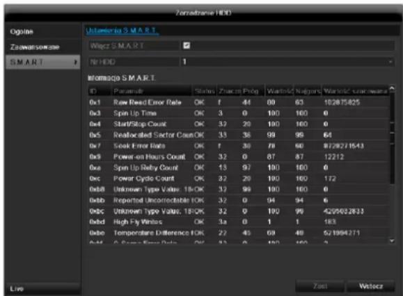
text_image
Zonadzane HDD Omega Utopoia S M A R T Zonadzane04 S M A R T > N HDD 1 Momoqga S M A R T. ID Paramate Status Znarcos Plog Wastolc Nalgans Wastolc uvar means 0x1 Raw Read Error Rate OK 1 44 69 63 102875425 0x3 Spin Up Time OK 3 0 100 100 0 0x4 Start/Stop Count OK 32 20 100 100 0 0x5 Reallocated Sector Count OK 33 38 99 99 64 0x7 Seak Error Rate OK 1 30 78 60 8728271543 0x9 Power-on Hours Count OK 32 0 87 87 12212 0xu Power On Rely Count OK 13 97 100 100 0 Dec Power Cycle Count OK 32 20 100 100 172 0x88 Unknown Type Value: 18/OK 32 99 100 100 0 0x8b Reported Uncorrectable IOK 32 0 94 94 0 0x8c Unknown Type Value: 18/OK 32 0 100 99 4295632833 0x8d High Fy Values OK 3a 0 1 1 183 0x8b Temperature Difference IOK 22 45 69 49 521994271 0x8c C Power Error Rate OK 32 0 100 100 2 Live Zasi Wistocztext_image
Recycle Recycle Edit Atom recording Recycle procedure Analog A1 A2 A3 A4 Live Wetock,Universal Serial Bus'