
Rage 258 - Receiver PEAVEY - Free user manual and instructions
Find the device manual for free Rage 258 PEAVEY in PDF.

| Product type | Electric guitar amplifier |
| Brand | Peavey |
| Model | Rage 258 (Transtube series) |
| Rated power | 25 W RMS into 8 Ω |
| Saturation power (typ.) | 25 W RMS into 8 Ω (5% THD, 1 kHz, 220 V AC) |
| Power consumption | 50 W, 50/60 Hz, 120 V / 220-240 V |
| Dimensions (H x W x D) | 37.47 cm x 41.27 cm x 34.80 cm |
| Weight | 8.07 kg |
| Input impedance (normal channel) | 1 MΩ |
| Nominal input level (normal channel) | -6 dBV (70 mV RMS) |
| Auxiliary input impedance | 100 kΩ |
| Auxiliary input nominal level | 5 V RMS, -6 dBV |
| Headphone output | Stereo, 50 mW into 8 Ω (disables internal speaker) |
| Equalization | Bass, mid, treble (passive type) |
| Main features | Two channels (Clean/Lead), Modern/Vintage/Stack selector, Pre/Post Gain, auxiliary input/direct output, headphone jack |
| Power supply | AC mains, IEC socket with ground |
| Cleaning | Use only a dry cloth |
| Safety | Do not expose to rain or moisture; do not open the unit; disconnect during thunderstorms |
| Repairability | Have all repairs done by an authorized Peavey technician |
Frequently Asked Questions - Rage 258 PEAVEY
User questions about Rage 258 PEAVEY
0 question about this device. Answer the ones you know or ask your own.
Ask a new question about this device
Download the instructions for your Receiver in PDF format for free! Find your manual Rage 258 - PEAVEY and take your electronic device back in hand. On this page are published all the documents necessary for the use of your device. Rage 258 by PEAVEY.
USER MANUAL Rage 258 PEAVEY
Intended to alert the user to the presence of uninsulated "dangerous voltage" within the product's enclosure that may be of sufficient magnitude to constitute a risk of electric shock to persons.
Intended to alert the user of the presence of important operating and maintenance (servicing) instructions in the literature accompanying the product. CAUTION: Risk of electrical shock — DO NOT OPEN!
CAUTION: To reduce the risk of electric shock, do not remove cover. No user serviceable parts inside. Refer servicing to qualified service personnel.
WARNING: To prevent electrical shock or fire hazard, this apparatus should not be exposed to rain or moisture, and objects filled with liquids, such as vases, should not be placed on this apparatus. Before using this apparatus, read the operating guide for further warnings.

Protective earthing terminal. The apparatus should be connected to a mains socket outlet with a protective earthing connection.
卫:在王亡再财青财财财财财财财财财财财财财财财财财财财财财财财财财财财财财财财财财财财财财财财财财财财财财财财财财财财财财财财财财财财财财财财财财财财财财财财财财财财

归去居于日,长吉是归去居之日。
aal aalaaal aaiy jn y gllg 111
a aee
1 2


J 1
j 1 j 1 j 1 j 1 j 1 j 1 j 1 j 1 j 1 j 1 j 1 j 1 j 1 j 1 j 1 j 1 j 1 j 1 j 1 j 1 j 1 j 1 j 1 j 1 j 1 j 1 j 1 j
IMPORTANT SAFETY INSTRUCTIONS
WARNING: When using electrical products, basic cautions should always be followed, including the following:
- Read these instructions.
- Keep these instructions.
- Heed all warnings.
- Follow all instructions.
- Do not use this apparatus near water.
- Clean only with a dry cloth.
- Do not block any of the ventilation openings. Install in accordance with manufacturer's instructions.
- Do not install near any heat sources such as radiators, heat registers, stoves or other apparatus (including amplifiers) that produce heat.
- Do not defeat the safety purpose of the polarized or grounding-type plug. A polarized plug has two blades with one wider than the other. A grounding type plug has two blades and a third grounding plug. The wide blade or third prong is provided for your safety. If the provided plug does not fit into your outlet, consult an electrician for replacement of the obsolete outlet.
- Protect the power cord from being walked on or pinched, particularly at plugs, convenience receptacles, and the point they exit from the apparatus.
- Only use attachments/accessories provided by the manufacturer.
- Use only with a cart, stand, tripod, bracket, or table specified by the manufacturer, or sold with the apparatus. When a cart is used, use caution when moving the cart/apparatus combination to avoid injury from tip-over.
- Unplug this apparatus during lightning storms or when unused for long periods of time.
Refer all servicing to qualified service personnel. Servicing is required when the apparatus has been damaged in any way, such as power-supply cord or plug is damaged, liquid has been spilled or objects have fallen into the apparatus, the apparatus has been exposed to rain or moisture, does not operate normally, or has been dropped. - Never break off the ground pin. Write for our free booklet "Shock Hazard and Grounding." Connect only to a power supply of the type marked on the unit adjacent to the power supply cord.
- If this product is to be mounted in an equipment rack, rear support should be provided.
- Note for UK only: If the colors of the wires in the mains lead of this unit do not correspond with the terminals in your plug, proceed as follows: a) The wire that is colored green and yellow must be connected to the terminal that is marked by the letter E, the earth symbol, colored green or colored green and yellow. b) The wire that is colored blue must be connected to the terminal that is marked with the letter N or the color black. c) The wire that is colored brown must be connected to the terminal that is marked with the letter L or the color red.
- This electrical apparatus should not be exposed to dripping or splashing and care should be taken not to place objects containing liquids, such as vases, upon the apparatus.
- The on/off switch in this unit does not break both sides of the primary mains. Hazardous energy can be present inside the chassis when the on/off switch is in the off position. The mains plug or appliance coupler is used as the disconnect device, the disconnect device shall remain readily operable.
- Exposure to extremely high noise levels may cause a permanent hearing loss. Individuals vary considerably in susceptibility to noise-induced hearing loss, but nearly everyone will lose some hearing if exposed to sufficiently intense noise for a sufficient time. The U.S. Government's Occupational Safety and Health Administration (OSHA) has specified the following permissible noise level exposures:
Duration Per Day In Hours Sound Level dBA, Slow Response
| 8 90 | |
| 6 92 | |
| 4 95 | |
| 3 97 | |
| 2 100 | |
| 1 1/2 102 | |
| 1 105 | |
| 1/2 | 110 |
| 1/4 or less | 115 |
According to OSHA, any exposure in excess of the above permissible limits could result in some hearing loss. Earplugs or protectors to the ear canals or over the ears must be worn when operating this amplification system in order to prevent a permanent hearing loss, if exposure is in excess of the limits as set forth above. To ensure against potentially dangerous exposure to high sound pressure levels, it is recommended that all persons exposed to equipment capable of producing high sound pressure levels such as this amplification system be protected by hearing protectors while this unit is in operation.
a) The wire that is colored green and yellow must be connected to the terminal that is marked by the letter E, the earth symbol, colored green or colored green and yellow.
b) The wire that is colored blue must be connected to the terminal that is marked with the letter N or the color black.
c) The wire that is colored brown must be connected to the terminal that is marked with the letter L or the color red.
- i
- 1
- 4.本司
- 12
- 3
- 电
- Note for UK only: If the colors of the wires in the mains lead of this unit do not correspond with the terminals in your plug, proceed as follows: a) The wire that is colored green and yellow must be connected to the terminal that is marked by the letter E, the earth symbol, colored green or colored green and yellow. b) The wire that is colored blue must be connected to the terminal that is marked with the letter N or the color black. c) The wire that is colored brown must be connected to the terminal that is marked with the letter L or the color red.
- 基于基尼的ON/OFF,S的用在等量的主的用,其可为。ON/OFF,S的用为OFF,若用以如
- 电中
曹刘寿刘君
本章中要由BA对奇性
| 8 90 |
| 6 92 |
| 4 95 |
| 3 97 |
| 2 100 |
| 1½ 102 |
| 1 105 |
| ½ 110 |
| ¼ Ⅱ Ⅲ 115 |
OSHAeHJnHJnHJnHJnHJnHJnHJnHJnHJnHJnHJnHJnHJnHJnHJnHJnHJnHJnHJnHJnHJnHJnHJnHJnHJnHJnHJnHJnHJnHJnHJnHJnHJnHJn HJnHJnHJnHJnHJnHJnHJnHJnHJnHJnHJnHJnHJnHJn HJnHJnHJnHJnHJnHJnHJn HJnHJnHJn HJn HJn HJn HJn HJn HJn HJn HJn HJn HJn HJn HJn HJn HJn HJn HJn HJn HJn HJn HJn HJn HJn HJn HJn HJn HJn HJn HJn HJn H
zagai jia jia ciayai
y
1
C. 3
3
Lolaloo 4
aill jia jao jao jao jao jao jao jao jao jao jao jao jao jao jao jao jao jao jao jao jao jao jao jao jao jao jao jao jao jao jao jao jao jao jao jao jao jao jao jao jao jao jao jao jao jao jao jao jao
6
aaii 7
8
y 9
j 10
aal 11
jepie gao / ay jai iie 1234567890123456789012345678901234567890123456789012345678901234567890123456789012345678901234567890123456789
A 13
14
e 15
17
N 1
jL jll jll jll l
18
y 19
20
| 8 90 |
| 6 92 |
| 4 95 |
| 3 97 |
| 2 100 |
| 2/1 1102 |
| 1 105 |
| 2/1 110 |
4y 1
J 1 1 1 1 1 1 1 1 1 1 1 1 1 1 1 1 1 1 1 1 1 1 1 1 1 1 1 1 1 1 1 1 1 1 1 1 1
115
Logo referenced in Directive 2002/96/EC Annex IV(OJ(L)37/38,13.02.03 and defined in EN 50419:2005
The bar is the symbol for marking of new waste and is applied only to equipment manufactured after 13 August 2005
Correct Disposal of this product. This marking indicates that this product should not be disposed with other house hold wastes throughout the EU. To prevent possible harm to the environment or human health from uncontrolled waste disposal, recycle it responsibly to promote the sustainable reuse of material resources. To return your used device, please use the return and collection systems, or contact the retailer where the product was purchased. They can take this product for environmental safe recycling.

FCC Compliancy Statement
This device complies with Part 15 of the FCC rules. Operation is subject to the following two conditions: (1) this device may not cause harmful interference, and (2) this device must accept any interference received, that may cause undesired operation.
Warning: Changes or modifications to the equipment not approved by Peavey Electronics Corp. can void the user's authority to use the equipment.
Note - This equipment has been tested and found to comply with the limits for a Class B digital device, pursuant to Part 15 of the FCC Rules. These limits are designed to provide reasonable protection against harmful interference in a residential installation. This equipment generates, uses and can radiate radio frequency energy and, if not installed and used in accordance with the instructions, may cause harmful interference to radio communications. However, there is no guarantee that interference will not occur in a particular installation. If this equipment does cause harmful interference to radio or television reception, which can be determined by turning the equipment off and on, the user is encouraged to try and correct the interference by one or more of the following measures.
- Reorient or relocate the receiving antenna.
- Increase the separation between the equipment and receiver.
- Connect the equipment into an outlet on a circuit different from that to which the receiver is connected.
- Consult the dealer or an experienced radio/TV technician for help.

ENGLISH
Rage 258® - Transtube Series - Guitar Amplifier

Before you begin to play through your amplifier, it is very important to ensure the product has the proper AC line voltage supplied. You can find the proper voltage for your amp printed next to the IEC line (power) cord on the rear panel of the unit. Each product feature is numbered. Refer to the front panel diagram in this manual to locate the particular features next to their number.
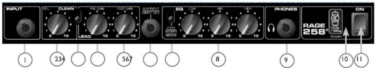
INPUT
This Input jack will accept signals from all types of guitar pickups. Be sure to use a high quality shielded instrument cable to connect the guitar to the amplifier.
VOLUME
Controls the volume level of the Clean channel and is not affected by the Lead Pre or Post Gain controls.
CHANNEL SELECT SWITCH
Allows selection of the Lead or Clean channel. The "down" position of the switch selects the Lead channel and the "up" position selects the Clean channel.
PRE GAIN
Controls the input volume level of the Lead channel. The Pre Gain can be used to control the distortion level in the Lead channel. To obtain more distortion simply increase the Pre Gain and set the Post Gain (5) to the desired volume level.
POST GAIN
Controls the overall volume level of the Lead channel. The final level adjustment should be made after the desired sound has been achieved.
AUX INPUT/DIRECT OUTPUT
The AUX INPUT can be used to route the headphone out signal of a CD player, tape player, etc. into your Rage amplifier. Connect the CD or tape headphone output using a shielded cable to the AUX INPUT jack. This jack can also serve as a low-level direct out for recording devices. This signal is mixed with the guitar signal but is not affected by the EQ.
MODERN/VINTAGE/STACK SWITCH
This switch allows you to instantly change the voicing to reflect the tones of modern and vintage amplifiers. The "MODERN" position maintains a warm, standard voicing. The "VINTAGE" position changes the overall function of the EQ and adds a hint of brightness to emulate some classic amp designs. The "Stack" setting provides a preset EQ curve to mimic the tone of a larger amp. Experiment with this switch, along with the EQ (8) adjustments, to capture your desired tone. You may refer to the Recommended Settings on page 8 for some creative starting points.

LOW, MID AND HIGH EQ
Passive tone controls that regulate the low, mid and high frequencies, respectively.
HEADPHONE JACK
This stereo jack allows signal to flow to both sides of any stereo headset. A monaural headset may be used, but it is not recommended.
POWERLED
Illuminates when power has been supplied to the unit.
POWER SWITCH
Press the switch to the "ON" position to apply power to the unit. The POWER LED (10) will illuminate to indicate power has been supplied to the unit.

12
AC POWER CORD (REAR PANEL)
This line cord provides the AC power to the unit. Connect the line cord to a properly grounded AC supply. Damage to the equipment may occur if improper line voltage is used. (See voltage marking on unit.) Never remove or cut the ground pin of the line cord plug.
NOTE: FOR UK ONLY
As the colors of the wires in the mains lead of this apparatus may not correspond with the colored markings identifying the terminals in your plug, proceed as follows: (1) The wire which is colored green and yellow must be connected to the terminal which is marked by the letter E, or by the earth symbol, or colored green or green and yellow. (2) The wire which is colored blue must be connected to the terminal which is marked with the letter N, or the color black. (3) The wire which is colored brown must be connected to the terminal which is marked with the letter L or color red.
Specifications
POWER AMP SECTION
Rated Power:
25 W(rms) into 8 Ω
Power @ Clipping (Typically):
(5% THD, 1 kHz, 120 V AC line)
25 W RMS into 8Ω
Rated Consumption:
50W, 50/60 Hz, 120V/220-240V
PRE AMP SECTION
The following specs are
measured @ 2 kHz with the
controls preset as follow
Channel Select Normal (OUT)
Low and High @ 10
Mid @ o
Pre Gain and Post Gain @ 10
Preamp Input (Normal Channel):
Impedance: High Z, 1 M Ω
Nominal Input Level: -6 dBV
70 mV RMS
Aux Input:
Input Impedance: 100 k Ω
Nominal Input Level:.5V RMS,
-6 dBV
(Stereo jack designed for use with stereo headphone output on CD/Tape Player)
Headphone Output:
Load Impedance: 8 Ω
Nominal Power Output:
50 mW into 8 Ω
(Stereo jack, monaural signal disconnects internal speaker when phone plug is inserted.)
Equalization:
Special low, mid, and high passive type EQ
As the colors of the wires in the mains lead of this apparatus may not correspond with the colored markings identifying the terminals in your plug, proceed as follows: (1) The wire which is colored green and yellow must be connected to the terminal which is marked by the letter E, or by the earth symbol, or colored green or green and yellow. (2) The wire which is colored blue must be connected to the terminal which is marked with the letter N, or the color black. (3) The wire which is colored brown must be connected to the terminal which is marked with the letter L or color red.
Spezifikationen
VERSTÄRKER
Leistung:
25 W (RMS) in 8 Ω
As the colors of the wires in the mains lead of this apparatus may not correspond with the colored markings identifying the terminals in your plug, proceed as follows: (1) The wire which is colored green and yellow must be connected to the terminal which is marked by the letter E, or by the earth symbol, or colored green or green and yellow. The wire which is colored blue must be connected to the terminal which is marked with the letter N, or the color black. (3) The wire which is colored brown must be connected to the terminal which is marked with the letter L or color red.
Specifications
SECTION AMPLIFICATEUR DE PUISSANCE
As the colors of the wires in the mains lead of this apparatus may not correspond with the colored markings identifying the terminals in your plug, proceed as follows: (1) The wire which is colored green and yellow must be connected to the terminal which is marked by the letter E, or by the earth symbol, or colored green or green and yellow. The wire which is colored blue must be connected to the terminal which is marked with the letter N, or the color black. (3) The wire which is colored brown must be connected to the terminal which is marked with the letter L or color red.
Especificaciones
As the colors of the wires in the mains lead of this apparatus may not correspond with the colored markings identifying the terminals in your plug, proceed as follows: (1) The wire which is colored green and yellow must be connected to the terminal which is marked by the letter E, or by the earth symbol, or colored green or green and yellow. (2) The wire which is colored blue must be connected to the terminal which is marked with the letter N, or the color black. (3) The wire which is colored brown must be connected to the terminal which is marked with the letter L or color red.
仕樣
電源アング部
定格電力:
8Ωlc25W(rms)
電力@ケリットンダ(標準):
Rage 258® - Transtube Series - Guitar Amplifier
(5% THD, 1kHz, 120VAC)
Consumo Nominal: 50W, 50/60
Hz, 120V/220-240V
SECAO PRE AMP (Pre
Amplificador)
Channel Select Normal (OUT)
Graves e Agudos: 10 / Mid: o / Pré e
Post Gain: 10
Entrada Pre Amp (Canal Normal):
(37,47cm x 41,27cm x 34,80cm)
Peso:
8,07 Kgs (17,8 lbs)
Warranty registration and information for U.S. customers available online at
www.peavey.com/warranty or use the QR tag below

Features and specifications subject to change without notice.
Peavey Electronics Corporation 5022 Hartley Peavey Drive Meridian, MS 39305 (601) 483-5365 FAX (601) 486-1278

- IMPORTANT SAFETY INSTRUCTIONS
- zagai jia jia ciayai
- FCC Compliancy Statement
- ENGLISH
- Rage 258® - Transtube Series - Guitar Amplifier
- INPUT
- VOLUME
- CHANNEL SELECT SWITCH
- PRE GAIN
- POST GAIN
- AUX INPUT/DIRECT OUTPUT
- MODERN/VINTAGE/STACK SWITCH
- LOW, MID AND HIGH EQ
- HEADPHONE JACK
- POWERLED
- POWER SWITCH
- AC POWER CORD (REAR PANEL)
- NOTE: FOR UK ONLY
- Specifications
- POWER AMP SECTION
- Rated Power:
- Power @ Clipping (Typically):
- Rated Consumption:
- PRE AMP SECTION
- The following specs are
- measured @ 2 kHz with the
- controls preset as follow
- Preamp Input (Normal Channel):
- Aux Input:
- Headphone Output:
- Equalization:
- Spezifikationen
- VERSTÄRKER
- SECTION AMPLIFICATEUR DE PUISSANCE
- Especificaciones
- 仕樣
- 電源アング部
- 定格電力:
Brand : PEAVEY
Model : Rage 258
Category : Receiver