
RM 8405 - Fridge DOMETIC - Free user manual and instructions
Find the device manual for free RM 8405 DOMETIC in PDF.

| Product type | Absorption refrigerator for leisure vehicles (caravans, motorhomes) |
| Brand | Dometic |
| Model | RM 8405 |
| Dimensions (H x W x D) | 821 x 486 x 568 mm |
| Net weight | 27 kg |
| Total gross capacity | 90 liters (95 liters with door removed) |
| Freezer compartment capacity | 8 liters |
| Energy sources | 230 V AC, 12 V DC, liquefied gas (propane/butane) |
| Power consumption (230 V) | Approximately 2.4 kWh/24h |
| Gas consumption | Approximately 270 g/24h |
| Connection power (230 V / 12 V) | 135 W / 130 W |
| Ignition type | Automatic (AES) with automatic energy selection |
| Main functions | Manual mode (230V, 12V, gas), automatic mode (AES), temperature setting, removable freezer compartment, interior lighting, door lock, door open signal |
| Climate class | SN (ambient temperature from +10°C to +32°C) |
| Refrigerant | Ammonia (NH3), anti-corrosion agent: sodium chromate |
| Routine maintenance | Interior cleaning with soft cloth, warm water and mild detergent; defrost when frost layer reaches 3 mm |
| Gas maintenance | Inspection of gas installation every 2 years; burner cleaning at least once a year (2 to 3 times for liquefied petroleum gas) |
| Safety | Never open the refrigeration unit (high pressure); prohibition of using gas at service stations; defrost without force or heat source; automatic gas shut-off if flame goes out (manual models); door lock mandatory when traveling |
| Spare parts and repairability | Parts available through Dometic after-sales service; repairs reserved for authorized professional; rating plate inside the refrigerator |
| Warranty | Compliant with directive 44/1999/EC; warranty void in case of non-compliance with instructions or improper use |
| General information | 323-page instruction manual available in multiple languages; the refrigerator must be installed horizontally for optimal operation |
Frequently Asked Questions - RM 8405 DOMETIC
User questions about RM 8405 DOMETIC
0 question about this device. Answer the ones you know or ask your own.
Ask a new question about this device
Download the instructions for your Fridge in PDF format for free! Find your manual RM 8405 - DOMETIC and take your electronic device back in hand. On this page are published all the documents necessary for the use of your device. RM 8405 by DOMETIC.
USER MANUAL RM 8405 DOMETIC
natural_image
Line drawing of a rectangular kitchen appliance with control panel and door (no text or symbols)RM 8400 RM 8401 RM 8405
RM 8500 RM 8501 RM 8505
RM 8550 RM 8551 RM 8555
RMS 8400 RMS 8401 RMS 8405
RMS 8460 RMS 8461 RMS 8465
RMS 8500 RMS 8501 RMS 8505
RMS 8550 RMS 8551 RMS 8555
RML 8550 RML 8551 RML 8555
RMSL 8500 RMSL 8501 RMSL 8505
ENGLISH
Dometic Group is a customer-driven, world-leading provider of leisure products for the RV, automotive, truck and marine markets. We supply the industry and aftermarket with a complete range of air conditioners, refrigerators, awnings, cookers, sanitation systems, lighting, mobile power equipment, comfort and safety solutions, windows, doors and other equipment that make life more comfortable away from home. Dometic Group supplies a wide range of workshop equipment for service and maintenance of built-in air conditioners. Dometic Group also provides specially designed refrigerators for hotel rooms, offices, wine storage and transport and storage of medical products. Our products are sold in almost 100 countries and are produced mainly in wholly-owned production facilities around the world.
SVENSKA
natural_image
Line drawing of a white refrigerator with control panel and door (no text or symbols)Type C40 / 110
CE
E _1
10 R - 047358
N4
MBA 12/2014
DE

Für Ihre Sicherheit

WARNUNG!
DECLARATION OF CONFORMITY
according to
Low Voltage Directive 73/23/EEC and
the Amendment to LVD 2006/95/EC
EMC Directive 2004/108/EC
Automotive Directive 72/245/EEC and
the Amendment 95/54/EC, 2009/19/EC
Gas Appliance Directive 2009/142/EC
End-of-Life Vehicle Directive 2000/53/EC
RoHS Directive 2002/95/EC
Type of equipment
Brand Name
Type family
Manufacturer's (Factory)
name
address
telephone no
telefax no
Absorption Refrigerator
DOMETIC
C 40/110
DOMETIC GmbH
The following harmonized standards or technical specifications (designations) which comply with good engineering practice in safety matters in force within the EEA have been practiced:
EN 60335-1;02. (IEC 60335-1; 4 ed., Am. 1, Am. 2),
EN 60335-2-24:03 (IEC 60335-2-24; 6 ed., Am. 1, Am. 2)
EN 61000-3-2;00, A1, A2, A14 EN 61000-3-3;95, A1,
EN 55014-1:07. A1. A2 EN 55014-2:01. A1
The equipment conforms completely with the above stated harmonized standards or technical specifications.
By signing this document, the undersigned declares as manufacturer, or the manufacturer's authorized representative established within the EEA, that the equipment in question complices with the requirements stated above.
Date
2012.01.04

Position
General Manager

natural_image
Technical line drawing of a refrigerant appliance with no visible text or symbols
text_image
RM 8xxx T B H
natural_image
Line drawing of a RML 8xxx battery unit (no text or symbols on the diagram itself)Abb. 3
Abb. 4
text_image
Diagram showing four labeled circular components with numbered annotations, likely illustrating a control or measurement setup.Abb. 7
text_image
Diagram showing a hand pressing down on a circular dial with labeled buttons 2, 3, and 4, alongside a droplet symbol.Abb. 14
text_image
Domestic 1natural_image
Diagram showing a kitchen sink with a water drop and two circular fixtures on a tray (no text or symbols)Abb. 24
natural_image
Interior view of a room with a curved door and wall-mounted window (no text or symbols visible)Abb. 25
natural_image
Diagram of a mechanical component with an arrow indicating direction (no text or symbols present)Fixieren
natural_image
Illustration of a mechanical device with a handle and internal components (no text or symbols)Abb. 26
Abb. 27
natural_image
Diagram of a mechanical device with a downward arrow indicating force or movement (no text or symbols present)Lösen
Abb. 28

natural_image
Technical illustration of a mechanical component with a handle and mounting bracket (no text or symbols)Abb. 29
4.11 Beleuchtung
natural_image
Mechanical assembly diagram showing a piston-like component with circular motion indicators (no text or symbols)Abb. 30

natural_image
Diagram of a metal grid structure with an arrow pointing to it, no text or symbols presentAbb. 31
text_image
Diagram showing a mechanical component with labeled parts and directional arrow, likely illustrating a process or assembly.Abb. 34
natural_image
Illustration of a hand using a pipette to process a 3x4 grid-patterned tray (no text or symbols visible)Abb. 38

natural_image
3D illustration of a rectangular block with a grid pattern on top, placed on a flat surface (no text or symbols)Abb. 39
natural_image
Mechanical component with a black arrow pointing to a specific part (no text or symbols visible)Abb. 42

natural_image
Pure mechanical assembly diagram showing a piston-like component with a black arrow indicating direction (no text or symbols)Abb. 43
natural_image
Technical diagram of a mechanical assembly with arrows indicating motion or force direction (no text or symbols)Abb. 47
text_image
2 16Abb. 48 Abb. 49
natural_image
Diagram of a door frame with two arrows pointing to the right side of the door (no text or symbols present)
natural_image
Technical diagram showing a corner joint with two downward arrows indicating force or direction (no text or symbols present)Abb. 50
Operating instructions
Absorption Refrigerator for Recreation Vehicles
RM 8400 RM 8401 RM 8405 RM 8500 RM 8501 RM 8505 RM 8550 RM 8551 RM 8555
RMS 8400 RMS 8401 RMS 8405 RMS 8460 RMS 8461 RMS 8465 RMS 8500 RMS 8501
RMS 8505 RMS 8550 RMS 8551 RMS 8555 RML 8550 RML 8551 RML 8555 RMSL 8500
RMSL 8501 RMSL 8505
Record for future reference:
Model number ....
Product number ....
Serial number ....
natural_image
Line drawing of a white refrigerator with control panel and door (no text or symbols)Type C40 / 110
CE
E _1
10 R - 047358
N4
MBA 12/2014
EN
For your safety

WARNING!
This appliance is not intended for use by persons (including children) with reduced physical, sensory or mental capabilities, or lack of experience and knowledge, unless they are supervised or have been given instruction concerning use of the appliance by a person responsible for their safety. Children should be supervised to ensure that they do not play with the appliance. Cleaning and user maintenance shall not be made by children.

DANGER!

Never use an unshielded flame to check gas bearing parts and pipes for leakage! There is a danger of fire or explosion.

WARNING!
Operating the appliance with gas is not permitted
■ at petrol stations
■ on ferry boats, and on board motor rail trains
■while transporting the caravan/motor-home by a transporter or breakdown vehicle.
There is the danger of fire!
Switch off the appliance.
It is imperative that the operating pressure of the pressure reducer on the gas system corresponds to the data specified on the rating plate of the refrigerator. If the values are different, the appliance can be damaged and a dangerous situation can be produced.
The refrigerator is not suitable for the proper storage of medication. Please observe in addition the instructions in the medication package inserts.
Leave the living area immediately if you smell ammonia. Switch off the appliance before leaving.
Never open the absorber cooling unit! It is under high pressure.
There is a danger of injury!
Work on gas equipment, exhaust system and electrical facilities must be carried out by authorised personnel only. Substantial damage to property and/or injury to persons can arise through unprofessional procedures.

WARNING!
Protect children:
When disposing of the refrigerator, detach all refrigerator doors and leave the storage racks in the refrigerator. In this way inadvertent entrappment and suffocation is prevented.
Making ice cubes:
Only use drinking water!

CAUTION!
The refrigerator unit becomes very hot during operation. Protect yourself against contact with high temperature parts when ventilation grilles are removed.
If the connection cable is damaged it must be replaced by the Customer Service at Dometic, or by respectively qualified personnel, in order to prevent any hazards.
As a basic rule, shut and lock the refrigerator before you start your journey!
CAUTION!
Changing the batteries :
■Remove discharged batteries.
■Replace the batteries completely.
■ Do not mix different types of batteries.
- Observe the correct polarity!
■ Do not connect non-rechargeable batteries to a charger.
■Remove rechargeable batteries from the battery compartment before charging.
■Avoid short circuits on the contacts in the battery compartment!
■Remove the batteries from the battery compartment if the refrigerator will not be used for a long time.
Operation with 230V\~ :
This option should only be selected where the supply voltage of the connection for power supply corresponds to the value specified on the data plate. Any difference in values may result in damage the appliance.
Defrosting:
The layer of ice must never be removed forcibly, nor may defrosting be accelerated using a heat source!
Vehicle cleaning:
Do not use any water high-pressure cleaner for vehicle cleaning in the area of the ventilation grille.
Table of contents
1.0 General 6
1.1 Introduction 6
1.2 Guide to these operating instructions 6
1.3 Copyright protection 6
1.4 Explanation of symbols used in this manual 6
1.5 Warranty 7
1.6 Limitation of liability 7
1.7 Customer services 7
1.8 Spare parts 7
1.9 Environmental notices 8
1.9.1 Disposal 8
1.9.2 Energy-saving-tips 8
1.10 Declaration of conformity 8
2.0 Safety instructions 9
2.1 Application according to regulations 9
2.2 User's responsibility 9
2.3 Protection of children when disposing of the equipment 9
2.4 Working upon and checking the refrigerator 9
2.5 Information on coolant 10
2.6 Appliances with electronics (MES/AES) 10
2.7 Operating the refrigerator with gas 11
2.8 Safety instructions when storing foodstuffs 11
3.0 Description of model 12
3.1 Model identification 12
3.2 Refrigerator rating plate 12
3.3 Technical data 13
3.4 Description of refrigerator 14
4.0 Refrigerator operation 15
4.1 Cleaning 15
4.2 Maintenance 15
4.3 Electrical operation 15
4.4 Gas operation (liquid gas) 16
4.5 Explanation of operating controls 16
4.6 RM 8xx0 models 18
4.6.1 Electrical operation 18
4.6.2 Gas operation 18
4.6.3 Setting of cooling compartment temperature 16
4.7 RM 8xx1models 19
4.7.1 Electrical operation 19
4.7.2 Gas operation 19
4.7.3 Setting of cooling compartment temperature 19
4.8 RM 8xx5 models 19
4.8.1 Manual operation 19
4.8.2 Automatic operation 20
4.8.3 Setting of cooling compartment temperature 20
4.8.4 Refuelling while in AES mode operation 20
4.8.5 Additional features (MES and AES) 20
4.9 Self-contained gas operation and optional battery compartment ..... 21
4.9.1 Inserting / changing the batteries 21
4.10 Door locking 22
4.10.1 Fastening and releasing the door lock hook when parking the vehicle 22
4.11 Lighting 22
4.12 Positioning the storage racks 22
4.13 Removable freezer compartment 23
4.14 Exchange of the igniter's battery 23
4.15 Operation during low outside temperatures 23
4.16 Storing food and making ice cubes 24
4.16.1 Storing products in the cooling compartment 24
4.16.2 Storing products in the freezer compartment 24
4.16.3 Refrigerator compartments 24
4.16.4 Making ice cubes 25
4.17 Shutting off the refrigerator 25
4.18 Defrosting 25
4.19 Changing the decor panel 26
4.20 Troubleshooting 27
4.21 Information on failure display and trouble-shooting 28
4.21.1 Status indicators 28
Dometic
Dometic GmbH
You have made an excellent choice in selecting the Dometic Absorption Refrigerator. We are sure that you will be satisfied with your new refrigerator in all respects. The refrigerator, which works silently, meets high quality standards and guarantees the efficient utilisation of resources and energy throughout its entire life cycle, during manufacture, in use and when being disposed of.
1.2 Guide to these operating instructions
Before you start using the refrigerator, please read the operating instructions carefully.
These instructions provide you with the necessary guidance for the proper use of your refrigerator. Observe in particular the safety instructions. Observation of the instructions and handling recommendations is important for dealing with the refrigerator safely and for protecting you from injury and the refrigerator from damage. You must understand what you have read before you carry out a task.
Keep these instructions in a safe place close to the refrigerator so they may be referred to at any time.
1.3 Copyright protection
The information, texts and illustrations in these instructions are copyright protected and are subject to industrial property rights.
No part of these instructions may be reproduced, copied or utilised in any other way without written authorisation by Dometic GmbH, Siegen.
1.4 Explanation of symbols used in this manual
Warning notices
Warning notices are identified by symbols. A supplementary text gives you an explanation of the degree of danger.
Observe these warning notices rigorously. You will thus protect yourself and other people from injury, and the appliance from damage.

DANGER!
DANGER indicates an imminent hazardous situation which, if not avoided, could result in death or serious injury.

WARNING!
WARNING indicates a potentially hazardous situation which, if not avoided, could result in death or serious injury

CAUTION!
WARNING indicates a potentially hazardous situation which, if not avoided, could result in death or serious injury
CAUTION!
CAUTION (used without the safety alert symbol) indicates a potentially hazardous situation which, if not avoided, may result in damage to the appliance.
Information

INFORMATION gives you supplementary and useful guidance when dealing with your refrigerator.
Environmental Tips

ENVIRONMENTAL TIPS gives you useful guidance for saving energy and disposal of the appliance.
1.5 Warranty
Warranty arrangements are in accordance with EC Directive 44/1999/CE and the normal conditions applicable for the country concerned. Please contact your dealer in the event of a warranty claim.
Any damage due to improper use is not covered by the warranty. The warranty does not cover any modifications to the appliance or the use of non-original Dometic parts. The warranty does not apply if the installation and operating instructions are not adhered to and no liability shall be entertained.
1.6 Limitation of liability
All information and guidance in these operating instructions were prepared after taking into consideration the applicable standards and regulations as well as the current state of the art. Dometic reserves the right to make changes at any time which are deemed to be in the interest of improving the product and safety.
Dometic will assume no liability for damage in the case of :
■non-observation of the operating instructions
■application not in accordance with the regulations or provisions
■ use of non-original spare parts
■modifications and interferences to the appliance
1.7 Customer services
Find your authorised customer service centre by calling the phone number indicated in the EuroService Network book, EuroService Network - which accompanies every refrigerator. You can also obtain the address information of the nearest customer service from www.dometic.com. When contacting Dometic Customer Services, please state the model, product number and serial number together with the MLC code, if applicable. You will find this information on the rating plate inside the refrigerator. We recommend that you note this data in the field provided on the front page of this operation manual.
1.8 Spare parts
Parts can be ordered throughout Europe from our customer services.
Always give the model and product number when you contact the customer service! You will find this information on the rating plate inside the refrigerator.
1.9 Environmental notices

Ammonia (a natural compound of hydrogen and nitrogen) is used in the cooling unit as a coolant. Non-ozone-hazardous cyclopentane is used as a propellant for manufacturing PU foam insulation.
1.9.1 Disposal
In order to ensure that the recyclable packaging materials are re-used, they should be sent to the customary local collection system. The appliance should be transferred to a suitable waste disposal company that will ensure re-use of the recyclable components and proper disposal of the rest. For eco-friendly draining of the coolant from all absorber refrigeration units, a suitable disposal plant should be used.

Do not dispose of batteries in domestic waste. Take your used batteries to your dealer or a collection point.
1.9.2 Energy-saving-tips
At an average ambient temperature of 25^ C, it is sufficient to operate the refrigerator at middle thermostat setting.
■Where possible, always store precooled products.
■ Do not expose the refrigerator to direct sunlight or any other heat source (e.g. heater).
■ Ensure that air circulation of the refrigeration unit is not obstructed.
- Arrange the shelves evenly in the refrigerator (in the cooling compartment) in order to achieve the most efficient use of energy.
■ Do not overfill the storage grids and compartments to prevent obstructing the internal air circulation.
■Maintain a clearance of approx. 10 mm between chilled products and post-evaporator ("cooling fins").
■Defrosting at regular intervals saves energy (see section Defrosting).
■Open the refrigerator door only for a short period of time when removing products.
■Run the refrigerator for about 12 hours before filling it.
1.10 Declaration of conformity
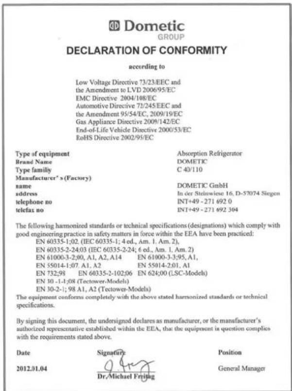
text_image
Dometic GROUP DECLARATION OF CONFORMITY according to Low Voltage Directive 73/23/EEC and the Amendment to LVD 2006/95/EC EMC Directive 2004/108/EC Automotive Directive 72/245/EEC and the Amendment 95/54/EC, 2009/19/EC Gas Appliance Directive 2009/142/EC End-of-Life Vehicle Directive 2000/53/EC RoHS Directive 2002/95/EC Type of equipment Absorption Refrigerator Brand Name DOMETIC Type family C 40/110 Manufacturer's (Factory) name DOMETIC GmbH address In der Steinwiese 16, D-57074 Siegen telephone no INT+49 -271 692 0 telefax no INT+49 -271 692 304 The following harmonized standards or technical specifications (designations) which comply with good engineering practice in safety matters in force within the EEA have been practiced: EN 60335-1:02. (IEC 60335-1; 4 ed., Am. 1. Am. 2), EN 60335-2-24:03 (IEC 60335-2-24; 6 ed., Am. 1. Am. 2) EN 61000-3-2:00, A1, A2, A14 EN 61000-3-3:95, A1, EN 55014-1:07, A1, A2 EN 55014-2:01, A1 EN 732:98 EN 60335-2-102:06 EN 624:00 (LSC-Models) EN 10 -1-1:08 (Tectower-Models) EN 10-2-1; 98 A1, A2 (Tectower-Models) The equipment conforms completely with the above stated harmonized standards or technical specifications. By signing this document, the undersigned declares as manufacturer, or the manufacturer's authorized representative established within the EEA, that the equipment is question complies with the requirements stated above. Date Signature Position 2012.01.04 Dr.Michael Freitag General Manager
The current Declaration of Conformity can also be requested directly from Dometic GmbH, Siegen.
2.0 Safety instructions
2.1 Application according to regulations
This refrigerator is designed for installation in recreation vehicles such as caravans or motorhomes. The appliance has been type-approval tested for this application in accordance with the EC Gas Directive.
The refrigerator is to be used solely for storing foodstuffs.

WARNING!
The refrigerator is not suitable for the proper storage of medication. Please observe in addition the instructions in the medication package inserts.
2.2 User's responsibility
Anyone operating the refrigerator must be familiar with the safe handling and understand the advice in these operating instructions.
This appliance is not intended for use by persons (including children) with reduced physical, sensory or mental capabilities, or lack of experience and knowledge, unless they are supervised or have been given instruction concerning use of the appliance by a person responsible for their safety. Children should be supervised to ensure that they do not play with the appliance. Cleaning and user maintenance shall not be made by children.
[EN 60335-2-24, 7.12]
2.3 Protection of children when disposing of the equipment

WARNING!
When disposing of the refrigerator, detach all refrigerator doors and leave the storage racks in the refrigerator. In this way inadvertent entrapment and suffocation is prevented.
2.4 Working upon and checking the refrigerator

WARNING!
Work on gas equipment, exhaust system and electrical facilities must be carried out by authorised personnel only. Substantial damage to property and/or injury to persons can arise through unprofessional procedures.

DANGER!

Never use an unshielded flame to check gas bearing parts and pipes for leakage!
There is a danger of fire or explosion.

WARNING!
Never open the absorber cooling unit! It is under high pressure.
There is a danger of injury!
2.5 Information on coolant
Ammonia is used as a coolant.
This is a natural compound also used in household cleaning agents (1 litre of Salmiak cleaner contains up to 200g of ammonia - about twice as much as is used in the refrigerator). Sodium chromate is used for corrosion protection (1.8% by weight of the solvent).
If you smell ammonia:

WARNING!
■Switch off the appliance.
■ Open all windows and doors to ensure ventilation.
Leave the living area.
■Inform the authorised Dometic customer service.
2.6 Appliances with electronics (MES/AES)
Car manufacturers often use a so-called battery management system, which provides the caravan with constant voltage in trailer mode.
If the car and trailer remain parked for more than 30 minutes with the engine switched off, the battery management system automatically switches off the permanent positive supply to the caravan (to prevent the battery from discharging). Fridges with control electronics (MES/AES) are then inoperative.
Check whether your drawing vehicle is equipped with a battery management system.
A permanent 12V power supply must be guaranteed for operation of the MES/AES fridges.
2.7 Operating the refrigerator with gas
It is imperative that the operating pressure of the pressure reducer on the gas system corresponds to the data specified on the rating plate of the refrigerator. Compare the operating pressure of the rating plate with the data specified on the pressure reducing valve of the liquid gas cylinder.

Dometic refrigerators are equipped for a connection pressure of 30 mbar. For connection to a 50 mbar gas system, use Truma VDR 50/30 medium pressure controller.

WARNING!
Operating the appliance with gas is not permitted
■ at petrol stations
■ on ferry boats and on board motor rail trains
■ while transporting the caravan/motor-home by a transporter or breakdown vehicle.
There is the danger of fire!
Switch off the appliance.
If you smell gas:
■Open all windows and leave the room.
■Do not operate any electrical equipment and prevent the use of naked flames.
■Do not operate any electrical equipment and prevent the use of naked flames.
■Contact authorised specialist personnel* for advice.
* authorised specialist personnel
Authorised specialist personnel are accredited experts who are able, by virtue of their training and knowledge, to vouch that the inspection and repair work has been carried out properly.
2.8 Safety instructions when storing foodstuffs
No refrigerator of any kind can improve the quality of the food; refrigerators can only maintain the food's quality for a short duration as from the time of storing it.
Please observe the following particular conditions for storing food in a refrigerator that is built into a vehicle:
■A change in the climatic conditions such as temperature fluctuations
■High temperatures inside the vehicle when it is closed and parked in direct sunlight (temperatures are possible up to 50°C)
■A refrigerator built in behind a window and exposed to direct sunlight
■Storing the products too soon, i.e. shortly after starting up the appliance for use
■Use of the refrigerator during travel with the power supply of 12V DC
■ Fluctuations in the power supply at the parking place when using the energy type 230V AC (mains voltage).
line
| V~ | C_interior | | ---- | ---------- | | 230 | 5 | | 210 | 10 | | 190 | 15 |schematic
Under these particular conditions the refrigerator cannot guarantee reaching the temperature needed for perishables.
Perishables include all products with a stipulated use-by date and a minimum storage temperature of +4°C or less, especially for meat, poultry, fish, sausages, pre-packed foods.
Storing foodstuffs:
■Pack raw and cooked foods separately
(e.g. in containers, aluminium foil, etc.).
■ Only remove the outside packaging of single packs if all the necessary information, e.g. the use-by date, can also be read on the single packs.
■Please observe the instructions and information regarding the use-by date on the outside packaging of the food.
■Do not leave cooled goods outside the refrigerator for too long.
■Place the foods with the next use-by date at the front, accordingly.
■Pack away any left-over food and eat at the first opportunity.
■Wash your hands before and after handling any food.
■ Regularly clean the inside of the refrigerator.
Please observe section Cleaning of this instruction.
i
The cooling unit's performance is influenced by ambient temperatures. Please select the medium setting for ambient temperatures between +15°C and +25°C (refer to Setting of cooling compartment temperature). The unit operates within its optimum performance range. Dometic refrigerators work according to the absorption principle. For physical reasons, an absorption system responds slowly to changes made by the thermostat controller, by loss of cooling energy through opening the door or during storing food. The devices meet the cooling performance requirements of the Climatic Class SN acc. to EN/ISO 7371 in the temperature range of +10°C to +32°C ambient temperature.
Cold air can restrict the performance of the unit. Install the winter covers if you discover any loss of cooling performance when outdoor temperatures are low (see Operation during low outside temperatures). For ambient temperatures exceeding +32°C for a longer period of time, it is recommended installing Dometic additional fan (item no. 241 2985 - 01).
3.0 Description of model
3.1 Model identification
Example :
flowchart
graph TD
    A["RM (S)(L) 8 4 0 0"] --> B["Depth: 0 = 568mm, 5 = +55mm, 6 = +65mm"]
    B --> C["4 = Width 486mm, 5 = Width 523mm"]
    C --> D["Model range "8""]
    D --> E["Large"]
    E --> F["Stepped cabinet"]
    F --> G["Refrigerator Mobile / Mobile Absorption Refrigerator"]
0
manual energy selection + manual ignition (battery igniter)
1
manual energy selection, automatic ignition (MES)
5
automatic energy selection, automatic ignition (AES)
3.2 Refrigerator rating plate
The rating plate is to be found on the inside of the refrigerator. It contains all important details of the refrigerator. You can read off from this the model identification, the product number and the serial number. You will need these details whenever you contact the customer service centre or when ordering spare parts.
text_image
Dometic MOD. NO. RM 6501 1 PROD. NO. 00921087908 LC 00 SER. NO. 12500008 3 TYPE C 40/110 CLIMATE CLASS SN KU1057C3948 BRUTTOINHALT 100 I VERDAMPFERFACH 9 I NUTZINHALT 96 I TOTAL CAP. 106 I FREEZER COMP. 0 I USEFUL CAP. 102 I VOLUME BRUT VOLUME COMPT BT VOLUME NET ~ 230 - 240V / 125 W LPG Qn: 0,252 kW (KB) = 12 W = 120 W ft: 18,3 g/h 4 5 I3 + 28 - 30/37 I3B/P 28 - 30 mbar I3P 37 CE 0063 BL3214 G30, G31 p = 30/37 mbar ABSORBER NH s = 115 g Na z CrO4 = 7,0 g p max = 35 bar 11 CE 0085 e 1 Z 660 031654 AP Z 660 MADE IN GERMANY 00085136887Example
Fig. 1
1 Model number
2 Product number
3 Serial number
4 Electrical rating details
5 Gas pressure
3.3 Technical data
natural_image
Technical line drawing of a refrigerant appliance with no visible text or symbols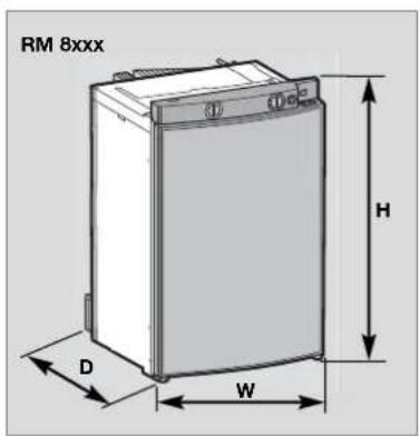
text_image
RM 8xxx D W H
natural_image
Line drawing of a RML 8xxx battery casing (no text or symbols on the diagram itself)Fig. 3Fig. 2
Fig. 4
Technical data / models with curved door
| Model Dimensions | Gross capacityH x W x D (mm)Depth incl. door | with/without freezer comp. mfreezer comptmt. | Rating detailsains/battery electricity/gas weight Piezover 24hrs | Consumption * Net ignitionAutomat | |||
| RMS 8400 | 821x486x568 | 80 / 85 lit. | 8 lit. | 125 W / 120 W | ca.2,5 KWh / 270 g | 25 kg | • |
| RMS 8401 | 821x486x568 | 80 / 85 lit. | 8 lit. | 125 W / 120 W | ca.2,5 KWh / 270 g | 25 kg | |
| RMS 8405 | 821x486x568 | 80 / 85 lit. | 8 lit. | 125 W / 120 W | ca.2,5 KWh / 270 g | 25 kg | |
| RM 8400 | 821x486x568 | 90 / 95 lit. | 8 lit. | 135 W / 130 W | ca.2,4 KWh / 270 g | 27 kg | • |
| RM 8401 | 821x486x568 | 90 / 95 lit. | 8 lit. | 135 W / 130 W | ca.2,4 KWh / 270 g | 27 kg | |
| RM 8405 | 821x486x568 | 90 / 95 lit. | 8 lit. | 135 W / 130 W | ca.2,4 KWh / 270 g | 27 kg | |
| RMS 8460 | 821x486x633 | 90 / 96 lit. | 11 lit. | 125 W / 120 W | ca.2,5 KWh / 270 g | 26 kg | • |
| RMS 8461 | 821x486x633 | 90 / 96 lit. | 11 lit. | 125 W / 120 W | ca.2,5 KWh / 270 g | 26 kg | |
| RMS 8465 | 821x486x633 | 90 / 96 lit. | 11 lit. | 125 W / 120 W | ca.2,5 KWh / 270 g | 26 kg | |
| RMS 8500 | 821x523x568 | 90 / 96 lit. | 9 lit. | 125 W / 120 W | ca.2,5 KWh / 270 g | 26 kg | • |
| RMS 8501 | 821x523x568 | 90 / 96 lit. | 9 lit. | 125 W / 120 W | ca.2,5 KWh / 270 g | 26 kg | |
| RMS 8505 | 821x523x568 | 90 / 96 lit. | 9 lit. | 125 W / 120 W | ca.2,5 KWh / 270 g | 26 kg | |
| RMS 8550 | 821x523x623 | 103/110 lit. | 12 lit. | 125 W / 120 W | ca.2,6 KWh / 270 g | 27 kg | • |
| RMS 8551 | 821x523x623 | 103/110 lit. | 12 lit. | 125 W / 120 W | ca.2,6 KWh / 270 g | 27 kg | |
| RMS 8555 | 821x523x623 | 103/110 lit. | 12 lit. | 125 W / 120 W | ca.2,6 KWh / 270 g | 27 kg | |
| RM 8500 | 821x523x568 | 100/106 lit. | 9 lit. | 135 W / 130 W | ca.2,4 KWh / 270 g | 28 kg | • |
| RM 8501 | 821x523x568 | 100/106 lit. | 9 lit. | 135 W / 130 W | ca.2,4 KWh / 270 g | 28 kg | |
| RM 8505 | 821x523x568 | 100/106 lit. | 9 lit. | 135 W / 130 W | ca.2,4 KWh / 270 g | 28 kg | |
| RM 8550 | 821x523x623 | 115/122 lit. | 12 lit. | 135 W / 130 W | ca.2,6 KWh / 270 g | 30 kg | • |
| RM 8551 | 821x523x623 | 115/122 lit. | 12 lit. | 135 W / 130 W | ca.2,6 KWh / 270 g | 30 kg | |
| RM 8555 | 821x523x623 | 115/122 lit. | 12 lit. | 135 W / 130 W | ca.2,6 KWh / 270 g | 30 kg | |
| RML 8550 | 1245x523x625 | 179/189 lit. | 33 lit. | 190 W / 170 W | ca.3,2 KWh / 380 g | 45 kg | • |
| RML 8551 | 1245x523x625 | 179/189 lit. | 33 lit. | 190 W / 170 W | ca.3,2 KWh / 380 g | 45 kg | |
| RML 8555 | 1245x523x625 | 179/189 lit. | 33 lit. | 190 W / 170 W | ca.3,2 KWh / 380 g | 45 kg | |
| RMSL 8500 | 1245x523x568 | 145/155 lit. | 28 lit. | 190 W / 170 W | ca.3,2 KWh / 380 g | 40 kg | • |
| RMSL 8501 | 1245x523x568 | 145/155 lit. | 28 lit. | 190 W / 170 W | ca.3,2 KWh / 380 g | 40 kg | |
| RMSL 8505 | 1245x523x568 | 145/155 lit. | 28 lit. | 190 W / 170 W | ca.3,2 KWh / 380 g | 40 kg | |
Subject to technical changes.
*Average consumption measured at an average ambient temperature of 25°C in pursuance of ISO Standard.
Technical data / models with flat door
| Model Dimensions | Gross capacityH x W x D (mm)Depth incl. door | with/without freezer comp. mfreezer comptmt. | Rating detailsains/battery electricity/gas weight Piezo over 24hrs | Consumption * Net ignitionAutomat | |||
| RMS 8500 | 821x523x541 | 86 / 92 lit. | 9 lit. | 125 W / 120 W | ca.2,5 KWh / 270 g | 26 kg | • |
| RMS 8501 | 821x523x541 | 86 / 92 lit. | 9 lit. | 125 W / 120 W | ca.2,5 KWh / 270 g | 26 kg | |
| RMS 8505 | 821x523x541 | 86 / 92 lit. | 9 lit. | 125 W / 120 W | ca.2,5 KWh / 270 g | 26 kg | |
| RMS 8550 | 821x523x596 | 99 /106 lit. | 12 lit. | 125 W / 120 W | ca.2,6 KWh / 270 g | 27 kg | • |
| RMS 8551 | 821x523x596 | 99 /106 lit. | 12 lit. | 125 W / 120 W | ca.2,6 KWh / 270 g | 27 kg | |
| RMS 8555 | 821x523x596 | 99 /106 lit. | 12 lit. | 125 W / 120 W | ca.2,6 KWh / 270 g | 27 kg | |
| RM 8500 | 821x523x541 | 96 /102 lit. | 9 lit. | 135 W / 130 W | ca.2,4 KWh / 270 g | 28 kg | • |
| RM 8501 | 821x523x541 | 96 / 102lit. | 9 lit. | 135 W / 130 W | ca.2,4 KWh / 270 g | 28 kg | |
| RM 8505 | 821x523x541 | 96 / 102lit. | 9 lit. | 135 W / 130 W | ca.2,4 KWh / 270 g | 28 kg | |
| RM 8550 | 821x523x596 | 111 /118 lit. | 12 lit. | 135 W / 130 W | ca.2,6 KWh / 270 g | 30 kg | • |
| RM 8551 | 821x523x596 | 111 /118 lit. | 12 lit. | 135 W / 130 W | ca.2,6 KWh / 270 g | 30 kg | |
| RM 8555 | 821x523x596 | 111 /118 lit. | 12 lit. | 135 W / 130 W | ca.2,6 KWh / 270 g | 30 kg | |
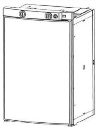
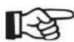
3.4 Description of refrigerator
text_image
RMx 8xx0 / Battery igniter Dometic RMx 8xx1 / MES DometicFig. 5
RMx 8xx5 / AES
1 Operating controls
2 Door locking button
3 Freezer compartment (removable)
4 Insertable grid shelf (available as option, to be used when freezer compartment is removed)
5 Post-evaporator for cooling compartment
6 Condensation water drain channel
7 Vegetable bin
8 Upper door shelf with flap, egg shelf available as option may be inserted
9 Lower door shelf with bottle holders
4.0 Refrigerator operation
The refrigerator is equipped to operate on three power modes:
■ Mains voltage (230V AC)
■Direct-current voltage (12V DC)
■Gas (liquid gas propane/butane)
Select the desired power mode by the energy selector switch (battery igniter type models) or the energy selector button (MES, AES).
Appliances with automatic energy selection (AES) are additionally provided with "automatic mode" function. Then the AES system automatically selects the best energy source for each particular situation.
i
■When the appliance is first put into operation, there may be a mild odour which will disappear after a few hours.
■Park the vehicle level, particularly when starting up the refrigerator and filling with food before starting a journey.
■The cooling unit is silent in operation.
The refrigerator will take several hours to reach its operating temperature in the cooling compartment. The freezer compartment should be cold about one hour after switching on the refrigerator.
4.1 Cleaning
Before starting up the refrigerator, it is recommended that you clean it inside and repeat this at regular intervals.
Use a soft cloth and lukewarm water with a mild detergent. Then wipe out the appliance with clean water and dry thoroughly.
Keep the condensation water drain channel free of deposits.
To avoid material alterations, do not use soap or hard, abrasive or soda-based cleaning agents. Do not allow the door seal to come into contact with oil or grease.
4.2 Maintenance
In compliance with the applicable regulations, please note that the gas unit and the connected ventilation ducts must be checked by authorised technical personnel after first use and after every other year for compliance with the European Standard EN 1949. A test certificate has to be issued. It is the user's responsibility to arrange this test.
The gas burner must be inspected and cleaned as necessary at least once a year. When using liquefied petroleum gas (tank or refill cylinders) the maintenance interval is reduced to half-yearly or quarterly.
Keep the evidence of maintenance work carried out on your refrigerator.
■Work on gas and electrical equipment shall be carried out by qualified personnel only.
It is recommended that this is carried out by an authorised customer services department.
We recommend maintenance following an extended shutdown of the vehicle. Please contact our customer services.
4.3 Electrical operation
12V-voltage (on-board power supply)
CAUTION!
The refrigerator should only be used in 12VDC-operation while the vehicle's engine is running, otherwise the on-board-battery would be discharged within a few hours!
Mains power (230V)
CAUTION!
This option should only be selected where the supply voltage of the connection for power supply corresponds to the value specified on the data plate. Any difference in values may result in damage the appliance.
4.4 Gas operation (liquid gas)
■The refrigerator must be operated using liquid gas (propane, butane) (no natural gas or town gas).
■When using LPG gas, please consider that the burner needs cleaning at shorter intervals due to the gas combustion method (2 - 3 times per year recommended.
In Europe, gas operation is permitted while travelling only on the condition that the gas system of the vehicle is equipped with a hose rupture protection. The national regulations of the respective country must be observed.
For physical reasons, gas ignition faults could occur starting from an altitude above sea level of approx. 3280 ft. / 1000 m (No malfunction!)
On the initial refrigerator start-up or after a cylinder change, air may be trapped in the gas line. To purge the air from the lines, switch on the refrigerator and any other gas appliances (e.g. stove) for a short time. The gas ignites without delay.
■ Each refrigerator with manual ignition is equipped with an automatic flame safety valve which interrupts the gas supply automatically after approx. 30 seconds when the flame has extinguished.

WARNING!
As a basic rule, gas operation is prohibited in petrol stations!
Prior to starting the refrigerator in gas mode :
■Open the gas cylinder valve.
■Open the shut-off valve for gas supply to the refrigerator.
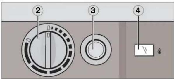
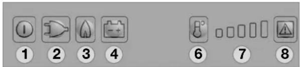
4.5 Explanation of operating controls
NOTE!
Proceed to the description that applies to YOUR model.
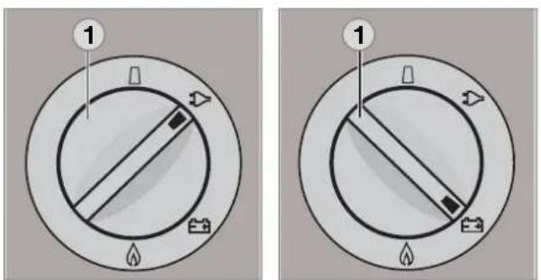
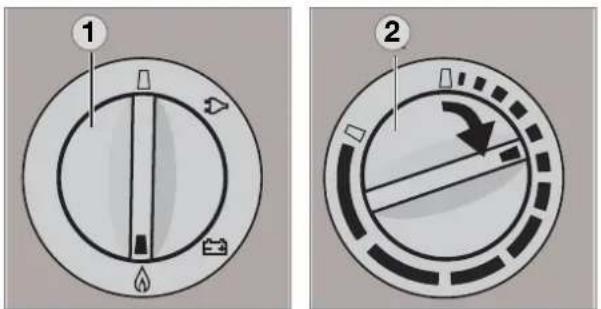
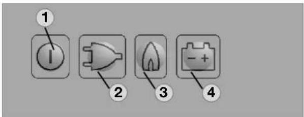
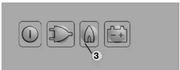
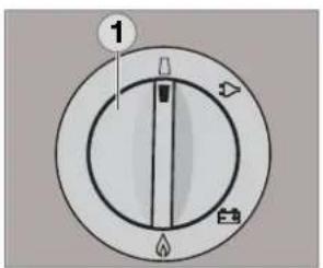
Manual energy selection / manual ignition battery igniter (RM 8xx0) :
1= Power On switch / Energy selector switch
2 = Temperature controller
3 Battery igniter (gas)
4 Flame indicator (galvanometer)
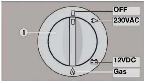
text_image
OFF 230VAC 12VDC GasFig. 6
text_image
Diagram showing four labeled circular components with numbered annotations, likely illustrating a control or measurement setup.Fig. 7
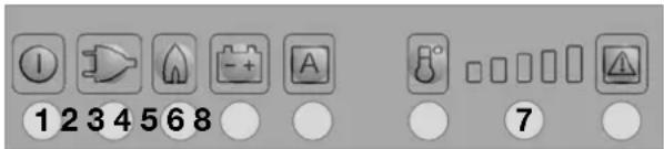
Manual energy selection / automatic ignition MES (RM 8xx1) :
text_image
Dometic 1 2 3 4 6 7 8Fig. 8
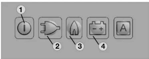
1 = Power ON/OFF switch
2 = Energy selector button 230V AC
3 = Energy selector button GAS
4 = Energy selector button 12V DC
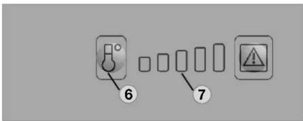
6 = Temperature level selection
7 = Temperature level display
8 = Indicator LED failure / Reset button GAS FAILURE
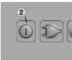
Switching ON/OFF
■Switch ON by pressing button (1), 2s
■Switch OFF by pressing button (1), > 2s
230V AC operation
■ Select "Mains voltage" by pressing button (2)
■ Set temperature step by pressing button (6)
12V DC operation (vehicle's battery)
■ Select "Battery voltage" by pressing button (4)
■ Set temperature step by pressing button (6)
Gas operation
■Select "Gas" by pressing button (3)
■ Set temperature step by pressing button (6)
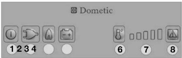
Automatic energy selection / automatic ignition AES (RM 8xx5) :
text_image
Dometic 1 2 3 4 5 6 87Fig. 9
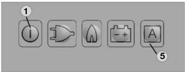
1 = Power ON/OFF switch
2 = Energy selector button 230V AC
3 = Energy selector button GAS
4 = Energy selector button 12V DC
5 = Selector button "AUTOMATIC"
6 = Temperature level selection
7 = Temperature level display
⑧ = Indicator LED failure /
Reset button GAS FAILURE
Switching ON/OFF
■Switch ON by pressing button (1), 2s
■Switch OFF by pressing button (1), > 2s
Manual operation
■Select energy source with buttons (2,3,4)
■ Set temperature step by pressing button (6)
Automatic operation
■ Change over to "Automatic" with button (5)
Automatical energy selection (if available)
Sequence of priority: 1.) Solar (12V DC)
2.) 230V AC
3.) 12V DC
4.) Liquid gas
■ Set temperature step by pressing button (6)
4.6 RM 8xx0 models
Appliances with battery igniter (manual energy selection)
4.6.1 Electrical operation
text_image
1 1Fig. 10
Switch on the appliance by turning the energy selection switch (1) clockwise to position :

230V operation,

12V operation.
4.6.2 Gas operation
text_image
Diagram showing two circular gauges labeled 1 and 2 with directional arrows and symbols, likely illustrating a mechanical or electrical component.Fig. 12
-
Turn the rotary selector switch (1) to position ⬆ .
-
Turn the temperature selector (2) clockwise and push. Keep the controller button depressed.
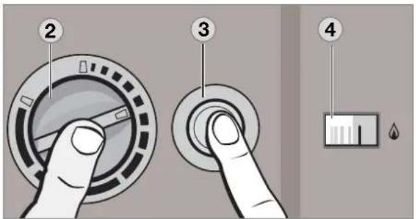
text_image
Diagram showing a hand pressing down on a circular dial with labeled parts 2, 3, and 4, alongside a droplet symbol.Fig. 14
- Then, press knob (3) of battery igniter down and keep it depressed. The ignition process is activated automatically.
- Once the flame ignites, the pointer of galvanometer (4) begins moving into the green range. The refrigerator is operational. Keep knob (2) depressed for approx. 15 seconds and finally release it.
4.6.3 Setting of cooling compartment temperature
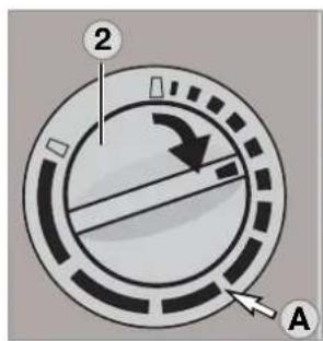
text_image
2 AFig. 15
Select the desired cooling compartment temperature by turning the rotary knob (2).
The scale starts with MIN position (small bar = highest temperature) and climbs up to MAX position
(large bar = lowest temperature).
Note: The temperature levels do not relate to absolute temperature values.
i
Please select the medium setting (A) for ambient temperatures between +15°C and +25°C. The unit operates within its optimum performance range.
■ 12V operation: The refrigerator operates without thermostatic control (continuous operation).
4.7 RM 8xx1 models
MES appliances (manual energy selection)
4.7.1 Electrical operation
text_image
① ② ③ ④Fig. 16
To start the refrigerator, press button (1) for 2 seconds.
The refrigerator starts with the last selected type of energy.
230V operation :
Press button (2):

12V operation :
Press button (4):

4.7.2 Gas operation
text_image
① ③Fig. 17
Gas operation :
Press button (3):

The ignition process is activated automatically by means of an automatic igniter.

The flame extinguishes after reaching the pre-set cooling compartment temperature and ignites again if the cooling compartment temperature increases again. If the flame is not lit after the first ignition attempt, the automatic igniter repeats the ignition twice (duration 30 s) at time intervals of 2 minutes. If the flame is not lit afterwards, a fault is indicated.
4.7.3 Setting of cooling compartment temperature
text_image
6 7Fig. 18
Select the desired cooling compartment temperature by pressing button (6).
The LED display (7) of the selected temperature setting is illuminated.
The scale starts with MIN position at the left LED position (small bar = highest temperature) and climbs up to MAX position at the right LED position (large bar = lowest temperature). Note: The temperature levels do not relate to absolute temperature values.
4.8 RM 8xx5 models
AES appliances (manual + automatic energy selection)
4.8.1 Manual operation
text_image
1 2 3 4 AFig. 19
To start the refrigerator, press button (1) for 2 seconds.
The refrigerator starts with the last selected type of energy.
230V operation :
Press button (2):

12V operation :
Press button (4):

Gas operation :
Press button (3) :

4.8.2 Automatic operation
text_image
1 5Fig. 20
To start the refrigerator, press button (1) for 2 seconds.
The refrigerator starts with the last selected type of energy.
Automatic operation :
Press button (5): A
Upon switching on, the electronics automatically selects one of the three possible energy types: 230V - 12V - liquid gas. The control electronics automatically ensures that the refrigerator is supplied with the optimum source of energy in each respective case.
Sequence of priority: 1.) Solar (12V DC)
2.) 230V AC
3.) 12V DC
4.) Liquid gas

If sufficient mains voltage is available (more than 195 V), this power source is selected as prime option. If a solar system capable of powering the refrigerator is installed, the solar 12V supply takes priority.
The 12V operation is otherwise only effective while the engine is running.
According to the sequence of priority the electronics selects GAS as energy source only, if both of the electrical energy source are not available.
Manual operation is possible at any time.
4.8.3 Setting of cooling compartment temperature
see point 4.7.3 Setting of cooling compartment temperature.
4.8.4 Refuelling while in AES mode operation

In order to prevent unintended switching to gas operation during refuelling, the electronic system starts gas operation of the refrigerator after the motor has been turned off for 15 minutes. During this period the appliance is ready for operation ("stand-by"). The temperature level LEDs do not light then while all other indicators remain active.

WARNING!
The use of unshielded flames is prohibited in petrol station environments.
Should the refuelling stop last longer than 15 minutes, the refrigerator has to be switched off or switched over to another energy type.
4.8.5 Additional features (MES / AES)
The brightness of the display reduces after a few seconds if no other buttons are pressed. The indicator lights again if a button is pressed. Press the button again to activate the required function.
■Failures are indicated by flashing of the failure indicator LED.
■Should the door be kept open for too long (more than 2 minutes), an acoustic signal is initiated (pulsing whistle tone).
■Should the electronic control detect any failure, an acoustic signal will sound (pulsing whistle tone). At the same time the display starts flashing (please refer to section Information on failure display and troubleshooting).
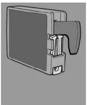
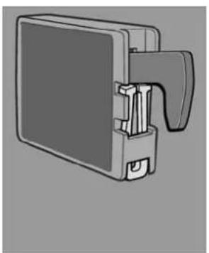
4.9 Self-contained gas operation and optional battery compartment
An optional battery compartment in the electronics case for internal (self-contained) power supply of the electronics is available for the model variants RM 8xx1 (appliances with electronics).
text_image
Domestic 1Battery compartment
Fig. 21

Batteries are not included!
Load the battery compartment with batteries (8 x AA 1.5 V) before operating the refrigerator.
Self-contained gas operation
All operating modes can be selected while the on-board 12 V DC power supply is active. The battery compartment is disconnected from the power supply.
If the vehicle on-board 12 V DC power supply is not present or there is an interruption of the mains power supply during operation, the electronics automatically switch to the appliance internal battery power supply.
The refrigerator can now only be operated in the gas mode.
All LED indicators except the GAS LED are not lit during operation with the batteries inside the appliance. The GAS LED flashes every 15 seconds.
If a button is pressed, the temperature level LEDs (7, Fig. 8) also light.
If the voltage of the battery inside the appliance is too low, an acoustic signal (whistle tone) sounds every 15 seconds.
Then replace the batteries in the battery compartment
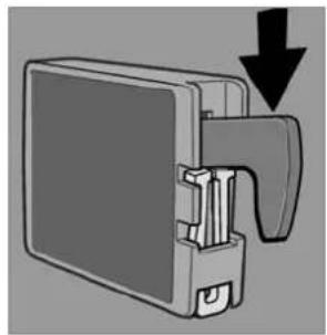
4.9.1 Inserting / changing the batteries
Switch off the refrigerator, as described in section Shutting of the refrigerator.
text_image
Dometic pressOpening battery compartment
Fig. 22

text_image
Domestic pull outPulling out battery compartment
Fig. 23
CAUTION!
■ Remove discharged batteries.
■Replace the batteries completely.
- Do not mix different types of batteries.
- Observe the correct polarity!
- Do not connect non-rechargeable batteries to a charger.
■Remove rechargeable batteries from the battery compartment before charging.
■ Avoid short circuits on the contacts in the battery compartment!
■ Remove the batteries from the battery compartment if the refrigerator will not be used for a long time.

Protect the environment!
Do not dispose of batteries in domestic waste. Take your used batteries to your dealer or acollection point.
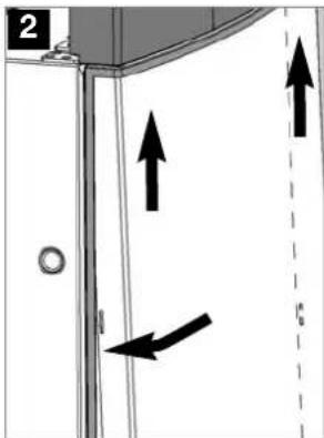
4.10 Door locking

CAUTION!
As a basic rule, shut and lock the refrigerator before you start your journey!
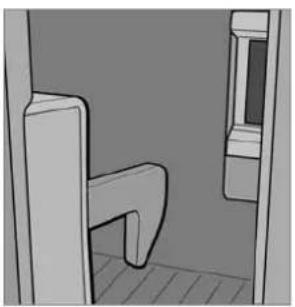
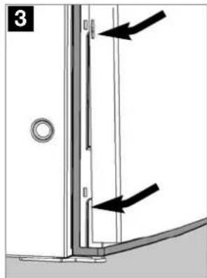
natural_image
Diagram showing a kitchen sink with a water drop and two circular fixtures on a tray (no text or symbols)Fig. 24

natural_image
Simple line drawing of a room corner with a curved door and window (no text or symbols)Fig. 25
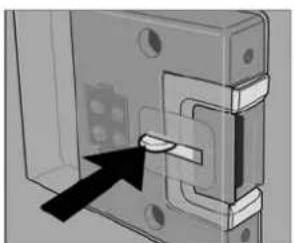
Open the door by pressing the locking button and pull open (see Fig. 24).
Shut the door again by pushing it to close. The snapping into the lock can be heard.
While the vehicle is parked, the locking hook may be fixed to facilitate opening of the door (Fig. 26-27).
4.10.1 Fastening and releasing the door lock hook when parking the vehicle
If the vehicle is parked for a longer period of time, the locking hook may be clamped by means of a lockbar. The door may now be opened by just pulling it without need of pressing the locking button.
natural_image
Mechanical component diagram showing a bracket with a handle and arrow indicating direction (no text or symbols)Fastening

natural_image
Illustration of a mechanical device with a handle and internal components (no text or symbols)Fig. 26
Fig. 27
natural_image
Diagram of a mechanical component with a downward arrow indicating force or direction (no text or symbols present)Releasing

natural_image
Technical illustration of a mechanical component with a handle and mounting bracket (no text or symbols)Fig. 28
Fig. 29
4.11 Lighting
The interior lighting is controlled using a door contact. Should the door be kept open more than 2 minutes, an acoustic signal is initiated (pulsing whistle tone), except for models with battery igniter.

natural_image
Mechanical assembly diagram showing a piston-like component with motion indicators (no text or symbols)Fig. 30

Please contact the authorized Dometic Service if a failure occurs.
4.12 Positioning the storage racks
natural_image
Diagram of a metal rack structure with an arrow pointing to it, no text or symbols presentFig. 31
The storage racks may be pulled out by smoothly lifting them and may be positioned as desired.
4.13 Removable freezer compartment
text_image
Diagram illustrating three steps of a door lock mechanism: first, second, and third, with numbered arrows indicating sequence.Fig. 32
To enlarge the cooling compartment, just remove the freezer compartment.
- Unlock the freezer compartment on both sides.
- Pull the freezer compartment out.
Store the freezer compartment safely in order to prevent damage

Once the freezer compartment is removed, an additional storage rack (3.) may be installed. The storage rack is a piece of extra equipment and may be obtained by Dometic.
4.14 Exchange of the igniter's battery
Appliances with battery igniter (RM 8xx0)
text_image
1 1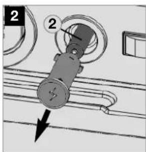
text_image
Technical diagram showing a mechanical component with numbered parts and directional arrow indicating motion or forceFig. 34Fig.
Unlock the battery (2) by depressing and turning the button (1) approx. 90° counter-clockwise (by means of a suitable screw driver). After removing the cap, the battery (1.5 V AAA/R3/Micro) can be removed and replaced. Observe correct polarity!
4.15 Operation during low outside temperatures
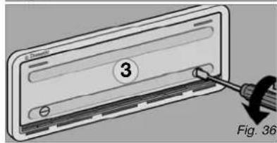
Check that the ventilation grilles and the exhaust (1) duct system (2) have not been blocked by snow, leaves, etc. .
Cold air can restrict the performance of the unit. Install the winter covers (3) if you discover any loss of cooling performance when outdoor temperatures are low. This protects the unit against excessively cold air.
Ventilation grille LS100
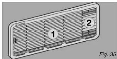
natural_image
Diagram of a ventilation grille with numbered components (1 and 2), no text or symbols presentVentilation grille LS200 + winter cover
text_image
3 Fig. 36CAUTION!
Refrigerators up to 130 l capacity * : Do not install the top winter cover during gas operation.
* See Technical Data or information on the rating plate.
You should also attach both winter covers if the vehicle is taken out of service for a longer period of time or while it is being cleaned from the outside.

The following ventilation grille combinations can be installed on your vehicle: LS 100 and LS 200 or two LS 200 for refrigerators up to 130 l capacity; two LS 300 (not shown) for refrigerators with more than 130 l capacity.
Pay attention to this when purchasing winter covers.
For the ventilation grille LS 300, Dometic provides the Winter Set EWS 300 which can be used at very low temperatures from +5 °C to -30 °C.
4.16 Storing food and making ice cubes
4.16.1 Storing products in the cooling compartment
■Switch the refrigerator on approx. 12 hours before filling it.
■Always store pre-cooled foods in the refrigerator. Make sure that the food is well cooled when it is bought and also when transporting it. Use insulated cooling bags.
■Open the refrigerator door only for a short period of time when removing products.
■Products must be packed - best of all in closed containers, wrapped in aluminium foil or similar - and stored separately from each other, in order to prevent drying out or odours.
- Allow foods that have been warmed up to cool down before storing.
■Avoid storing products in the refrigerator that could emit volatile flammable gases.
- Do not overfill the storage grids and compartments to prevent obstructing the internal air circulation.
- Maintain a clearance of approx. 10 mm between chilled products and post-evaporator ("cooling fins").
- Do not expose the refrigerator to direct sunlight. Please bear in mind that the temperature inside a closed vehicle increases sharply if exposed to sunlight and that this can reduce the efficiency of the refrigerator.
■ Ensure that air circulation of the cooling unit is not obstructed. Keep the ventilation grilles free from obstructions.
4.16.2 Storing products in the freezer compartment
■ Do not keep carbonated drinks in the freezer.
■The freezer compartment is suitable for making ice cubes and for short-term storage of frozen food. It is not suitable as a means of freezing foods.
When ambient temperatures are lower than +10°C and the refrigerator is exposed to these temperatures for extended periods of time, an even regulation of freezer temperature cannot be guaranteed for system-related reasons. This can cause the temperature in the freezer to rise and the stored goods to melt.
4.16.3 Refrigerator compartments
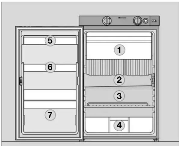
text_image
① ② ③ ④ ⑤ ⑥ ⑦Fig. 37
1 Freezer compartment : already frozen food (deep-frozen food)
② Middle compartment: Dairy products, convenience food
③ Bottom compartment: Meat, fish, food for defrosting
4 Vegetable compartment: Salads, vegetables, fruit
⑤ Top door shelf: Eggs, butter
6 Middle door shelf: Cans, dressings, ketchup, jam
⑦ Bottom door shelf (drinks compartment):
Drinks in bottles or bags
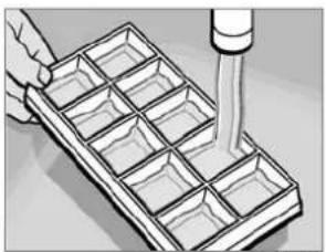
4.16.4 Making ice cubes
Ice cubes are best frozen overnight. At night, the refrigerator has less work to do and the unit has more reserves.
natural_image
Illustration of a hand using a pipette to process a grid-patterned tray (no text or symbols visible)Fig. 38

natural_image
3D illustration of a rectangular block with a grid pattern on top, placed on a flat surface (no text or symbols)Fig. 39
-
Fill the ice cube tray with drinking water.
-
Place the ice cube tray in the freezer compartment.

WARNING!
Only use drinking water!
4.17 Shutting off the refrigerator
text_image
1Fig. 40
text_image
2 IFig. 41
natural_image
Mechanical component with a black arrow pointing to a specific part (no text or symbols visible)Fig. 42

natural_image
Pure mechanical assembly diagram showing a piston and housing component without any text or symbolsFig. 43
For battery igniter models, set energy selector switch (1) to position "OFF". The appliance is switched off (Fig. 40).
■Switch off MES and AES models by pressing button (2). Keep button (2) pressed for 3 seconds. The display disappears
and the appliance is fully switched off (Fig. 40).
■ Release the locking mechanism of the door lock by pushing it and shift it to the front. If the door is shut in this position, a small gap is nevertheless kept open to prevent formation of mildew.
If the refrigerator is to be taken out of service for an extended period of time, close the onboard shut-off valve and the cylinder valve.
4.18 Defrosting
As time goes by, frost builds up on the fins inside the refrigerator. A layer of frost thicker on one side may occur and does not represent a malfunction. When this layer of frost is about 3 mm (0.118 inches) thick, the refrigerator should be defrosted.
■Switch off the refrigerator, as described in section Shutting of the refrigerator.
■Remove all food and the ice cube tray.
Leave the refrigerator door open to allow air to enter and to prevent formation of mildew.
■ After defrosting (freezer compartment and fins free of frost), wipe both cooling compartments dry with a cloth.
Note: Water thawing in the main compartment of the refrigerator runs into an appropriate container at the back of the refrigerator. From there, the water evaporates. Place a cloth in the freezer compartment and in the cooling compartment to collect excess water before defrosting.
CAUTION!
The layer of ice must never be removed forcibly, nor may defrosting be accelerated using a heat source!
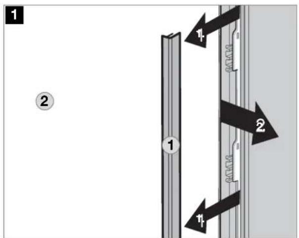
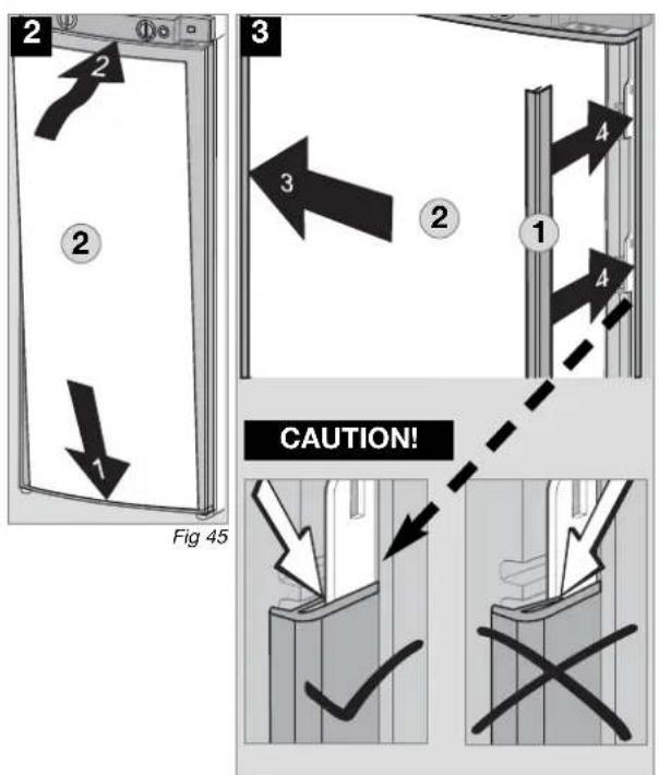
4.19 Changing the decor panel
Model RMS 84xx, RM 8xxx, RM(S)L 8xxx (with frame)
■Remove the lateral ledge (1) the door (ledge is attached, not screwed).
Shift decor panel (2) away from the door and insert the new decor panel. Re-attach ledge (1).
text_image
1 2 1 2 1Fig. 44
text_image
2 2 1 3 2 1 4 CAUTION! Fig 45Fig. 46
Decor panel dimensions (frame) :
RMS 84xx, RM 8xxx
Casing width 486 mm
Height Width Thickness
743 +/- 0.5 mm 472.5 +/- 0.5 mm max. 1.7 mm
Casing width 523 mm
Height Width Thickness
743 +/- 0.5 mm 508 +/- 0.5 mm max. 1.7 mm
RM(S)L 8xxx
Casing width 523 mm
Height Width Thickness
1169.5 +0/-1 mm 507.5 +0/-1 mm max. 1.7 mm
Model RMx(L) 8xxx (Inserting of frameless decor panel)
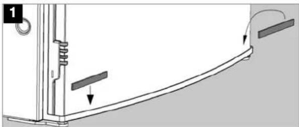
natural_image
Technical diagram of a mechanical assembly with arrows indicating motion or force direction (no text or symbols)Fig. 47
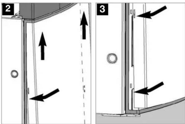
text_image
Technical diagram showing two mechanical assembly steps with directional arrows and labeled componentsFig. 48 Fig. 49

natural_image
Diagram of a door corner with two arrows pointing to a corner detail (no text or symbols)Fig. 50
4.20 Trouble-shooting
Failure: The refrigerator does not cool sufficiently.
| Possible cause | Action you can take |
| - Inadequate ventilation to the unit.- Thermostat setting is too low.- The condenser is heavily frosted.- Too much warm food has been stored inside within short period of time.- The appliance has been running for only a short period of time.- Ambient temperatures too high. | - Check that ventilation grilles are not covered.- Set thermostat to a higher level.- Check that the refrigerator door closes properly.- Allow warm food to cool down before storage.- Check whether the cooling compartment works after approx. 4 - 5 hours.- Regularly remove ventilation grilles. |
Failure: The refrigerator does not cool in gas operation mode.
| Possible cause | Action you can take |
| - Gas cylinder empty.- Is the upstream shut-off device open?- Air in the gas pipe? | - Change gas cylinder.- Open shut-off device.- Switch off the appliance and start again. Repeat this procedure 3 - 4 times, if necessary |
Failure: The refrigerator does not cool in 12V operation.
| Possible cause | Action you can take |
| - On-board fuse defective.- On-board battery discharged.- Engine not running.- Heating element defective (please also refer to failure indication). | - Fit new fuse.- Check battery, charge it.- Start engine.- Please inform the Dometic Customer Service |
Failure: The refrigerator does not cool in 230V operation.
| Possible cause | Action you can take |
| - On-board fuse defective.- Vehicle not connected to mains supply voltage.- AES: Gas operation despite connection to the mains supply voltage?- Heating element defective (please also refer to failure indication). | - Fit new fuse.- Make a connection to a mains power supply.- Appliance switches to gas operation due to insufficient mains supply voltage (automatically switches back to 230V operation).- Please inform the Dometic Customer Service. |
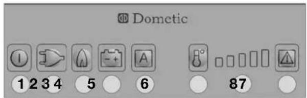
4.21 Information on failure display and trouble-shooting
■Refrigerators with an electronics system (MES, AES) indicate the occurrence of a malfunction by the LED or display flashing.
If a malfunction occurs, the indicator LED "Failure" (8) flashes simultaneously. In the case of AES models an acoustic alarm sounds.
4.21.1 Status indicators
text_image
1 2 3 4 6 7 8MES
Fig. 51
1 = Button ON / OFF
2 = Energy selector switch 230V AC
3 = Energy selector switch GAS
4 = Energy selector switch 12V DC
Before notifying the authorised Service Center, please check whether:
■the instructions in section "Operating the refrigerator" have been observed.
■ the refrigerator stands level.
■it is possible to operate the refrigerator with any available power source.
text_image
1 2 3 4 5 6 8 7AES
Fig. 52
5 = selector switch "AUTOMATIC"
6 = temperature level button
7 = temperature level display
8 = fault LED / GAS FAULT reset button
Operation with on-board 12 V power supply
| Indicator | Fault | Remedy | |
 | flashing + acoustic signal 20 s | 230V mode: "230V" not available or voltage too low | Check mains power connection, mains voltage, fuse |
 | flashing + acoustic signal 20 s | 12V mode: "12 V" not available or voltage too low | Check 12 V connection, on-board battery, fuseAES: Check D+ signal |
 | flashing + acoustic signal 20 s | GAS/Automatic mode: Flame not ignited | Check gas supply (gas bottle, gas valve)Press the (8) button after clearing the fault. |
| Acoustic signal, 15 s, at 2 minute intervals | Interior lighting is swit-ched on | Close door, check door contact | |
 | flashing + acoustic signal 20 s | 230V mode: 230V heating element defective | Arrange replacement of 230V heating element, contact Customer Service |
 | flashing + acoustic signal 20 s | 12V mode: 12V heating element defective | Arrange replacement of 12V heating element, contact Customer Service |
| 7 | flashing | without contact or defective | contact Customer ServiceTemperature sensor |
 | flashing + acoustic signal 20 s | Burner defective or coo-ling unit defective | Check burner, burner nozzles, if necessary contact Customer Service and arrange replacement |
Operation with batteries (internal power supply)
| Indicator | Fault | Remedy |
| 3 flashingbrightly8 | Flame not ignited | Check gas supply (gas bottle, gas valve)Press the (8) button after clearing the fault. |
| 3 flashingbrightly7 | Burner defective or cooling unit defective | Check burner, burner nozzles, if necessary contact Customer Service and arrange replacement |
| Acoustic signal at 15 second intervals | Undervoltage detection (internal batteries) | Replace batteries |
| Automatic switching from external to internal power supply does not function(absence of the on-board 12 V power supply for the electronics) | Refrigerator does not function;gas operation not possible although the batteries are inserted. | Switch off the refrigerator and start again.The on-board power supply was interrupted during the starting of the gas operation.Note: No automatic switching is performed during the ignition. |
Mode d'emploi
natural_image
Line drawing of a white refrigerator with control panel and door (no text or symbols)Type C40 / 110
CE
E _1
10 R - 047358
N4
MBA 12/2014
FR

Pour votre sécurité

AVERTISSEMENT !
DECLARATION OF CONFORMITY
according to
Low Voltage Directive 73/23/EEC and
the Amendment to LVD 2006/95/EC
EMC Directive 2004/108/EC
Automotive Directive 72/245/EEC and
the Amendment 95/54/EC, 2009/19/EC
Gas Appliance Directive 2009/142/EC
End-of-Life Vehicle Directive 2000/53/EC
RoHS Directive 2002/95/EC
Type of equipment
Brand Name
Type family
Manufacturer's (Factory)
name
address
telephone no
telefax no
Absorption Refrigerator
DOMETIC
C 40/110
DOMETIC GmbH
The following harmonized standards or technical specifications (designations) which comply with good engineering practice in safety matters in force within the EEA have been practiced:
EN 60335-1;02. (IEC 60335-1; 4 ed., Am. 1, Am. 2),
EN 60335-2-24,03 (IEC 60335-2-24; 6 ed., Am. 1, Am. 2)
EN 61000-3-2;00, A1, A2, A14 EN 61000-3-3;95, A1,
EN 55014-1:07, A1, A2 EN 55014-2:01, A1
The equipment conforms completely with the above stated harmonized standards or technical specifications.
By signing this document, the undersigned declares as manufacturer, or the manufacturer's authorized representative established within the EEA, that the equipment in question complies with the requirements stated above.
Date
2012.01.04
Position
General Manager

natural_image
Technical line drawing of a refrigerant appliance with no visible text or symbols
text_image
RM 8xxx P L H
natural_image
Line drawing of a RML 8xxx battery casing (no text or symbols on the diagram itself)Tension continue (12V CC)
ATTENTION!
text_image
Diagram showing four labeled circular components with numbered annotations, likely illustrating a control or measurement system.Fig. 7
text_image
Diagram showing two circular gauges labeled 1 and 2, with arrows indicating direction of movement or change.Fig. 12
text_image
Diagram showing hand press control buttons labeled 2, 3, and 4 for a device operationFig. 14
text_image
① I ② 2 3 - + ④ AFig. 19
text_image
Domestic 1natural_image
Diagram showing a kitchen sink with a water drop and two circular fixtures, no text or symbols presentFig. 24

natural_image
3D rendering of a simple room corner with a curved door and adjacent window (no text or symbols)Fig. 25
natural_image
Diagram of a mechanical device with an arrow indicating direction (no text or symbols present)Attacher
natural_image
Illustration of a mechanical device with a handle and internal components (no text or symbols)Fig. 26
Fig. 27

natural_image
Diagram of a mechanical component with a downward arrow indicating force or direction (no text or symbols present)Détacher

natural_image
Technical illustration of a mechanical component with a handle and mounting bracket (no text or symbols)Fig. 28
Fig. 29
4.11 Éclairage
natural_image
Mechanical assembly diagram showing a clamping mechanism with rotating components (no text or symbols)Fig. 30

natural_image
Diagram of a metal grid structure with an arrow pointing to it, no text or symbols presentFig. 31
text_image
Diagram illustrating three steps of a door latch mechanism: opening, lifting, and grating.Fig. 32
text_image
Diagram showing a mechanical component with labeled parts and directional arrow, likely illustrating a motion or assembly process.Fig. 34Fig. 33
natural_image
Diagram of a ventilation grille with numbered components (1 and 2), no text or symbols presenttext_image
Domestic B AFig. 37
natural_image
Illustration of a hand using a pipette to process a grid-patterned tray (no text or symbols visible)Fig. 39
natural_image
3D illustration of a rectangular block with a grid pattern, placed on a flat surface (no text or symbols)Fig. 40
natural_image
Mechanical component diagram showing a bracket with a highlighted section and arrow indicator (no text or symbols)Fig. 43

natural_image
Mechanical assembly diagram showing a component with a black arrow indicating direction (no text or symbols present)Fig. 44
text_image
② ① ① ② ②Fig. 44
text_image
2 2 1 3 2 1 4 4 ATTENTION! Fig. 45Fig. 46
natural_image
Technical diagram of a mechanical assembly with arrows indicating motion or force direction (no text or symbols present)Fig. 47

text_image
Technical diagram showing two mechanical assembly steps with directional arrows and labeled componentsFig. 48 Fig. 49

natural_image
Diagram showing a corner joint with two arrows indicating downward force or direction (no text or symbols present)Fig. 50
1 = Touche MARCHE/ARRÊT
natural_image
Line drawing of a white refrigerator with control panel and door (no text or symbols)Type C40 / 110
CE
E _1
10 R - 047358
N4
MBA 12/2014
ES

Para su seguridad

ADVERTENCIA!
DECLARATION OF CONFORMITY
according to
Low Voltage Directive 73/23/EEC and
the Amendment to LVD 2006/95/EC
EMC Directive 2004/108/EC
Automotive Directive 72/245/EEC and
the Amendment 95/54/EC, 2009/19/EC
Gas Appliance Directive 2009/142/EC
End-of-Life Vehicle Directive 2000/53/EC
RoHS Directive 2002/95/EC
Type of equipment
Brand Name
Type family
Manufacturer's (Factory)
name
address
telephone no
telefax no
Absorption Refrigerator
DOMETIC
C 40/110
DOMETIC GmbH
The following harmonized standards or technical specifications (designations) which comply with good engineering practice in safety matters in force within the EEA have been practiced:
EN 60335-1;02, (IEC 60335-1; 4 ed., Am. 1, Am. 2),
EN 60335-2-24:03 (IEC 60335-2-24; 6 ed., Am. 1, Am. 2)
EN 61000-3-2:00, A1, A2, A14 EN 61000-3-3:95, A1,
EN 55014-1:07. A1, A2 EN 55014-2:01. A1
The equipment conforms completely with the above stated harmonized standards or technical specifications.
By signing this document, the undersigned declares as manufacturer, or the manufacturer's authorized representative established within the EEA, that the equipment in question complices with the requirements stated above.
Date
2012.01.04

Position
General Manager

natural_image
Line drawing of a refrigerant appliance with no visible text or symbols on the device itself
text_image
RM 8xxx Al F An
natural_image
Line drawing of a RML 8xxx battery casing (no text or symbols on the diagram itself)Fig. 3Fig. 2
Fig. 4
text_image
Diagram showing four labeled circular components with numbered annotations, likely illustrating a control or measurement setup.Fig. 7
text_image
Diagram showing two circular gauges labeled 1 and 2, with arrows indicating direction of movement or change.Fig. 12
text_image
Diagram showing hand press control buttons labeled 2, 3, and 4 for a device operationFig. 14
text_image
Domestic 1Compartimento de pilas
Fig. 21

text_image
Dometic pulsarnatural_image
Diagram showing a kitchen sink with a water drop and two circular fixtures on a tray (no text or symbols)Fig. 24

natural_image
Simple line drawing of a room corner with a curved door and window (no text or symbols)Fig. 25
natural_image
Diagram of a mechanical component with an arrow indicating direction (no text or symbols present)Fijación

natural_image
Illustration of a mechanical device with a handle and internal components (no text or symbols)Fig. 26
Fig. 27

natural_image
Diagram of a mechanical component with a downward arrow indicating force or direction (no text or symbols present)Soltado

natural_image
Technical illustration of a mechanical component with a handle and mounting bracket (no text or symbols)Fig. 28
Fig. 29
4.11 Iluminación
natural_image
Mechanical assembly diagram showing a clamping mechanism with rotating components (no text or symbols)Fig. 30

natural_image
Diagram of a metal rack structure with an arrow pointing to it, no text or symbols presentFig. 31
text_image
Diagram illustrating three steps of a door latch mechanism: opening, lifting, and cooling a grater.Fig. 32
text_image
Diagram showing a mechanical component with labeled parts and directional arrow, likely illustrating a motion or assembly process.Fig. 34Fig.
natural_image
Diagram of a ventilation grille with numbered components (1 and 2), no text or symbols presentnatural_image
Diagram of a car door panel with a screwdriver inserted, labeled with number 3 and Fig. 36 (no text or symbols on the diagram itself)¡PRECAUCIÓN!
natural_image
Illustration of a hand using a pipette to process a grid-patterned tray (no text or symbols visible)Fig. 38
natural_image
3D illustration of a rectangular block with a grid pattern on top, placed on a flat surface (no text or symbols)Fig. 39
natural_image
Mechanical component with a black arrow pointing to a specific part (no text or symbols visible)Fig. 42

natural_image
Mechanical assembly diagram showing a piston-like component inserted into a housing (no text or symbols visible)Fig. 43
natural_image
Technical diagram of a mechanical assembly with arrows indicating motion or force direction (no text or symbols)Fig. 47

text_image
Technical diagram showing two views of a door frame with directional arrows indicating movement or force, labeled 2 and 3.Fig. 48 Fig. 49

natural_image
Technical diagram showing a corner joint with two downward arrows indicating force or direction (no text or symbols present)Fig. 50
natural_image
Line drawing of a white refrigerator with control panel and door (no text or symbols)Type C40 / 110
CE

10 R - 047358
N4
MBA 12/2014
IT

text_image
Dometic GROUP DECLARATION OF CONFORMITY according to Low Voltage Directive 73/23/EEC and the Amendment to LVD 2006/95/EC EMC Directive 2004/108/EC Automotive Directive 72/245/EEC and the Amendment 95/54/EC, 2009/19/EC Gas Appliance Directive 2009/142/EC End-of-Life Vehicle Directive 2000/53/EC RoHS Directive 2002/95/EC Type of equipment Absorption Refrigerator Brand Name DOMETIC Type family C 40/110 Manufacturer's (Factory) name DOMETIC GmbH address In der Steinwiese 16, D-57074 Siegen telephone no INT+49 -271 692 0 telefax no INT+49 -271 692 304 The following harmonized standards or technical specifications (designations) which comply with good engineering practice in safety matters in force within the EEA have been practiced: EN 60335-1:02. (IEC 60335-1; 4 ed., Am. 1. Am. 2), EN 60335-2-24:03 (IEC 60335-2-24; 6 ed., Am. 1. Am. 2) EN 61000-3-2:00, A1, A2, A14 EN 61000-3-3:95, A1, EN 55014-1:07, A1, A2 EN 55014-2:01, A1 EN 732:98 EN 60335-2-102:06 EN 624:00 (LSC-Models) EN 10 -1-1:08 (Tectower-Models) EN 10-2-1; 98 A1, A2 (Tectower-Models) The equipment conforms completely with the above stated harmonized standards or technical specifications. By signing this document, the undersigned declares as manufacturer, or the manufacturer's authorized representative established within the EEA, that the equipment is question complies with the requirements stated above. Date Signature Position 2012.01.04 Dr.Michael Freitag General Manager
natural_image
Technical line drawing of a refrigerant appliance with no visible text or symbolsFig. 2

text_image
RM 8xxx A P LFig. 3
natural_image
Line drawing of a RML 8xxx battery casing (no text or symbols on the diagram itself)Fig. 4
text_image
Diagram showing four labeled circular components with numbered annotations, likely illustrating a control or measurement system.Fig. 7
text_image
Diagram showing hand press control buttons labeled 2, 3, and 4 for industrial control or water usage application.Fig. 14
text_image
Icon set showing four labeled symbols: battery, plug, flame, and battery with a numbered label '3' pointing to the flame icon.Fig. 17
text_image
Diometic 1text_image
Dometic premerenatural_image
Diagram showing a kitchen sink with a water drop and two circular fixtures on a tray (no text or symbols)Fig. 24

natural_image
Simple line drawing of a room corner with a curved door and window (no text or symbols)Fig. 25
natural_image
Diagram of a mechanical device with a black arrow pointing to a component (no text or symbols present)Bloccare

natural_image
Illustration of a mechanical device with a handle and internal components (no text or symbols)Fig. 26
Fig. 27

natural_image
Diagram of a mechanical component with a downward arrow indicating force or direction (no text or symbols present)Allentare
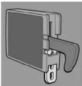
natural_image
Technical illustration of a mechanical component with a handle and mounting bracket (no text or symbols)Fig. 28
Fig. 29
4.11 Illuminazione
natural_image
Mechanical assembly diagram showing a clamping mechanism with rotating components (no text or symbols)Fig. 30

natural_image
Diagram of a metal rack structure with an arrow pointing to it, no text or symbols presentFig. 31
text_image
Diagram illustrating three steps of a door or shelf installation: opening, pressing down, and cooling.Fig. 32
text_image
Diagram showing a mechanical component with labeled parts and directional arrow, likely illustrating a process or assembly.Fig. 34Fig.
natural_image
Diagram of a ventilation grille with numbered components (1 and 2), no text or symbols presentnatural_image
Illustration of a hand using a pipette to lift a grid of cubes (no text or symbols visible)Fig. 38
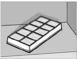
natural_image
3D illustration of a rectangular block with a grid pattern, placed on a flat surface (no text or symbols)Fig. 39
natural_image
Mechanical component with a black arrow pointing to a specific part (no text or symbols visible)Fig. 42

natural_image
Pure mechanical assembly diagram showing a piston-like component inserted into a housing (no text or symbols)Fig. 43
text_image
Diagram illustrating mechanical assembly or cutting process with arrows and checkmark annotationsFig. 46
natural_image
Technical diagram of a mechanical assembly with arrows indicating motion or force direction (no text or symbols)Fig. 47

text_image
Technical diagram showing two views of a door frame with directional arrows indicating movement or force, labeled 2 and 3.Fig. 48 Fig. 49

natural_image
Technical diagram showing a corner joint with two downward arrows indicating force or direction (no text or symbols present)Fig. 50
natural_image
Line drawing of a white refrigerator with control panel and door (no text or symbols)Type C40 / 110
CE

10 R - 047358
N4
MBA 12/2014
NL

Voor uw veiligheid

WAARSCHUWING!
DECLARATION OF CONFORMITY
according to
Low Voltage Directive 73/23/EEC and
the Amendment to LVD 2006/95/EC
EMC Directive 2004/108/EC
Automotive Directive 72/245/EEC and
the Amendment 95/54/EC, 2009/19/EC
Gas Appliance Directive 2009/142/EC
End-of-Life Vehicle Directive 2000/53/EC
RoHS Directive 2002/95/EC
Type of equipment
Brand Name
Type family
Manufacturer's (Factory)
name
address
telephone no
telefax no
Absorption Refrigerator
DOMETIC
C 40/110
DOMETIC GmbH
The following harmonized standards or technical specifications (designations) which comply with good engineering practice in safety matters in force within the EEA have been practiced:
EN 60335-1;02. (IEC 60335-1; 4 ed., Am. 1, Am. 2),
EN 60335-2-24:03 (IEC 60335-2-24; 6 ed., Am. 1, Am. 2)
EN 61000-3-2;00, A1, A2, A14 EN 61000-3-3;95, A1,
EN 55014-1:07. A1. A2 EN 55014-2:01. A1
The equipment conforms completely with the above stated harmonized standards or technical specifications.
By signing this document, the undersigned declares as manufacturer, or the manufacturer's authorized representative established within the EEA, that the equipment in question complices with the requirements stated above.
Date
2012.01.04
Position
General Manager

natural_image
Technical line drawing of a refrigerant appliance with no visible text or symbols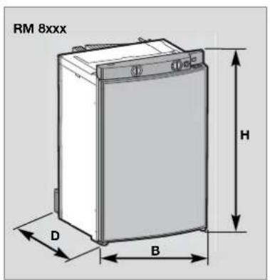
text_image
RM 8xxx H D BAfb. 2
Afb. 3

natural_image
Illustration of a RML 8xx6 refrigerant cabinet (no text or symbols on the cabinet body)Afb. 4
Technische gegevens / modellen met gebogen deur
| Model Afmetingen Bruto inhoudH x B x D (mm) incl/zonder net/accu stroom/gas gewicht piëzo diepte incl. deur vriesvak vriesvak in 24h maat | Aansluitwaarden | Verbruik * Netto- Ontsteking auto- | |||||
| RMS 8400 | 821x486x568 | 80 / 85 lit. | 8 lit. | 125 W / 120 W | ca.2,5 KWh / 270 g | 25 kg | • |
| RMS 8401 | 821x486x568 | 80 / 85 lit. | 8 lit. | 125 W / 120 W | ca.2,5 KWh / 270 g | 25 kg | |
| RMS 8405 | 821x486x568 | 80 / 85 lit. | 8 lit. | 125 W / 120 W | ca.2,5 KWh / 270 g | 25 kg | |
| RM 8400 | 821x486x568 | 90 / 95 lit. | 8 lit. | 135 W / 130 W | ca.2,4 KWh / 270 g | 27 kg | • |
| RM 8401 | 821x486x568 | 90 / 95 lit. | 8 lit. | 135 W / 130 W | ca.2,4 KWh / 270 g | 27 kg | |
| RM 8405 | 821x486x568 | 90 / 95 lit. | 8 lit. | 135 W / 130 W | ca.2,4 KWh / 270 g | 27 kg | |
| RMS 8460 | 821x486x633 | 90 / 96 lit. | 11 lit. | 125 W / 120 W | ca.2,5 KWh / 270 g | 26 kg | • |
| RMS 8461 | 821x486x633 | 90 / 96 lit. | 11 lit. | 125 W / 120 W | ca.2,5 KWh / 270 g | 26 kg | |
| RMS 8465 | 821x486x633 | 90 / 96 lit. | 11 lit. | 125 W / 120 W | ca.2,5 KWh / 270 g | 26 kg | |
| RMS 8500 | 821x523x568 | 90 / 96 lit. | 9 lit. | 125 W / 120 W | ca.2,5 KWh / 270 g | 26 kg | • |
| RMS 8501 | 821x523x568 | 90 / 96 lit. | 9 lit. | 125 W / 120 W | ca.2,5 KWh / 270 g | 26 kg | |
| RMS 8505 | 821x523x568 | 90 / 96 lit. | 9 lit. | 125 W / 120 W | ca.2,5 KWh / 270 g | 26 kg | |
| RMS 8550 | 821x523x623 | 103/110 lit. | 12 lit. | 125 W / 120 W | ca.2,6 KWh / 270 g | 27 kg | • |
| RMS 8551 | 821x523x623 | 103/110 lit. | 12 lit. | 125 W / 120 W | ca.2,6 KWh / 270 g | 27 kg | |
| RMS 8555 | 821x523x623 | 103/110 lit. | 12 lit. | 125 W / 120 W | ca.2,6 KWh / 270 g | 27 kg | |
| RM 8500 | 821x523x568 | 100/106 lit. | 9 lit. | 135 W / 130 W | ca.2,4 KWh / 270 g | 28 kg | • |
| RM 8501 | 821x523x568 | 100/106 lit. | 9 lit. | 135 W / 130 W | ca.2,4 KWh / 270 g | 28 kg | |
| RM 8505 | 821x523x568 | 100/106 lit. | 9 lit. | 135 W / 130 W | ca.2,4 KWh / 270 g | 28 kg | |
| RM 8550 | 821x523x623 | 115/122 lit. | 12 lit. | 135 W / 130 W | ca.2,6 KWh / 270 g | 30 kg | • |
| RM 8551 | 821x523x623 | 115/122 lit. | 12 lit. | 135 W / 130 W | ca.2,6 KWh / 270 g | 30 kg | |
| RM 8555 | 821x523x623 | 115/122 lit. | 12 lit. | 135 W / 130 W | ca.2,6 KWh / 270 g | 30 kg | |
| RML 8550 | 1245x523x625 | 179/189 lit. | 33 lit. | 190 W / 170 W | ca.3,2 KWh / 380 g | 45 kg | • |
| RML 8551 | 1245x523x625 | 179/189 lit. | 33 lit. | 190 W / 170 W | ca.3,2 KWh / 380 g | 45 kg | |
| RML 8555 | 1245x523x625 | 179/189 lit. | 33 lit. | 190 W / 170 W | ca.3,2 KWh / 380 g | 45 kg | |
| RMSL 8500 | 1245x523x568 | 145/155 lit. | 28 lit. | 190 W / 170 W | ca.3,2 KWh / 380 g | 40 kg | • |
| RMSL 8501 | 1245x523x568 | 145/155 lit. | 28 lit. | 190 W / 170 W | ca.3,2 KWh / 380 g | 40 kg | |
| RMSL 8505 | 1245x523x568 | 145/155 lit. | 28 lit. | 190 W / 170 W | ca.3,2 KWh / 380 g | 40 kg | |
text_image
Diagram showing four labeled circular components with numbered annotations, likely illustrating a control or measurement setup.Afb. 7
text_image
Diagram showing a hand pressing down on a circular dial with labeled buttons 2, 3, and 4, alongside a droplet symbol.Afb. 14
text_image
Domestic 1Batterijvak
Afb. 21

natural_image
Diagram showing a kitchen sink with a water drop and two circular fixtures on a tray (no text or symbols)Afb. 24

natural_image
Simple line drawing of a room corner with a curved door and window (no text or symbols)Afb. 25
natural_image
Mechanical component diagram showing a bracket with a handle and a pull arrow (no text or symbols)Vastzetten

natural_image
Illustration of a mechanical device with a handle and internal components (no text or symbols)Afb. 26
Afb. 27

natural_image
Diagram of a mechanical component with a downward arrow indicating force or direction (no text or symbols present)Losmaken

natural_image
Technical illustration of a mechanical component with a handle and mounting bracket (no text or symbols)Afb. 28
Afb. 29
4.11 Verlichting
natural_image
Mechanical assembly diagram showing a piston-like component with motion indicators (no text or symbols)Afb. 30

natural_image
Diagram of a metal rack structure with an arrow pointing to it, no text or symbols presentAfb. 31
text_image
Diagram illustrating three steps of a door latch mechanism: opening, lifting, and cooling a grater.Afb. 32
text_image
Technical diagram showing a mechanical component with labeled parts and directional arrow indicating motion or forceAfb. 34Afb.
natural_image
Illustration of a hand using a pipette to process a 3x4 grid-patterned tray (no text or symbols visible)Afb. 38

natural_image
3D illustration of a rectangular block with a grid pattern on top, placed on a flat surface (no text or symbols)Afb. 39
natural_image
Mechanical component with a black arrow pointing to a section detail (no visible text or symbols)Afb. 42

natural_image
Pure mechanical assembly diagram showing a piston-like component with a black arrow indicating direction (no text or symbols)Afb. 43
natural_image
Technical diagram of a mechanical assembly with arrows indicating motion or force direction (no text or symbols present)Afb. 47
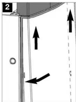
text_image
2 16Afb. 48 Afb. 49
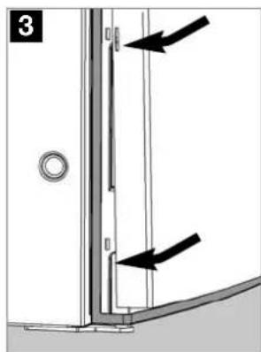
natural_image
Diagram of a door frame with two arrows pointing to vertical and horizontal components (no text or symbols)
natural_image
Technical diagram showing a corner joint with two downward arrows indicating force or direction (no text or symbols present)Afb. 50
natural_image
Line drawing of a white refrigerator with control panel and door (no text or symbols)Type C40 / 110
CE
E _1
10 R - 047358
N4
MBA 12/2014
DA

For din sikkerhed

ADVARSEL!
text_image
Dometic GROUP DECLARATION OF CONFORMITY according to Low Voltage Directive 73/23/EEC and the Amendment to LVD 2006/95/EC EMC Directive 2004/108/EC Automotive Directive 72/245/EEC and the Amendment 95/54/EC, 2009/19/EC Gas Appliance Directive 2009/142/EC End-of-Life Vehicle Directive 2000/53/EC RoHS Directive 2002/95/EC Type of equipment Absorption Refrigerator Brand Name DOMETIC Type family C 40/110 Manufacturer's (Factory) name DOMETIC GmbH address In der Steinwiese 16, D-57074 Siegen telephone no INT+49 -271 692 0 telefax no INT+49 -271 692 304 The following harmonized standards or technical specifications (designations) which comply with good engineering practice in safety matters in force within the EEA have been practiced: EN 60335-1:02. (IEC 60335-1; 4 ed., Am. 1. Am. 2), EN 60335-2-24:03 (IEC 60335-2-24; 6 ed., Am. 1. Am. 2) EN 61000-3-2:00, A1, A2, A14 EN 61000-3-3:95, A1, EN 55014-1:07, A1, A2 EN 55014-2:01, A1 EN 732:98 EN 60335-2-102:06 EN 624:00 (LSC-Models) EN 10 -1-1:08 (Tectower-Models) EN 10-2-1; 98 A1, A2 (Tectower-Models) The equipment conforms completely with the above stated harmonized standards or technical specifications. By signing this document, the undersigned declares as manufacturer, or the manufacturer's authorized representative established within the EEA, that the equipment is question complies with the requirements stated above. Date Signature Position 2012.01.04 Dr.Michael Freitag General Manager
natural_image
Line drawing of a refrigerant appliance with no visible text or symbols on the device itself
text_image
RM 8xxx D B HAfb. 3Afb. 2

natural_image
Line drawing of a RML 8xxx battery casing (no text or symbols on the diagram itself)Afb. 4
text_image
Diagram showing four labeled circular components with numbered annotations, likely illustrating a control or measurement setup.Afb. 7
text_image
Diagram showing hand press control buttons labeled 2, 3, and 4 for industrial automation or cleaning processAfb. 14
text_image
Domestic 1Batterifag
Afb. 21

text_image
Dometic tryknatural_image
Diagram showing a kitchen sink with a water drop and two circular fixtures on a tray (no text or symbols)Afb. 24

natural_image
Interior view of a room with a curved door and wall-mounted window (no text or symbols visible)Afb. 25
natural_image
Diagram of a mechanical component with an arrow indicating direction (no text or symbols present)Fiksering

natural_image
Illustration of a mechanical device with a handle and internal components (no text or symbols)Afb. 26
Afb. 27
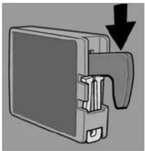
natural_image
Diagram of a mechanical component with a downward arrow indicating force or direction (no text or symbols present)løsnen

natural_image
Technical illustration of a mechanical component with a handle and mounting bracket (no text or symbols)Afb. 28
Afb. 29
4.11 Belysning
natural_image
Mechanical assembly diagram showing a piston-like component with motion arrows and mounting holes (no text or symbols)Afb. 30

natural_image
Diagram of a metal grid structure with an arrow pointing to it, no text or symbols presentAfb. 31
text_image
Diagram showing a mechanical component with labeled parts and directional arrow, likely illustrating a motion or assembly process.Afb. 34
natural_image
Illustration of a hand using a pipette to process a 3x4 grid-patterned tray (no text or symbols visible)Afb. 38

natural_image
3D illustration of a rectangular block with a grid pattern, placed on a flat surface (no text or symbols)Afb. 39
natural_image
Mechanical component with a black arrow pointing to a specific part (no text or symbols visible)Afb. 42

natural_image
Pure mechanical assembly diagram showing a piston-like component with a black arrow indicating direction (no text or symbols)Afb. 43
text_image
FORSIGTIG!Afb. 46
natural_image
Technical diagram of a mechanical assembly with arrows indicating motion or force direction (no text or symbols)Afb. 47

text_image
2 16Afb. 48 Afb. 49

natural_image
Diagram of a door frame with two arrows pointing to vertical and horizontal components (no text or symbols)
natural_image
Technical diagram showing a corner joint with two downward arrows indicating force or direction (no text or symbols present)Afb. 50
natural_image
Line drawing of a white refrigerator with control panel and door (no text or symbols)Type C40 / 110
CE
E _1
10 R - 047358
N 4
MBA 12/2014
SV

För din säkerhet

WARNING!
text_image
Dometic GROUP DECLARATION OF CONFORMITY according to Low Voltage Directive 73/23/EEC and the Amendment to LVD 2006/95/EC EMC Directive 2004/108/EC Automotive Directive 72/245/EEC and the Amendment 95/54/EC, 2009/19/EC Gas Appliance Directive 2009/142/EC End-of-Life Vehicle Directive 2000/53/EC RoHS Directive 2002/95/EC Type of equipment Absorption Refrigerator Brand Name DOMETIC Type family C 40/110 Manufacturer's (Factory) name DOMETIC GmbH address In der Steinwiese 16, D-57074 Siegen telephone no INT+49 -271 692 0 telefax no INT+49 -271 692 304 The following harmonized standards or technical specifications (designations) which comply with good engineering practice in safety matters in force within the EEA have been practiced: EN 60335-1:02. (IEC 60335-1; 4 ed., Am. 1. Am. 2), EN 60335-2-24:03 (IEC 60335-2-24; 6 ed., Am. 1. Am. 2) EN 61000-3-2:00, A1, A2, A14 EN 61000-3-3:95, A1, EN 55014-1:07, A1, A2 EN 55014-2:01, A1 EN 732:98 EN 60335-2-102:06 EN 624:00 (LSC-Models) EN 10 -1-1:08 (Tectower-Models) EN 10-2-1; 98 A1, A2 (Tectower-Models) The equipment conforms completely with the above stated harmonized standards or technical specifications. By signing this document, the undersigned declares as manufacturer, or the manufacturer's authorized representative established within the EEA, that the equipment is question complies with the requirements stated above. Date Signature Position 2012.01.04 Dr.Michael Freitag General Manager
natural_image
Line drawing of a refrigerant appliance with front panel and side door (no text or symbols)
text_image
RM 8xxx D B H
natural_image
Line drawing of a RML 8xxx battery casing (no text or symbols on the diagram itself)Avb. 3Avb. 2
Avb. 4
text_image
Diagram showing four labeled circular components with numbered annotations, likely illustrating a control or measurement setup.Avb. 7
text_image
Diagram showing finger pressing a circular component with numbered labels 2, 3, and 4, alongside a droplet symbol.Avb. 14
text_image
① I ② ③ - + ④ AAvb. 19
text_image
Domestic 1Batterifack
Avb. 21

Batterier ingår ej.
Sätt i batterier (8 x AA 1.5 V) i batterifacket innan kylskåpet tas i drift.
Autark gasdrift
text_image
Dometic tryckÖppna batterifacket
Avb. 22
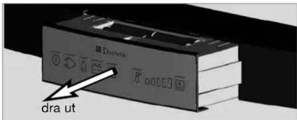
text_image
Domestic dra utDra ut batterifacket
Avb. 23
SE UPP!
natural_image
Diagram showing a kitchen sink with a water drop and two circular fixtures on a tray (no text or symbols)Avb. 24

natural_image
Simple line drawing of a room corner with a curved door and window (no text or symbols)Avb. 25
natural_image
Mechanical component diagram showing a bracket with a handle and arrow indicating direction (no text or symbols)Fixera
Avb. 26

natural_image
Illustration of a mechanical device with a handle and internal components (no text or symbols)Avb. 27

natural_image
Diagram of a mechanical component with a downward arrow indicating force or direction (no text or symbols present)Lossa

natural_image
Technical illustration of a mechanical component with a handle and mounting bracket (no text or symbols)Avb. 28
Avb. 29
4.11 Belysning
natural_image
Mechanical assembly diagram showing a piston-like component with rotating springs and housing (no text or symbols)Avb. 30

natural_image
Diagram of a metal rack structure with an arrow pointing to it, no text or symbols presentAvb. 31
text_image
Diagram showing a mechanical component with labeled parts and directional arrow, likely illustrating a motion or assembly process.Avb. 34
natural_image
Illustration of a hand using a pipette to process a grid-patterned tray (no text or symbols visible)natural_image
3D illustration of a rectangular block with grid pattern, placed on a surface (no text or symbols)- Placera islådan i frostfacket.
natural_image
Mechanical component with a black arrow pointing to a specific part (no visible text or symbols)Avb. 42

natural_image
Pure mechanical assembly diagram showing a piston-like component with a black arrow indicating direction (no text or symbols)Avb. 43
text_image
3 2 1 A A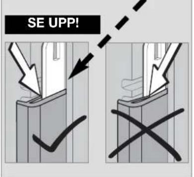
text_image
SE UPP!Avb. 46
natural_image
Technical diagram of a mechanical assembly with arrows indicating motion or force direction (no text or symbols present)Avb. 47
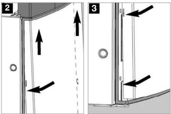
text_image
Technical diagram showing two mechanical assembly steps with directional arrows and labeled componentsAvb. 48 Avb. 49

natural_image
Diagram of a door corner with two arrows indicating downward force or movement (no text or symbols present)Avb. 50
natural_image
Line drawing of a white refrigerator with control panel and door (no text or symbols)Type C40 / 110
CE
E _1
10 R - 047358
N4
MBA 12/2014
NO

For din sikkerhet

ADVARSEL!
text_image
Dometic GROUP DECLARATION OF CONFORMITY according to Low Voltage Directive 73/23/EEC and the Amendment to LVD 2006/95/EC EMC Directive 2004/108/EC Automotive Directive 72/245/EEC and the Amendment 95/54/EC, 2009/19/EC Gas Appliance Directive 2009/142/EC End-of-Life Vehicle Directive 2000/53/EC RoHS Directive 2002/95/EC Type of equipment Absorption Refrigerator Brand Name DOMETIC Type family C 40/110 Manufacturer's (Factory) name DOMETIC GmbH address In der Steinwiese 16, D-57074 Siegen telephone no INT+49 -271 692 0 telefax no INT+49 -271 692 304 The following harmonized standards or technical specifications (designations) which comply with good engineering practice in safety matters in force within the EEA have been practiced: EN 60335-1:02. (IEC 60335-1; 4 ed., Am. 1. Am. 2), EN 60335-2-24:03 (IEC 60335-2-24; 6 ed., Am. 1. Am. 2) EN 61000-3-2:00, A1, A2, A14 EN 61000-3-3:95, A1, EN 55014-1:07, A1, A2 EN 55014-2:01, A1 EN 732:98 EN 60335-2-102:06 EN 624:00 (LSC-Models) EN 10 -1-1:08 (Tectower-Models) EN 10-2-1; 98 A1, A2 (Tectower-Models) The equipment conforms completely with the above stated harmonized standards or technical specifications. By signing this document, the undersigned declares as manufacturer, or the manufacturer's authorized representative established within the EEA, that the equipment is question complies with the requirements stated above. Date Signature Position 2012.01.04 Dr.Michael Freitag General Manager
natural_image
Technical line drawing of a refrigerant appliance with no visible text or symbols
text_image
RM 8xxx H D B
natural_image
Line drawing of a RML 8xxx battery casing (no text or symbols on the diagram itself)Avb. 3Avb. 2
Avb. 4
text_image
Diagram showing four labeled circular components with numbered annotations, likely illustrating a control or measurement setup.Avb. 7
Manuelt energivalg / automatisk tenning MES (RM 8xx1) :
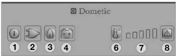
text_image
Dometic 1 2 3 4 6 7 8Avb. 8
text_image
Diagram showing hand press control buttons labeled 2, 3, and 4 for a device operationAvb. 14
text_image
Domestic 1Batterirom
Avb. 21

text_image
Dometic trykk innnatural_image
Diagram showing a water level sensor with liquid drop and two circular components on a base (no text or symbols)Avb. 24

natural_image
Simple line drawing of a room corner with a curved door and window (no text or symbols)Avb. 25
natural_image
Diagram of a mechanical component with an arrow indicating direction (no text or symbols present)Sperring

natural_image
Illustration of a mechanical device with a handle and internal components (no text or symbols)Avb. 26
Avb. 27

natural_image
Diagram of a mechanical component with a downward arrow indicating force or direction (no text or symbols present)Frigivelse
Avb. 28
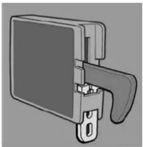
natural_image
Technical illustration of a mechanical component with a handle and mounting bracket (no text or symbols)Avb. 29
4.11 Belysning
Den innvendige belysningen styres via en dør- kontakt. Hvis døren blir stående åpen lenger enn 2 minutter, lyder et akustisk varselsignal (en pulserende pipetone).
natural_image
Mechanical assembly diagram showing a piston-like component with rotating springs and housing (no text or symbols)Avb. 30

natural_image
Diagram of a metal grid structure with an arrow pointing to it, no text or symbols presentAvb. 31
text_image
Diagram showing a mechanical component with labeled parts and directional arrow, likely illustrating a motion or assembly process.Avb. 34Avb.
natural_image
Illustration of a hand using a pipette to lift a grid of cubes (no text or symbols visible)Avb. 38
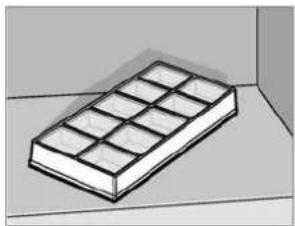
natural_image
3D illustration of a rectangular block with grid pattern on top, placed on a flat surface (no text or symbols)Avb. 39
natural_image
Mechanical component with a black arrow pointing to a specific part (no text or symbols visible)Avb. 42

natural_image
Mechanical assembly diagram showing a component with a black arrow indicating direction (no text or symbols present)Avb. 43
natural_image
Technical diagram of a mechanical assembly with arrows indicating motion or force direction (no text or symbols)Avb. 47
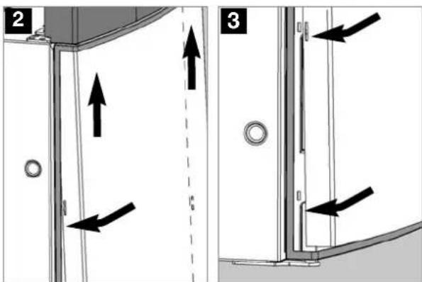
text_image
Technical diagram showing two views of a door frame with directional arrows and alignment markers, labeled 2 and 3.Avb. 48 Avb. 49
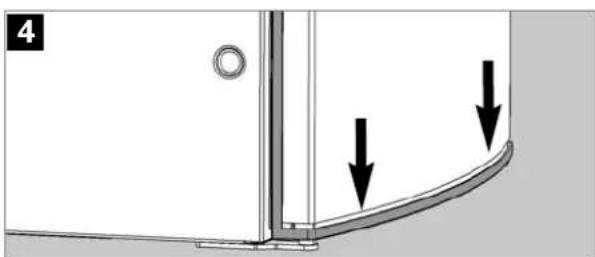
natural_image
Technical diagram showing a corner joint with two downward arrows indicating force or direction (no text or symbols present)Avb. 50
natural_image
Line drawing of a white refrigerator with control panel and door (no text or symbols)Type C40 / 110
CE

10 R - 047358
N4
MBA 12/2014
FI
Turvallisuusohjeet

VAROITUS!
DECLARATION OF CONFORMITY
according to
Low Voltage Directive 73/23/EEC and the Amendment to LVD 2006/95/EC EMC Directive: 2004/108/EC Automotive Directive 72/245/EEC and the Amendment 95/54/EC, 2009/19/EC Gas Appliance Directive 2009/142/EC End-of-Life Vehicle Directive 2000/53/EC RoHS Directive 2002/95/EC
| Type of equipment | Absorption Refrigerator |
| Brand Name | DOMETIC |
| Type family | C 40/110 |
| Manufacturer* s (Factory) | |
| name | DOMETIC GmbH |
| address | In der Steinwiese 16, D-57074 Siegen |
| telephone no | INT+49 - 271 692 0 |
| telefax no | INT+49 - 271 692 304 |
| The following harmonized standards or technical specifications (designations) which comply with good engineering practice in safety matters in force within the EEA have been practiced: | |
| EN 60335-1;02, (IEC 60335-1; 4 ed., Am. 1, Am. 2), | |
| EN 60335-2-24:03 (IEC 60335-2-24; 6 ed., Am. 1, Am. 2) | |
| EN 61000-3-2;90, A1, A2, A14 | EN 61000-3-3;95, A1, |
| EN 55014-1:07, A1, A2 | EN 55014-2:01, A1 |
| EN 732;98 | EN 60335-2-102;06 EN 624;00 (LSC-Models) |
| EN 10 -1-1;08 (Tectower-Models) | |
| EN 30-2-1; 98 A1, A2 (Tectower-Models) | |
The equipment conforms completely with the above stated harmonized standards or technical specifications.
By signing this document, the undersigned declares as manufacturer, or the manufacturer's authorized representative established within the EEA, that the equipment in question complices with the requirements stated above.
Date
2012.01.04
Position
General Manager

natural_image
Line drawing of a refrigerant appliance with no visible text or symbols on the device itself
text_image
RM 8xxx S L K
natural_image
Line drawing of a RML 8xxx battery casing (no text or symbols on the diagram itself)kuva 3kuva 2
kuva 4
text_image
Diagram showing four labeled circular components with numbered annotations, likely illustrating a control or measurement setup.kuva 7
text_image
Diagram showing hand press control buttons labeled 2, 3, and 4 for a device operationkuva 14
text_image
Domestic 1text_image
Dometic painanatural_image
Diagram showing a kitchen sink with a water drop and two circular fixtures on a tray (no text or symbols)kuva 24

natural_image
Simple line drawing of a room corner with a curved door and window (no text or symbols)kuva 25
natural_image
Diagram of a mechanical component with an arrow indicating direction (no text or symbols present)natural_image
Illustration of a mechanical device with a handle and internal components (no text or symbols)kuva 27

natural_image
Diagram of a mechanical component with a downward arrow indicating force or direction (no text or symbols present)natural_image
Technical illustration of a mechanical component with a handle and mounting bracket (no text or symbols)kuva 29
4.11 Valaistus
natural_image
Mechanical assembly diagram showing a piston-like component with motion lines and mounting holes (no text or symbols)kuva 30

natural_image
Diagram of a metal grid structure with an arrow pointing to it, no text or symbols presentkuva 31
text_image
Diagram showing a mechanical component with labeled parts and directional arrow, likely illustrating a motion or assembly process.kuva 34
natural_image
Illustration of a hand using a pipette to process a 3x4 grid-patterned tray (no text or symbols visible)kuva 38

natural_image
3D illustration of a rectangular block with a grid pattern on top, placed on a flat surface (no text or symbols)kuva 39
natural_image
Mechanical component with a black arrow pointing to a specific part (no text or symbols visible)kuva 42
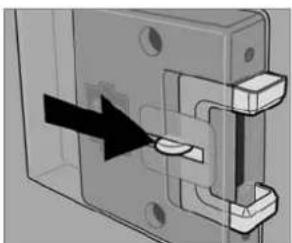
natural_image
Pure mechanical assembly diagram showing a piston-like component with a black arrow indicating direction (no text or symbols)kuva 43
natural_image
Technical diagram of a mechanical assembly with arrows indicating motion or force direction (no text or symbols present)kuva 47
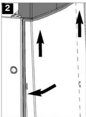
text_image
2 16
natural_image
Diagram of a door frame with two arrows pointing to vertical and horizontal components (no text or symbols)kuva 48 kuva 49

natural_image
Technical diagram showing a corner joint with two downward arrows indicating force or direction (no text or symbols present)kuva 50
4.20 Vianetsintä
1 = ON-/OFF-painike
2 = energian valintapainike 230V AC
3 = energian valintapainike GAS
4 = energian valintapainike 12V DC
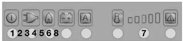
text_image
1 2 3 4 5 6 8 7AES
kuva 52
natural_image
Line drawing of a white refrigerator with control panel and door (no text or symbols)Type C40 / 110
CE

10 R - 047358
N4
MBA 12/2014
PT

Para sua segurança

AVISO!
text_image
Dometic GROUP DECLARATION OF CONFORMITY according to Low Voltage Directive 73/23/EEC and the Amendment to LVD 2006/95/EC EMC Directive 2004/108/EC Automotive Directive 72/245/EEC and the Amendment 95/54/EC, 2009/19/EC Gas Appliance Directive 2009/142/EC End-of-Life Vehicle Directive 2000/53/EC RoHS Directive 2002/95/EC Type of equipment Absorption Refrigerator Brand Name DOMETIC Type family C 40/110 Manufacturer* s (Factory) name DOMETIC GmbH address In der Steinwiese 16, D-57074 Siegen telephone no INT+49 - 271 692 0 telefax no INT+49 - 271 692 304 The following harmonized standards or technical specifications (designations) which comply with good engineering practice in safety matters in force within the EEA have been practiced: EN 60335-1:02. (IEC 60335-1; 4 ed., Am. 1. Am. 2), EN 60335-2-24:03 (IEC 60335-2-24; 6 ed., Am. 1. Am. 2) EN 61000-3-2:00, A1, A2, A14 EN 61000-3-3:95, A1, EN 55014-1:07, A1, A2 EN 55014-2:01, A1 EN 732:98 EN 60335-2-102:06 EN 624:00 (LSC-Models) EN 10 -1-1:08 (Tectower-Models) EN 10-2-1; 98 A1, A2 (Tectower-Models) The equipment conforms completely with the above stated harmonized standards or technical specifications. By signing this document, the undersigned declares as manufacturer, or the manufacturer's authorized representative established within the EEA, that the equipment is question complies with the requirements stated above. Date Signature Position 2012.01.04 Dr.Michael Freitag General Manager
natural_image
Technical line drawing of a refrigerant appliance with no visible text or symbols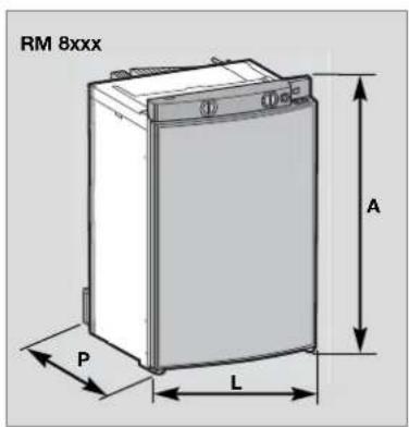
text_image
RM 8xxx A P L
natural_image
Line drawing of a RML 8xxx battery casing (no text or symbols on the diagram itself)text_image
Diagram showing four labeled circular components with numbered annotations, likely illustrating a control or measurement setup.Fig. 7
text_image
Diagram showing two circular gauges labeled 1 and 2, with arrows indicating direction of movement or change.Fig. 12
text_image
Diagram showing hand press control buttons labeled 2, 3, and 4 for a device operationFig. 14
text_image
Domestic 1text_image
Dometic pressionarnatural_image
Diagram showing a kitchen sink with a water drop and two circular fixtures on a tray (no text or symbols)Fig. 24
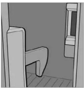
natural_image
Simple line drawing of a room corner with a curved door and window (no text or symbols)Fig. 25
Abrir a porta girando a tecla de trava e puxar (ver a fig. 24).
natural_image
Diagram of a mechanical component with an arrow indicating upward motion (no text or symbols present)Fixar
Fig. 26

natural_image
Illustration of a mechanical device with a handle and internal components (no text or symbols)Fig. 27

natural_image
Diagram of a mechanical component with a downward arrow indicating force or direction (no text or symbols present)Soltar

natural_image
Technical illustration of a mechanical component with a handle and mounting bracket (no text or symbols)Fig. 28
Fig. 29
4.11 Iluminação
natural_image
Mechanical assembly diagram showing a piston-like component with rotating springs and housing (no text or symbols)Fig. 30

natural_image
Diagram of a metal grid structure with an arrow pointing to it, no text or symbols presentFig. 31
text_image
Diagram illustrating three steps of a door latch mechanism: opening, lifting, and cooling a grater.Fig. 32
text_image
Technical diagram showing a mechanical component with labeled parts and directional arrow indicating motion or forceFig. 34
natural_image
Diagram of a ventilation grille with numbered components (1 and 2), no text or symbols presentnatural_image
Illustration of a hand using a pipette to process a grid-patterned tray (no text or symbols visible)Fig. 38
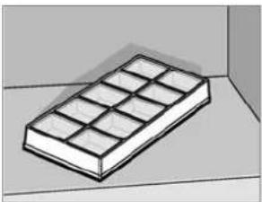
natural_image
3D illustration of a rectangular block with internal grid pattern, placed on a flat surface (no text or symbols)Fig. 39
natural_image
Mechanical component with a black arrow pointing to a specific part (no text or symbols visible)Fig. 42

natural_image
Pure mechanical assembly diagram showing a piston and housing component without any text or symbolsFig. 43
natural_image
Technical diagram of a mechanical assembly with arrows indicating motion or force direction (no text or symbols)Fig. 47

text_image
2 16Fig. 48 Fig. 49

natural_image
Diagram of a door frame with two arrows indicating directional movement (no text or symbols)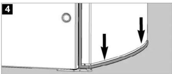
natural_image
Technical diagram showing a corner joint with two downward arrows indicating force or direction (no text or symbols present)Fig. 50