
S.3way - Hi-fi system SAMSON - Free user manual and instructions
Find the device manual for free S.3way SAMSON in PDF.
| Product Type | 3-way electronic active crossover for sound reinforcement system |
| Brand | Samson |
| Model | S.3way |
| Category | Hi-fi system (active crossover filter) |
| Operating modes | 2-way stereo, 3-way stereo, 4-way mono, 4-way LOW (subwoofer) |
| Filter type | Linkwitz-Riley 24 dB/octave, high precision |
| High-pass filter | Butterworth 25 Hz, 12 dB/octave, switchable |
| Adjustable delay | 0 to 2 ms for time alignment of speaker stacks |
| Inputs and outputs | Electronically balanced on XLR connectors |
| Per-band controls | Gain, Mute, phase inversion (180°), limiter |
| CD EQ function | Special equalization for constant directivity horns (softens high frequencies) |
| Mono Sub function | Sums the low-frequency signals of both inputs for mono subwoofer output |
| Limiter | Multiband, adjustable threshold from -5 dB to +18 dB, with Peak indicator |
| Display | 4-segment input level meters, mode and limiter indicators |
| Potentiometers | Detented 41-position, high quality |
| Front panel | Electric blue anodized steel, backlit |
| Rack mounting | 19 inches, with mounting brackets |
| Power supply | Mains via standard IEC connector, external fuse |
| Warranty | 3 years |
| Dimensions (approx.) | 48.3 x 4.4 x 20 cm (width x height x depth) for 1U rack |
| Weight (approx.) | 5.5 kg |
| Maintenance and cleaning | Disconnect the device before cleaning. Use a soft, dry cloth. Do not use abrasive products or solvents. |
| Safety instructions | Observe the power on/off sequence: amplifiers last to power on, first to power off. Do not expose to moisture. |
| Spare parts and repairability | Contact Samson customer service for any repairs. Use only original parts. |
Frequently Asked Questions - S.3way SAMSON
User questions about S.3way SAMSON
0 question about this device. Answer the ones you know or ask your own.
Ask a new question about this device
Download the instructions for your Hi-fi system in PDF format for free! Find your manual S.3way - SAMSON and take your electronic device back in hand. On this page are published all the documents necessary for the use of your device. S.3way by SAMSON.
USER MANUAL S.3way SAMSON
STEREO/MONO CROSSOVER
Owners Manual
SAMSON®
Safety Instructions
Caution: To reduce the hazard of electrical shock, do not remove cover or back.
No user serviceable parts inside. Please refer all servicing to qualified personnel.
CAUTION
FOR CONTINUED PROTECTION AGAINST RISK OF FIRE, REPLACE ONLY WITH SAME TYPE FUSE
ATTENTION
UTILISER UN FUSIBLE DE
RECHANGE DE MÊME TYPE
WARNING
DO NOT EXPOSE THIS EQUIPMENT
TO RAIN OR MOISTURE
AVIS
RISQUE DE CHOC ELECTRONIQUE
NE PAS OUVRIR


WARNING: To reduce the risk of fire or electric shock, do not expose this unit to rain or moisture.
The lightning flash with an arrowhead symbol within an equilateral triangle, is intended to alert the user to the presence of uninsulated "dangerous voltage" within the products enclosure that may be of sufficient magnitude to constitute a risk of electric shock to persons.
The exclamation point within an equilateral triangle is intended to alert the user to the presence of important operating and maintenance (servicing) instructions in the literature accompanying the product.
Important Safety Instructions
-
Please read all instructions before operating the unit.
-
Keep these instructions for future reference.
-
Please heed all safety warnings.
-
Follow manufacturers instructions.
-
Do not use this unit near water or moisture.
-
Clean only with a damp cloth.
-
Do not block any of the ventilation openings. Install in accordance with the manufacturers instructions.
-
Do not install near any heat sources such as radiators, heat registers, stoves, or other apparatus (including amplifiers) that produce heat.
-
Do not defeat the safety purpose of the polarized or grounding-type plug. A polarized plug has two blades with one wider than the other. A grounding type plug has two blades and a third grounding prong. The wide blade or third prong is provided for your safety. When the provided plug does not fit your outlet, consult an electrician for replacement of the obsolete outlet.
-
Protect the power cord from being walked on and pinched particularly at plugs, convenience receptacles and at the point at which they exit from the unit.
-
Unplug this unit during lightning storms or when unused for long periods of time.
-
Refer all servicing to qualified personnel. Servicing is required when the unit has been damaged in any way, such as power supply cord or plug damage, or if liquid has been spilled or objects have fallen into the unit, the unit has been exposed to rain or moisture, does not operate normally, or has been dropped.
Table of Contents
Table des matières Inhalt Contenido
ENGLISH
Introduction 2
S•3-way Features 3
Controls and Functions
Front Panel Layout 4-5
Rear Panel Layout 4-5
Operating the S 3•Way
Setting Up the S•3-way 6
Setting up the S•3-way for Stereo 3-way Operation 7-9
S•3-way Controls 10
S 3•Way System Set-Ups
Stereo 2-way Operation 11
Stereo 3-way Operation 12
Mono 4-way Operation 13
Mono 4-way Low Operation 14
S•3-way Connections 15
Addendum:
Setting up the S•3 way using a Real Time Analyzer 16-17
Specifications 61
Block Diagram 62
FRANÇAIS
Copyright 2001, Samson Technologies Corp.
Printed May, 2001
Samson Technologies Corp.
575 Underhill Blvd.
P.O. Box 9031
Syosset, NY 11791-9031
Phone: 1-800-3-SAMSON (1-800-372-6766)
Fax: 516-364-3888
www.samsontech.com
Introduction
Thank you for purchasing the Samson S•3-way electronic crossover. The Samson S•3-way is a one-space, dual channel electronic crossover capable of managing the frequency control for Stereo 2-Way, Stereo 3-Way, 4-Way Mono and 4-Way Mono Low speaker systems. The S•3-way is an ideal crossover solution for small and large PA systems, live sound venues, commercial installations, recording studio monitors and DJ set-ups. In addition to its flexibility in configuring to different sound systems, the S•3-way has advanced features such as Delay, CD Horn Equalization, dedicated Limiter and individual Phase and Mute switches per frequency band. S•3-way's convenient meters and frequency indicator LEDs provide instant status of important speaker management settings. The S•3-way is a complete electronic crossover solution, which will give you precise control and superior sound from your loudspeaker system.
In these pages, you'll find a detailed description of the features of the S•3-way electronic crossover, as well as a guided tour through its front and rear panels, step-by-step instructions for its setup and use, and full specifications. You'll also find a warranty card enclosed—please don't forget to fill it out and mail it in so that you can receive online technical support and so we can send you updated information about these and other Samson products in the future.
With proper care and adequate air circulation, your S•3-way will operate trouble free for many years. We recommend you record your serial number in the space provided below for future reference.
Serial number:
Date of purchase:
Should your unit ever require servicing, a Return Authorization number (RA) must be obtained before shipping your unit to Samson. Without this number, the unit will not be accepted. Please call Samson at 1-800-3SAMSON (1-800-372-6766) for a Return Authorization number prior to shipping your unit. Please retain the original packing materials and if possible, return the unit in the original carton and packing materials.
S•3-Way Features

The Samson S•3-way electronic crossover utilizes the latest technology in speaker management design. Here are some of its main features:
• Full featured, Stereo 2-way, Stereo 3-way, Mono 4-way electronic crossover.
- Precision Linkwitz-Riley, 24 dB/Octave filters.
• High Pass Filter, Butterworth 25 Hz, 12 dB/Octave.
- Adjustable Low Frequency Delay for time aligning speaker stacks.
- Times 10 Multiplier Switch to adjust frequency range.
- Mode Indicator LED's providing quick visual display of operating mode.
- 4 Segment LED Input Meter allows easy gain adjustment.
- Output Mute switches for all individual outputs.
- Phase Switches invert the phase of the individual outputs.
- Constant Directivity EQ smooths the response of CD horns above 3.5 kHz.
- Mono Sub Switch sums the low frequency signal from both inputs and sends it to both low outputs.
- Peak Limiter with independent Threshold control and Peak LED.
- Advanced circuit design, utilizing low noise operational amplifiers and high quality VCAs.
- Servo balanced inputs and outputs on XLR connectors.
• High quality,41 position detent pots and backlit switches.
- The stylish bead blasted electric blue anodized front-panel is as easy to read as it is to look at.
• Three-year extended warranty.
Controls and Functions
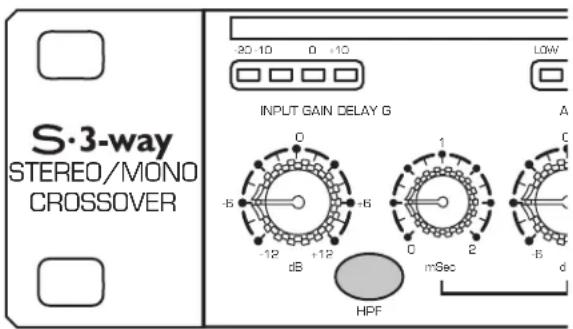
FRONT PANEL LAYOUT
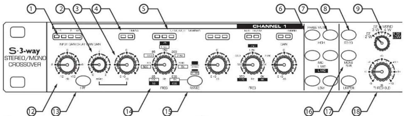
① INPUT METER INDICATORS - 4 LEDS display the amount of level present at the inputs.
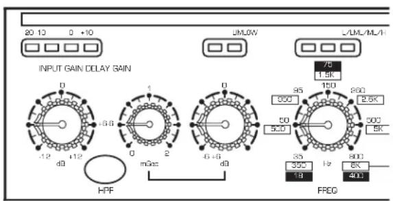
② DELAY - Delay line adjusts from 0 to 2ms for time aligning the low frequency output.
③ GAIN CONTROL - Adjusts the output gain of the individual frequency bands.
④ BAND AND LIMIT INDICATORS - Indicates the bands that are in use depending on the mode selector and indicates when limiting of that band occurs.
⑤CROSSOVER BAND INDICATORS - Indicates the crossover mode that is active depending on the mode selector frequencies.
⑥ PHASE SWITCHES - Used to select in or out of phase operation, individually per frequency band.
⑦MUTE SWITCHES - Individual outputs can be shut completely off with the quick press of a button.
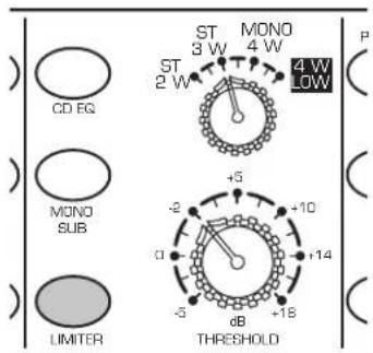
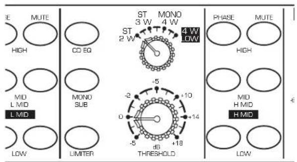
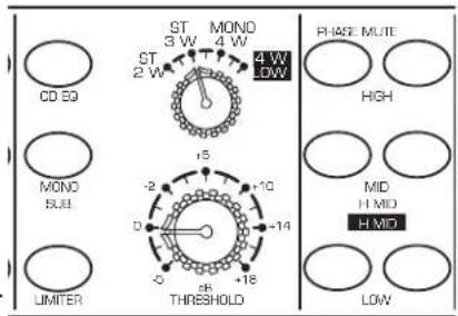
⑧CD EQ - Activates the constant directivity horn EQ curve for smoothing the high frequency response of the sound system.
⑨ OPERATING MODE SELECTOR - Selects one of the 4 operating modes; 2-way stereo, 3-way stereo, 4-way mono and 4-way low.
REAR PANEL LAYOUT
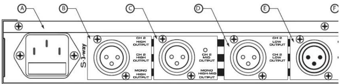
Ⓐ AC INLET - IEC standard ac power cable connector with external fuse.
B CHANNEL 2 HIGH OUTPUT - XLR balanced line output.
©CHANNEL 2 MID OUTPUT - XLR balanced line output.
D CHANNEL 2 LOW OUTPUT - XLR balanced line output.
Controls and Functions
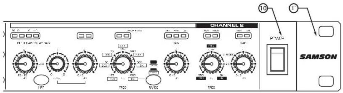
⑩ MAIN POWER SWITCH- When turned on, activates the S·3-way.
⑪ RACK EARS- Used for mounting into a standard 19-inch rack.
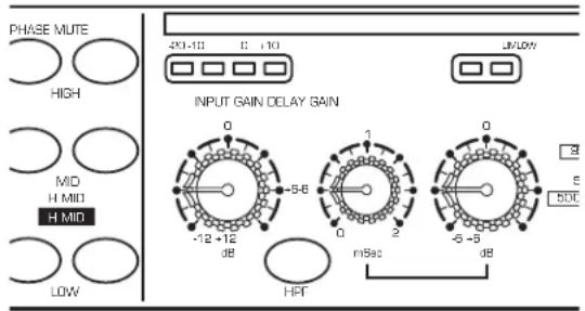
⑫ INPUT GAIN- Used to adjust the input gain from -12dB to +12dB.
⑬ HPF SWITCH- Engages the low frequency roll off at 25Hz.
⑭ FREQUENCY CONTROL- The control that sets the crossover point dividing the frequency bands.
⑮ RANGE SWITCH - Selects the range at which the frequency control operates from normal to times 10.
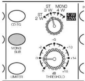
⑯ MONO SUB - Selects mono operation for the sub bass output.
⑰ LIMITER - Built- in peak limiter provides maximum output while offering extended speaker protection.
⑱ THRESHOLD - Adjusts the level of the peak limiter.
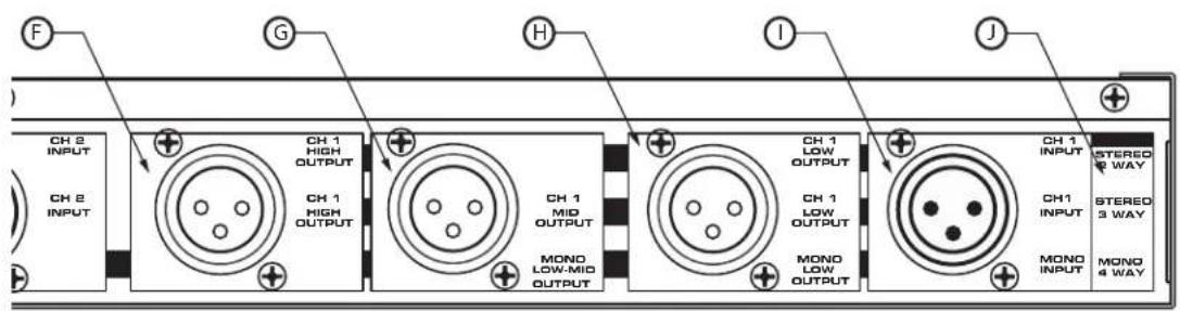
GCHANNEL 1 MID OUTPUT - XLR balanced line output.
H CHANNEL 1 LOW OUTPUT - XLR balanced line output.
① CHANNEL 2 INPUT - XLR balanced line output.
JMODE KEY - Indicates the active outputs in all modes.
Operating the S•3-way
SETTING UP THE S•3-way
Whether you are an experienced audio engineer or just starting out, the next sections of this manual will help you get going with your S•3-way. Now that you have unpacked the unit and have become a bit familiar with the front panel controls, you can follow the next sections of this manual to begin to set-up and operate your new crossover. Further on in this manual, you will find detailed wiring diagrams of various speaker system set-ups.
For detailed diagrams of connector and cable wiring, see page 15 in this manual.
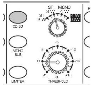
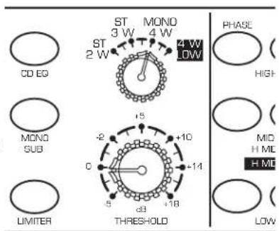
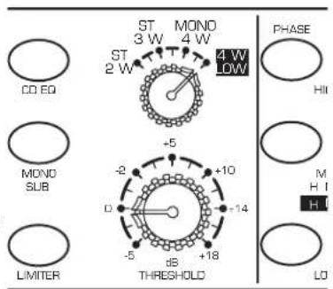
MODE SWITCH
The S•3-way can be configured to operate in several modes including Stereo or Mono 2-way, Stereo or Mono 3-way and Mono 4-way. In addition, the S•3-way has a special operating mode; 4-way LOW which is used for ultra-low sub woofer applications. The Mode Switch, located in the center section of the unit, is used to select the operating mode. As you switch through the various operation modes, you will notice that several LED's on the panel are also changing. These are the Mode Indicator LED's and they help you keep track of the changing controls.
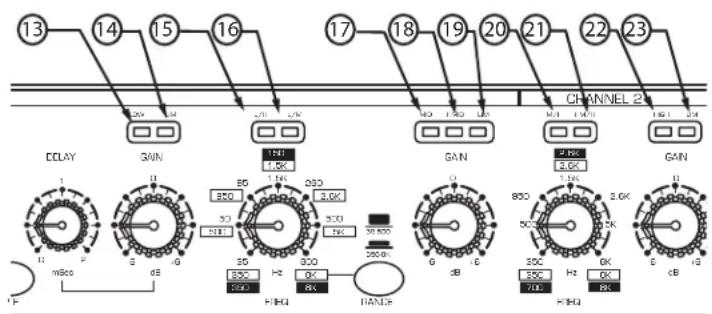
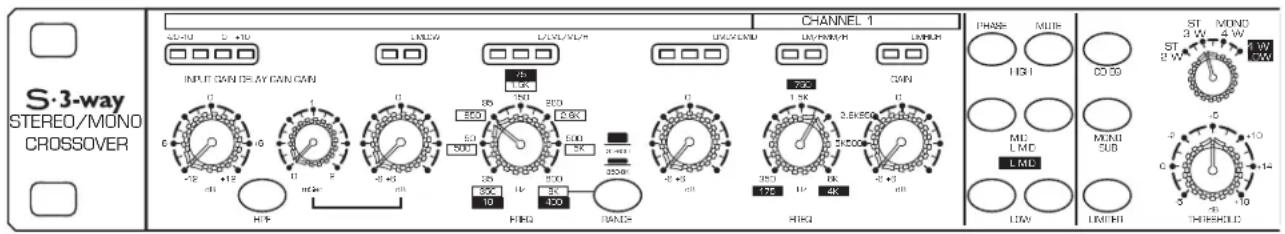
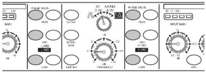
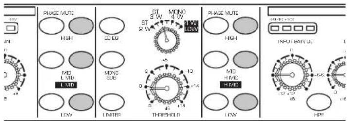
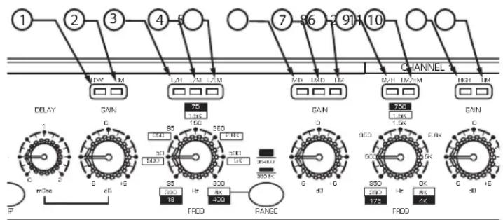
FREQUENCY BAND & LIMIT INDICATORS
Because the S•3-way can be configured to operate in several different size sound systems, the crossover controls may be adjusted for the frequency division between low, and high, or low and low-mid, or high mid to high depending on the mode. On some crossovers, it is very difficult to get a quick visualization as to what controls are controlling what function. The S•3-Way solves this problem by employing it's Mode Indicator LED's over the Frequency and Gain controls. These provide quick identification of the frequency band that is under control. In the diagrams below, you can see what functions are under control when the associated LED is lit. Also, over each Gain control is an LED that illuminates indicating that frequency band has entered into Limiting. More information on using the Limiter can be found on page 10.
Channel One
| 1 | LOW | Low Frequency Gain |
| 2 | LIM | Low Band Limiter |
| 3 | L/H | Crossover Low to High |
| 4 | L/M | Crossover Low to Mid |
| 5 | L/LM | Crossover Low to Low-Mid |
| 6 | MID | Mid Frequency Gain |
| 7 | LMID | Low-Mid Gain |
| 8 | LIM | Mid/Low-Mid Band Limiter |
| 9 | M/H | Crossover Mid to High |
| 10 | LM/HM | Crossover Low-Mid to High-Mid |
| 11 | HIGH | High Frequency Gain |
| 12 | LIM | High Band Limiter |

flowchart
graph TD
    A["1"] --> B["2"]
    B --> C["3"]
    C --> D["4"]
    D --> E["5"]
    E --> F["7"]
    F --> G["8"]
    G --> H["9"]
    H --> I["CHANNEL"]
    I --> J["10"]
    J --> K["11"]
    K --> L["12"]
    L --> M["13"]
    M --> N["14"]
    N --> O["15"]
    O --> P["16"]
    P --> Q["17"]
    Q --> R["18"]
    R --> S["19"]
    S --> T["20"]
    T --> U["21"]
    U --> V["22"]
    V --> W["23"]
    W --> X["24"]
    X --> Y["25"]
    Y --> Z["26"]
    Z --> AA["27"]
    AA --> AB["28"]
    AB --> AC["29"]
    AC --> AD["30"]
    AD --> AE["31"]
    AE --> AF["32"]
    AF --> AG["33"]
    AG --> AH["34"]
    AH --> AI["35"]
    AI --> AJ["36"]
    AJ --> AK["37"]
    AK --> AL["38"]
    AL --> AM["39"]
    AM --> AN["40"]
    AN --> AO["41"]
    AO --> AP["42"]
    AP --> AQ["43"]
    AQ --> AR["44"]
    AR --> AS["45"]
    AS --> AT["46"]
    AT --> AU["47"]
    AU --> AV["48"]
    AV --> AW["49"]
    AW --> AX["50"]
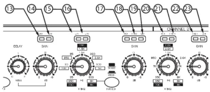
Channel Two
| 13 | LOW | Low Frequency Gain |
| 14 | LIM | Low Band Limiter |
| 15 | L/H | Crossover Low to High |
| 16 | L/M | Crossover Low to Mid |
| 17 | MID | Mid Frequency Gain |
| 18 | HMID | High-Mid Gain |
| 19 | LIM | Mid/High-Mid Band Limiter |
| 20 | M/H | Crossover Mid to High |
| 21 | HM/H | Crossover High-Mid to High |
| 22 | HIGH | High Frequency Gain |
| 23 | LIM | High Band Limiter |
flowchart
graph TD
    A["13"] --> B["14"]
    B --> C["15"]
    C --> D["16"]
    D --> E["17"]
    E --> F["18"]
    F --> G["19"]
    G --> H["20"]
    H --> I["21"]
    I --> J["22"]
    J --> K["23"]
    K --> L["CHANNEL 2"]
    M["DCLKY"] --> N["1"]
    N --> O["mHz"]
    O --> P["dB"]
    P --> Q["HFRQ"]
    Q --> R["HANCE"]
    S["GAIN"] --> T["1.0K"]
    T --> U["3.0K"]
    U --> V["3.0K"]
    V --> W["200.0K"]
    W --> X["0 dB"]
    X --> Y["HFRQ"]
    Y --> Z["HANCE"]
    AA["2.0K"] --> AB["3.0K"]
    AB --> AC["800 Hz 3.0K"]
    AC --> AD["500 Hz 800 Hz 3.0K"]
    AD --> AE["K-RHQ"]
    AE --> AF["0 dB"]
    AF --> AG["HFRQ"]
    AG --> AH["HANCE"]
Operating the S•3-Way
SETTING UP THE S•3-way FOR STEREO 3-way OPERATION
The following operating example is for a Stereo 3-way system using 15" sub, 12" mid range and 1" compression driver and both the left and right side. There are systems examples for other set-ups including stereo 2-way and 4-way mono operation.
CAUTION: Before you apply power to your speaker system amplifiers, be certain to set the frequency controls to the manufacturers recommended crossover points for the drivers or enclosures you are using.
NOTE: LAST ON / FIRST OFF
When running a loudspeaker system with one or multiple power amplifiers, it is highly recommended that you follow the LAST ON / FIRST OFF rule. When powering up your sound system, turn your power amplifier on last. When you power down your system, turn your power amplifiers off first. This will prevent any switching spikes you may get from other gear in your system, and help prevent unnecessary speaker damage.
- Connect both sets of inputs and outputs to the designated connectors on the rear panel. For a detailed cable-wiring diagram see page 15.
* Set the controls to the following positions:
| INPUT GAIN | -12 | HIGH PHASE | OUT |
| DELAY | 0 | MID PHASE | OUT |
| LOW GAIN | -6 | LOW PHASE | OUT |
| LOW/MID FREQUENCY | 70Hz | HIGH MUTE | IN |
| RANGE SWITCH | OUT | MID MUTE | IN |
| MID GAIN | -6 | LOW MUTE | IN |
| MID/HIGH FREQUENCY | 2KHz | CD EQ | OUT |
| HIGH GAIN | -6 | MONO SUB | OUT |
| MODE SWITCH | ST 3W | LIMITER | OUT |
| THRESHOLD | +5 |
- Set the controls for the S•3-way's Channel 2 to the same positions.
- Set the Power Switch to the ON position.
Operating the S·3-Way
SETTING UP THE S•3-way FOR STEREO 3-way OPERATION (Continued)
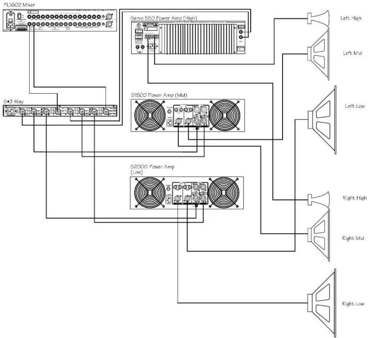
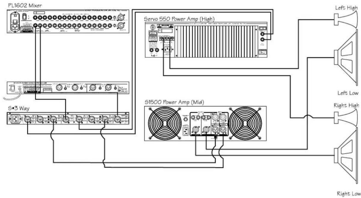
- Connect the mixer's left output to the S•3-way's CH1 (Left) input and the mixer's right output to the S•3-way's CH2 (Right) input. Now connect the S•3-way's CH1 (Left) Low Output to the left input of the low end power amp, CH1 (Left) Mid Output to the left input of mid-range power amp, and (Left) High Output to the left input of High power amp. Now make the same connections for the S•3-way's CH2(Right) and amplifiers right side.
flowchart
graph TD
    A["PL1602 Mixer"] --> B["S=3 Way"]
    A --> C["Servo 550 Power Amp (High)"]
    A --> D["S1500 Power Amp (Mid)"]
    A --> E["S2000 Power Amp (Low)"]
    C --> F["Left High"]
    C --> G["Left Mid"]
    C --> H["Left Low"]
    C --> I["Right High"]
    C --> J["Right Mid"]
    C --> K["Right Low"]
Operating the S•3-Way
SETTING UP THE S•3-way FOR STEREO 3-way OPERATION (Continued)
- Lower your power amplifier outputs to all the way off. Turn on all your power amplifiers. Run an audio signal (like some music from a CD) through your mixer and raise the output faders until you see the Input Meter LED's begin to light.
- Slowly raise the S•3-way's Input Gain until the Input Meter reads 0dB.
- Now raise your power amps to their normal operating level.
- Slowly raise the S•3-way's Ch1 (Left) Low Gain to 0 and then raise CH2 (Right) Low Gain to 0.
- Slowly raise the S•3-way's Ch1 (Left) Mid Gain to 0 and then raise CH2 (Right) MID Gain to 0.
- Slowly raise the S•3-way's Ch1 (Left) High Gain to 0 and then raise CH2 (Right) HIGH Gain 0.
- Now use your ears to adjust the balance between the low, mid and high end. You can continue to raise the Gain controls as you fine-tune the system. Watch the Peak Meters on your power amplifiers to ensure that you re running a clean signal.
S•3-way Controls
The Samson S•3-way features a variety of control functions that offer the sound engineer advanced control over a speaker system. The next section is a description of the control functions and how they are used to improve the overall sound of a sound reinforcement system.
HIGH PASS FILTER
The S•3-way incorporates a HPF (High Pass Filter) which when engaged, activates a low frequency roll off at 25 Hz. By using the HPF you eliminate the sub-sonic frequencies sent to the low frequency power amplifier. Since the amplifier will try to reproduce these frequencies with the HPF is off, in most cases the result is simply wasted energy. By using the S•3-way HPF you send just the frequency you want to reproduce to your low frequency amplifiers and speakers.
DELAY
The S•3-way features a delay that can be set for up to two milli seconds of delay time for time aligning speaker stacks.
Operating the S•3-Way
PHASE SWITCHES
The S•3-way incorporates individual PHASE reversal switches on each frequency band. When engaged, the LED illuminates indicating that the selected output is now 180 degrees out of phase.
MUTE SWITCHES
The S•3-way features Mute switches on each frequency band. When engaged, the LED illuminates and that channel output is turned off. The MUTE switches are convenient for trouble shooting or for simply listening to each speaker section separately.
CD EQ SWITCH
Many of today's popular speaker enclosures feature Constant Directivity Horns. The S•3-way's CD EQ switch can be activated to apply a special equalization curve for smoothing and adding air to the high end of a loudspeaker system.
MONO SUB SWITCH
For easy operation of mono subwoofers, the S•3-way provides a MONO SUB switch. When activated, the low frequency band of Channel One and Two are summed together. The common low frequency signal is present at both Channel One and Channel Two's Outputs.
LIMITER
A Limiter is a specific form of a compressor configured to prevent peaks and for general overload protection. The S•3-way offers a Multi-Band Limiter with variable Threshold control. The operating range of the Limiter is from -5 to +18dB and when engaged, protects against signal peaks and overloads.
S•3-Way System Set-Ups
It you're operating your PA system Stereo 2-way, wire your system as shown in the system diagram below:
flowchart
graph TD
    A["PL1602 Mixer"] --> B["S3 Way"]
    A --> C["Servo 550 Power Amp (High)"]
    A --> D["S1500 Power Amp (Mid)"]
    C --> E["Left High"]
    C --> F["Left Low"]
    C --> G["Right High"]
    C --> H["Right Low"]
    style A fill:#f9f,stroke:#333
    style B fill:#ccf,stroke:#333
    style C fill:#cfc,stroke:#333
    style D fill:#fcc,stroke:#333
    style E fill:#ffc,stroke:#333
    style F fill:#fcc,stroke:#333
    style G fill:#ffc,stroke:#333
    style H fill:#fcc,stroke:#333
Once you have your system wired-up, follow the steps below:
- Set the mode switch to the ST 2 W position. Notice how the BAND INDICATOR LED's change showing the frequencies that are now under control by the associated GAIN or FREQUENCY knobs.
• Use the first crossover on Channel 1 and 2 to set the desired frequency.
- Adjust Gain number 1 on Channel 1 and 2 for the Low frequency outputs.
- Adjust Gain number 3 on Channel 1 and 2 for the High frequency outputs.
S•3-Way System Set-Ups
It you're operating your PA system Stereo 3-way, wire your system as shown in the system diagram below.

flowchart
graph TD
    A["PL1602 Mixer"] --> B["S•3 Way"]
    A --> C["Servo 560 Power Amp (High)"]
    A --> D["S1500 Power Amp (Mid)"]
    A --> E["S2000 Power Amp (Low)"]
    C --> F["Left High"]
    C --> G["Left Mid"]
    C --> H["Left Low"]
    C --> I["Right High"]
    C --> J["Right Mid"]
    C --> K["Right Low"]
Once you have your system wired-up, follow the steps below:
- Set the mode switch to the ST 3 W position. Notice how the BAND INDICATOR LED's change showing the frequencies that are now under control by the associated GAIN or FREQUENCY knobs.
- Look for the illuminated L/M BAND INDICATOR LED over the first FREQUENCY control. Now, use the first crossover FREQ on Channel 1 to set the desired frequency dividing the Low and Mid frequencies. Now, use the second crossover FREQ on Channel 1, indicated by the illuminated M/H LED, to set the desired frequency dividing the Mid and High frequencies. Repeat the same procedure for the Channel 2.
- Look for the illuminated LOW BAND INDICATOR LED over the GAIN control. Now, adjust the first gain control on Channel 1 to set the level of the Low frequency output. Look for the MID BAND INDICATOR LED over Channel 1's second GAIN control to adjust the MID output. Adjust the High output using Channels 1's third GAIN control designated by the HIGH BAND INDICATOR LED. Repeat the same procedure for Channel 2.
S•3-Way System Set-Ups
It you're operating your PA system Mono 4-way, wire your system as shown in the system diagram below.
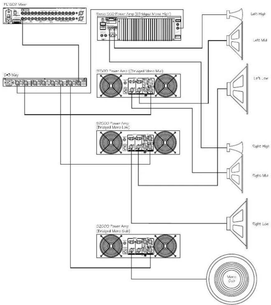
flowchart
graph TD
    A["PL 302 Mixer"] --> B["S=3 Way"]
    B --> C["S=302 Power Amp (Bridged Mono High)"]
    C --> D["Left High"]
    C --> E["Left Mid"]
    C --> F["Left Low"]
    C --> G["S=300 Power Amp (Bridged Mono Mid)"]
    G --> H["Right High"]
    G --> I["Right Mid"]
    G --> J["Right Low"]
    G --> K["S=3000 Power Amp (Bridged Mono Sub)"]
    K --> L["Mono Sub"]
Once you have your system wired-up, follow the steps below:
- Set the mode switch to the MONO 4 W position. Notice how the BAND INDICATOR LED's change showing the frequencies that are now under control by the associated GAIN or FREQUENCY knobs.
- Look for the illuminated L/LM BAND INDICATOR LED over the first FREQUENCY control. Now, use the first crossover FREQ on Channel 1 to set the desired frequency dividing the Low and Low-Mid frequencies. Now, use the second crossover FREQ on Channel 1, indicated by the illuminated LM/HM LED, to set the desired frequency dividing the Low-Mid and High-Mid frequencies. To set the frequency point dividing the High-Mid and High use Channel 2's second crossover FREQ which will have the HM/H BAND INDICATOR LED lit up.
- Look for the illuminated LOW BAND INDICATOR LED over the first GAIN control. Now, adjust the first gain control on Channel 1 to set the level of the Low frequency output. Look for the LM/HM BAND INDICATOR over Channel 1's second GAIN control to adjust the LOW-MID output. The High-Mid level is adjusted by using Channel's 2's second GAIN control indicated by the HMID LED. Adjust the High output using Channel 2's third GAIN control designated by the HIGH BAND INDICATOR LED.
S•3-Way System Set-Ups
MONO FOUR-WAY LOW
The S• 3way incorporates a special operating mode, MONO 4-WAY LOW for operating sub woofers at very low frequencies. In the MONO 4-WAY LOW mode the frequency divisions are half of those in MONO 4-WAY mode. It you're operating your PA system Mono 4-way LOW, wire your system as shown in the system diagram below:
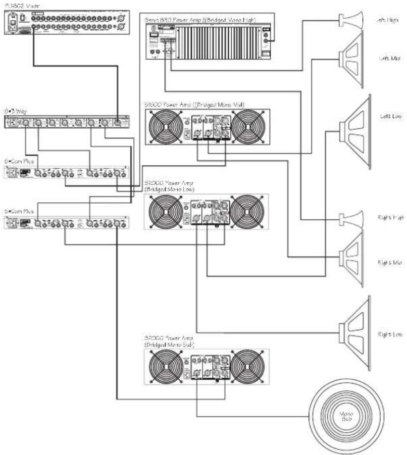
flowchart
graph TD
    A["3.16G2 Vaser"] --> B["S+3 Way"]
    A --> C["S+Com Plus"]
    A --> D["S+Com Plus"]
    B --> E["Bone B50 Power Amp (Bridged Mono High)"]
    C --> F["51600 Power Amp ((Bridged Mono Mid)"]
    D --> G["52000 Power Amp (Bridged Mono Low)"]
    E --> H["Left High"]
    E --> I["Left Mid"]
    E --> J["Left Low"]
    F --> K["Right High"]
    F --> L["Right Mid"]
    F --> M["Right Low"]
    G --> N["52000 Power Amp (Bridged Mono Sub)"]
    G --> O["52000 Power Amp (Bridged Mono Sub)"]
    N --> P["Mono Sub"]
Once you have your system wired-up, follow the steps below:
- Set the mode switch to the MONO 4 W position. Notice how the BAND INDICATOR LED's change showing the frequencies that are now under control by the associated GAIN or FREQUENCY knobs.
- Look for the illuminated L/LM BAND INDICATOR LED over the first FREQUENCY control. Now, use the first crossover FREQ on Channel 1 to set the desired frequency dividing the Low and Low-Mid frequencies. Now, use the second crossover FREQ on Channel 1, indicated by the illuminated LM/HM LED, to set the desired frequency dividing the Low-Mid and High-Mid frequencies. To set the frequency point dividing the High-Mid and High use Channel 2's second crossover FREQ which will have the HM/H BAND
- Look for the illuminated LOW BAND INDICATOR LED over the first GAIN control. Now, adjust the first gain control on Channel 1 to set the level of the Low frequency output. Look for the LM/HM BAND INDICATOR over Channel 1's second GAIN control to adjust the LOW-MID output. The High-Mid level is adjusted by using Channel's 2's second GAIN control indicated by the HMID LED. Adjust the High output using Channels 2's third GAIN control designated by the HIGH BAND INDICATOR LED.
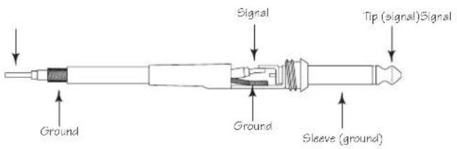
Connections
Unbalanced 1/4" Connector
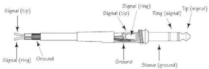
Balanced TRS 1/4" Connector
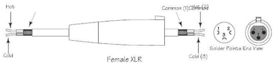
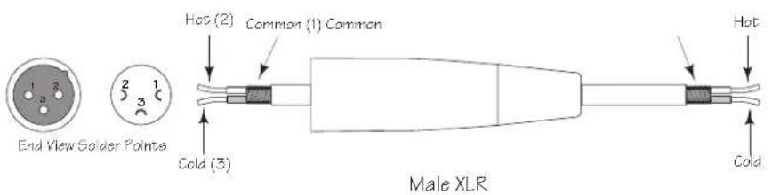
XLR Balanced Wiring Guide
SETTING UP THE S•3-way USING A REAL TIME ANALYZER
SETTING UP THE S•3-way USING A REAL TIME ANALYZER
A REAL TIME ANALYZER (RTA) is an especially useful tool for setting up your crossover, as it will enable you to set parameters like DELAY and LEVEL more accurately. Some Audio Engineers can use their ears to tune a loudspeaker system. Some will even use the crossover to create the over-all system curve using the crossover like an equalizer. For the rest of us, an accurately set crossover with a flat response is the best way to start and using a RTA is the best way to get there.
Using the RTA to Set DELAY Time.
In the real world, no single or multiple speaker system is perfect. If there were such a perfect system, it would more than likely be comprised of a single transducer that alone could faithfully reproduce the entire frequency spectrum. Because no such system exists we have to deal with the problems associated with multiple transducers. The first problem that you will encounter, whether you know it or not, is time travel. That's when the S• 3-way's delay circuit becomes especially useful.
Ideally, the sound reproduced by each driver in the loudspeaker system would be traveling through the air ultimately reaching the listeners at the same time. To accomplish this in a system using multiple drivers or enclosures, the voice coils of all the drivers would have to be lined up on the same vertical axis. This is very difficult to achieve in many cases because of the physical size of the different components, and the position of the drivers in their enclosures. It is not uncommon to have a physical distance of 2" to 24" or more between the low and high frequency drivers. For example, front loaded low frequency drivers and compression drivers mounted on a large horn. With no correction, the low frequency signal can be traveling through the air 2" to 24" in front of the high frequencies and thereby reaching the listeners at different times. Although the delay time between the low and high frequency signal may be relatively small, the negative effects can be substantial. The problem is that both drivers are reproducing frequencies at and around the crossover point, which arrive at the listeners at different times. Typically, the resulting problem is comb filtering or cancellations at the crossover frequencies.
The S•3-way features a DELAY control allowing you to dial up-to 2 milliseconds of delay. By using a RTA and the S•3-way's DELAY you can time align the drivers in your system and minimize the possibilities of comb filtering. Now follow these steps, separately, for both the left and rights sides of your loudspeaker:
- Set the crossover to the desired frequencies and press all the Mute switches to the ON position, turning all of the S •3-ways outputs off. Position your measurement microphone approximately 15 feet from your loudspeaker array, halfway between the low and high frequency drivers. Now turn all the GAIN controls to the fully counter clockwise position.
- Play a sign wave tuned to the crossover frequency, or connect a pink noise generator to your loudspeaker system either from your mixer or in the S•3-way's input. Now turn off the Low Frequency Mute switch and adjust the S• 3-way's INPUT GAIN to "0". Adjust the LOW GAIN control so that the signal is playing at a loud, but not too painful level. Make sure you only hear sound from the low frequency driver.
- Adjust the level control of the RTA until it reads OdB at the crossover frequency. Now press the LOW MUTE switch turning off the low frequency output.
SETTING UP THE S•3-way USING A REAL TIME ANALYZER
- Turn off the High Frequency MUTE switch and turn up the High Frequency Level control until the RTA reads 0dB at the crossover frequency.
- Now, press the LOW MUTE switch again turning on the low frequency output. Notice the reading on the RTA at the crossover frequency. If the reading is 0dB, there is no need to adjust the delay time and you can assume that the speakers are in phase. If the RTA reads less than +3dB you'll need to delay the low frequency.
- While watching the RTA display, slowly turn the DELAY control counter-clockwise until the display reads +3dB.
Setting the GAIN Controls Using a RTA
It is critical to set the GAIN output controls so that all the frequency bands combine to create an over-all flat system response. Using a RTA to set the GAIN control will make it much easier for you to accomplish a flat system response. Follow the steps below, separately for each side of your system, to set the GAIN controls using a RTA.
- With the crossover set to the desired frequencies, press all the Mute switches to the ON position, turning all of the S•3-way's outputs off. Position your measurement microphone approximately 15 feet from your loudspeaker array at a level ranging from your chest to your ear. Now turn all the GAIN controls to the fully counter clockwise position.
- Play a sign wave tuned to the crossover frequency, or connect the signal from a pink noise generator to your loudspeaker system, either from your mixer or directly in the S•3-way's input. Now turn off the Low Frequency Mute switch and adjust the S•3-way's INPUT GAIN to "0".
- Adjust the LOW GAIN control until the RTA has an average reading of OdB at and below the frequency of the LOW crossover point.
- Turn off the Mid Frequency Mute switch and turn up the MID Frequency GAIN control until the RTA reads the same average level in the MID band.
- Adjust the HIGH GAIN control until the RTA has an average reading of OdB at and above the frequency of the HIGH crossover point.
At this point all of the frequency bands will be at the same level and your system will have a flat response. After setting the levels you can use a graphic equalizer, like the Samson E62I, if you want set a particular response curve to tune the speaker system for a specific sound.
flowchart
graph TD
    A["PL1602 Mixer"] --> B["S=3 Way"]
    A --> C["Servo 550 Power Amp (High)"]
    A --> D["S1500 Power Amp (Mid)"]
    A --> E["S2000 Power Amp (Low)"]
    C --> F["Left High"]
    C --> G["Left Mid"]
    C --> H["Left Low"]
    C --> I["Right High"]
    C --> J["Right Mid"]
    C --> K["Right Low"]
TOUCHES MUTE
flowchart
graph TD
    A["PL1602 Mixer"] --> B["S-3 Way"]
    A --> C["Servo 560 Power Amp (High)"]
    A --> D["S1500 Power Amp (Mid)"]
    A --> E["S2000 Power Amp (Low)"]
    C --> F["Left High"]
    C --> G["Left Mid"]
    C --> H["Left Low"]
    C --> I["Right High"]
    C --> J["Right Mid"]
    C --> K["Right Low"]
flowchart
graph TD
    A["PL 302 Mixer"] --> B["S-3 Way"]
    A --> C["Servo 550 Power Amp (Bridged Mono High)"]
    A --> D["S1500 Power Amp ((Bridged Mono Mid)"]
    A --> E["S2000 Power Amp (Bridged Mono Low)"]
    A --> F["S2000 Power Amp (Bridged Mono Sub)"]
    C --> G["Left High"]
    C --> H["Left Mid"]
    C --> I["Left Low"]
    D --> J["Right High"]
    D --> K["Right Mid"]
    D --> L["Right Low"]
    F --> M["Mono Sub"]
flowchart
graph TD
    A["S1802 Vaser"] --> B["Bense B50 Power Amp (Bridged Mono High)"]
    A --> C["Si600 Power Amp ((Bridged Mono Mid)"]
    A --> D["B2000 Power Amp (Bridged Mono Low)"]
    A --> E["B2000 Power Amp (Bridged Mono Sub)"]
    B --> F["Left High"]
    B --> G["Left Mid"]
    B --> H["Left Low"]
    C --> I["Right High"]
    C --> J["Right Mid"]
    C --> K["Right Low"]
    D --> L["Mono Sub"]
    E --> M["Mono Sub"]
| 1 | LOW | Low Frequency Gain |
| 2 | LIM | Low Band Limiter |
| 3 | L/H | Crossover Low/High |
| 4 | L/M | Crossover Low/Mid |
| 5 | L/LM | Crossover Low/Low-Mid |
| 6 | MID | Mid Frequency Gain |
| 7 | LMID | Low-Mid Gain |
| 8 | LIM | Mid/Low-Mid Band Limiter |
| 9 | M/H | Crossover Mid/High |
| 10 | LM/HM | Crossover Low-Mid/High-Mid |
| 11 | HIGH | High Frequency Gain |
| 12 | LIM | High Band Limiter |
Kanal Zwei
| 13 | LOW | Low Frequency Gain |
| 14 | LIM | Low Band Limiter |
| 15 | L/H | Crossover Low/High |
| 16 | L/M | Crossover Low/Mid |
| 17 | MID | Mid Frequency Gain |
| 18 | HMID | High-Mid Gain |
| 19 | LIM | Mid/High-Mid Band Limiter |
| 20 | M/H | Crossover Mid/High |
| 21 | HM/H | Crossover High-Mid/High |
| 22 | HIGH | High Frequency Gain |
| 23 | LIM | High Band Limiter |
flowchart
graph TD
    A["1"] --> B["2"]
    B --> C["3"]
    C --> D["4"]
    D --> E["5"]
    E --> F["7"]
    F --> G["8"]
    G --> H["9"]
    H --> I["10"]
    I --> J["CHANNEL"]
    J --> K["11"]
    K --> L["12"]
    L --> M["13"]
    M --> N["14"]
    N --> O["15"]
    O --> P["16"]
    P --> Q["17"]
    Q --> R["18"]
    R --> S["19"]
    S --> T["20"]
    T --> U["21"]
    U --> V["22"]
    V --> W["23"]
    W --> X["24"]
    X --> Y["25"]
    Y --> Z["26"]
    Z --> AA["27"]
    AA --> AB["28"]
    AB --> AC["29"]
    AC --> AD["30"]
    AD --> AE["31"]
    AE --> AF["32"]
    AF --> AG["33"]
    AG --> AH["34"]
    AH --> AI["35"]
    AI --> AJ["36"]
    AJ --> AK["37"]
    AK --> AL["38"]
    AL --> AM["39"]
    AM --> AN["40"]
    AN --> AO["41"]
    AO --> AP["42"]
    AP --> AQ["43"]
    AQ --> AR["44"]
    AR --> AS["45"]
    AS --> AT["46"]
    AT --> AU["47"]
    AU --> AV["48"]
    AV --> AW["49"]
    AW --> AX["50"]
S•3-Way bedienen
flowchart
graph TD
    A["PL1602 Mixer"] --> B["S•3 Way"]
    A --> C["Servo 550 Power Amp (High)"]
    A --> D["S1500 Power Amp (Mid)"]
    A --> E["S2000 Power Amp (Low)"]
    C --> F["Left High"]
    C --> G["Left Mid"]
    C --> H["Left Low"]
    C --> I["Right High"]
    C --> J["Right Mid"]
    C --> K["Right Low"]
MUTE-TASTEN
CD EQ-TASTE
LIMITER
flowchart
graph TD
    A["PL1802 Mixer"] --> B["Sava 550 Power Amp (High)"]
    A --> C["S1500 Power Amp (Mid)"]
    A --> D["S2000 Power Amp (Low)"]
    B --> E["Left High"]
    B --> F["Left Mid"]
    C --> G["Left Low"]
    C --> H["Right High"]
    C --> I["Right Mid"]
    D --> J["Right Low"]
flowchart
graph TD
    A["PL1602 Mixer"] --> B["S43 Way"]
    A --> C["S1500 Power Amp (Bridged Mono Mix)"]
    A --> D["S2000 Power Amp (Bridged Mono Mix)"]
    A --> E["S2000 Power Amp (Bridged Mono Sub)"]
    C --> F["Left High"]
    C --> G["Left Mid"]
    C --> H["Left Low"]
    D --> I["Right High"]
    D --> J["Right Mid"]
    D --> K["Right Low"]
    E --> L["Mono Sub"]
flowchart
graph TD
    A["PL1602 Mixer"] --> B["Servo 550 Power Amp (High)"]
    A --> C["S1500 Power Amp (Mid)"]
    A --> D["S2000 Power Amp (Low)"]
    B --> E["Left High"]
    B --> F["Left Mid"]
    C --> G["Left Low"]
    C --> H["Right High"]
    C --> I["Right Mid"]
    D --> J["Right Low"]
CONFIGURAR EL S•3-way PARA EL MODO ESTÉREO DE 3 VÍAS (Cont.)
CONMUTADORES MUTE
LIMITER
flowchart
graph TD
    A["PL1602 Mixer"] --> B["S-3 Way"]
    A --> C["Servo 560 Power Amp (High)"]
    A --> D["S1500 Power Amp (Mid)"]
    A --> E["S2000 Power Amp (Low)"]
    C --> F["Left High"]
    C --> G["Left Mid"]
    C --> H["Left Low"]
    C --> I["Right High"]
    C --> J["Right Mid"]
    C --> K["Right Low"]
flowchart
graph TD
    A["PL 3002 Mixer"] --> B["S-3 Way"]
    B --> C["Servo 550 Power Amp (Bridged Mono High)"]
    C --> D["Left High"]
    C --> E["Left Mid"]
    C --> F["Left Low"]
    C --> G["S-600 Power Amp ((Bridged Mono Mid)"]
    G --> H["S-6000 Power Amp (Bridged Mono Low)"]
    H --> I["S-6000 Power Amp (Bridged Mono Sub)"]
    I --> J["Right High"]
    I --> K["Right Mid"]
    I --> L["Right Low"]
    I --> M["Mono Sub"]
Impedance Balanced >15k Ohms
Max. Input level +26dBu balanced
Outputs
Male Balanced XLR
Impedance Balanced 100 Ohms
Max. Output Level +26 dBu
Global Specifications
Frequency Response <10 Hz to >90 kHz, +0/-3 dB
Signal to Noise
(Ref +4 dBu), 22 Hz to 22 kHz, un-weighted 90dB high out, mid 90dB, low 94dB, all outs >100dB muted.
CMRR Min.40dB, >55 dB @ 1 kHz
Crossover
Crossdover Type Linkwitz-Riley, 24 dB/Octave
Crossover 1 Channel 1 35 to 800Hz
350 to 8kHz / with 10X multiplier
18 to 400Hz /4 Way Low Mode
Crossover 1 Channel 2 35 to 800Hz
350 to 8kHz / with 10X multiplier
Crossover 2 Channel 1 350 to 8kHz
175 to 4kHz /4 Way Low Mode
Crossover 2 Channel 2 350 to 8kHz
700 to 8kHz /4 Way Low Mode
Function Switches
Front Panel
High Pass Filter -3dB @ 15Hz 3 pole, 18dB/Octave
Mute for individual outputs
Phase Inverts the phase of the individual output
CD EQ Corrects constant directivity horn frequencies above 3.5 kHz
Limiter
engages limiter for all outputs
Mono Sub
Sends the low frequency signal from both inputs to both low outputs
Power Supply
Mains Voltages USA/Canada
105-125 VAC \~, 60 Hz
Mains Voltages Europe
215-254 VAC\~,50Hz
Power Consumption
14 Watts
Power Inlet
Standard IEC receptacle / with Fuse
Physical
Dimensions
1 3/4" (44,5 mm) * 19" (482,6 mm) * 8 1/2" (217 mm)
Net Weight
6.6lbs., (3 kg)
Shipping Weight
9.4lbs., (4,3 kg)
Block Diagram
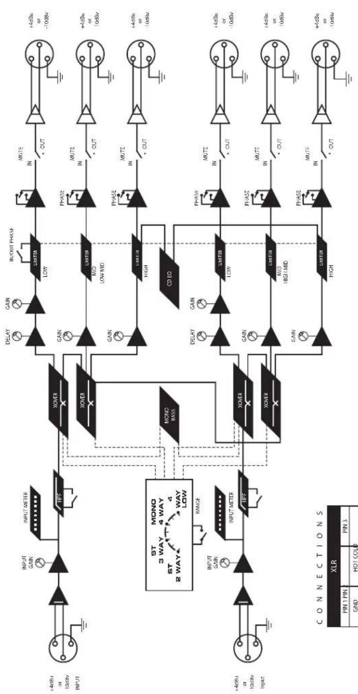
flowchart
graph TD
    A["Input"] --> B["INPUT GAIN"]
    B --> C["INPUT METER"]
    C --> D["XOVER"]
    D --> E["DELAY"]
    D --> F["GAIN"]
    D --> G["IN/OUT PHASE"]
    G --> H["MUTE IN"]
    H --> I["+4dBu or -10dBv"]
    D --> J["GAIN"]
    J --> K["LIMTER LOW"]
    K --> L["PHASE IN"]
    L --> M["+4dBu or 10dBv"]
    D --> N["GAIN"]
    N --> O["LIMTER MID LOW MID"]
    O --> P["PHASE IN"]
    P --> Q["+4dBu or -10dBv"]
    D --> R["GAIN"]
    R --> S["LIMTER HIGH"]
    S --> T["PHASE IN"]
    T --> U["+4dBu or -10dBv"]
    D --> V["MONO BASES"]
    V --> W["CD ED"]
    W --> X["DELAY"]
    W --> Y["GAIN"]
    W --> Z["LIMTER LOW"]
    Z --> AA["PHASE IN"]
    AA --> AB["+4dBu or -10dBv"]
    V --> AC["MONO 3 WAY"]
    AC --> AD["ST 2 WAY"]
    AD --> AE["RANGE"]
    AE --> AF["INPUT METER"]
    AF --> AG["XOVER"]
    AG --> AH["GAIN"]
    AG --> AI["LIMTER MID HIGH MID"]
    AI --> AJ["PHASE IN"]
    AJ --> AK["+4dBu or 10dBv"]
    AG --> AL["GAIN"]
    AL --> AM["LIMTER HIGH"]
    AM --> AN["PHASE IN"]
    AN --> AO["+4dBu or -10dBv"]
www.samsontech.com
CE
| Modes | Operating Frequencies Ch 1 A | Operating Frequencies Ch 1B | Operating Frequencies Ch 2 A | Operating Frequencies Ch 2B |
| Stereo 2 Way | 35Hz to 800Hz X1 or 350Hz to 8KHz | 350Hz to 8KHz | 35Hz to 800Hz X1 or 350Hz to 8KHz | 350Hz to 8KHz |
| Stereo 3 Way | 35Hz to 800Hz X1 or 350Hz to 8KHz | 350Hz to 8KHz | 35Hz to 800Hz X1 or 350Hz to 8KHz | 350Hz to 8KHz |
| Mono 4 Way | 35Hz to 800Hz | 350Hz to 8KHz | 350Hz to 8KHz | |
| Mono 4 Way Low | 18Hz to 400Hz | 175Hz to 4KHz | 700Hz to 8KHz |
3 WAY STEREO / 4 WAY MONO XOVER
Designed and Engineered in the United States by Samson Technologies
Samson Technologies Corp.
575 Underhill Blvd.
P.O. Box 9031
Syosset, NY 11791-9031
Phone: 1-800-3-SAMSON (1-800-372-6766)
Fax: 516-364-3888
www.samsontech.com
- Owners Manual
- Safety Instructions
- CAUTION
- ATTENTION
- WARNING
- AVIS
- Important Safety Instructions
- Table of Contents
- Introduction
- S•3-Way Features
- Controls and Functions
- FRONT PANEL LAYOUT
- REAR PANEL LAYOUT
- Operating the S•3-way
- SETTING UP THE S•3-way
- MODE SWITCH
- FREQUENCY BAND & LIMIT INDICATORS
- SETTING UP THE S•3-way FOR STEREO 3-way OPERATION
- NOTE: LAST ON / FIRST OFF
- Operating the S·3-Way
- SETTING UP THE S•3-way FOR STEREO 3-way OPERATION (Continued)
- S•3-way Controls
- HIGH PASS FILTER
- DELAY
- PHASE SWITCHES
- MUTE SWITCHES
- CD EQ SWITCH
- MONO SUB SWITCH
- LIMITER
- S•3-Way System Set-Ups
- MONO FOUR-WAY LOW
- Connections
- SETTING UP THE S•3-way USING A REAL TIME ANALYZER
- Using the RTA to Set DELAY Time.
- Setting the GAIN Controls Using a RTA
- TOUCHES MUTE
- S•3-Way bedienen
- MUTE-TASTEN
- CD EQ-TASTE
- CONFIGURAR EL S•3-way PARA EL MODO ESTÉREO DE 3 VÍAS (Cont.)
- CONMUTADORES MUTE
- Block Diagram
Brand : SAMSON
Model : S.3way
Category : Hi-fi system