PA4000RC - Mixer Monacor - Free user manual and instructions
Find the device manual for free PA4000RC Monacor in PDF.
| Product type | 4-zone Public Address Amplifier-Mixer |
| Brand | Monacor |
| Model | PA4000RC (PA-40120 amplifier) |
| RMS output power | 4 × 120 W |
| Peak output power | 4 × 170 W |
| Frequency response | 45 – 20,000 Hz (-3 dB) |
| Signal-to-noise ratio (LINE input) | > 90 dB (A-weighted) |
| Signal-to-noise ratio (MIC input) | > 70 dB (A-weighted) |
| Distortion factor | < 1% (1 kHz) |
| Mic/line inputs (CH1-CH3) | 3 × combo XLR/6.35 mm jack, balanced, adjustable sensitivity (MIC/LINE), switchable 15 V phantom power |
| Line inputs (CH4-CH5) | 2 × RCA, unbalanced, 245 mV / 15 kΩ |
| PAGING input | Screw terminals, line level, 245 mV / 10 kΩ, balanced, high priority |
| Speaker outputs (Z1-Z4) | 4 zones, 100 V / 70 V / 4 Ω, max. 120 W per zone |
| PRE OUT outputs | 4 × screw terminals, balanced line level, 775 mV / 200 Ω |
| REC and MONITOR outputs | RCA (REC) and 6.35 mm jack (MONITOR), 775 mV / 3 kΩ (REC) / 200 Ω (MONITOR) |
| EMER. OUT output | 4 × screw terminals, 24 V DC / 200 mA for forced announcement relay |
| FAULT relay | Floating switching contact, 24 V / 500 mA max. |
| Equalizer | BASS ±10 dB / 100 Hz, TREBLE ±10 dB / 10 kHz (per channel CH1-CH5) |
| Built-in gong | 2-tone, 4-tone, or siren (internally selectable) |
| Mains power supply | 230 V / 50 Hz, max. power consumption 1500 VA |
| Emergency power supply | 24 V DC, max. current consumption 40 A |
| Dimensions (W × H × D) | 482 × 90 × 377 mm (2 U) |
| Weight | 22.1 kg |
| Operating temperature | 0 – 40 °C |
| Maintenance and cleaning | Dry, soft cloth; no chemicals or water |
| Safety | Overload and overheat protection; power-on delay; mandatory grounding |
| Spare parts and repairability | Replacement fuse of same type; repair only by authorized technician |
| General information | Designed for Public Address installations; 19" rack mountable; up to 32 PA-4000RC remote microphones connectable |
Frequently Asked Questions - PA4000RC Monacor
User questions about PA4000RC Monacor
0 question about this device. Answer the ones you know or ask your own.
Ask a new question about this device
Download the instructions for your Mixer in PDF format for free! Find your manual PA4000RC - Monacor and take your electronic device back in hand. On this page are published all the documents necessary for the use of your device. PA4000RC by Monacor.
USER MANUAL PA4000RC Monacor
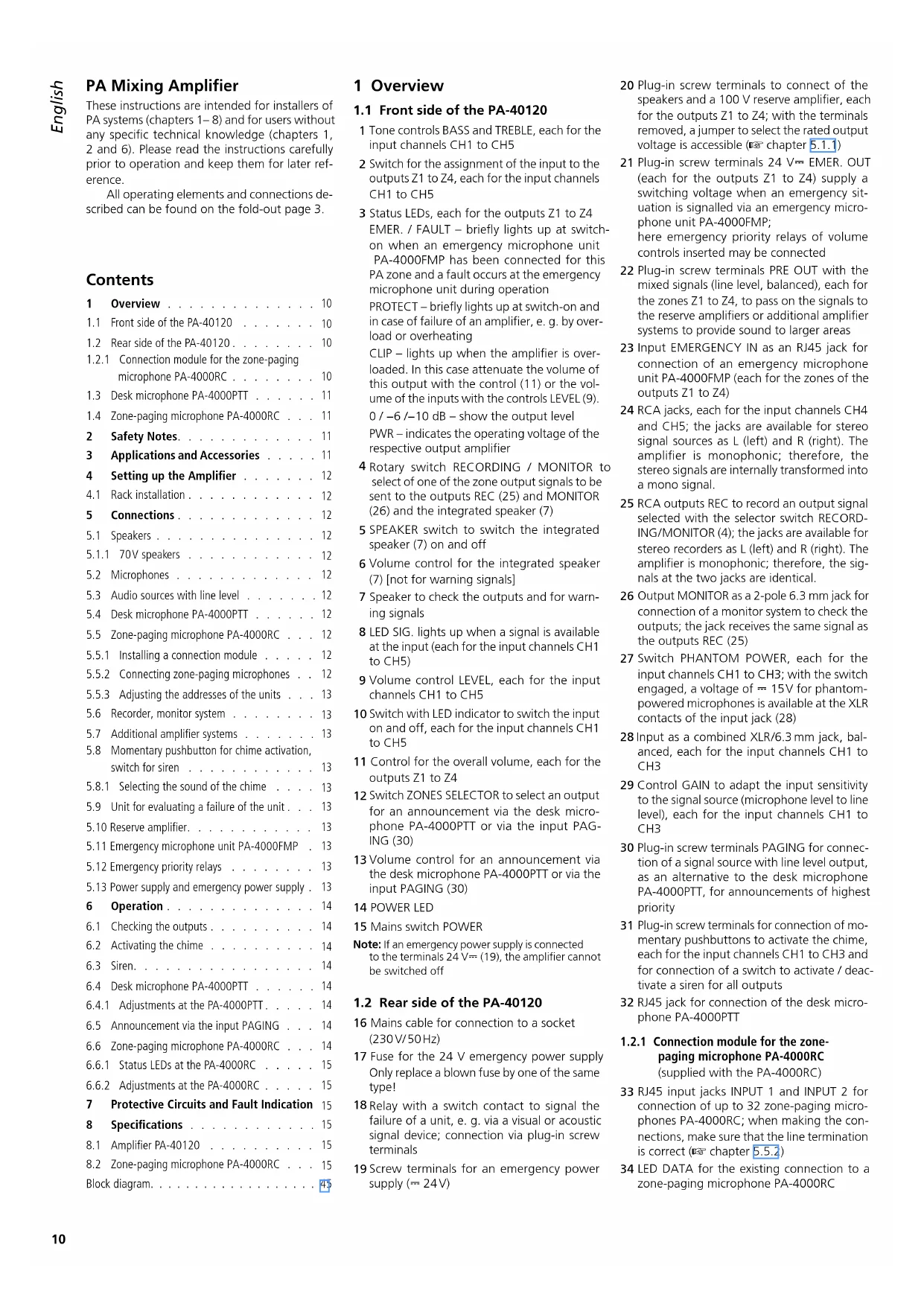
natural_image
Two desktop computer devices with black speakers and indicator lights, no visible text or symbols on the devices themselves.CE
BEDIENUNGSANLEITUNG
INSTRUCTION MANUAL
MODE D'EMPLOI
ISTRUZIONI PER L'USO
text_image
④ PA-4000PTT 35 MONACOR TA-4000PTT 36 37 TALK PTS/CHIME PTT REMOTE 38 39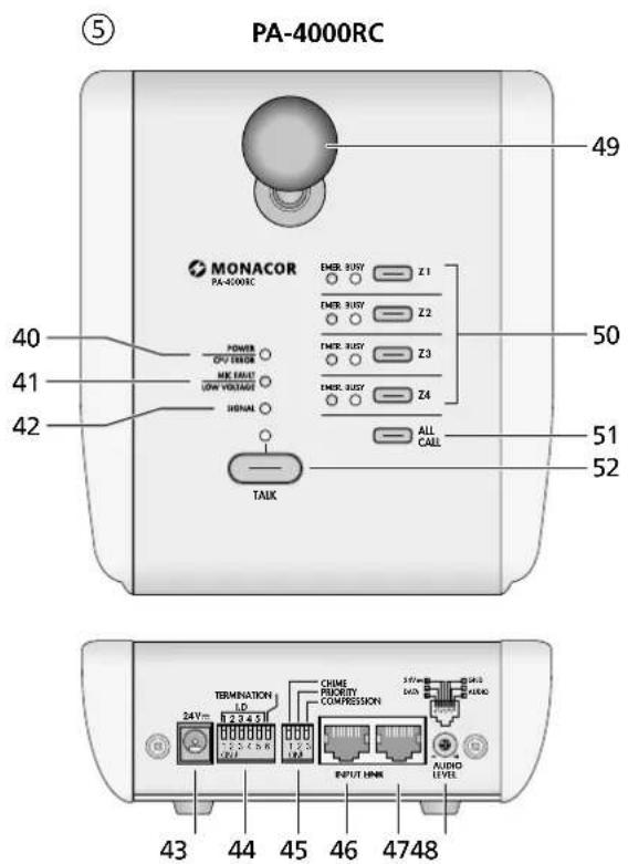
text_image
⑤ PA-4000RC MONACOR PA-4000RC POWER DVO ERROR ME MAX USB VOLTAGE SHENAN TALK EMER. RUST Z1 EMER. RUST Z2 EMER. RUST Z3 EMER. RUST Z4 ALL CALL 50 51 52 49 40 41 42 43 44 45 46 47 48 TERMINATION LD 24V 2.2 4.5 V 1.2 V CHIME PRIORITY COMPRESSION 3.6V 3.6V AUDIO LEVELELA-Mischverstärker
These instructions are intended for installers of PA systems (chapters 1–8) and for users without any specific technical knowledge (chapters 1, 2 and 6). Please read the instructions carefully prior to operation and keep them for later reference.
All operating elements and connections described can be found on the fold-out page 3.
Contents
1 Overview 10
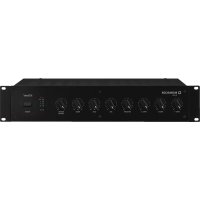
1.1 Front side of the PA-40120 ..... 10
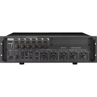
1.2 Rear side of the PA-40120 ..... 10
1.2.1 Connection module for the zone-paging microphone PA-4000RC ..... 10
1.3 Desk microphone PA-4000PTT ..... 11
1.4 Zone-paging microphone PA-4000RC . . . 11
2 Safety Notes. 11
3 Applications and Accessories ..... 11
4 Setting up the Amplifier 12
4.1 Rack installation ..... 12
5 Connections 12
5.1 Speakers ..... 12
5.1.1 70V speakers ..... 12
5.2 Microphones 12
5.3 Audio sources with line level ..... 12
5.4 Desk microphone PA-4000PTT ..... 12
5.5 Zone-paging microphone PA-4000RC . . . 12
5.5.1 Installing a connection module ..... 12
5.5.2 Connecting zone-paging microphones . . 12
5.5.3 Adjusting the addresses of the units . . . 13
5.6 Recorder, monitor system 13
5.7 Additional amplifier systems ..... 13
5.8 Momentary pushbutton for chime activation, switch for siren 13
5.8.1 Selecting the sound of the chime ..... 13
5.9 Unit for evaluating a failure of the unit . . . 13
5.10 Reserve amplifier.... 13
5.11 Emergency microphone unit PA-4000FMP . 13
5.12 Emergency priority relays ..... 13
5.13 Power supply and emergency power supply . 13
6 Operation....14
6.1 Checking the outputs ..... 14
6.2 Activating the chime ..... 14
6.3 Siren. 14
6.4 Desk microphone PA-4000PTT ..... 14
6.4.1 Adjustments at the PA-4000PTT ..... 14
6.5 Announcement via the input PAGING . . . 14
6.6 Zone-paging microphone PA-4000RC . . . 14
6.6.1 Status LEDs at the PA-4000RC ..... 15
6.6.2 Adjustments at the PA-4000RC ..... 15
7 Protective Circuits and Fault Indication 15
8 Specifications 15
8.1 Amplifier PA-40120 15
8.2 Zone-paging microphone PA-4000RC . . . 15
Block diagram. 45
1 Overview
1.1 Front side of the PA-40120
1 Tone controls BASS and TREBLE, each for the input channels CH1 to CH5
2 Switch for the assignment of the input to the outputs Z1 to Z4, each for the input channels CH1 to CH5
3 Status LEDs, each for the outputs Z1 to Z4 EMER. / FAULT – briefly lights up at switch-on when an emergency microphone unit PA-4000FMP has been connected for this PA zone and a fault occurs at the emergency microphone unit during operation
PROTECT – briefly lights up at switch-on and in case of failure of an amplifier, e. g. by overload or overheating
CLIP – lights up when the amplifier is overloaded. In this case attenuate the volume of this output with the control (11) or the volume of the inputs with the controls LEVEL (9).
0 / -6 / -10 dB – show the output level PWR – indicates the operating voltage of the respective output amplifier
4 Rotary switch RECORDING / MONITOR to select of one of the zone output signals to be sent to the outputs REC (25) and MONITOR (26) and the integrated speaker (7)
5 SPEAKER switch to switch the integrated speaker (7) on and off
6 Volume control for the integrated speaker (7) [not for warning signals]
7 Speaker to check the outputs and for warning signals
8 LED SIG. lights up when a signal is available at the input (each for the input channels CH1 to CH5)
9 Volume control LEVEL, each for the input channels CH1 to CH5
10 Switch with LED indicator to switch the input on and off, each for the input channels CH1 to CH5
11 Control for the overall volume, each for the outputs Z1 to Z4
12 Switch ZONES SELECTOR to select an output for an announcement via the desk microphone PA-4000PTT or via the input PAGING (30)
13 Volume control for an announcement via the desk microphone PA-4000PTT or via the input PAGING (30)
14 POWER LED
15 Mains switch POWER
Note: If an emergency power supply is connected to the terminals 24 V= (19), the amplifier cannot be switched off
1.2 Rear side of the PA-40120
16 Mains cable for connection to a socket (230V/50Hz)
17 Fuse for the 24 V emergency power supply Only replace a blown fuse by one of the same type!
18 Relay with a switch contact to signal the failure of a unit, e. g. via a visual or acoustic signal device; connection via plug-in screw terminals
19 Screw terminals for an emergency power supply ( 24V)
20 Plug-in screw terminals to connect of the speakers and a 100 V reserve amplifier, each for the outputs Z1 to Z4; with the terminals removed, a jumper to select the rated output voltage is accessible ( chapter 5.1.1)
21 Plug-in screw terminals 24 V=EMER. OUT (each for the outputs Z1 to Z4) supply a switching voltage when an emergency situation is signalled via an emergency microphone unit PA-4000FMP; here emergency priority relays of volume controls inserted may be connected
22 Plug-in screw terminals PRE OUT with the mixed signals (line level, balanced), each for the zones Z1 to Z4, to pass on the signals to the reserve amplifiers or additional amplifier systems to provide sound to larger areas
23 Input EMERGENCY IN as an RJ45 jack for connection of an emergency microphone unit PA-4000FMP (each for the zones of the outputs Z1 to Z4)
24 RCA jacks, each for the input channels CH4 and CH5; the jacks are available for stereo signal sources as L (left) and R (right). The amplifier is monophonic; therefore, the stereo signals are internally transformed into a mono signal.
25 RCA outputs REC to record an output signal selected with the selector switch RECORDING/MONITOR (4); the jacks are available for stereo recorders as L (left) and R (right). The amplifier is monophonic; therefore, the signals at the two jacks are identical.
26 Output MONITOR as a 2-pole 6.3 mm jack for connection of a monitor system to check the outputs; the jack receives the same signal as the outputs REC (25)
27 Switch PHANTOM POWER, each for the input channels CH1 to CH3; with the switch engaged, a voltage of = 15V for phantom-powered microphones is available at the XLR contacts of the input jack (28)
28 Input as a combined XLR/6.3 mm jack, balanced, each for the input channels CH1 to CH3
29 Control GAIN to adapt the input sensitivity to the signal source (microphone level to line level), each for the input channels CH1 to CH3
30 Plug-in screw terminals PAGING for connection of a signal source with line level output, as an alternative to the desk microphone PA-4000PTT, for announcements of highest priority
31 Plug-in screw terminals for connection of momentary pushbuttons to activate the chime, each for the input channels CH1 to CH3 and for connection of a switch to activate / deactivate a siren for all outputs
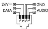
32 RJ45 jack for connection of the desk microphone PA-4000PTT
1.2.1 Connection module for the zone-paging microphone PA-4000RC (supplied with the PA-4000RC)
33 RJ45 input jacks INPUT 1 and INPUT 2 for connection of up to 32 zone-paging microphones PA-4000RC; when making the connections, make sure that the line termination is correct ( chapter 5.5.2)
34 LED DATA for the existing connection to a zone-paging microphone PA-4000RC
1.3 Desk microphone PA-4000PTT
(accessory available separately)
35 Microphone cartridge with windscreen
36 LED indicator, lights up with the talk button (37) pressed
37 TALK button; for an announcement, keep the button pressed and wait for the chime, if necessary
38 Switch for priority circuit and preliminary chime
PRIORITY – for use at the PA-40120, leave this switch in the upper position as the priority of this microphone is defined in the amplifier (for a better intelligibility of an announcement, the other input signals are muted as soon as talking starts or the chime sounds) CHIME – in position ON, first a chime sounds when the TALK button (37) is pressed
39 Jack for connection to the amplifier
1.4 Zone-paging microphone PA-4000RC
(accessory available separately)
40 LED POWER / CPU ERROR lights up as soon as the supply voltage is available; flashes in case of a malfunction of the microprocessor in the PA-4000RC
41 LED MIC FAULT/ LOW VOLTAGE lights up in case of failure of the microphone, flashes if the supply voltage is too low
42 LED SIGNAL lights up when a microphone signal is available
43 Jack 24V= for additional voltage supply via a power supply unit with a low-voltage plug 5.5/2.1mm(outside/inside diameter) and any polarity; the additional power supply unit is required if the supply via the amplifier is not sufficient (e.g. when more than 10 PA-4000RC units are connected or a cable with a length >500 m is used)
44 Switch for the address and the line termination
I.D - with these 5 switches, different addresses have to be adjusted at all PA-4000RC units prior to connection to the amplifier ( chapter 5.5.3)
TERMINATION – at the final PA-4000RC connected in a chain, set the switch to ON in order to activate the terminating resistor
45 Switch
CHIME – in position ON, first a chime sounds when pressing the TALK button (52)
PRIORITY – in position ON, the PA-4000RC takes priority over all other microphones without this function activated, and it is able to interrupt their announcements
COMPRESSION – in position ON, the dynamic power of the microphone signal is attenuated to reduce distortions when talking at high volume
46 RJ45 jack INPUT for connection of another PA-4000RC
47 RJ45 jack LINK for connection to a jack INPUT (33) of the connection module at the amplifier or the jack INPUT (46) of another PA-4000RC
48 Control AUDIO LEVEL to adjust the volume of the announcement
49 Microphone cartridge with windscreen
50 Buttons for selection of the announcement zones, each with the following status LEDs: BUSY – lights up when the zone for an announcement has been selected; if an announcement is being made via a different PA-4000RC, the LEDs for the respective zones starts flashing
EMER. – lights up when an emergency situation has been signalled in the zone (via an emergency microphone unit PA-4000FMP)
51 Button ALL CALL to simultaneously select and deselect all zones for an announcement
52 TALK button; for an announcement keep the button pressed and wait for the chime, if necessary
The LED indicator above it lights up as long as the button is pressed; the other input signals of the amplifier (e.g. music) are muted for a better intelligibility of the announcement
2 Safety Notes
The unit corresponds to all relevant directives of the EU and is therefore marked with C€
WARNING
The unit is supplied with hazardous mains voltage. Leave servicing to skilled personnel only. Do not insert anything through
the air vents. Inexpert handling of the unit may cause an electric shock hazard.
- The unit is suitable for indoor use only. Protect it against dripping water and splash water, high air humidity, and heat (admissible ambient temperature range 0–40°C).
- Do not place any vessels filled with liquid, e. g. drinking glasses, on the unit.
- The heat being generated in the unit must be carried off by air circulation. Therefore, the air vents at the housing must not be covered.
- Do not set the unit into operation, and immediately disconnect the mains plug from the mains socket if
- there is visible damage to the unit or to the mains cable,
- a defect might have occurred after a drop or similar accident,
- malfunctions occur.
The unit must in any case be repaired by skilled personnel.
- Never pull the mains cable to disconnect the mains plug from the mains socket, always seize the plug.
- A damaged mains cable must only be replaced by skilled personnel.
- For cleaning only use a dry, soft cloth, never use chemicals or water.
- No guarantee claims for the unit and no liability for any resulting personal damage or material damage will be accepted if the unit is used for other purposes than originally intended, if it is not correctly connected or operated, or if it is not repaired in an expert way.
- Important for UK Customers!
The wires in this mains lead are coloured in accordance with the following code:
green/yellow=earth
blue = neutral
brown = live
As the colours of the wires in the mains lead of this appliance may not correspond with the coloured markings identifying the terminals in your plug, proceed as follows:
- The wire which is coloured green and yellow must be connected to the terminal in the plug which is marked with the letter E or by the earth symbol 12 , or coloured green or green and yellow.
- The wire which is coloured blue must be connected to the terminal which is marked with the letter N or coloured black.
- The wire which is coloured brown must be connected to the terminal which is marked with the letter L or coloured red.
Warning – This appliance must be earthed.

If the unit is to be put out of operation definitively, take it to a local recycling plant for a disposal which is not harmful to the environment.
3 Applications and Accessories
This amplifier with 4 independent outputs and an RMS output power of 120 W each is especially designed for PA applications. Either PA speakers (100 V or 70 V) or low-impedance speakers (minimum impedance 4 Ω) can be used at the output. Further equipment:
- 3 input channels with adjustable sensitivity from line level to microphone level, with XLR / 6.3 mm connectors; phantom power (15 V) for each channel to be switched on individually
- 2 input channels for signals with line level via RCA connectors
- 1 input channel for announcement signals with line level via screw terminals (PAGING)
- 1 desk microphone PA-4000PTT with talk button, to be connected (accessory)
- 32 zone-paging microphones PA-4000RC with zone selection and status LEDs, to be connected (accessory)
- input signals can be assigned to the 4 outputs as desired
- 4 emergency microphones PA-4000FMP with microphone and announcement recorder, to be connected (accessory)
- Switching voltage for each of the 4 zones to control emergency priority relays in case of emergency
- 1 monitor output to check the outputs and for recording purposes
- 1 internal monitor speaker
– signal chime, to be activated via additional momentary pushbuttons, e. g. to precede an announcement; the type of chime (2-tone, 4-tone, siren) can be selected internally
– siren sound for alarm via additional switch - 4 reserve amplifiers to be connected; in case of failure of an output, the unit is automatically switched to the corresponding reserve amplifier (only if 100 / 70V speakers are used)
– input for a 24 V emergency power supply unit for operation in case of mains failure
Important announcements will become more intelligible when the inputs take different priorities. Then the signals of an input of lower priority
are automatically muted when an announcement is made via an input of higher priority. The priority structure is as follows:
| Priority Input | |
| 1 (high) PA-4000FMP, PA-4000PTT, PAGING | |
| 2 PA-4000RC (PRIORITY = ON) | |
| 3 PA-4000RC (PRIORITY = OFF) | |
| 4 CH1, CH2, CH3 | |
| 5 (low) CH4, CH5 | |
⑥ Input priorities
4 Setting up the Amplifier
The amplifier is provided for rack installation for units with a width of 482 mm (19") but it can also be used as a tabletop unit. Air must always be allowed to move freely through all vents so that a sufficient cooling of the amplifier is ensured.
4.1 Rack installation
For rack installation, two rack spaces = 89 mm are required. To prevent the rack from becoming top-heavy, insert the amplifier into the lower section of the rack. The front plate is not sufficient for fixing the amplifier safely; additionally use lateral rails or a bottom plate to secure the amplifier.
The rack space above and below the amplifier should not be used. The hot air blown out at the side of the amplifier must be dissipated from the rack; otherwise, heat will accumulate in the rack which may not only damage the amplifier but also other units in the rack. In case of insufficient heat dissipation, install a ventilation unit (e.g. DPVEN-04) into the rack.
5 Connections
Prior to making or changing connections, disconnect the PA-40120 from the voltage supply and switch off the units to be connected.
5.1 Speakers
At each output of the amplifier, connect either 100 V speakers to the terminals "100 V" and "GND" (20) [fig. 3a] – the maximum load by the speakers at the amplifier output is 120 W; otherwise, the output may be damaged.
or a speaker or a speaker group with a total impedance of 4 Ω to the terminals "4 Ω" and "GND" (20). The figures 3b to 3d show different ways to obtain the correct impedance. However, there are still further possibilities.
When connecting the speakers, always make sure that the polarity is correct (as shown in the figures).
5.1.1 70V speakers
If only 70 V speakers are available for an output, the connection contact "100 V" can be switched to a rated voltage of 70 V as follows:
1) Remove the plug-in screw terminals for the speaker connection (20) of the desired output from the unit. The jumper for the voltage selection is now accessible (fig. 7).
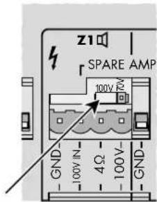
text_image
z1 SPARE AMP 100V 70V GND 100V IN 4Ω 100V- GND⑦ Jumper for the rated output voltage
2) Rearrange the jumper according to the desired voltage:

70 V rated output voltage

100 V rated output voltage
5.2 Microphones
Microphones with an XLR or 6.3 mm plug may be connected to the combined XLR/6.3 mm jacks (28) of the inputs CH 1 to CH 3:
1) Turn the control for the input amplification GAIN (29) towards "MIC". If required, re-adjust the control during operation. (If an announcement via this input is too low, turn the control clockwise; if the announcement is distorted, turn the control counter-clockwise.)
2) If a microphone requires phantom power, press down the switch PHANTOM POWER (27). The phantom voltage is only available at the XLR contacts of the jack.
CAUTION!
- Only actuate the switch with the unit switched off or with the input muted (switching noise).
- Never connect an unbalanced microphone when phantom power (15V) has been activated; otherwise, the microphone may be damaged.
5.3 Audio sources with line level
1) Connect units with a mono output to the combined XLR/6.3 mm jacks (28) of the inputs CH1 to CH3. Turn the control for the input amplification GAIN (29) towards "LINE". If required, readjust the control during operation. (If the signal via this input is too low, turn the control clockwise; if the sound is distorted, turn the control counter-clockwise.)
Disengage the switch PHANTOM POWER (27) if the audio source does not explicitly require phantom power (phantom voltage only at the XLR contacts of the jack).
The jacks are designed for balanced signals. Audio sources with unbalanced signals may be connected via 2-pole 6.3 mm plugs or via an XLR plug with the contacts 1 and 3 connected. Of course they may also be connected to one of the RCA jacks (24) of the channels CH4 or CH5.
The input channels CH1 to CH3 have medium priority, i. e. their input signals take priority over the channels CH4 and CH5, but they are interrupted by announcements via the zone-paging microphones PA-4000RC, the desk microphone PA-4000PTT or an emergency microphone PA-4000FMP.
For input signals which require the highest priority, use the input PAGING (30) with plug-in screw terminals (e. g. for a micro-
phone with preamplifier or the line level output of a telephone system).
2) Connect units with a stereo output (e.g. CD player) to the RCA jacks (24) of the inputs CH4 to CH5. Both stereo channels are mixed to a mono signal in the amplifier.
These inputs take the lowest priority and are automatically muted by a signal at a higher- priority input (table fig. 6 in chapter 3).
5.4 Desk microphone PA-4000PTT
With this desk microphone (separate accessory), announcements of highest priority can be made. The PA zones where these announcements should be heard are selected at the amplifier.
Connect the PA-4000PTT, e. g. with the supplied cable, to the RJ45 jack PTT (32). The length of the cable must not exceed 30 m.
5.5 Zone-paging microphone PA-4000RC
With the zone-paging microphone (separate accessory), announcements of high priority can be made. In each case it is possible to select at the PA-4000RC in which PA zone the announcement is to be heard. Up to 32 PA-4000RC units can be connected to a PA-40120.
5.5.1 Installing a connection module
It is necessary first to install the connection module supplied with the PA-4000RC into the amplifier. Figure 2 shows the amplifier with the module installed. The connection module has two RJ45 jacks (33) to which one PA-4000RC each may be connected. To each zone-paging microphone, a further microphone may again be connected until 32 zone-paging microphones as a maximum and the amplifier are connected with each other.
1) Unscrew the two screws of the cover plate (on the rear side of the amplifier on the very right) und remove the plate.
2) If only the jack INPUT 1 of the two jacks (33) is used, the jumper on the PCB of the connection module must be placed to position ON for a correct termination of the line. If both jacks are used, the jumper must be placed to position OFF (fig. 8).
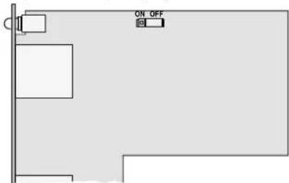
text_image
ON OFF⑧ Connection module for PA-4000RC with jumper for the terminating resistor
3) Slide the module into the opening on the rear side of the amplifier. Make sure that the connector on the module correctly fits into the socket in the amplifier. Fasten the module with the two screws.
5.5.2 Connecting zone-paging microphones
1) Connect a jack of the module, e. g. via the supplied cable, to the RJ45 jack LINK (47) of the (first) PA-4000RC. If required, connect the jack INPUT (46) to the jack LINK of another PA-4000RC etc., until all units are connected. The total length of the line must not exceed 1000 m.
2) To prevent interference during signal transmission, make sure that the termination of the line is correct. Set the switch TERMINATION of the DIP switch block (44) to the lower position (ON) at the last unit of the chain (or at the two last units if INPUT 1 and INPUT 2 are used at the module). For all other units the switch must remain in the upper position.
3) With a total cable length above 500 m (for each input at the connection module) or if more than 10 PA-4000RC units are connected, the power supply via the PA-40120 is not sufficient. In this case connect an additional power supply unit with = 24 V to the 11 ^th PA-4000RC unit or the zone-paging microphone which has a connection of more than 500 m.
Connect the power supply unit to the jack 24V= (43). The required dimensions of the low-voltage plug are 5.5 / 2,1 mm (outside / inside diameter). The polarity is as desired.
The supply voltage is also routed to the zone paging microphones that are connected to the jack INPUT (46). Thus, these zone paging microphones do not require a power supply unit of their own if the first power supply unit provides sufficient current (current consumption of each PA-4000RC: 63 mA).
5.5.3 Adjusting the addresses of the units
To enable communication between the amplifier and the zone paging microphones, the PA-4000RC connected must have different data bus addresses. To assign the addresses, use the first 5 switches of the DIP switch block (44) located on the rear side of the zone paging microphones. Set the addresses continuously according to the table in figure 9.
Note: Only assign the addresses while the amplifier is switched off; address changes made during operation will not be recognized.
| Addresse | Switch Address | Switch | |
| 1 | |||
| 2 | |||
| 3 | |||
| 4 | |||
| 5 | |||
| 6 | |||
| 7 | |||
| 8 | |||
| 9 | |||
| 10 26 | |||
| 11 27 | |||
| 12 28 | |||
| 13 29 | |||
| 14 30 | |||
| 15 31 | |||
| 16 32 |
⑨ Address assignment to the PA-4000RC
5.6 Recorder, monitor system
It is possible to connect a recorder or another audio unit with line input (e. g. a monitor system to check the outputs) to the RCA jacks REC (25) or to the 6.3 mm jack MONITOR (26). The RCA jacks are provided for stereo recorders as L (left) and R (right). The amplifier is monophonic; therefore, the signals at the two jacks are identical.
Adjust the selector switch RECORDING / MONITOR (4) on the front side of the unit to define which output signal is supplied.
5.7 Additional amplifier systems
The mixed signals for the respective zone are available as balanced signals with line level at the plug-in screw terminals PRE OUT (22). Here additional amplifier systems for PA applications in a larger area may be connected.
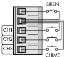
5.8 Momentary pushbutton for chime activation, switch for siren
By means of a normally open contact, a chime may be added to the signals of each of the inputs CH1 to CH3. Three different types of sound can be selected (chapter 5.8.1). To activate the chime, connect e.g. a momentary pushbutton to the corresponding contact of the plug-in screw terminals CH1/CH2/CH3 (31) and the common contact (2nd contact from above) [fig. 10].
For a siren sound of high volume in all zones, connect the upper two contacts of the plug-in screw terminals via a switch. Contrary to the sounds of the chime which end automatically shortly after actuating the respective momentary pushbutton, the siren can only be heard as long as the switch is closed.
text_image
SIREN CH1 CH2 CH3 CHIME⑩ Connection of momentary pushbuttons of chime/siren switch
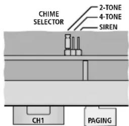
5.8.1 Selecting the sound of the chime
The sound of the chime can be adjusted inside the amplifier. A 2-tone sequence, a 4-tone sequence and a siren sound are available. The siren sound is an emergency signal according to DIN 33 404 / EN 457 and independent of the siren function via the siren switching contact described above.
1) Remove the housing cover of the amplifier.
2) A PCB with a jumper is provided in the rear area, in parallel to the rear side of the unit, near the inputs for CH1 and PAGING. Place the jumper on the position corresponding to the desired sound (fig. 11).
text_image
CHIME SELECTOR 2-TONE 4-TONE SIREN CH1 PAGING⑪ Selection of the sound of chime
3) Close the housing with the cover.
5.9 Unit for evaluating a failure of the unit
If an amplifier output fails to operate or if a fault occurs in one of the connected emergency microphones, the relay FAULT (18) is switched. Here, a unit for evaluating the fault, e. g. a signal device, can be connected. The relay is equipped with a float switch contact and has a rating of 24 V/500 mA.
5.10 Reserve amplifier
Any failure of the power amplifier output are automatically recognized, and a relay will switch over to an additional amplifier. This is only possible if the 100 / 70 V output of the PA-40120 is used.
1) Connect the input of the reserve amplifier to the plug-in screw terminals PRE OUT (22) of the desired output.
2) Connect the 100 / 70 V output of the reserve amplifier to the contacts 100 V IN and GND of the corresponding plug-in screw terminals (20).
5.11 Emergency microphone unit PA-4000FMP
With this separately available accessory, emergency announcements can be made at highest priority. In addition, the emergency microphone unit allows to record an announcement which is automatically reproduced in an emergency situation via the amplifier system (for details instructions on the PA-4000FMP).
Connect a PA-4000FMP to the RJ45 jack EMERGENCY IN (23) for the corresponding PA zone. The cable length may be 1000 m as a maximum. For a cable length of more than 500 m, the PA-4000FMP must be supplied with power via a power supply unit of its own (instructions on the PA-4000FMP).
5.12 Emergency priority relays
Emergency priority relays are designed to bridge volume controls inserted between the amplifier and the speakers so that emergency announcements are transmitted everywhere at maximum volume. For each PA zone (Z1 to Z4) of the PA-40120, an output 24 V=EMER. OUT (21) is available for connecting emergency priority relays. The rating of each output is 200 mA.
The switching voltage is released when an emergency microphone unit PA-4000FMP signals an emergency situation for this PA zone.
5.13 Power supply and emergency power supply
For continued operation of the amplifier in case of mains failure, connect a 24 V emergency power supply unit to the terminals 24 V= (19) [e. g. PA-24ESP from MONACOR]. Finally connect the plug of the mains cable (16) to a socket (230 V/50 Hz).
Notes:
- When a 24 V voltage is available, the amplifier is immediately in operation and the power LED (14) and the LEDs PWR (3) of the four outputs light up. The amplifier cannot be switched off with the switch POWER (15). The switch can only be used to switch between mains power supply and emergency power supply.
- During emergency power operation, the amplifier supplies less power than during mains operation.
6 Operation
1) To prevent an excessive volume, turn the output controls Z1 to Z4 (11) to "0" prior to the first switching-on.
2) First switch on the audio sources connected, then switch on the PA-40120 with the POWER switch (15). The power LED (14) and the LEDs PWR (3) of the four output amplifiers light up. If additional amplifier systems for PA applications are connected to the PA-40120, switch them on last.
After operation, switch off the units in reverse order:
- the additional amplifier systems
- the PA-40120
- the audio sources connected
The amplifier has a switch-on delay: approx. one second after switch-on, the speakers are ready for operation. For this time the LEDs PROTECT (3) of the four outputs light up.
3) For a basic settings, first turn all controls for the inputs LEVEL (9) and PAGING / PTT (13) to the left stop and set the tone controls (1) to mid-position.
4) Turn up the controls for the outputs Z1 to Z4 (11) used so far that the following adjustments can well be heard via the speakers.
5) Switch on the input channels used with the switch CH ON (10). The LED above the switch lights up with the channel switched on. Use the switches Z1 - Z4 (2) to define for each input to which outputs (i. e. PA zones) its signal shall be routed. The LED SIG (8) lights up when a signal of sufficient strength is available at the input. If the LED does not light up, increase the output level of the audio sources or readjust the input gain for the channels CH1 to CH3, using the control GAIN (29) located above the respective input jack.
Mix the input signals with the corresponding volume controls LEVEL (9) or fade them in and out as required.
If an audio source is not used, switch off its input channel with the switch CH ON (10).
6) Adjust the desired volume for the respective PA zone with the output controls Z1 to Z4 (11).
CAUTION

Never adjust a very high speaker volume. Permanent high volumes may damage your hearing! Your ear will get
accustomed to high volumes which do not seem to be that high any more after some time. Therefore, do not further increase a high volume after getting used to it.
To prevent a feedback noise, do not hold a microphone towards a speaker or too close to it. Likewise, feedback noise may occur when the volume adjustment of the speakers is too high. In this case, attenuate the microphone volume, using the respective control LEVEL.
The level of the respective output is indicated by the LEDs -10, -6, 0 dB and CLIP (3). If the LED CLIP lights up, the amplifier is overloaded. In this case turn back the control (11) for this output correspondingly or attenuate the volume of the corresponding input signal with the control LEVEL (9).
7) Adjust the sound with the controls (1) TREBLE for the high frequencies and BASS for the low frequencies. If required, readjust the volume afterwards.
6.1 Checking the outputs
Via the integrated speaker (7) or a monitor system connected to the jack MONITOR (26), the signals of the outputs can be checked.
1) Use the rotary switch RECORDING MONITOR (4) to select the output to be checked. In position OFF no output has been selected.
2) Use the switch SPEAKER (5) to define if the internal speaker (7) should be used (button pressed down) or not (button disengaged).
3) Adjust the desired volume with the control LEVEL (6).
Notes:
- The output jacks REC (25) receive the same signal as the jack MONITOR (26).
- If no outputs are to be checked via the speaker (7) but warning signals are to be heard in case of fault, do not switch off the speaker with the switch SPEAKER (5) but set the rotary switch RECORDING/MONITOR (4) to position OFF or turn back the volume with the control LEVEL (6). The control has no effect on the volume of the warning signals.
6.2 Activating the chime
For the chime to sound, e. g. to precede an announcement via one of the inputs CH1 to CH3, briefly press the corresponding momentary pushbutton connected to the terminals (31) [ chapter 5.8]. The chime is added to the input signal but its volume does not depend on the control LEVEL (9) of the input channel; it only depends on the volume adjustment of output (11).
Like the announcements made via the inputs CH1 to CH3, the input signals of the input channels of lower priority, CH4 and CH5, are muted while the chime sounds.
6.3 Siren
For a siren sound of high volume in all PA zones, actuate the switch connected to the terminals (31) [ chapter 5.8]. Contrary to the chime which ends automatically, the siren can be heard until switching-off.
The siren volume is independent of the volume controls for the outputs (11) and cannot be changed.
6.4 Desk microphone PA-4000PTT
For announcements with this desk microphone:
1) Select with the switches ZONES SELECTOR (12) on the amplifier in which PA zones the announcement should be heard. Press the switches of the desired zones, disengage the other switches.
2) Turn up approx. halfway the control for the volume LEVEL-PAGING / PTT (13) on the amplifier prior to the first announcement.
3) Keep the TALK button (37) pressed at the microphone and talk into the microphone cartridge (35). The LED indicator (36) lights up. When is exceeded, a certain talk volume, the input signals of lower priority are automatically muted at the amplifier (table fig. 6 in chapter 3, page 12).
4) If required, readjust the volume of the announcement with the control LEVEL-PAGING / PTT. The volume controls for the outputs (11) have no effect.
6.4.1 Adjustments at the PA-4000PTT
There are two small switches on the rear side of the desk microphone:
PRIORITY – for use at the PA-40120, leave this switch in the upper position, as the priority for this microphone is defined in the amplifier (for a better intelligibility of an announcement, the other input signals are muted as soon as talking starts or the chime sounds)
CHIME – in position ON, first a chime sounds when pressing the TALK button (37); the sound of the chime is the same as if activated via a momentary pushbutton connected to the amplifier. It can be selected in the amplifier (chapter 5.8.1)
6.5 Announcement via the input PAGING
For an announcement via a unit connected to the input PAGING (30) [e. g. microphone with preamplifier or the line level output of a telephone system], proceed as described in chapter 6.4. The adjustments apply likewise to the desk microphone PA-4000PTT and the input PAGING. A signal at the input PAGING will also mute the input signals of lower priority. It is mixed with the signal of the desk microphone if an announcement is made via the desk microphone at the same time.
6.6 Zone-paging microphone PA-4000RC
For announcements with a PA-4000RC:
1) Turn up approx. halfway the volume control AUDIO LEVEL (48) on the rear side of the zone-paging microphone prior to the first announcement.
2) With the buttons under Z1 to Z4 (50), preselect the PA zones in which the announcement is to be heard. The LED BUSY next to the button lights up for the zones selected.
To deselect a zone, press the corresponding button again so that the LED BUSY extinguishes. To select and deselect all zones, press the button ALL CALL (51).
If the BUSY LEDs flash, an announcement via another zone-paging microphone is being made in the corresponding PA zones. A simultaneous announcement via several zone-paging microphones is not possible (not even if different zones are to be addressed).
If the current announcement via a zone-paging microphone of higher or the same priority is made, wait for the end of this announcement. An interruption of the announcement is only possible by a microphone of higher priority (to adjust the priority chapter 5.6.2).
3) Keep the TALK button (52) pressed and talk into the microphone cartridge (49). The LED indicator above the button lights up. When pressing the button, the input signals of lower priority are automatically muted at the amplifier (table fig. 6, chapter 3, page 12).
4) If required, readjust the volume of the announcement with the control AUDIO LEVEL (48). The volume controls for the outputs (11) have no effect.
6.6.1 Status LEDs at the PA-4000RC
In addition to the LEDs BUSY and TALK described above, the zone-paging microphone is equipped with the following status LEDs:
POWER / CPU ERROR (40) – lights up as soon as the supply voltage is available; it flashes in case of a malfunction of the microprocessor in the PA-4000RC
MIC FAULT / LOW VOLTAGE (41) – lights up with a failure of the microphone, it flashes if the supply voltage is too low; in case the supply voltage is too low, the connection of an additional power supply unit may help (Chapter 5.5.2, item 3)
SIGNAL (42) – lights up when a microphone signal is available
EMER. (50) – (one for each PA zone) light up when an emergency microphone unit PA-4000FMP signals an emergency situation for the corresponding zone
6.6.2 Adjustments at the PA-4000RC
The DIP switch block (45) with the three switches on the rear side of the desk microphone offers the following functions:
CHIME – in position ON, a chime sounds first when the TALK button (52) is pressed; the sound of the chime is the same as if activated via a momentary pushbutton connected to the amplifier. It can be selected in the amplifier ( chapter 5.8.1)
PRIORITY – in position ON, the PA-4000RC takes priority over others without this function activated and it is able to interrupt their announcements
COMPRESSION – in position ON, the dynamic power of the microphone signal is attenuated and thus distortions are reduced when talking at high volume
7 Protective Circuits and Fault Indication
The output amplifiers of the PA-40120 are equipped with protective circuits against overload and overheating to prevent damage to the speakers and the amplifier. In case an output amplifier fails in this way, a relay will switch the 100 V speakers to a connected reserve amplifier (Chapter 5.10). The Protect LED (3) of the output concerned lights up and a warning signal sounds via the internal speaker (7). In addition, the relay FAULT (18) responds and is therefore able e.g. to control an external warning facility. Short lighting-up of all PROTECT LEDs when switching on the amplifier is usual and does not indicate any defect.
If a fault occurs at a connected emergency microphone unit PA-4000FMP (e.g. at the handheld microphone of the microphone system), likewise a warning signal sounds via the internal speaker (7) and the relay FAULT (18) responds. In addition, the LED EMER. FAULT (3) of the PA zone the emergency microphone unit is assigned to lights up.
In order to be able to hear the warning signal via the internal speaker (7), the speaker must be switched on [switch SPEAKER (5) engaged]. The control LEVEL (6) has no effect on the volume of the warning signal.
8 Specifications
8.1 Amplifier PA-40120
RMS output power: 4 × 120 W
Peak output power: 4 × 170 W
Frequency range: 45–20 000 Hz (−3 dB)
S/N ratio
via LINE input: .... > 90 dB (A filter)
via MIC input: ....>70 dB (A filter)
(input sensitivity, impedance, type of connection)
"MIC": 2.5mV, 5kΩ, balanced
"LINE": 245 mV, 15 kΩ, balanced
Inputs CH4–CH5
RCA jacks: 245 mV, 15 kΩ,
unbalanced
Input PAGING: 245 mV, 10 kΩ, balanced
Output REC OUT: 775 mV, 3 kΩ, unbalanced
Output MONITOR:....775 mV, 200 Ω, unbalanced
Outputs PRE OUT: 775 mV, 200 Ω, balanced
Output FAULT:.... relay with switch contact (24V/500mA max.)
Outputs 24V== EMER. OUT:.. 24V/200mA to switch emergency priority relays
Tone controls
BASS:....±10dB/100Hz
TREBLE: .... ± 10dB/10 kHz
Power supply
Mains operation: ..... 230V/50Hz
Power consumption: .... 1500VA max.
Emergency supply:....==24V
Current consumption: ... 40A max.
Ambient temperature: ..... 0–40°C
Dimensions (W × H × D): ... 482 × 90 × 377 mm, 2 rack spaces
Weight: 22.1 kg
Pin configuration
of the input jacks CH 1 to CH 3 (28) XLR

1 = ground
2 = signal + (+15 V phantom power)
3 = signal - (+15 V phantom power)
6.3 mm connector

T = signal +
R = signal -
S = ground
Pin configuration of the jack MONITOR (26)
6.3 mm connector

T = signal
S = ground
8.2 Zone-paging microphone PA-4000RC
Power supply: ·s·s=24 V(16-35 V) via PA-40120 or PSU
Current consumption
Operation: 63 mA
Stand-by: 57 mA
Audio output
Rated level: 245 mV
Impedance: 600 Ω
Type of connection: ..... balanced
THD: .... < 0.5%
S/N ratio: .... > 60 dB
Frequency range: 150-15 000 Hz (-3 dB)
Dimensions (W × H × D): ... 110 × 48 × 155 mm
Weight: 900 g
Connection:
RJ 45
Max. number of units: ..... 32
Total connection length: .... 1000 m max.
Note: For a total cable length above 500 m or if more than 10 PA-4000RC units are connected, an additional power supply unit is required for power supply.
Subject to technical modification.