
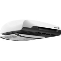
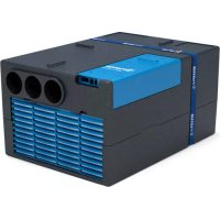
Aventa eco - Air Conditioning TRUMA - Free user manual and instructions
Find the device manual for free Aventa eco TRUMA in PDF.
| Product type | Roof air conditioning for motorhomes and caravans |
| Brand | Truma |
| Model | Aventa eco |
| Power supply | 230-240 V~, 50 Hz |
| Power consumption (cooling) | 2.8 A |
| Starting current | 20 A (150 ms) |
| Cooling capacity | 1.7 kW |
| Maximum air flow | 340 m³/h |
| Weight | 28 kg |
| Cut-out dimensions | 350 × 380 mm or 400 × 400 mm |
| Operating temperature range | -16 °C to 40 °C |
| Maximum tilt during operation | 8 % |
| Refrigerant | R407C, PRP 1774, CO₂ equivalent 674.1 kg |
| Main functions | Cooling, automatic, circulation air, sleep, timer, ambient lighting |
| Timer | Yes, adjustable from 15 min to 24 h |
| Remote control | Infrared, with wall mounting bracket |
| Maintenance | Replace filters every 12 months maximum; clean exterior with a soft, damp cloth |
| Manufacturer warranty | 24 months in the EU (consumer) |
| Optional accessories | Truma CP plus, iNet Box, 12 V adapter for lighting, filters, sealing frame |
| Safety | Installation and repair only by a specialist; all-pole circuit breaker mandatory |
Frequently Asked Questions - Aventa eco TRUMA
User questions about Aventa eco TRUMA
0 question about this device. Answer the ones you know or ask your own.
Ask a new question about this device
Download the instructions for your Air Conditioning in PDF format for free! Find your manual Aventa eco - TRUMA and take your electronic device back in hand. On this page are published all the documents necessary for the use of your device. Aventa eco by TRUMA.
USER MANUAL Aventa eco TRUMA
Operating instructions Installation instructions
To be kept in the vehicle!
Page
Page

Safety instructions 14
Notes on using air conditioning systems 15
Operating instructions
Remote control 16
Start-up 17
Switching on 17
Mode 17
Fan 17
Sleep function 17
Switching off 17
Time 17
Timer ON/OFF 17
Ambient lighting 17
Reset 17
Resend 17
Setup 17
IR receiver and manual on / off 18
IR receiver / function indicator 18
RedLEDilluminates 18
Air Distribution 18
IR remote control battery change 18
Maintenance 18
Disposal 18
Accessories 19
Troubleshooting 19
Technical data 19
Installation dimensions (in mm) 20
Clearance around the air conditioning system 20
Air inlets / outlets 20
Condensation traps 20
Manufacturer's Warranty
(European Union) 20
Installation instructions
Scope of delivery 21
Accessories for installation (optional) 21
Intended use 22
Selecting a location 22
Cut-out installation 400 x 400 22
Installation with new cut-out 22
Preparation for power cable connection 23
Securing the device 23
Use of roof thickness adapters 23
Inserting the filters 24
230 V electrical connection 24
Function test /
remote control mounting 24
Symbols used
The device must only be installed and repaired by an expert.
Symbol indicates a possible hazard.
Note containing information and tips.
Safety instructions
Repairs may only be carried out by an expert!
To avoid transportation damage, the device may only be sent to the Truma Service Centre if agreed beforehand.
The power supply must be disconnected from the mains (all poles) before opening the housing.
The device fuses and connection cables must only be replaced by experts.
The 230V , T 5 A H (slow) device fuse can be found on the electronic control unit in the device and must always be replaced with an identical fuse.
Guarantee claims, warranty claims and acceptance of liability will be ruled out in the event of the following:
- modifications to the device (including accessories),
- failure to use original Truma parts as replacement parts and accessories,
- failure to follow the installation and operating instructions.
It also becomes illegal to use the appliance, and in some countries this also makes it illegal to use the vehicle.
The refrigerant circuit contains R 407C refrigerant and must only be opened in the factory.
The air inlets / outlets at the external unit and the air distributor must not be obstructed under any circumstances. This is essential in order to ensure that your device operates correctly.
In order to avoid damage to the compressor, no uphill or downhill slopes with an incline of more than 8% must be driven on when the device is being operated while driving (e.g. with generator or voltage converter).
Do not operate the device in cooling mode for long periods with the vehicle at an angle, since the condensation that is produced may not be able to run away and may penetrate the vehicle if the circumstances are unfavourable.
For problem-free operation and in order to avoid damage, the supply voltage must always come from a source with a sine wave curve (e.g. voltage converter, generator) and without voltage spikes.
When the vehicle is being cleaned it must be ensured that no water gets into the device when spraying with a high-pressure cleaner, for example (do not spray directly into the openings of the device).
Hot cleaners and steam cleaners must not be used.
The condensation traps must be clear at all times during operation.
Notes on using air conditioning systems
The air conditioning system is designed for power input of up to 2.8 A. You should still check whether the camp site has adequate fuse protection (min. 4 A) before starting the equipment up.
Park the vehicle in the shade if possible.
Darkening with blinds reduces the amount of heat insolation.
Clean your roof at regular intervals (dirty roofs heat up more than clean roofs).
Ventilate your vehicle well before starting the equipment in order to remove accumulated warm air from the vehicle.
In order to obtain a healthy room climate, the difference between the inside and outside temperatures should not be too great. The recirculated air is cleaned and dried during operation. A pleasant room climate is produced by drying the moist air, even with small temperature differences.
Keep all doors and windows closed during cooling operation so that no condensation build-up occurs at the air distributor.
For faster cooling:
- Move fan level to high,
- Move front / rear air distribution to centre position,
- Set floor / ceiling air distribution to ceiling.
Operating instructions
Operating instructions can be viewed in offline mode with a mobile device and the Truma App. Download the operating instructions when you have a WiFi connection and save them on your mobile device.
The symbols in the display are visible depending on the settings.
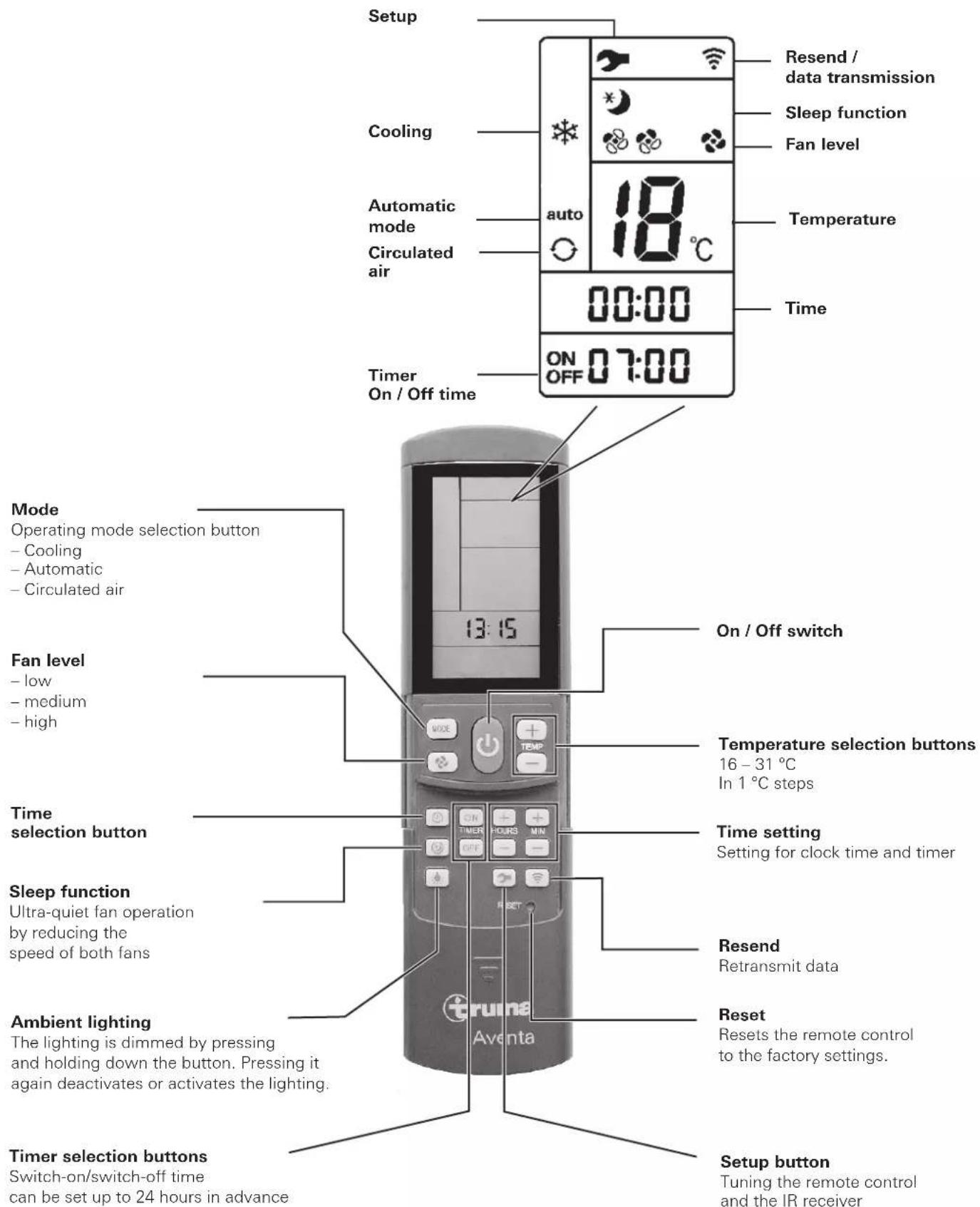
Remote control
Fig. 1
Start-up
Before switching on, be sure to check that the camp site power supply fusing is sufficient (230 V).
In order to prevent the power cable of the recreational vehicle from overheating (minimum cross-section 3 × 2.5 mm^2 ) the cable drum must be fully unwound.
The remote control must always be pointed at the infra-red receiver in order to perform the individual switching commands.
Before switching on for the first time, the remote control must be tuned to the IR receiver.
- Insert batteries (pay attention to polarity)
- Setup symbol flashes
(if symbol does not flash, perform Reset) - Point remote control at IR receiver
- Press Setup button and hold down
- When the red LED on the IR receiver starts to flash, release Setup button.
The remote control is tuned to the IR receiver, the Setup symbol goes off and the air conditioning system starts in circulated air mode, at low fan level and with no timer set.
Switching on
Switch on the air conditioning system using the "On/Off switch" of the remote control. The previous settings are taken over.

The circulated air fan runs after switching on. The com
pressor switches itself on after no more than 3 minutes.
and the blue LED flashes.
Temperature
If necessary, use the "Temperature selection buttons" to set the required room temperature with "+" and "-".
Mode
Select the required operating mode by pressing the "MODE" button one or more times.
- Cooling
Automatic
Circulated air
When the room temperature that was selected using the remote control is reached in cooling mode, the compressor switches off and the blue LED in the IR receiver goes off. The circulated air fan continues to run in order to provide ventilation. If the room temperature setting is exceeded, the device automatically reverts to cooling mode.
The air is dehumidified during cooling. If the air humidity in the vehicle is extremely high at the beginning of the cooling procedure, moisture can build up on the underside of the air distributor. The doors and windows should therefore be kept closed and the highest fan level selected.
In Automatic mode the fan level is selected automatically depending on the room temperature.
In Circulated air mode the interior air is recirculated and cleaned by the filter. No LED's illuminate in the IR receiver.
Fan
Select the required fan level by pressing the "Fan level" button one or more times.
Fan level (not functional in automatic mode):
- low
-medium - high
Sleep function
In "Sleep function" the internal and external fans operate at slow speed and are therefore extremely quiet.
Switching off
To switch off, press the "On/Off switch" on the remote control. The remote control and the device are switched off. The light can still be switched on and off using the "Ambient lighting" button.

If the air conditioning system is switched on again, the
blue LED flashes. The air circulation fan runs, and the
pressor activates itself after no more than 3 minutes.
Time
Press "Time selection button" and set current time using the "Time setting" buttons.
The time is always shown on the display (exception with ON/OFF timer).
The time must be reset after changing the batteries or after a daylight saving time change.
Timer ON / OFF
With the integrated timer the On/Off time of the air conditioning system can be set in advance for a minimum of 15 minutes to a maximum of 24 hours, starting from the current time.
The device must be switched on using the remote control in order to program it.
Set required operating mode and room temperature.
Then select TIMER ON or TIMER OFF using the "TIMER selection buttons". Set the required On/Off time using the "Time setting" buttons (15 minutes to 24 hours) and confirm with TIMER ON and TIMER OFF.
Pressing the relevant timer button again deactivates the timer function.
Ambient lighting
Irrespective of whether the air conditioning system is operating, the lighting in the air distributor can be switched on and off using the "Ambient lighting" button. The lighting is dimmed by pressing and holding down the "Ambient lighting" button. The previous setting is activated when it is switched on again.
Reset
Reset the settings of the remote control to the factory settings when pressed using a ballpoint pen, for example. Setup symbol flashes.
Resend
The previous settings are resent.
Setup
Tune the remote control to the air conditioning system that is going to be operated. Settings set to "Circulated air", fan level low, no timer set.
IR receiver and manual on / off
There is an additional pushbutton on the IR receiver (m), with which the unit can also be switched on and off without the remote control (e.g. with a ballpoint pen).
If the unit is switched on using this pushbutton, the system is automatically reset to the factory settings (automatic mode 22^ ).
IR receiver / function indicator
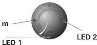
Fig. 2
LED 1 blue - illuminated - (cooling operation)
LED 1 blue - flashing - (cooling operation compressor start-up)
LED 2 red - flashing - (data is being transmitted) LED 2 red - illuminated - (fault)
Red LED illuminates
The device is indicating a fault. Switch device off, wait for a short time and switch on again. If the red LED continues to illuminate, please contact Truma Service.
Air Distribution
Right / left
There are two individually adjustable air outlets at the front and rear.
Front / rear
The air flow can be metered between the front and rear areas of the vehicle.
Ceiling / floor
The air flow can be directed from the ceiling to the floor.
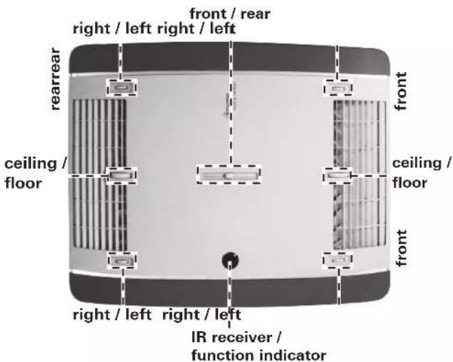
Fig. 3
IR remote control battery change
Only use micro-batteries that will not leak, type LR 3, AM4, AAA, MN 2400 (1.5 V).
The battery compartment is on the rear of the remote control.
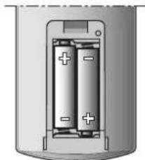
Fig. 4
When inserting new batteries, make sure the positive / negative terminals are connected correctly.
Empty, used batteries can leak and damage the remote control! Remove the batteries if the remote control is not being used for a long period of time.
No warranty given for damage caused by leaking batteries.
Before scrapping the remote control, always remove the batteries and dispose of them properly.

The tuning between the remote control and the air conditioning system is retained if the batteries are removed.
Maintenance
Carry out filter changes depending on the amount of use, but at least every 12 months. Never operate the air conditioning system without a filter. This can lead to loss of power. Keep the air inlets / outlets and the condensation traps free of obstructions such as leaves at all times. Use a soft, damp cloth to clean the air conditioning system.
Disposal
The device must be disposed of in line with the administrative regulations of the respective country in which it is used. National regulations and laws (in Germany, for example, the End-of-life Vehicle Regulation) must be observed.
In other countries, the relevant regulations must be observed.
Accessories
Filter set, 2 pieces (part no. 40091-16800).
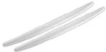
Fig. 5
Truma CP plus
Truma CP plus digital control panel with automatic air conditioning system for the iNet-capable Truma heaters Combi and Truma air conditioning systems Aventa eco, Aventa comfort (from serial number 24084022 - 04/2013), Saphir comfort RC and Saphir compact (from serial number 23091001 - 04/2012)
- The automatic air conditioning system function automatically controls the heater and the air conditioning system until the required temperature is reached in the vehicle.
- With the Truma iNet Box extension, all TIN-Bus-capable Truma appliances can also be controlled via the Truma App.
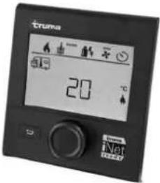
Figure 6
Truma iNet Box
The Truma iNet Box for simple networking and control of Truma appliances with a smartphone or tablet computer using the app.
- Simple installation and start-up via the Truma App
- Can be extended with the update function, which ensures that it is always up to date
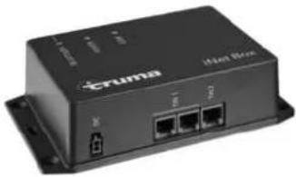
Figure 7
Troubleshooting
Fault Cause / Remedy
Equipment not cooling - Thawing procedure in progress
Device providing insufficient cooling or no cooling at all
- Remote control temperature setting reached or too high
-Filter soiled, change filter. - External air routes soiled / blocked
Moisture on underside of air distributor
- Close windows and doors and select high fan level
Water dripping out of air distributor
- Condensation trap on external unit blocked
Defective seal between device and roof - System at too much of an angle
Remote control not working
- Check batteries in remote control and replace if necessary
Device not reacting to remote control commands
- Check whether there are obstructions between the remote control and the IR receiver
- Is the remote control tuned to the IR receiver? / tune remote control to IR receiver
If these actions do not remedy the problem, please contact Truma Service.
Technical data
Determined on the basis of EN 14511 or Truma test conditions.
Power supply
230V-240V\~,50Hz
Power consumption
Cooling: 2.8 A
Starting current
20 A (150 ms)
Cooling power
1.7 kW
Air volume flow
max. 340m^3 /hr
Usage limits
+16°C to 40°C.
Maximum angle during operation
8%
Weight
28 kg plus installation materials
Dimensions (W× H× D)
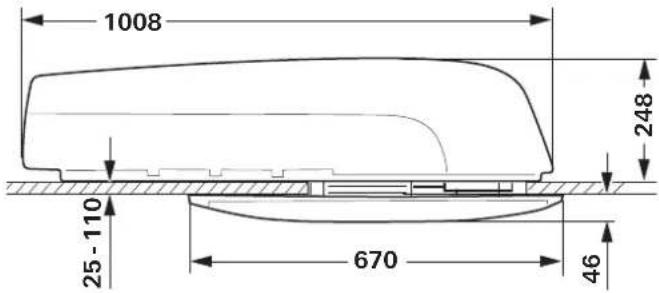
External: 660× 248× 1008mm
Internal: 523 × 46 × 670 ~mm
Refrigerant
R 407C / 0.38 kg
Contains fluorinated greenhouse gases covered by the Kyoto
Protocol. Hermetically sealed
Global warming potential (GWP)
1774
CO2 equivalent
674.1 kg
Right reserved to make technical changes!
Installation dimensions (in mm)
Fig. 8
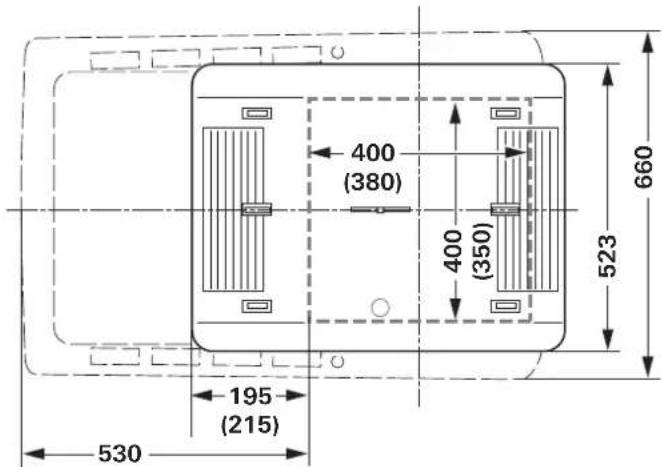
Fig. 9
Clearance around the air conditioning system
The clearance around the external unit must be 20mm at the front and 100mm at the side. At least 30mm of clearance must be left at the rear. Truma recommends clearance of 200mm so that the exhaust air can blow out freely.
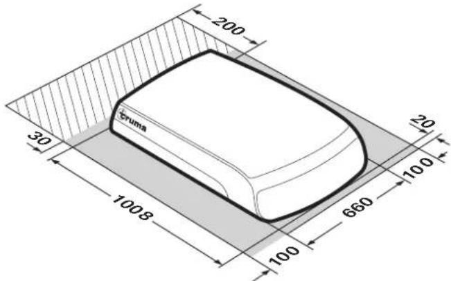
Fig. 10
The clearance around the air distributor must allow the air to blow out without obstructions. The side clearance must be at least 40mm . The pivoting range of flaps and doors must be taken into consideration.
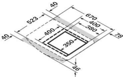
Fig. 11
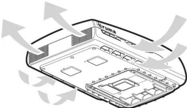
Air inlets / outlets
Fig. 12
Condensation traps
The condensation is led away via the roof of the vehicle.
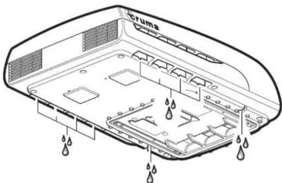
Fig. 13
Right reserved to make technical changes!
Manufacturer's Warranty (European Union)
1. Scope of Manufacturer's Warranty
As the Manufacturer of the unit, Truma undertakes a warranty towards the Consumer that covers any material and/or manufacturing defects of the unit.
This Warranty is applicable in EU member states as well as in Iceland, Norway, Switzerland and Turkey. A Consumer is the natural person who was the first one to purchase the unit from the Manufacturer, OEM or dealer and who neither resold the unit in a commercial or self-employed professional capacity nor did he or she install it for a third party in such a capacity.
The Manufacturer's Warranty covers any of the aforementioned defects that occur within 24 months upon concluding the purchase agreement between the seller and the Consumer. The Manufacturer or an authorised service partner undertakes to remedy such defects through subsequent fulfilment, i.e. at its discretion either by repairing or replacing the defective item. Any defective parts shall become the property of the Manufacturer or the authorised service partner. If the unit is no longer manufactured at the time of defect notification and if replacement delivery has been opted for, then the Manufacturer may deliver a similar product.
If the Manufacturer remedies a defect under its warranty commitment, the term of the Warranty shall not recommence anew with regard to the repaired or replaced parts; rather, the original warranty period shall continue to be applicable to the unit. Only the Manufacturer itself and an authorised service partner shall be entitled to conduct a warranty job. Any costs that occur in the event of a warranty claim shall be settled directly between the authorised service partner and the Manufacturer.
The Warranty does not cover additional costs arising from complicated removal or installation jobs on the unit (e.g. dismantling of furnishings or parts of the vehicle body), and neither does it cover travel expenses incurred by the authorised service partner or the Manufacturer.
No further-reaching claims shall be permitted, especially damage claims presented by the Consumer or third parties. This provision shall not affect the validity of the German Product Liability Act (Produkttaftungsgesetz).
Neither does the voluntary Manufacturer's Warranty affects the Consumer's legally applicable claims for defects towards the seller in the relevant country of purchase. In individual countries there may be warranties that can be issued by the relevant dealer (official distributor, Truma Partner). In such cases the warranty can be implemented directly through the dealer from whom the Consumer bought the unit. The warranty regulations of the country in which the unit was purchased by the Consumer for the first time shall also be applicable.
2. Warranty exclusions
No warranty claim shall be applicable under the following circumstances:
- Improper use, contrary to the specified use
- Improper installation, assembly or commissioning, contrary to operating or installation instructions
-
Improper operation, contrary to operating or installation instructions, particularly maintenance, care and warning notes
-
Instances where repairs, installations or any other procedures have been conducted by non-authorised partners
- Consumable materials and parts which are subject to natural wear and tear
- Installation of replacement, supplementary or accessory parts that are not original Manufacturer's parts and which have thus caused a defect
- Damage arising from foreign substances (e.g. oils, plasticisers in the gas), chemical or electrochemical influences in the water, or cases when the unit has come into contact with unsuitable substances (e.g. chemical products, unsuitable cleaning agents)
- Damage caused by abnormal environmental or unsuitable operating conditions
- Damage caused by force majeure or natural disasters or any other influences not within Truma's responsibility
- Damage resulting from improper transport
3. Making a warranty claim
The warranty must be claimed with an authorised service partner or at the Truma Service Centre. All the relevant addresses and phone numbers can be found at www.truma.com, in the "Service" section.
To ensure a smooth procedure, we should be grateful if you could have the following details ready before contacting us:
Detailed description of the defect
Serial number of the unit
-Date of purchase
The authorised service partner or the Truma Service Centre will then specify the further procedure. To avoid transport damage, the affected unit must only be shipped upon prior arrangement with the authorised service partner or the Truma Service Centre.
If the warranty claim is recognised by the Manufacturer, then the transport expenses shall be borne by the same. If no warranty claim is applicable, the Consumer will be notified accordingly and any repair and transport expenses shall then be the Consumer's liability. We must ask you not to send in a unit without prior arrangement.
Installation instructions
Fig. 14
The unit must only be installed and repaired by an expert. Read the installation instructions carefully before commencing the work, and then comply with them!
Scope of delivery
External unit:
-1Aventaeco
-2 brackets
- 4 screws M6 x 70 coated with screw sealant
- 6 screws M6 x 12 coated with screw sealant
-1 base ring
- 2 roof thickness adapters (each 10mm )
-1 remote control with mounting
- 2 screws 2.9 × 16 for mounting
-2 AAA batteries
- 1 set of operating and installation instructions
-1 installation template
-3 Wago clamps
Air distributor (to be ordered separately):
-1 air distributor, fully assembled
Accessories for installation (optional)
Roof thickness adapter 10 mm, 1 pc. (part no. 40091-16900)
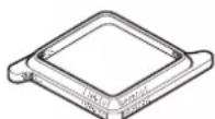
Fig. 15
Sealing frame (part no. 40091-19500)
Recommended for optimum sealing when retrofitting in vehicles with 400 × 400 ~mm cut-out.
Fig. 16
Covering tape
cream (part no. 40091-31200)
grey (part no. 40091-31300)
For compensating for a gap of up to 5mm between air distributor and roof.
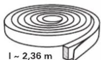
Fig. 17
12 V adapter for air distributor lighting
1 pc. (part no. 40091-33000)
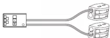
Fig. 18
Intended use
This device has been designed for installation in motor homes and caravans and is intended for use in the private sector. Other applications are only permitted after prior consultation with Truma.
Selecting a location
After the roof air conditioning system has been installed, any exhaust cowl that is in the vicinity must protrude at least 10 cm over the air conditioning system. The exhaust cowl must be extended if necessary (pay attention to the heater manufacturer's specifications).
The roof of the vehicle (roof thicknesses of 25 to 110mm must be level and smooth.
Three installation options are available:
- The cut-out must be a new cut-out (350 x 380 mm)
Cut-out of an existing roof hatch (400× 400mm) without a
sealing frame (accessory).
- Cut-out of an existing roof hatch (400 x 400 mm) with a sealing frame (accessory). The installation instructions are included with the sealing frame.
Attention must always be paid to the following points:
-
The device should be installed as close as possible to the centre of the vehicle.
-
Check that no obstructions are present that will hinder installation.
-
There may be electrical cables running between the interior and the exterior of the roof. Disconnect all voltage sources before starting the work (all poles).
-
The roof load must not be exceeded (see vehicle manufacturer's specifications).
-
Check interior installation site for obstructions.
-
A wooden reinforcing frame (min. 25mm ) must be installed around the roof cut-out between the upper and lower surfaces of the roof. The insulation may have to be removed.
When the skylight with safety ventilation is replaced by the air conditioning system, it must be ensured that the safety ventilation is restored in another suitable location.
Cut-out installation 400 × 400
For optimum sealing we recommend the use of the sealing frame that is available as accessory (part no. 40091-19000).
For installation with a sealing frame, please refer to the installation instructions provided with the sealing frame.
Installation of the device with an existing roof hatch: the cut-out must be 400 × 400 mm .
Remove existing roof hatch (make cut-out bigger if necessary).
Remove sealant residue and unevenness.
Fill in screw holes with body sealant.
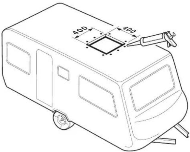
Fig. 19
For the other installation steps, please refer to "Preparation for power cable connection".
Installation with new cut-out
For vehicles without an existing cut-out: required cut-out 350 × 380 mm .
Place template on installation location on vehicle, mark cutout (350× 380mm) and cut it out.
Mark the 4 holes (10 mm) for bracket attachment and drill holes in roof.
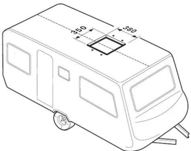
Fig. 20
Preparation for power cable connection
Provide leadthrough for mains cable to connection point, e.g. in the false ceiling.
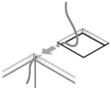
Fig. 21
Move device to roof in a horizontal position and insert into cut-out. The arrow should point in the direction of travel.

Fig. 22
Do not apply additional sealant between the air conditioning system and the roof.
If the device has been turned over or is not horizontal, you must wait for 2 hours before switching on the device.
Push device forwards in cut-out as far as it will go.
Remove protective film from device.
Route mains cable to connection point (lengthen cable with provided Wago clamps if necessary).
If the lighting of the air distributor is also going to be optionally operated using 12V the 12V adapter that is available as an accessory must now be connected. The installation instructions are provided with the 12V adapter.
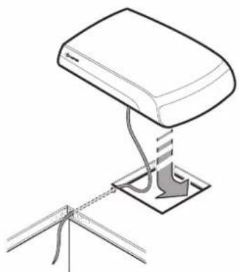
Fig. 23
Securing the device
Screw the two brackets (marked with an arrow in the direction of travel) to the device using the 4 provided M6 x 70 screws (with screw sealant).
Torque 1.8 Nm
If the roof is more than 50~mm thick, M6 screws (length = roof thickness + 30 mm) with tensile strength of 8.8 must be used. The screws must be secured with low-strength screw sealant (e.g. Loctite).
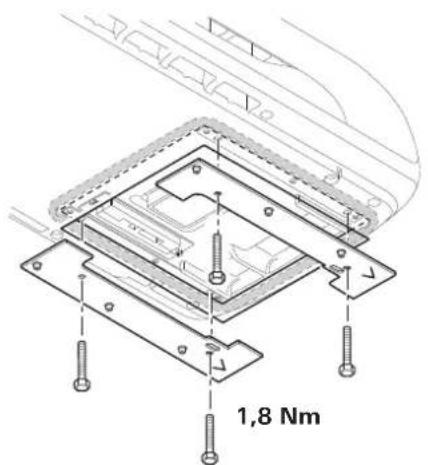
Fig. 24
If the screws are used more than once (e.g. after removal) they must be coated with low-strength screw sealant again (e.g. Loctite) or the screws provided as spare parts used.
Use of roof thickness adapters
Slide in the base ring (1) and, depending on the thickness of the roof, the roof thickness adapters (2 or 2+3 included in scope of delivery) for roof thicknesses of 25 to 50mm into the air distributor as far as they will go. If the roof is thicker, use additional 10mm roof thickness adapters (see accessories). Maximum roof thickness 110mm
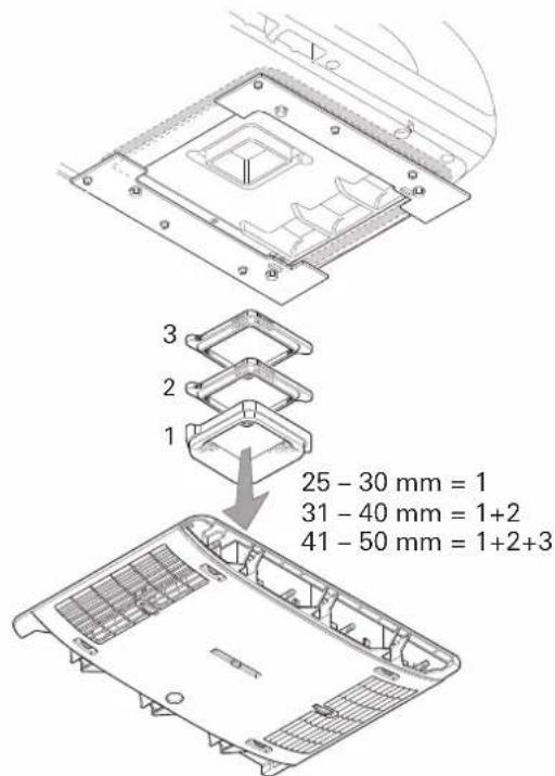
Fig. 25
Securing the air distributor
Connect cable from air distributor to electronic module.
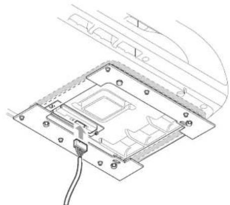
Fig. 26
Screw air distributor (arrow in direction of travel) to bracket with 6 screws M6 x 12 mm.
The covering tape that is available as an accessory can be used to compensate for the gap between the air distributor and the roof.
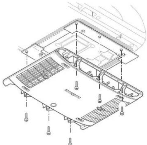
Fig. 27
If the screws are used more than once (e.g. after removal) they must be coated with low-strength screw sealant again (e.g. Loctite) or the screws provided as spare parts used.
Inserting the filters
Insert filters into panels and attach to the air distributor.
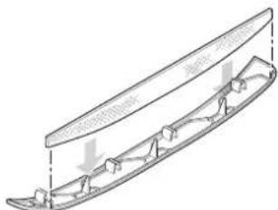
Fig. 28
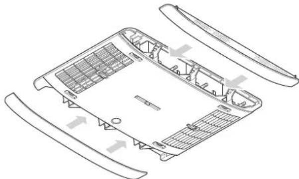
Fig. 29
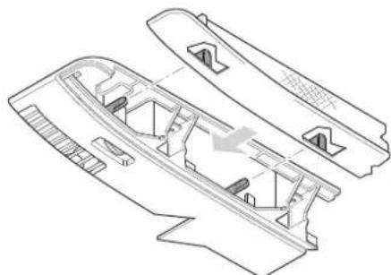
Fig. 30
230 V electrical connection
The 230 V electrical connection must always be made by an expert (in accordance with VDE 0100, part 721 or IEC 60364-7-721, for example, in Germany). The instructions shown here do not constitute a request to non-experts to make the electrical connection, but serve as additional information for an expert who is employed to do the work!
Connect the mains cable that has been routed to the connecting point.
All cables must be secured with clamps!
An insulating device for providing all-pole insulation from the mains with contact clearance of at least 3.5mm must be provided at the vehicle side for carrying out maintenance and repair work.
Function test / remote control mounting
Attach the mounting for the remote control in the required location.
All device functions must subsequently be tested as described in the operating instructions.
The installer must check that the condensation traps are clear after installing the system.
The operating instructions must be handed over to the vehicle owner.
Aventa eco
Table des matieres
Dimensions (I x H x P)
Exterieur:660x248x1008mm
Intérieur: 523 × 46 × 670 ~mm
Réfrigerant
R 407C / 0,38 kg
LED 2 rood - brandt - (storing)
RodeLEDbrandt
Maks. haelding under driften: 8%
Vægt:
28 kg inklusiv monteringsmaterialie
Mäl (b x h x d):
Udvendigt: 660 × 248 × 1008 ~mm
Indvendigt: 523 × 46 × 670 ~mm
Kolemiddel:
R 407C / 0.38 kg
Matt for installationen (matt i mm)
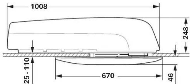
Bild 8
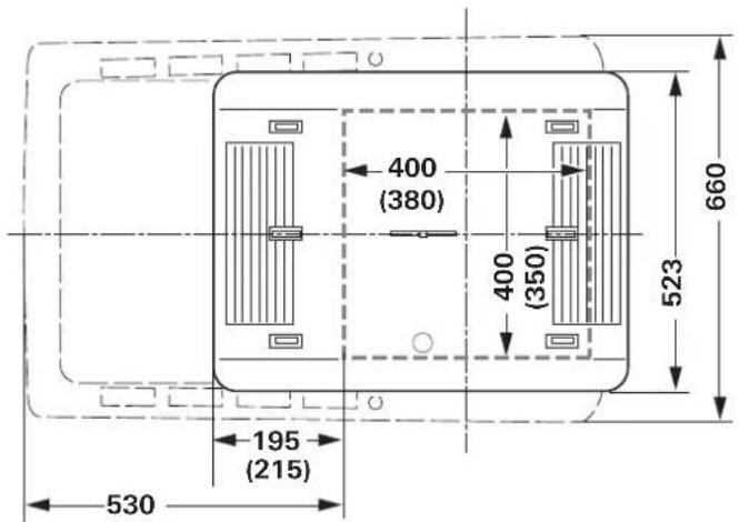
Bild 9
Friytor runt klimatsystemet
Kondensen leads bort over fordonets tak.
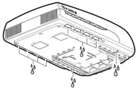
Bild 13
Ratt till tekiska andringar forbehalls!
GB Should problems occur, please contact the Truma Service Centre or one of our authorised service partners (see www.truma.com).
In order to avoid delays, please have the unit model and serial number ready (see type plate).
- Operating instructions Installation instructions
- Operating instructions
- Installation instructions
- Symbols used
- Safety instructions
- Notes on using air conditioning systems
- Start-up
- Switching on
- Temperature
- Mode
- Fan
- Sleep function
- Switching off
- Time
- Timer ON / OFF
- Ambient lighting
- Reset
- Resend
- Setup
- Red LED illuminates
- Air Distribution
- Right / left
- Front / rear
- Ceiling / floor
- IR remote control battery change
- No warranty given for damage caused by leaking batteries.
- Maintenance
- Disposal
- Accessories
- Truma CP plus
- Truma iNet Box
- Troubleshooting
- Fault Cause / Remedy
- Technical data
- Power supply
- Weight
- Refrigerant
- Clearance around the air conditioning system
- Condensation traps
- Manufacturer's Warranty (European Union)
- Scope of Manufacturer's Warranty
- Warranty exclusions
- Making a warranty claim
- Scope of delivery
- External unit:
- Accessories for installation (optional)
- Selecting a location
- Attention must always be paid to the following points:
- Cut-out installation 400 × 400
- Installation with new cut-out
- Preparation for power cable connection
- Securing the device
- Torque 1.8 Nm
- Use of roof thickness adapters
- Securing the air distributor
- Inserting the filters
- V electrical connection
- Function test / remote control mounting
- All device functions must subsequently be tested as described in the operating instructions.
- Aventa eco
- Table des matieres
- Réfrigerant
- RodeLEDbrandt
- Vægt:
- Mäl (b x h x d):
- Kolemiddel:
- Friytor runt klimatsystemet
Brand : TRUMA
Model : Aventa eco
Category : Air Conditioning