
Saphir Vario - Air Conditioning TRUMA - Free user manual and instructions
Find the device manual for free Saphir Vario TRUMA in PDF.
| Product type | Air conditioner for motorhomes and caravans |
| Brand | Truma |
| Model | Saphir Vario |
| Power supply | 230 V - 240 V ~, 50 Hz |
| Power consumption | 1.7 A to 4.4 A (depending on stage) |
| Maximum cooling capacity | 2.0 kW |
| Starting current | 20 A (150 ms) |
| Protection type | IP X5 |
| Maximum cold air flow | 370 m³/h |
| Refrigerant | R 407C and R 134a |
| Operating modes | Cooling (3 stages), ventilation only |
| Cooling power per stage | 600 W (Low), 1500 W (Medium), 2000 W (High) |
| Remote control | Infrared, with temperature and timer settings |
| Shut-off timer | Programmable from 1 to 15 hours |
| Filters | Lint filter and particulate filter |
| Operating temperature | +21 °C to +40 °C |
| Maximum tilt during operation | 5° / 8% |
| Maintenance | Clean lint filter 2 times/year, replace particulate filter once a year |
| Optional accessories | Silencer, drainage channel, flexible suction, TG 1000 sine inverter |
| Usage type | Installation in false floor or rear garage of vehicle |
Frequently Asked Questions - Saphir Vario TRUMA
User questions about Saphir Vario TRUMA
0 question about this device. Answer the ones you know or ask your own.
Ask a new question about this device
Download the instructions for your Air Conditioning in PDF format for free! Find your manual Saphir Vario - TRUMA and take your electronic device back in hand. On this page are published all the documents necessary for the use of your device. Saphir Vario by TRUMA.
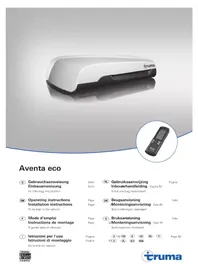
USER MANUAL Saphir Vario TRUMA
To be kept in the vehicle!
FAN = Nur Ventilation
COOL = Kuhlung und
Ventilation
b = FAN
Geblaseleistung
LOW = Niedrig
HIGH = Hoch
c = TEMP.
Gewünschte
Raumtemperatur
16^ bis 31^
d = Keine Funktion
e = TIMER off
600 W = LED 1 (COOL LOW),
1500 W = LED 2 (COOL),
2000 W = LED 1 + LED 2 (COOL HIGH)
Symbols used 12
Safety instructions 12
Notes for the use of air-conditioners 12
Operating instructions
Remote control 13
Taking into operation 13
Switching off 13
Timer off 13
IR receiver and manual on / off 13
Operating indicator 13
RedLEDilluminates 13
Maintenance 14
Trouble-shooting 14
Changing the battery in the remote control 14
Disposal 14
Accessories 14
Operating modes of the TG 1000 sinus power inverter
with the Saphir vario air conditioning unit 15
Operating mode 1 15
Operating mode 2 15
Operating mode 3 16
Technical data 16
Installation dimensions 16
Manufacturer's terms of warranty 17
Installation instructions
Intended use 17
Approval 17
Provisions 17
Location selection 17
Installing the air conditioning unit 18
Cold air distribution and circulating air return feed ... 19
Cold air distribution 19
Circulating air return 19
Installing the infra-red receiver 19
230 V electrical connection and IR receiver
connection 20
Function test / Mounting for the remote control 20
Symbols used

Symbol indicates a possible hazard.

Comment including information and tips.
Safety instructions

Repairs may only be carried out by properly qualified professionals!
In order to avoid transport damage, the device must not be sent until the Truma Service Centre has been contacted.
The voltage must be disconnected at all poles before the housing is opened.
The 230 V, T 5 A H-type (slow, IEC 127) fuse in the unit can be found on the electronic control unit and must always be replaced with an identical fuse.
Appliance fuses and connection leads may only be replaced by a properly qualified person.
Any modifications to the device or the use of spare parts and accessories that are important to the operation of the system that are not original Truma parts and failure to follow the
installation and operating instructions will cancel the warranty and indemnify Truma from any liability claims.
The refrigerant circuit contains R 407C and R 134a refrigerant and must only be opened in the factory.
The cool air outflow and the ambient air suction intake must not on any account be obstructed. Please bear this in mind in order to ensure the trouble-free operation of your device.
The apertures beneath the vehicle floor must be kept free of dirt and snow slush. The apertures must not be located within the area subject to spray from the wheels or mudguards.
Splash protection must be provided if necessary.
If the floor of the vehicle is provided with underfloor protection, all the apertures beneath the vehicle must be covered in order to prevent the spray created from penetrating the device and causing malfunctions. Once the work has been completed the covers can be removed again.
In order to avoid damage to the compressor, when the device is in operation during transit (for example, with the generator or voltage transformer working), do not attempt uphill or downhill gradients of more than 8% .
Do not allow cooling operation to run for extended periods in a tilted position, since the condensation water which forms may not be able to run off, and in the worst scenario might penetrate into the vehicle.
For problem-free operation and in order to avoid damage, the supply voltage must always come from a source with a sine wave curve (e.g. voltage converter, generator) and without voltage spikes.
When the floor of the vehicle is being cleaned, it must be ensured that no water penetrates the openings in the base of the unit when spraying with a high-pressure cleaner, for example.
Notes for the use of air-conditioners
- The Saphir vario air conditioning unit is designed for minimal power consumption. Nevertheless, you should check before taking the system into operation whether the camping site has adequate fuses (min. 1.7 A).
- As far as possible, park your vehicle in the shade.
- Darkening the interior with window blinds and / or a roof awning will reduce the penetration of radiant heat.
- Clean the roof of the vehicle regularly (dirty roofs heat up more readily).
Before operating the device, ventilate your vehicle thoroughly, in order to allow the hot air which builds up inside to escape.
Take care when putting up awnings or similar that there are sufficient openings for the supply air to be discharged. The opening for the hot discharge air should not be on the intake side. - To create a healthy environment on the inside of the vehicle, the difference between the inside and outside temperatures should not be selected as too great. During operation the circulated air will be purified and dried. Due to the drying of the moist, humid air, a pleasant environment will be created inside even with slight temperature differences.
- Keep the doors and windows closed while the cooling system is in operation.
If a single room such as a bedroom is being cooled with 600 W, the two outlets that are not required must be closed, otherwise the cooling power will be distributed throughout the entire vehicle.
Operating instructions
Before starting to use the device, it is essential that the Operating Instructions and "Safety instructions" be read carefully! The vehicle owner is responsible for ensuring that the device can be operated in the proper manner.
Remote control
+/- = Setting
Operating level,
Timer, Temperature
a = MODE
Operating mode
selector switch
FAN = Ventilation only
COOL = Cooling and
ventilation
b = FAN
Blowing power
LOW = Low
HIGH = High
c = TEMP.
Desired interior
temperature
16^ C to 31^ C
d = No function
e = TIMER off
Set timer to 1 to 15 hours
f = RESEND
Send the settings of the remote control to device
again
g = ON / OFF
On/Off switch
Taking into operation
Before switching on, it is essential to make sure that the fuse system for the power supply at the camp site is sufficient (230 V):
600W/1.7A
1500W/3.0A
2000W/4.4A
In order to prevent the power cable for the caravan from overheating (minimum cross-section 3 × 2.5 mm^2 ) the cable drum must be fully unwound.
To carry out the individual switching commands, the remote control must always be pointed at the infra-red receiver.
- Switch the Saphir vario on using button "g" on the remote handset. The "COOL MODE" that was previously selected using the remote handset is automatically used.
- Set the desired operating mode using the button "a".
FAN: Ventilation only (without cooling).
COOL: Cooling with 3 levels.
The blowing power and the interior temperature can be adjusted individually. The green indicator lamps on the receiver indicate compressor operation and therefore cooling operation with three levels.
600 W = LED 1 (COOL LOW),
1500W=LED2(COOL),
2000 W = LED 1 + LED 2 (COOL HIGH)
- If necessary, adjust the fan speed and the room temperature to the required settings using buttons "b", "c", "+" and "-".
When the room temperature that was selected using the remote handset is reached in cooling mode, the compressor switches off and the green indicator lamps in the receiver go out. The circulation fan continues to run in order to provide ventilation. If the room temperature is exceeded the device automatically reverts to cooling mode.
Switching off
To switch off, press the button "g" on the remote control once again.

If the air conditioning unit is switched on again within approximately 3 minutes, the green indicator lamp blinks.
The air circulation fan runs, and the compressor activates itself after 3 minutes.
Timer off
The air conditioning unit deactivation time can be set up to 15 hours in advance using the integrated timer, starting from the current time.
To carry out programming, first switch the device to remote control mode with the switch "g".
Then set the operating mode and the room temperature using buttons "a", "b", "c", "+" and "-".
Then select the required deactivation time (1 - 15 hours) using the "e" button (TIMER).
The programming is not active unless the air conditioning unit is switched on. The remote handset can be deactivated by covering the infrared transmitter on the front of the remote handset. This prevents unintentional air conditioning unit deactivation and accidental deactivation time reprogramming.
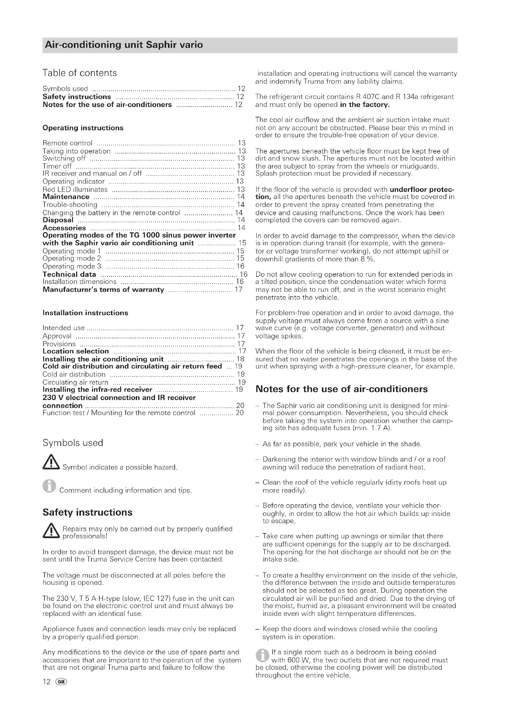
IR receiver and manual on / off
There is an additional pushbutton on the receiver (m), with which the unit can also be switched on and off without the remote control (e.g. with a ballpoint pen).
If the unit is switched on using this pushbutton, the system is automatically reset to the factory settings (COOL, FAN HIGH, TEMP. 21°C).
Operating indicator
LED 1 green (600 W)
LED 2 green (1500 W)
LED 1 and LED 2 (2000 W)
LED 3 red - flashing - (data is being transmitted)
LED 3 red - permanently on - (fault)
Red LED illuminates
The unit is indicating a fault. Switch unit off, wait for a short time and switch on again. If the red LED continues to illuminate, please contact Truma Service.
Maintenance
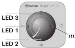
Located on the front side of the unit is a fluff filter (n) and a particle filter (p) for cleaning the air in the room.
The fluff filter (n) must be cleaned at regular intervals, at least twice a year, and replaced if necessary (part no. 40090-64600).
We recommend that the particle filter (p) be replaced annually at the start of the season (part no. 40090-58100).
In order to change the filters, pull fluff filter (n) forward at recesses at side edges and remove from above. Remove particle filter (p) towards the front.

Ensure the installation position is correct. The arrows imprinted on the unit must point towards the inside of the device, and symbolise the direction of flow of the circulating air. The device must never be operated without the filter. Without a filter the evaporator will become dirty, which in turn will impair the performance of the device!
The condensation water drain is located beneath the floor of the vehicle. In order to allow the condensation to drain away freely, check whether the drain is free of dirt, leaves and the like at regular intervals. If this is not done, there is a risk of condensation water penetrating into the vehicle!
Trouble-shooting
Before calling Customer Service, please check the following:
Is the motor home / caravan 230 V power supply lead connected, and are the fuses and circuit breakers OK?
Is the temperature which has been set on the remote control less than the interior temperature?
- Are the fluff filter (n) and the particle filter (p) on the front of the unit or the air intake to the stowage box (in which the unit is installed) free?
Is the air supply opening in the floor of the vehicle free of dirt, leaves and the like?
If this does not solve the problem, please contact the Truman Service.
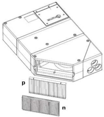
Changing the battery in the remote control
Please be sure to use leak-proof micro-batteries only, type LR 3, AM4, AAA, MN 2400 (1.5 V).
The battery compartment is located on the rear of the remote control unit.
When fitting new batteries, ensure the polarity (positive / negative) is correct!
Dead and used batteries may leak and damage the remote control unit. Remove the batteries if the remote control is not going to be used for an extended period.
No claims under guarantee will be considered for damage caused by leaking batteries.
Disposal
Before disposing of a faulty remote control, always remove the batteries and dispose of correctly.
The device must be disposed of in line with the administrative regulations of the respective country in which it is used. National regulations and laws (in Germany, for example, the End-of-life Vehicle Regulation) must be observed.
Accessories
Noise suppressor for installation in the cold air pipe for additional noise reduction within the living compartment (part no. 40040-60100).
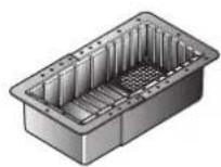
Blow-out channel for additional noise reduction outside the living compartment. Installed beneath the vehicle (part no. 40040-32500).
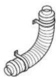
The flexible air conditioning intake allows the air conditioning unit to be installed in a space that is sealed off from the interior (e.g. false floor or rear storage space) and prevents contaminated air from being drawn in (part no. 40040-59100).
TG 1000 sinus power inverter for operating the Saphir vario with 230V from the 12 V battery supply (part no.40090-81000).
Operating modes of the TG 1000 sinus power inverter with the Saphir vario air conditioning unit
The Electrical Kit (part no. 40090-23100) and the Air conditioning Kit (part no. 40090-25900) are required in order to make the electrical connection of the power inverter TG 1000 sinus (part no. 40090-81000). A connecting diagram and a description of the connection are provided with the respective set.
The power inverter is controlled by the air conditioning electronics after the air conditioning unit has been switched on. The air conditioning unit checks the status of the power inverter and the connected electrical supply at short intervals (D+ of alternator, starter battery / auxiliary battery and national network).
If the Saphir vario air conditioning unit is operated with the TG 1000 sinus power inverter, the following operating statuses are possible:
Operating mode 1
via auxiliary battery with 12V
(vehic1 engine off, alternator D + is 0V)
Switch on the Saphir vario air conditioning unit via the remote handset.
If the auxiliary battery voltage is higher than 12 V when the unit is switched on, the Saphir vario air conditioning unit is started.
Regardless of the mode that is selected, the cooling power is limited to the lowest setting in this mode (COOL LOW), even if a higher cooling mode is indicated!
Any fan power setting can be selected. FAN mode (ventilation):
FAN LOW
FAN HIGH
If the auxiliary battery voltage is lower than 12 V, the red LED on the IR receiver illuminates. The air conditioning unit does not start up. Reset by switching the air conditioning unit off.
The air conditioning unit with power inverter cannot be switched on again using the remote handset until the auxiliary battery has been recharged (above 12V - no automatic restart).
If the voltage of the auxiliary battery drops to less than 10.8V while the air conditioning unit is being operated, the air conditioning unit with power inverter is switched off completely to prevent further battery discharging. No red LED therefore illuminates on the IR receiver as a fault indicator.
The air conditioning unit with power inverter cannot be switched on again using the remote handset until the auxiliary battery has been recharged (above 12V - no automatic restart).
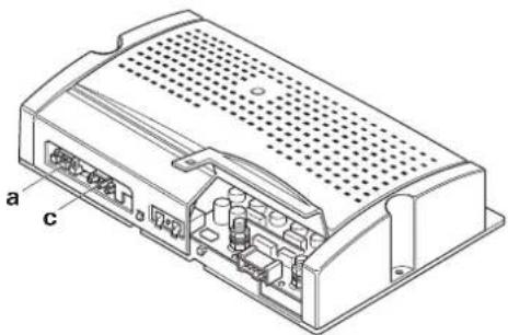
The air conditioning unit with power inverter switches itself off if the connection (a) for the national network input voltage is connected. The red LED on the IR receiver illuminates. The air conditioning unit must be switched off and on again via the remote handset.
When the engine is started the Saphir vario switches to the previously selected cooling mode (COOL LOW or COOL).
Operating mode 2
via alternator with 12 V
(vehic1 engine running,alternator supplies D + = 12V
The auxiliary battery and the starter battery are switched in parallel via the isolating relay. The relay is actuated by D + from the alternator (or D + substitute).
Switch on the Saphir vario air conditioning unit via the remote handset.
If the auxiliary battery voltage is higher than 12V when the unit is switched on, the Saphir vario air conditioning unit is started.
Regardless of the mode that is selected and indicated, the cooling power is limited to the lowest and medium setting in this mode (COOL LOW or COOL), even if a higher cooling mode is indicated!
Any fan power setting can be selected.
FAN mode (ventilation):
FAN LOW
FAN HIGH
Tip
To protect the batteries and limit the use of the alternator charge current, switch electrical consumers off if possible (e.g. switch refrigerator to gas operation).
- The system automatically switches to operating mode 1 when the engine is switched off. If the air conditioning unit is operating at the medium setting (COOL) and the vehicle is switched off, the unit automatically switches to the lowest setting - COOL LOW. When the vehicle is started up again the unit is automatically switched to the COOL setting again if this is still selected on the remote handset. The switchover procedure is controlled by the D+ signal.
- If the auxiliary battery voltage is less than 12V when the system is switched on, the red LED on the IR receiver illuminates. The air conditioning unit does not start up. Reset by switching the air conditioning unit off.
The air conditioning unit with power inverter cannot be switched on again using the remote handset until the auxiliary battery has been recharged (above 12V - no automatic restart).
If the starter battery voltage drops to less than 11.7 V or the auxiliary battery voltage drops to less than
10.8 V during operation, the air conditioning unit with power inverter switches off completely to prevent further battery discharging. No red LED therefore illuminates on the IR receiver as a fault indicator.
The air conditioning unit with power inverter cannot be switched on again using the remote handset until the auxiliary / starter battery has been recharged (above 12 V - no automatic restart).
The air conditioning unit and the power inverter switch themselves off if the input voltage connection (a) for the national network is plugged in. The red LED on the IR receiver illuminates. The air conditioning unit must be switched off and on again via the remote handset.
Operating mode 3
via national network with 230V
The 230V national network is looped through from connector (a) to connector (c) via a relay in the power inverter. The power inverter remains switched off. The air conditioning unit can now be operated at any cooling setting.
The air conditioning unit with power inverter switches itself off in the following cases:
National network failure.
- National network input voltage connector (a) is disconnected.
The red LED on the IR receiver illuminates. The air conditioning unit must be switched off and on again via the remote handset.
If the 230V national network fails, the power inverter is not automatically switched on again in order to prevent unwanted battery discharging.
Technical data
Determined on the basis of EN 14511 and the Truma test conditions.
Designation
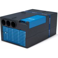
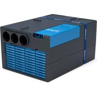
Saphir vario, Comfort air conditioner
Area of operation
Small areas, mobile and stationary
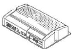
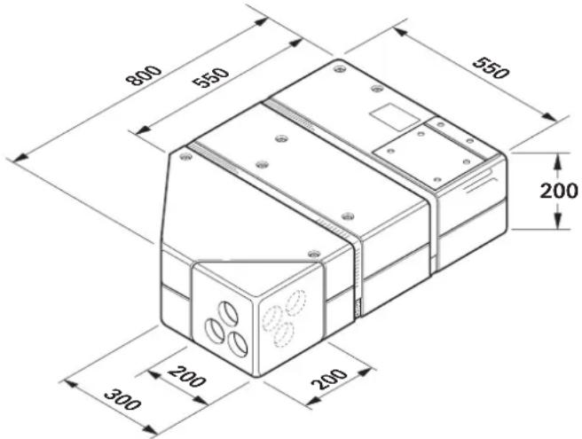
Dimensions (L x W x H)
800× 550× 200mm
Weight
28kg
Power supply
230V-240V\~,50Hz
Maximum cooling capacity
2.0 kW
Start-up current
20 A (150 ms)
Power consumption
1.7A-4.4A
Protection mode
IPX5
Volume flow (cold air)
max. 370m^3 /h
Cooling agent
R 407C and R 134a
Cooling agent content
see name plate on unit
Maximum inclination of vehicle during operation
5^ / 8%
Operational limits
+21°C to +40°C
Below +21^ an ambient air sensor prevents the operation of the compressor.
- An icing sensor prevents impermissible formation of ice on the evaporator.
- A temperature switch pre vents excess current flow and excess temperature at the compressor.
EEC type approval
The Saphir vario complies with the interference suppression directive 72/245/EEC for vehicle engines with annexes
2004/104/EC, 2005/83/EC and 2006/28/EC and bears
type approval number: e1 03 4392
Right to effect technical modifications is reserved!
Installation dimensions
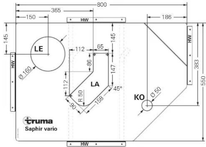
The dimensions are in mm.
Manufacturer's terms of warranty
1. Case of warranty
The manufacturer grants a warranty for malfunctions in the appliance which are based on material or production faults. In addition to this, the statutory warranty claims against the seller remain valid.
A claim under warranty shall not pertain
for parts subject to wear and in cases of natural wear and tear,
- as a result of using components in the units that are not original Truma parts,
- for gas pressure regulation systems as a result of damage by foreign substances (e.g. oils, plasticisers) in the gas,
- as a consequence of failure to respect Truma instructions for installation and use,
- as a consequence of improper handling,
- as a consequence of improper transport packing.
2. Scope of warranty
The warranty is valid for malfunctions as stated under item 1, which occur within 24 months after conclusion of the purchase agreement between the seller and the final consumer. The manufacturers will make good such defects by subsequent fulfilment, i.e. at their discretion either by repair or replacement. In the event of manufacturers providing service under warranty, the term of the warranty shall not recommence anew with regard to the repaired or replaced parts; rather, the old warranty period shall continue to run. More extensive claims, in particular claims for compensatory damages by purchasers or third parties, shall be excluded. This does not affect the rules of the product liability law.
The manufacturer shall bear the cost of employing the Truma customer service for the removal of a malfunction under warranty - in particular transportation costs, travelling expenses, job and material costs, as long as the service is carried out in Germany. The warranty does not cover customer service work in other countries.
Additional costs based on complicated removal and installation conditions of the appliance (e.g. removal of furniture or parts of the vehicle body) do not come under warranty.
3. Raising the case of warranty
The manufacturer's address is:
85640 Putzbrunn, Germany
Always notify the Truma Service Centre or one of our authorised service partners if problems are encountered (see Truma Service book or www.truma.com). Please describe you complaint in detail and state the factory number of the device and the purchase date.
In order for the manufacturer to be able to determine whether an incident subject to guarantee has occurred, the end user must, at his own risk, bring or send the device to the manufacturer. If there is damage to heat exchangers, the gas pressure regulator must also be sent back to the factory.
Air conditioners:
To avoid transportation damage, the unit may only be sent to the Truma Service Centre Germany or one of our authorised service partners if agreed beforehand. Otherwise the sender bears the risk for any transportation damage.
Please send all shipment to the factory as freight. In cases under guarantee, the works shall bear the transport costs or the costs of delivery and return. If the damage is deemed not to be a warranty case, the manufacturer shall notify the customer and shall specify repair costs which shall not be borne by the manufacturer; in this case, the customer shall also bear the shipping costs.
Installation instructions
Installation and repair of the device may only be carried out by properly qualified professionals. Before staring work, read the Installation Instructions thoroughly and follow them carefully!
Intended use
This unit was designed for installing in motor homes and caravans. Any other applications are only possible after consultation with Truma.
Approval
Declaration of conformity
The Truma Saphir vario air conditioner meets the basic requirements of EN 14511, the technical safety and environmentally-relevant requirements of EN 378, the EMV Directive 2004/108/EC, the Low-Voltage Directive 2006/95/EC, and the other jointly applicable EC Directives, and is entitled to bear the CE marking.
EEC type approval
The Saphir vario complies with the interference suppression directive 72/245/EEC for vehicle engines with annexes 2004/104/EC, 2005/83/EC and 2006/28/EC and bears type approval number: e1 03 4392
Provisions
Any modifications to the device or the use of spare parts and accessories that are important to the operation of the system that are not original Truma parts and failure to follow the installation and operating instructions will cancel the warranty and indemnify Truma from any liability claims.
Location selection
The air conditioning unit is attached to the floor, which must be level and smooth. If the floor surface is uneven (e.g. channelled floor), please contact the Truma Service Centre (see service booklet or visit www.truma.com).
The device is in principle to be installed in such a way that it is readily accessible at all times for servicing work, and can be easily removed and installed.

In installation situations where space is restricted, the 3 connecting cables must be long enough for the system to be pulled out with the cables attached and the cover opened.

In order to achieve homogeneous vehicle cooling, the air conditioning unit must be installed in a central
location in a false floor or the like so that the cold air is evenly distributed.
The air conditioning unit is attached to the floor, which must be level and smooth. The air inlet (LE), the air outlet (LA) and the muff (3) may need to be fitted with additional gaskets if the unit is attached to a grooved floor. The room air which is to be cooled is drawn in directly by the device via an additional air grille in the stowage box wall (1 - Accessory part no. 40040-29200) or via other apertures with a total surface area of at least 300~cm^2
The circulated air will be purified and dried while the unit is in operation. Accordingly, if the unit is installed in external stowage containers (e.g. double bottoms) suitable steps must be taken to ensure that the air which is to be cooled is extracted from the interior of the vehicle. The suction intake of air from the outside can severely impair the effect of the air-conditioning system.
If possible, position the unit so that the frame of the vehicle is between the air inlet (LE) and the air outlet (LA).
Place the installation template into the stowage box that is intended for installation and check the space situation for the floor openings. The air conditioning unit must have minimum clearance of 25mm from the walls at all sides in order to avoid noise transmission during operation.
The openings in the floor of the vehicle must be freely accessible, and must not be blocked by frame sections behind them or the like! The openings must not be within the range of the wheel spray. Spray guards must be fitted if necessary.
Installing the air conditioning unit
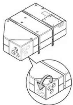
Decide whether the air outlet channels are to exit from the side or the front. Position the air outlets on the air conditioning unit accordingly.
Place installation template in stowage compartment and fix in position. Mark mounting holes for the 4 front, rear and side retaining brackets (2).
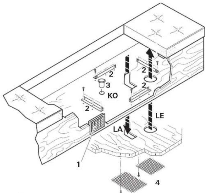
The legs of the side retaining brackets (2) should point outwards in order to make the unit easier to detach from the false floor (if necessary)!
Mark floor opening "LE" for the air supply, "LA" for the outgoing air and "KO" for the condensation drain.
Remove template and cut out the marked floor openings.
Before drilling, always check for underlying / concealed cables, gas lines, frame sections and the like!
Then seal the edges of the openings in the floor of the vehicle with underbody protection.
Screw down the 4 retaining brackets (2) using 3 screws per bracket.
Insert muff (3) for condensation drain (KO) from above.
Place air conditioning unit in stowage compartment (between the 4 retaining brackets).
When installing the unit, please ensure that the muff (3) of the condensation drain is located in the recess in the floor of the vehicle. Otherwise there is a risk of water penetrating the interior! In order to provide good air circulation, the openings in the bottom of the unit and the floor must align exactly. Correct operation of the unit cannot be guaranteed unless this is the case!
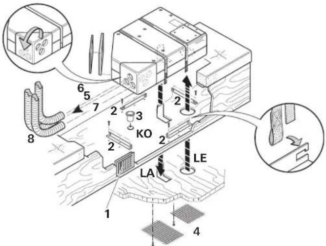
Hook the two clamping straps onto the 2 side retaining brackets (2) and route the clamping straps around the air conditioning unit as securely as possible and secure with the Velcro fastener.
The air conditioning unit must be attached at all sides using the brackets provided in order to prevent unintentional movement if vigorous movements occur (e.g. hard braking).
Seal muff (3) for condensation drain all round from below using body sealant.
Attach the two floor grilles (4) for LE and LA to the floor of the vehicle from below with suitable screws or clips (not provided).
Cold air distribution and circulating air return feed
Cold air distribution
A KR 65 65 mm (8) cold air duct with at least one outlet must be connected to each of the three cold air emitters of the unit (5, 6 and 7).
Slide the cold air ducts (8) into the cold air emitters of the unit and route to the air outlet nozzles. Truma can supply a sound muffler for installing in the cold air system (part no. 40040-60100) as an accessory for reducing the noise level.
The RL rectangular air outlets (part no. 40280-01) with the ANH connecting piece (part no. 40920-02) are particularly suitable for use as cooled air outlets into the vehicle interior.
The cold air distribution system is individually designed for each vehicle model using a modular principle. A wide range of accessories is available for this purpose.
In order to achieve the best possible cooling power, we recommend:
- Route cold air pipes to air vents as short and straight as possible.
- The total accumulated length of cold air duct that may be used is 15m .
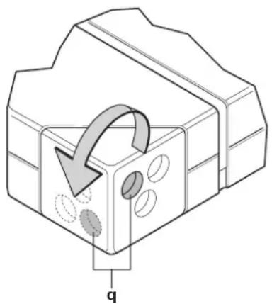
- Connect the longest cold air duct (max. 8 m) to the marked cold air outlet (q), since this has the most air throughput.
- To prevent condensation, do not route cold air ducts in the vicinity of incoming outside air (or behind the refrigerator).
Circulating air return
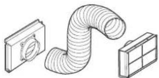
The circulating air is drawn in again by the unit, either through an additional rectangular air grille (1 - part no. 40040-29200) or 3 round air grilles (part no. 40040-20400), e.g. in the stowage box wall or via several smaller openings with a total area of at least 300~cm^2
Important note
To ensure trouble-free air exchange, the air infeed from the interior of the vehicle to the installation location must be located in the immediate vicinity of the device. If appropriate, covers are to be fitted, in order to avoid the circulating air return being impeded by stowed objects.

If the equipment cannot be installed in close proximity, Truma can provide a flexible air intake (part no. 40090-00) as an accessory.
Installing the infra-red receiver
The receiver (9) is to be fitted for preference on the clothes cabinet in such a way that the remote control can be pointed at it without any hindrance (length of connection cable 3m ). If necessary, a 3 metre cable extension can be supplied (part no. 40090-89100).

If the receiver cannot be flush-mounted, Truma can provide an on-surface frame (10 - part no. 40000-52600) in accessory if required.
Drill a hole 55mm in diameter. Lead the cable through from behind and secure the receiver with 4 screws (11). Then attach the cover frame (12), route the cable to the air conditioning unit and connect to the unit at the side.
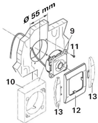

Truma offers side parts (13) in eight different colors for finishing the cover frames (12) in a visually pleasing way. See ask your dealer.
230 V electrical connection and IR receiver connection
The electrical connection must always be made by an expert (in accordance with VDE 0100, part 721 or IEC 60364-7-721 in Germany)! The instructions given here are not a challenge to the lay person to carry out the electrical connection, but serve to provide additional information for the professional fitter whom you engage!
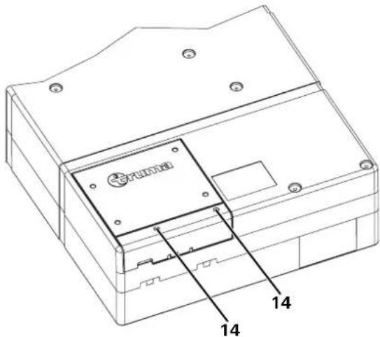
Unscrew 2 screws (14) and open the cover of the electronic system.
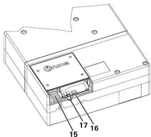
Insert mains cable plug (15) into socket. The plug is automatically provided with strain relief by engaging in a retaining lug. The retaining lug must be lifted with a screwdriver in order to remove the plug from the socket.
Insert IR receiver plug into socket (16).
The connection (17) is needed if the Saphir vario air conditioning unit is being operated via a Truma TG 1000 sinus power inverter (COM connection / communication a or b).
Close electronic system cover again and screw the screws (14) back in.
The cables must be long enough for the unit to be pulled out of the false floor with the cables attached. All cables must be secured with cable clips!
For maintenance or repair work, an isolating device must be provided on the vehicle side to provide all-pole isolation from the mains, with a contact interval of at least 3.5mm
Function test / Mounting for the remote control
Position the mounting for the remote control as close as possible to the receiver (9), in order to allow for the air-conditioning system to be operated without removing the remote control from its mounting.
In conclusion, all the functions of the device need to be tested in accordance with the Operating Instructions.
The operating instructions must be handed to the owner of the vehicle.
Table des matieres
600 W = LED 1 (COOL LOW),
1500 W = LED 2 (COOL),
2000 W = LED 1 + LED 2 (COOL HIGH)
LED 1 e LED 2 (2000 W)
600 W = LED 1 (COOL LOW),
1500 W = LED 2 (COOL),
2000 W = LED 1 + LED 2 (COOL HIGH)
FAN = Kun ventilation
COOL = Køling og
ventilation
b = FAN
Ventilatoreffekt
LOW = Lav
HIGH = H0j
c = TEMP.
600 W = LED 1 (COOL LOW),
1500 W = LED 2 (COOL),
2000 W = LED 1 + LED 2 (COOL HIGH)
Para lograr un funcionaperfecto y evitar daños soloSEOSEOSEOSEOSEOSEOSEOSEOSEOSEOSEOSEOSEOSEOSEOSEOSEOSEOSEOSEOSEOSEOSEOSEOSEOSEOSEOSEOSEOSEOSEOSEOSEOSEOSEOSEOSEOSEOSEOSEOSEOSEOSEOSEOSEOSEOSEOSEOSEOSEOSEOSEOSEOSEOSEOSEOSEOSEOSEOSEOSEOSEOSEOSEOSEOSEOSEOSEOSEOSEOSEOSEOSEOSEOSEOSEOSEOSEOSEOSEOSEOSEOSEOSEOSEOSEOSEOSEOSEOSEOSEOSEOSEOSEOSEOSEOSEOSEOSEOSEO SEOEO SEOEO SEOEO SEOEO SEOEO SEOEO SEOEO SEOEO SEOEO SEOEO SEOEO SEOEO SEOEO SEOEO SEOEO SEOEO SEOEO SEOEO SEOEO SEOEO SEOEO SEOEO SEOEO SEOEO SEOEO SEOEO SEOEO SEOEO SEOEO SEOEO SEOEO SEOEO SEOEO SEOEO SEOEO SEOEO SEOEO SEOEO SEOEO SEOEO SEOEO SEOEO SEOEO SEOEO SEOEO SEOEO SEOEO SEOEO SEOEO SEOEO SEOEQ
600 W = LED 1 (COOL LOW),
1500 W = LED 2 (COOL),
2000 W = LED 1 + LED 2 (COOL HIGH)
GB Always notify the Truma Service Centre or one of our authorised service partners if problems are encountered (see Truma Service book or www.truma.com).
Having the equipment model and the serial number ready (see type plate) will speed up processing.
- Operating instructions
- Installation instructions
- Symbols used
- Safety instructions
- Notes for the use of air-conditioners
- Remote control
- Taking into operation
- Switching off
- Timer off
- IR receiver and manual on / off
- Operating indicator
- Red LED illuminates
- Maintenance
- Trouble-shooting
- Changing the battery in the remote control
- Disposal
- Accessories
- Operating modes of the TG 1000 sinus power inverter with the Saphir vario air conditioning unit
- Operating mode 1
- via auxiliary battery with 12V
- Regardless of the mode that is selected, the cooling power is limited to the lowest setting in this mode (COOL LOW), even if a higher cooling mode is indicated!
- Operating mode 2
- via alternator with 12 V
- Regardless of the mode that is selected and indicated, the cooling power is limited to the lowest and medium setting in this mode (COOL LOW or COOL), even if a higher cooling mode is indicated!
- Tip
- Operating mode 3
- via national network with 230V
- Technical data
- Designation
- Area of operation
- Dimensions (L x W x H)
- Weight
- Maximum cooling capacity
- Start-up current
- Power consumption
- Protection mode
- Volume flow (cold air)
- Cooling agent
- Cooling agent content
- Maximum inclination of vehicle during operation
- Operational limits
- EEC type approval
- Installation dimensions
- Manufacturer's terms of warranty
- Case of warranty
- Scope of warranty
- Raising the case of warranty
- Intended use
- Approval
- Declaration of conformity
- Provisions
- Location selection
- Installing the air conditioning unit
- Before drilling, always check for underlying / concealed cables, gas lines, frame sections and the like!
- Cold air distribution and circulating air return feed
- Cold air distribution
- Circulating air return
- Important note
- Installing the infra-red receiver
- V electrical connection and IR receiver connection
- Function test / Mounting for the remote control
- Table des matieres
Brand : TRUMA
Model : Saphir Vario
Category : Air Conditioning