
AVS77 - Home theater audio system YAMAHA - Free user manual and instructions
Find the device manual for free AVS77 YAMAHA in PDF.
| Product Type | 5.1-channel home theater audio system |
| Brand | YAMAHA |
| Model | AVS77 |
| Maximum output power (front) | 25 W + 25 W (1 kHz, 10% THD, 6 Ω) |
| Maximum output power (rear) | 25 W + 25 W (1 kHz, 10% THD, 6 Ω) |
| Maximum output power (subwoofer) | 50 W (100 Hz, 10% THD, 5 Ω) |
| Signal-to-noise ratio | 95 dB (AUX, IHF-A) |
| Total harmonic distortion | 0.05% (AUX, 1 kHz, 12.5 W/6 Ω) |
| Front speakers - type | Bass-reflex, magnetic shielding |
| Front speakers - drivers | 2 x 8 cm cone |
| Front speakers - impedance | 6 Ω |
| Front speakers - frequency response | 120 Hz - 20 kHz |
| Front speakers - dimensions (W x H x D) | 600 x 110 x 220 mm |
| Front speakers - weight | 5.0 kg |
| Rear speakers - type | Acoustic suspension, magnetic shielding |
| Rear speakers - driver | 8 cm cone |
| Rear speakers - impedance | 6 Ω |
| Rear speakers - frequency response | 140 Hz - 20 kHz |
| Rear speakers - dimensions (W x H x D) | 100 x 140 x 112 mm |
| Rear speakers - weight | 0.8 kg |
| Subwoofer - type | YAMAHA advanced active servo technology, magnetic shielding |
| Subwoofer - driver | 16 cm cone |
| Subwoofer - frequency response | 30 - 200 Hz |
| Power consumption in standby mode | 1 W |
| Audio inputs | TV (RCA), VIDEO (RCA), AUX (RCA), 2 x optical (DIGITAL 1, DIGITAL 2) |
| Outputs | Headphone jack (PHONES on subwoofer) |
| Built-in decoders | Dolby Digital, Dolby Pro Logic, DTS |
| DSP programs | Virtual Surround, Dolby Digital, DTS, Digital Movie Theater, 70mm Movie Theater, DTS Movie Theater, Game, Hall, Concert/Sports, Mono Movie, Silent Cinema |
| Special functions | Bass enhancement (B. Boost), Night mode, Sleep timer, Settings memory (3), Multifunction remote control |
| Supplied accessories | Remote control, batteries, speaker cable, system connection cables, RCA audio cable, front speaker brackets, wall mounts |
Frequently Asked Questions - AVS77 YAMAHA
User questions about AVS77 YAMAHA
0 question about this device. Answer the ones you know or ask your own.
Ask a new question about this device
Download the instructions for your Home theater audio system in PDF format for free! Find your manual AVS77 - YAMAHA and take your electronic device back in hand. On this page are published all the documents necessary for the use of your device. AVS77 by YAMAHA.
USER MANUAL AVS77 YAMAHA
Home Theater Sound System System audio home cinema

Advanced
Y·S·T
OWNER'S MANUAL
MODE D'EMPLOI
- To assure the finest performance, please read this manual carefully. Keep it in a safe place for future reference.
- Install this unit in a cool, dry, clean place — away from windows, heat sources, sources of excessive vibration, dust, moisture and cold. Avoid sources of humming (transformers, motors). To prevent fire or electrical shock, do not expose the unit to rain or water.
- Never open the cabinet. If something drops into the unit, contact your dealer.
- Do not use force on switches, controls or connection cables. When moving the unit, first set the power of the front speaker unit to standby mode, disconnect the power cord of the subwoofer and then the cables. Never pull the cables themselves.
- Digital signals generated by this unit may interfere with other component such as tuners, receivers and TVs. Move this unit farther away from such component if interference is observed.
- Do not attempt to clean the unit with chemical solvents; this might damage the finish. Use a clean, dry cloth.
- Be sure to read the "TROUBLESHOOTING" section regarding common operating errors before concluding that the unit is faulty.
- When not planning to use this unit for a long period of time (e.g., a vacation), disconnect the AC power cord of the subwoofer from the wall outlet.
- To prevent lightning damage, disconnect the AC power cord of the subwoofer when there is an electrical storm.
- Though the unit is a magnetic shielding type, there may be some influence on a TV picture depending on the type of TV or the placement of the unit. In such a case, place the unit apart from the TV so that there is no influence on TV picture.
- To prevent the enclosure from warping or discoloring, do not place the unit where they will be exposed to direct sunlight or excessive humidity.
- Do not place the following objects on top of the unit:
- Other components, as they might cause damage and/or discoloration on the surface of the unit.
- Burning objects (i.e. candles), as they might cause fire, damage to the unit and/or personal injury.
- Containers with liquid in them, as they might cause electric shock to the user and/or damage to the unit.
- Do not place the unit where it is are liable to be knocked over or struck by falling objects. Stable placement will also ensure better sound performance.
- Secure placement or installation is the owner's responsibility. YAMAHA shall not be liable for any accident caused by improper placement or installation of the unit.
- Do not attempt to modify or fix the unit. Contact qualified YAMAHA service personnel when any service is needed. The cabinet should never be opened for any reasons.
For the front speaker unit
- Always set the volume to the minimum level before starting the audio source play. Increase the volume gradually to an appropriate level after playback has been started.
For the subwoofer
- The voltage used must be the same as that specified on the rear panel. Using this unit with a higher voltage than specified is dangerous and may result in fire or other accidents. YAMAHA will not be held responsible for any damage resulting from the use of this unit with a voltage other than that specified.
- For heat release, be sure to allow a space of at least 10 cm above, behind and on both sides of the unit.
- Do not cover the rear panel of this unit with a newspaper, a tablecloth, a curtain, etc. in order not to obstruct heat radiation. If the temperature inside this unit rises, it may cause fire, damage to this unit and/or personal injury.
- Do not plug in this unit to a wall outlet until all connections are completed.
- Super-bass frequencies reproduced by this unit may cause a turntable to generate a howling sound. In such a case, move this unit away from the turntable.
- Vibration generated by super-bass frequencies may distort images on a TV. In such a case, move this unit away from the TV set.
- When disconnecting the power cord from the wall outlet, grasp the plug; do not pull the cord.
This unit is not disconnected from the AC power source as long as it is connected to the wall outlet, even if this unit itself is turned off. This state is called the standby mode. In this state, this unit is designed to consume a very small quantity of power.
■For U.K. customers
If the socket outlets in the home are not suitable for the plug supplied with this appliance, it should be cut off and an appropriate 3 pin plug fitted. For details, refer to the instructions described below.
Note
- The plug severed from the mains lead must be destroyed, as a plug with bared flexible cord is hazardous if engaged in a live socket outlet.
Special Instructions for U.K. Model
IMPORTANT
THE WIRES IN MAINS LEAD ARE COLOURED IN ACCORDANCE WITH THE FOLLOWING CODE:
Blue: NEUTRAL
Brown: LIVE
As the colours of the wires in the mains lead of this apparatus may not correspond with the coloured markings identifying the terminals in your plug, proceed as follows:
The wire which is coloured BLUE must be connected to the terminal which is marked with the letter N or coloured
BLACK. The wire which is coloured BROWN must be connected to the terminal which is marked with the letter L or coloured RED.
Making sure that neither core is connected to the earth terminal of the three pin plug.
FEATURES
The AV-S77 is the Home Theater Sound System that delivers a powerful and realistic sound experience like that found in a movie theater just by combining the front speaker unit with the TV.
The newest DSP programs will enhance the power and realism of various sources, from movies to concerts, and sporting events. Also, the Silent Cinema program allows you to enjoy the sound field even through the headphones.
Since the AV-S77 consists of a front speaker unit, rear speakers and subwoofer, you can enjoy stronger bass and surround effects as well as a good balance throughout the speakers. Moreover, the One-touch connection of the speaker cable designed exclusively for this unit allows you to easily connect the speakers.
Dolby Digital decoder
Dolby Pro Logic decoder
DTS (Digital Theater Systems) decoder
CINEMA DSP
Silent Cinema
Virtual Surround
- Easy connection of the front speaker unit, rear speakers and subwoofer using only one speaker cable designed exclusively for this unit
Slim and powerful subwoofer
Multi-function remote control which can also be used for other audio/video components of certain manufacturers

Manufactured under license from Dolby Laboratories.
"Dolby", "Pro Logic" and the double-D symbol are trademarks of Dolby Laboratories.

"DTS" and "DTS Digital Surround" are registered trademarks of Digital Theater Systems, Inc.
CONTENTS
PREPARATION
FEATURES 1
GETTING STARTED 2
NAMES OF ALL PARTS 4
SPEAKER PLACEMENT 6
INSTALLATION 7
CONNECTIONS 11
ADJUSTING THE SPEAKER OUTPUT LEVELS 20
OPERATION
OPERATING THE UNIT 22
USING CONVENIENT FUNCTIONS 24
DSP PROGRAM (DIGITAL SOUND FIELD
PROCESSING PROGRAM) 26
MENUFUNCTIONS 28
REMOTE CONTROL
indicates a tip for your operation.
GETTING STARTED
Checking the Package Contents
Check that the following accessories are included in the package.
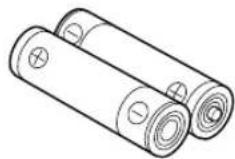
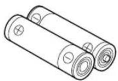
Batteries (x 2) (AA, R06, UM-3 type)Remote control
the front speaker unit
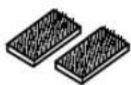
Connection guideFasteners (2 sets) for
Audio connection cord (2-pin, 3m x 1)

Speaker cable (x 1) (for the rear speakers: 15m for the front speaker unit:3m

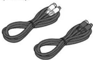
System connector cables (3m x 2)
Parts for the rear speakers installation
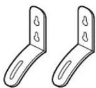
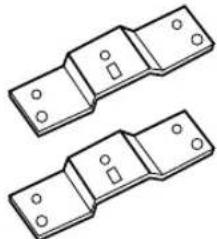
Type A brackets (x 2) Type B brackets (x 2) Screws (x 2)

Wing nuts (x 2)

Readying the Remote Control
Inserting the batteries
1 Remove the battery compartment cover.
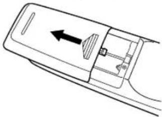
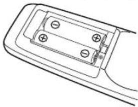
2 Insert the two batteries (AA, R06, UM-3 type) with + and - oriented properly.
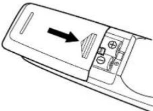
3 Close the battery compartment cover.
Precautions regarding batteries
Misuse of batteries may result in leakage or bursting. Be sure to follow the precautions given below.
- Insert batteries with (+) and (-) oriented according to the marking in the battery compartment.
- Do not mix old and new batteries.
- Do not mix different types of batteries as they may offer different voltage and performance even though they have the same shape.
- Remove all batteries if they can no longer be used or if the remote control is not going to be used for an extended period.
- Do not use rechargeable batteries.
- If leakage occurs, wipe away all battery fluid inside the compartment.
Preserving the manufacturer code
Replace batteries early before they become unusable. The manufacturer code set by the user will be preserved for about two minutes when batteries run out or when they are removed. Note that the manufacturer code setting may be lost if more than two minutes elapses. Also, if you press any button on the remote control accidentally while replacing batteries, the manufacturer code will be lost.
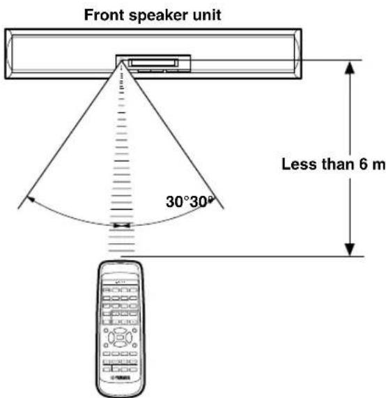
Operational Area of the Remote Control
■Battery replacement cycle
Replace all two batteries when the operational range of the remote control starts to become shorter.
Precautions on handling the remote control
- The remote control may not be able to operate the front speaker unit when an object blocks the remote control sensor on the unit.
- Do not subject the remote control to impact. Do not allow it to get wet or place it in a location subject to high humidity.
- The remote control operations become difficult when direct sunlight or other strong light (such as from an inverter fluorescent lamp) strikes the sensor. Adjust the relative positions of the light and the front speaker unit if this happens.
- Remote control operations may not be possible if another remote control is being operated at the same time.
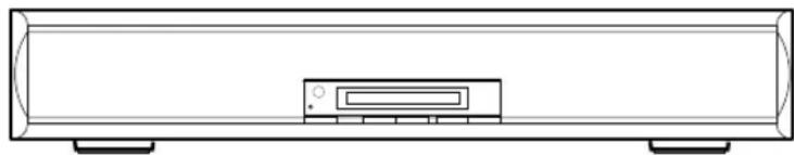
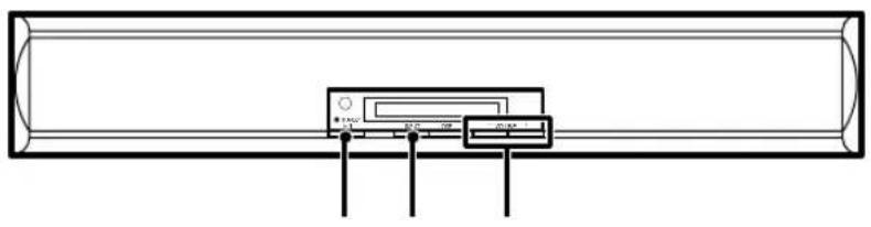
NAMES OF ALL PARTS
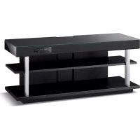
Front Speaker Unit (Front Panel)
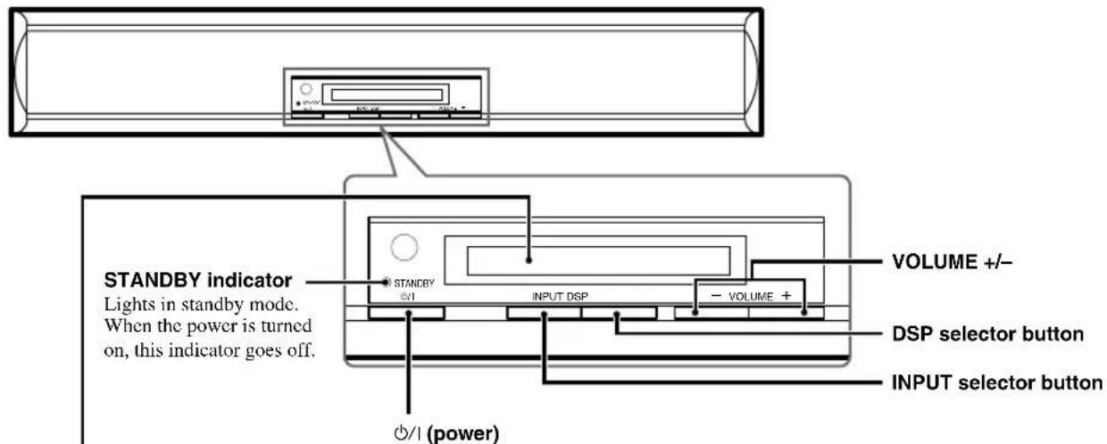
Turns the unit's power on and standby. When the power switch is set to standby mode, the STANDBY indicator is lit. When the power switch is turned on, the STANDBY indicator goes off.
When disconnecting and connecting the power supply cord of the subwoofer, or when restoring from a power failure, the unit returns to the last power status (standby or power on).
Display
The display becomes brighter for a few seconds each time this unit is operated, even after you have adjusted the brightness of the display to be dim, so that you can check the current operation clearly.
Processing indicators
Lights when the decoder or digital sound field processor is functioning.
VIRTUAL indicator
Lights when VIRTUAL SURROUND is selected.
Phones indicator
Lights when the headphones are connected.
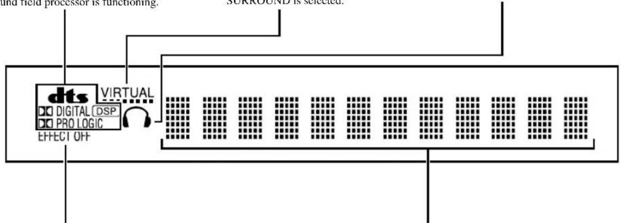
EFFECT OFF indicator
Lights when the sound field effects is not turned on.
Shows the various information such as an input source name, DSP program name, level or operational status
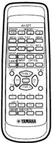
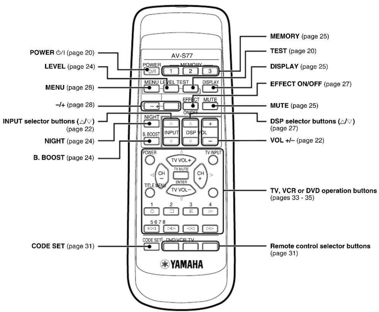
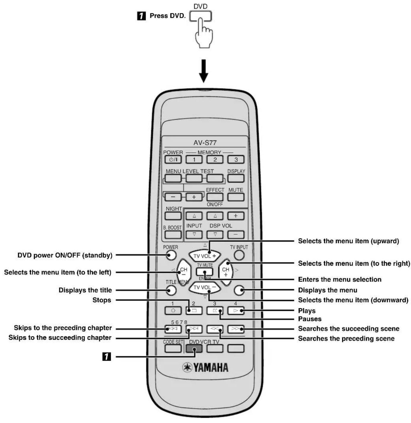
Remote Control
SPEAKER PLACEMENT
Although speakers should ideally be placed as shown below, try to adjust the speaker location according to the environment of your listening room so that you can experience the best sound field effect.
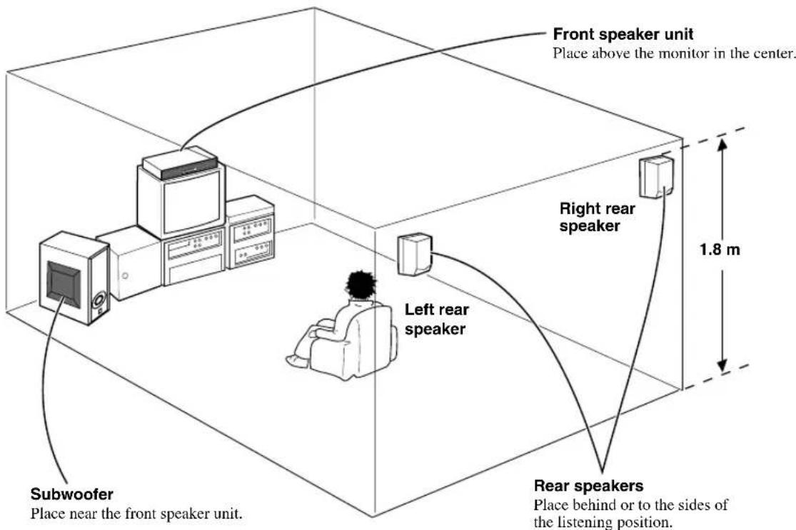
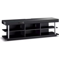
■Front speaker unit
Place the front speaker unit on top of the television and align the front surface of the speakers with the front surface of the television monitor. If the unit cannot be placed on top of the television, place it on a rack beneath the television as close to the television monitor as possible.
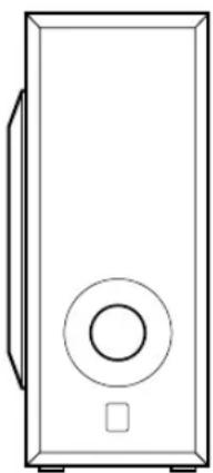
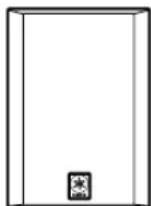
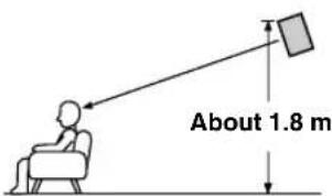
Rear speakers
Depending on room conditions, you can place rear speakers on shelves or hang them on the wall. Speakers should be placed about 1.8m above the floor.
Subwoofer
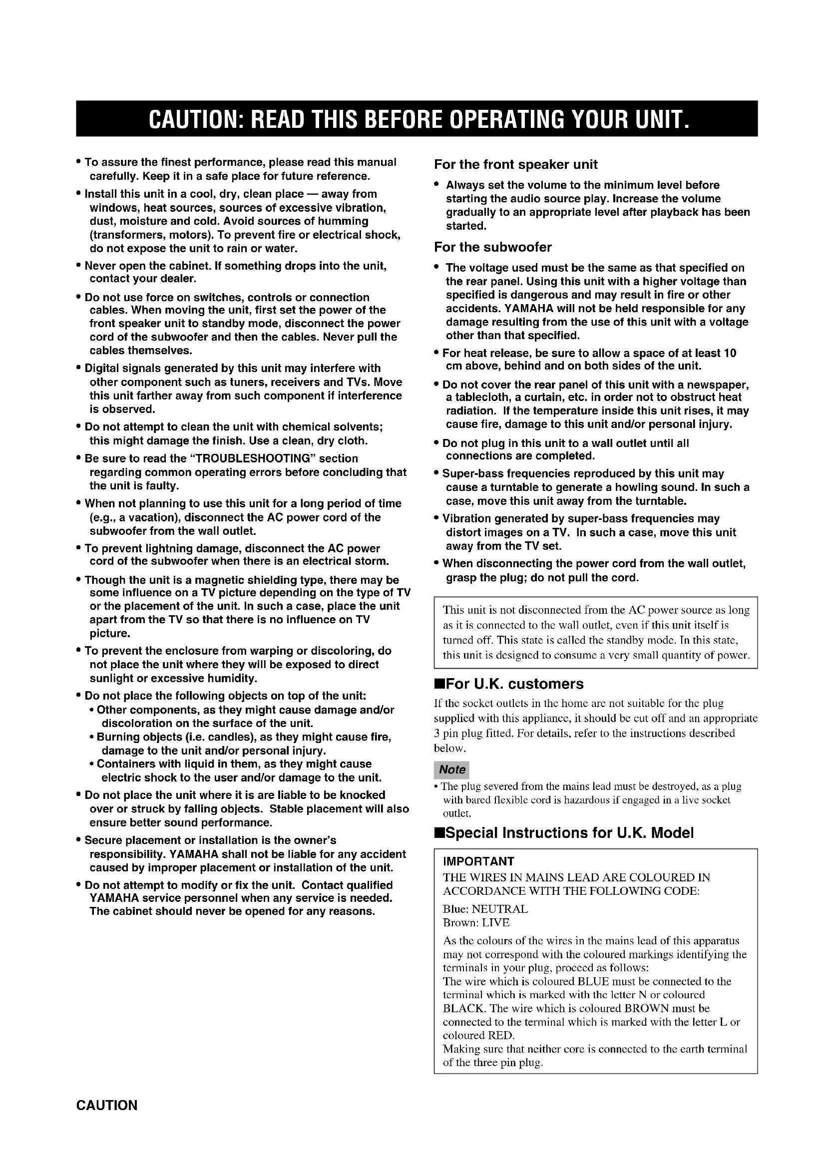
Place the subwoofer either at the right or left side of the front speaker unit and facing slightly toward the center of the room so that the sound from it and the sound reflected by the wall would not cancel each other out. As a transducer
is located on the left side panel of the subwoofer unit, place the subwoofer unit more than 10cm away from a wall or curtain. Try altering the position of the subwoofer versus the listening position as the relative position will affect the way the bass sounds.
CAUTION
- Although the speaker system in this unit is magnetically shielded, it may still affect the color on the television monitor when using this unit near the television. Adjust the relative positions of this unit and the television if this happen. Perform the following steps if you are using a television with a demagnetizing function.
1 Turn off the television.
2 Wait awhile and turn the television back on.
- Install the speaker system in a well-ventilated place.
- Since there is a low frequency sound output from the opening and transducer of the subwoofer, do not place an object near these areas of the subwoofer.
- When transporting the subwoofer, do not put your hand on the left side of the subwoofer. Doing so may damage the speaker or grille panel.
INSTALLATION
Installing the Front Speaker Unit
To prevent the front speaker unit from falling, secure it with the provided fastener when placing it on a television or other device. Also, use the height adjustment bracket on the rear of the front speaker unit when there is a step on the installation surface.
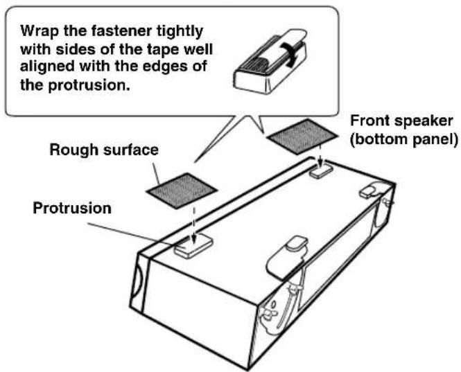
Using the fasteners
Precautions before installation
- Do not touch the adhesive surface after peeling off the strip as this will weaken its adhesive strength.
- Thoroughly wipe clean the surface where the fastener is to be applied. Note that adhesive strength is weakened if the surface is dusty, oily or wet and that this may cause the front speaker unit to fall.
Peel off the seal of the fastener with the rough surface and apply to the protrusions on the bottom of the front speaker unit.
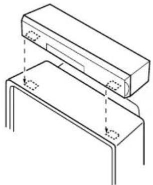
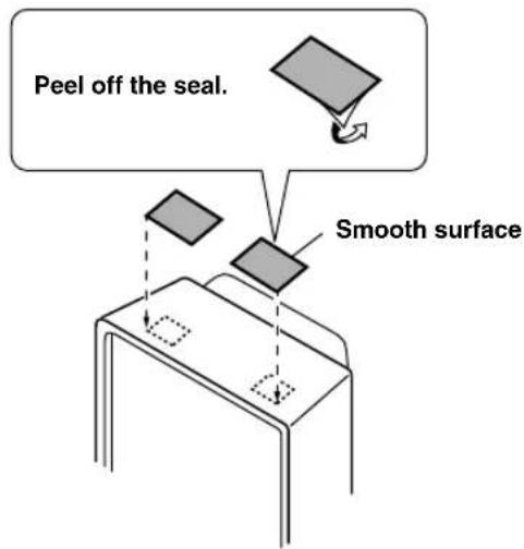
2 Place the front speaker unit where it is to be installed (ex. on top of the television) to determine where to apply the fastener with the smooth surface.
Position it so that the fastener stuck to the front speaker unit matches that of the fastener stuck to the top of the television.
3 Peel off the seal of the fastener with the smooth surface and apply to the positions determined in step 2.
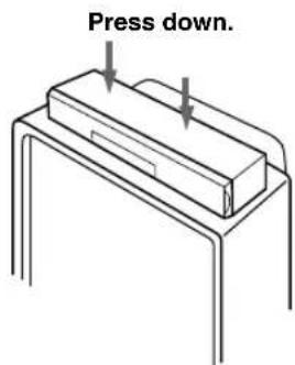
4 Align the fasteners on both sides and firmly press downward from the top of the front speaker unit.
Note
- Once the front speaker unit is secured in this way, the paint on the television surface used for installation may peel off when fastener is removed later. Be sure to apply fasteners after carefully checking the surface you are going to use for installation.
INSTALLATION
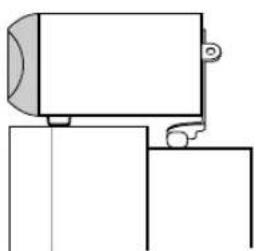
Using the height adjustment brackets
Precautions before installation
- Do not install the unit on a tilted surface, or in a place where there is not enough even space.
- Do not install the unit on a surface where the unit cannot be placed horizontally even with the use of the adjustment bracket.
1 Loosen the screws securing the adjustment bracket.
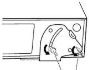
Loosen the screws.
2 Lower the bracket so that the front speaker unit is level and securely tighten the screws.
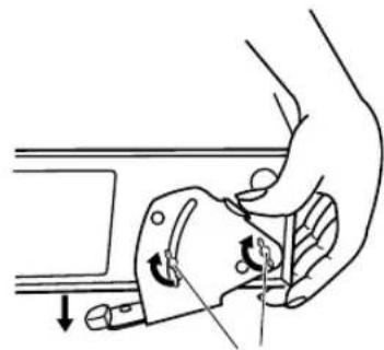
Lower the bracket and adjust.
Securely tighten the screws.
Place the front speaker unit so that it is level.
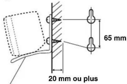
To further stabilize and prevent falling
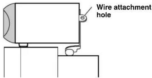
Secure the front speaker unit to the wall by attaching sufficiently strong wire to the wire attachment hole on the adjustment bracket. This will double the safety measure when used together with fasteners to prevent damage caused by the front speaker unit falling.
Note
- Please provide wire separately.
CAUTION
Never place anything on top of the front speaker unit.
Installing the Rear Speakers
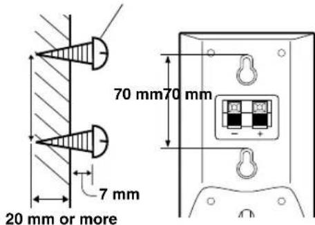
To mount the rear speakers on a wall using the provided mounting brackets (type A)
Use the provided mounting brackets (type A) when hanging the rear speakers on a wall.
- When hanging the rear speakers on a wall, be sure to connect the speaker cable to the rear speakers beforehand. It is difficult to connect the rear speaker cable after hanging. For details of the speaker cable connection, refer to page 18.
1 Attach two commercially available protruding screws (diameter about 4mm ) in the location on the wall where the rear speaker is to be hung, and then mount the bracket on the protruding screws.
Check that the screws are secure inside the narrow portion of the holes in the bracket.
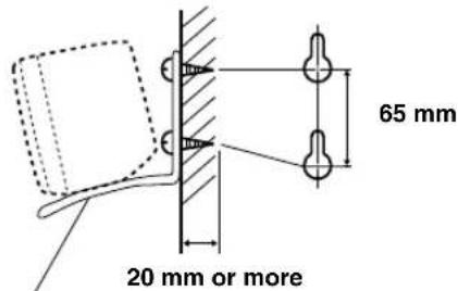
Mounting bracket (type A) (provided)
2 Attach the speaker to the bracket using the provided wing nut.
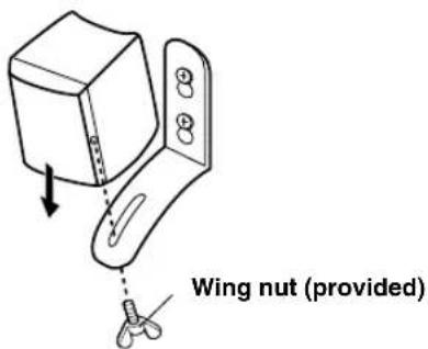
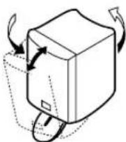
3 Adjust the angle of the speaker and then tighten the wing nut.
■To mount speakers directly to the wall
It is possible to hang the speakers directly on the wall without using the mounting brackets by attaching two protruding screws to the wall and then using the holes on the rear panel of the speakers for direct attachment.
Protruding screws of about 4 to 5mm in diameter (commercially available)
Note
After mounting, check that the speakers are attached securely.
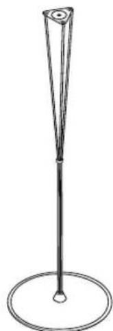
YAMAHA speaker stand SPS-AV1 (sold separately)
The rear speakers can also be attached to SPS-AV1 speaker stands and used as floor stand speakers.
To mount the rear speakers on the commercially available speaker stands
The provided mounting brackets (type B) with 1 pair of screw holes (at an interval of 60~mm ) can be used to mount the rear speakers on the commercially available speaker stands.
- Also refer to the instructions manual for the speaker stands.
1 Attach the mounting bracket (type B) to the bottom of the speaker using the provided screw.
Align so that the protrusion on the bracket goes into the groove on the bottom of the speaker.
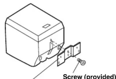
Mounting bracket (type B) (provided)
2 Mount the speaker on the speaker stand using the bracket holes.
Be sure to prepare small screws (diameter: 4mm length: 8mm ), spring washers and washers.
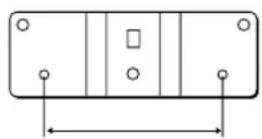
60 mm
CAUTION
Be sure to read these important precautions.
Each speaker weighs approximately 0.8kg . Select a firm wall or pillar to attach screws to. Do not attach screws to material such as mortar or veneer as screws may come loose easily, causing the speaker to fall.
- Do not mount speakers using nails or tape as vibrations during operation may cause nails to come loose or tape to peel off, causing the speaker to fall.
- Take care that the speaker cable is not pinched between the speaker and the bracket. Be sure that the speaker cable passes through the groove on the rear panel of the speaker.
- Secure the speaker cables so that they will not catch on hands or feet, causing speakers to fall.
- Be absolutely sure to check for safety after speakers are mounted. YAMAHA bears no responsibility for damage caused due to improper installation or installation in an improper location.
CONNECTIONS
CAUTION
Plug the power cord of the subwoofer into a wall outlet when all connections are complete.
To ensure proper connections
- Connect the white plug of the connection cord to the left "L" (white) audio signal terminal and connect the red plug to the right "R"(red) terminal.
- Insert the plug securely. If the plug is not inserted securely, noise may result or sound may not be output.
- Since the method of connection and terminal names differ depending on the component being used, be sure to refer to the instruction manuals for all components being connected.
After connections have been made, check one more time that wiring has been made properly.
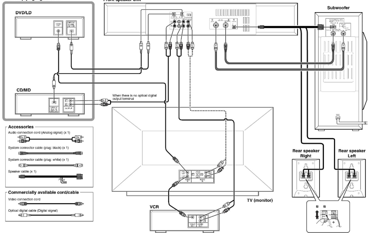
Connecting a TV or VCR
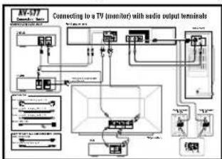
Connecting a TV (monitor) with audio output terminals
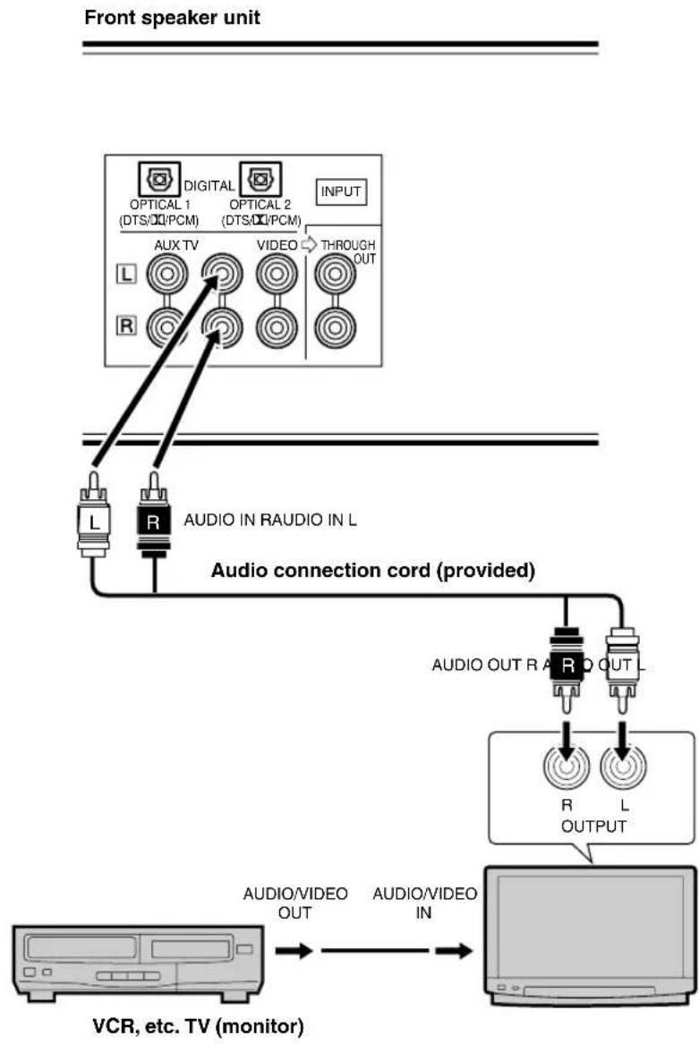
Connect the audio output terminal on the TV (monitor) to the TV terminal on the front speaker unit using the provided audio connection cord.

- Television audio can be heard from the AV-S77. (Although you can also hear the audio using the TV speakers, we recommend you reduce the TV volume so that you may enjoy the full benefit of the front speaker unit.)
Connecting to a TV (monitor) without audio output terminals
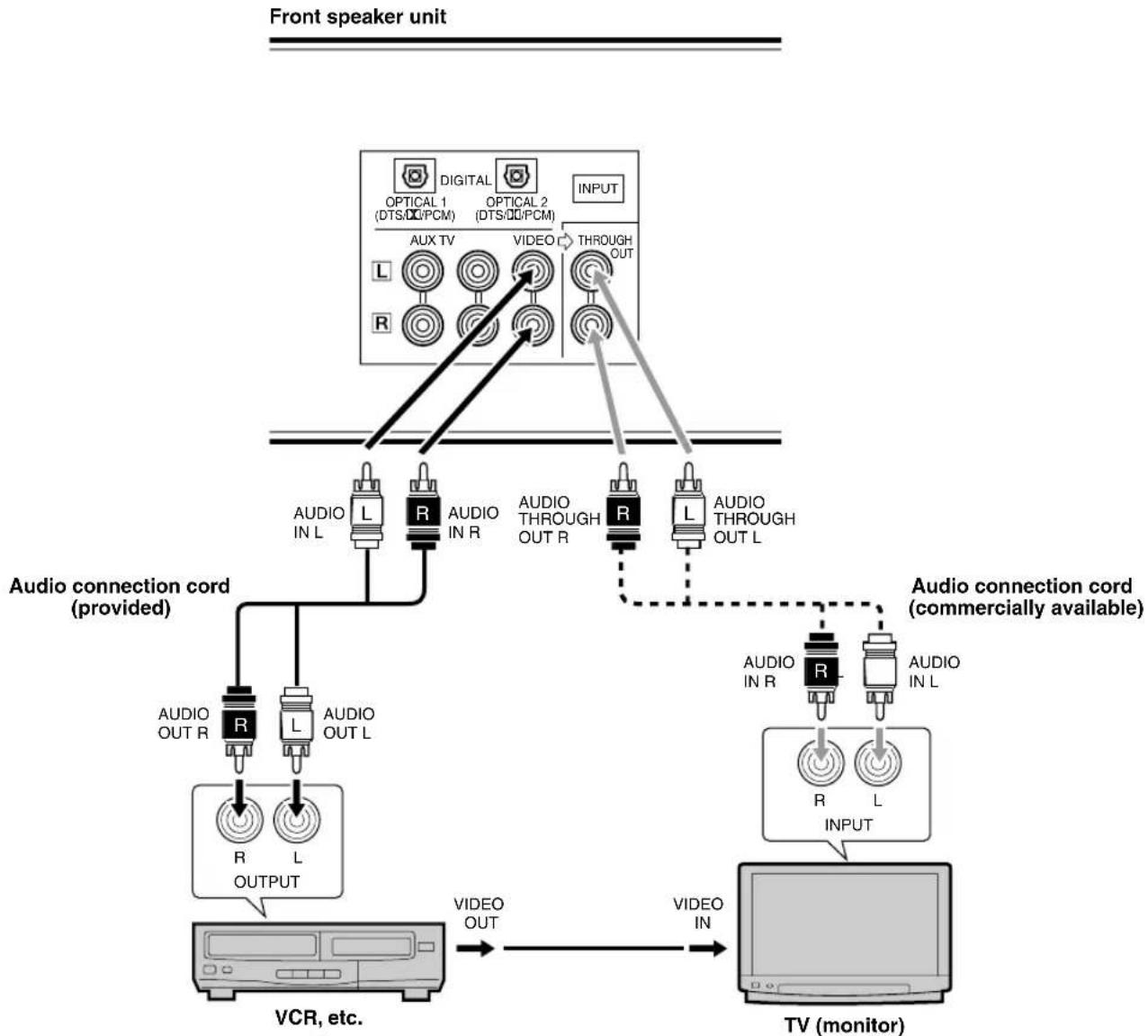
There are two methods of making connection:
1. connecting only the VIDEO terminals or
2. connecting the THROUGH OUT terminals in addition to the VIDEO terminals.
When only the VIDEO terminals are connected
Connect the audio output terminals on the VCR to the VIDEO terminals on the front speaker unit using the provided audio connection cord. VCR audio may always be heard from the AV-S77.
When VIDEO terminals and THROUGH OUT terminals are connected
Connect the THROUGH OUT terminals on the front speaker unit to the audio input terminals on the TV (monitor) using a commercially available audio connection cord. Audio can be heard from the TV speakers even when the front speaker unit is in standby mode.
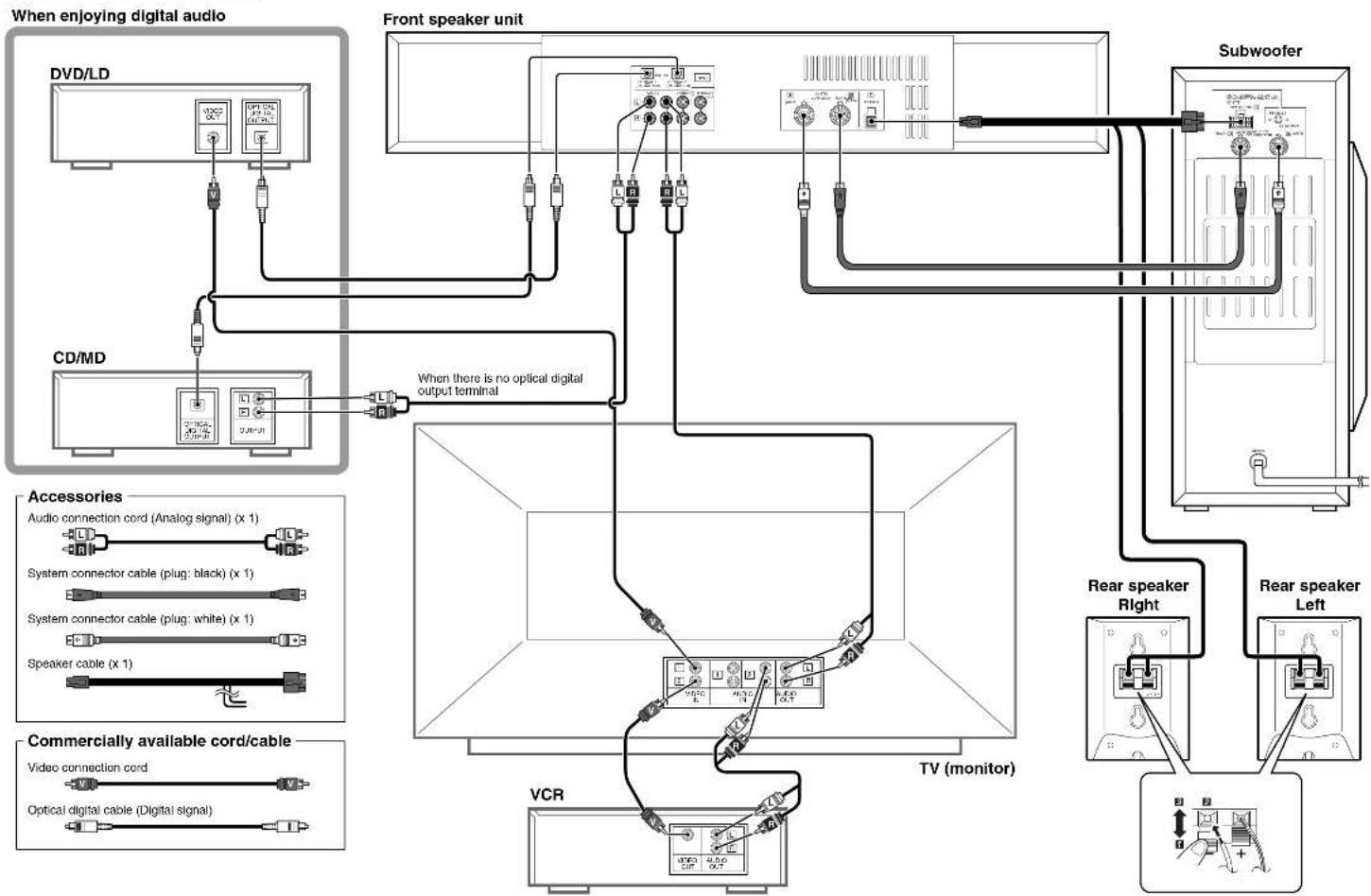
Connecting a DVD player, etc. to Enjoy Digital Audio
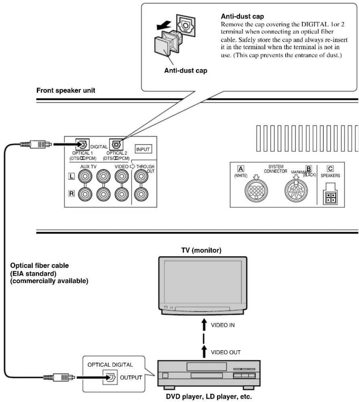
Connect the optical output terminal on the LD or DVD player to the DIGITAL 1 or 2 input terminal on the front speaker unit using a commercially available optical fiber cable.

The audio of the DVD or LD player can be heard from the AV-S77, but not from the TV speakers.
Connecting a CD Player or MD Recorder
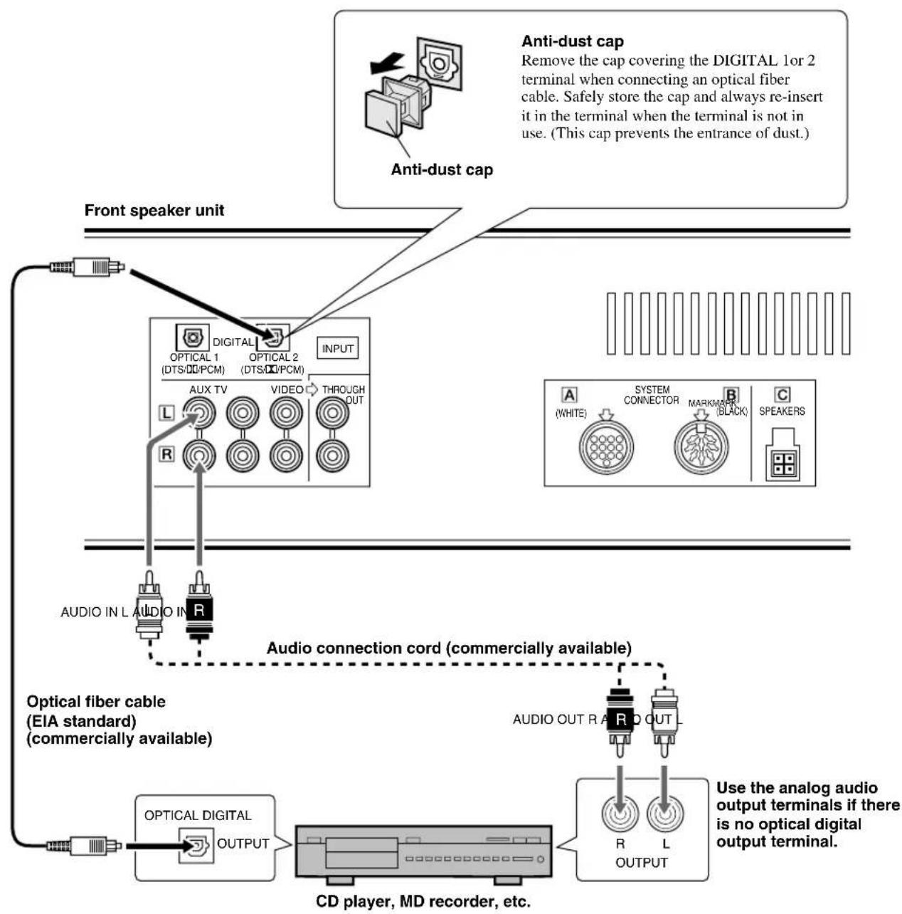
Connect the optical output terminal on the CD player or MD recorder to the DIGITAL 1 or 2 terminal on the front speaker unit using a commercially available optical fiber cable.
If there is no optical output terminal, connect the analog audio output terminals on the CD player or MD recorder to the AUX input terminals on the front speaker unit using a commercially available audio connection cord (2-pin).
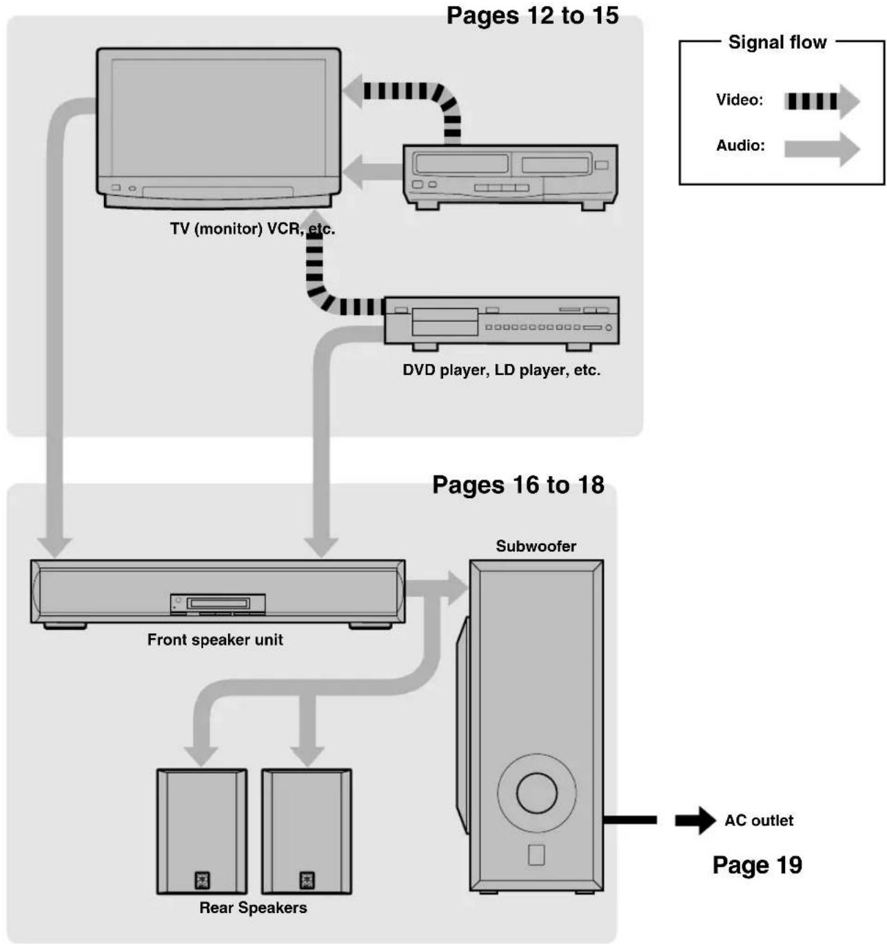
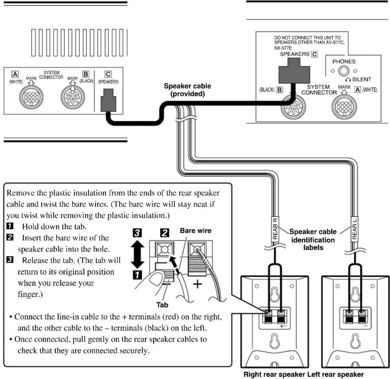
Connecting the Front Speaker Unit, Subwoofer and Rear Speakers
■Connection layout
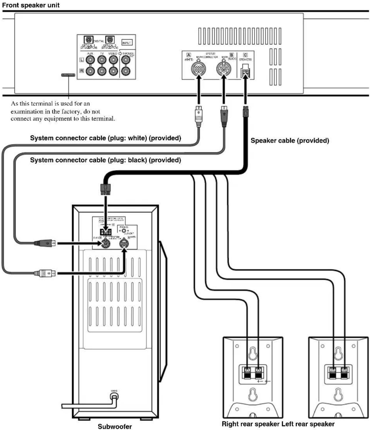
First, connect the front speaker unit and the subwoofer using the provided system connector cables and the speaker cable. Then, connect the rear speakers using the rear speaker cables that are branched from the speaker cable.
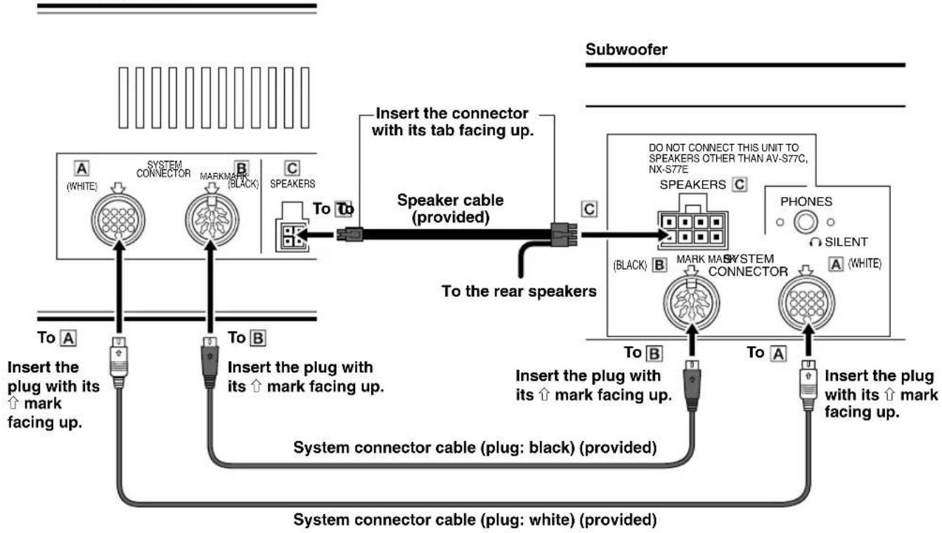
Connecting the front speaker unit and the subwoofer
Front speaker unit
Make sure that the plugs and connectors are positioned correctly before inserting them.
- Connect SYSTEM CONNECTOR A on the front speaker unit and the subwoofer using the provided system connector cable (plug: white).
- Connect SYSTEM CONNECTOR B on the front speaker unit and the subwoofer using the provided system connector cable (plug: black).
- Connect SYSTEM CONNECTOR on the front speaker unit and the subwoofer using the provided speaker cable.
To remove the connector of the speaker cable
Remove the connector while keeping the tab pressed down.
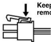
Keep pressing the tab and remove the connector.
Notes
- Do not insert the plug or connector forcibly. Doing so may damage the plug, connector or terminal.
- Do not scratch, forcibly bend, or pull the system connector or speaker cable as this may damage the cable, causing loss of audio output, and may possibly result in a fire or electric shock. Take particular care in making sure that the cable is not squashed by a rack or caster.
- Before disconnecting or connecting the system connector cable, set the front speaker unit to standby mode and then disconnect the power supply cord of the subwoofer.
Connecting the rear speakers
Front speaker unit
CAUTION
- Do not let the bare speaker wire touch each other and do not let them touch any metal part of the speakers. This could damage the speakers.
- Do not mistakenly connect plus (+) to minus (-) or vice versa when connecting the rear speaker cables.
- Insert the rear speaker cables securely so that plus (+) and minus (-) do not short. The speaker may not output any sound or may output noise, causing damage to the speakers, if speaker cables are not inserted securely.
- Insert only the bare wire portion of the speaker cables into the holes. Sound will not be output if you insert as far as the plastic insulation part of the cable.
- Secure the rear speaker cables so that they will not catch on hands or feet.
Connecting the AC Power Supply Cord
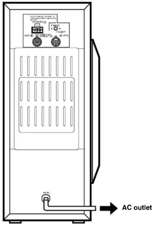
Subwoofer
Once all connections have been made, check them one more time. Finally, insert the plug of the power supply cord of the subwoofer into an AC outlet. Disconnect the power supply cord if you will not use the unit for an extended period.
Note
- When disconnecting the power supply cord, turn off the power of the front speaker unit beforehand.
Memory back-up
The memory back-up circuit prevents the following settings from being lost even when this unit is in the standby mode, the power supply cord is disconnected from the AC outlet, or the power supply is temporarily cut due to a power failure.
Volume level
- Input source
- Input name
- Dimmer
- Auto power off
Memory
Bass boost
Night mode
- Main display
DSP program selected with input source
- Effect on/off
- Channel level (left and right main channels, center channel, left and right rear channels and subwoofer) (When the silent cinema or virtual surround program is selected, the rear channel level is also stored.)
- Delay time
- Power status just before the power is cut off (standby mode or power on)
When reproducing the source encoded with a Dolby Digital, Dolby Surround or DTS using an appropriate DSP program, it is important to adjust the sound output level of each channel to be the same when heard at the listening position, so that the best performance of these digital sound fields can be obtained. Even when the other sound field is selected, you can enjoy the characteristics of each sound field.
Speaker output levels may be adjusted by using the remote control before playback by following the steps.
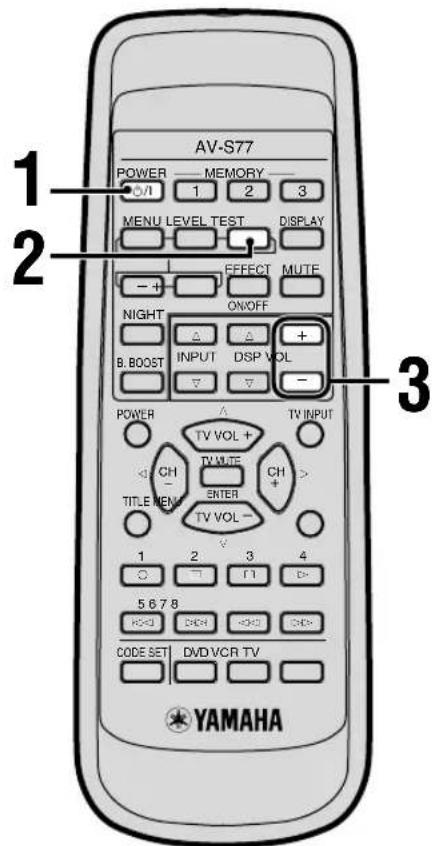
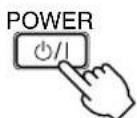
1 Press POWER / to turn on the power.
The STANDBY indicator goes off.
Press TEST.
Test tones (like pink noise) will be output in the following order.
A: When the VIRTUAL SURROUND or SILENT CINEMA program is selected

- You can hear the sound of the left and right main channels or rear virtual channels through the headphones when SILENT CINEMA is selected.
B: When the DSP program except the VIRTUAL SURROUND or SILENT CINEMA is selected
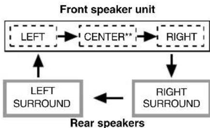
** Although the center speaker is not built into the front speaker unit, the sound of the center channel is output from the left and right main channels simultaneously.
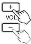
3 Adjust the level of the test tone using VOL + / - (Adjust to your listening level.)
Pressing VOL ^+ increases the level, while pressing VOL - decreases the level.
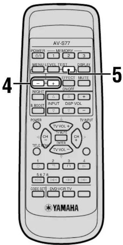
5 When the adjustment is complete, press TEST. A test tone will stop.


The sound output level can be adjusted in the following range.
-
When the VIRTUAL SURROUND or SILENT CINEMA is selected:
-
Right and left main channels (for VIRTUAL SURROUND only): -10 to ± 0 dB
Rear virtual channels: -3 to +3 dB
The minimum level for the main channels is -10dB while that for the rear virtual channels is -3dB . -
When the DSP program except for the VIRTUAL SURROUND or SILENT CINEMA is selected:
-Right and left main channels: -10 to ± 0 dB
- Center channel: -20 to +3 dB
-Right and left rear channels: -20 to +6dB
- The minimum level for the main channels is -10dB , while that for the center channel and the rear channels is -20dB .
4 Adjust the sound output level of each channel while listening to the test tone.
Pressing ^+ increases the level, while pressing - decreases the level.
In case of A
Adjust the sound output levels of the rear virtual channels and the main channels so that they become almost the same.
- The sound output level cannot be adjusted for each right or left rear virtual channel separately.
In case of B
Adjust the sound output levels of the center channel and the rear channels so that they become almost the same as that of the main channels.

- When the SILENT CINEMA is selected, a test tone is heard in the order of A. However, the sound output level of the main channels cannot be adjusted. Only the sound output level of the rear virtual channels can be adjusted.
- When you have adjusted the sound output levels of the main channels, readjust that of the center channel and rear channels, or the rear virtual channels.
OPERATING THE UNIT
Enjoying the Home Theater Sound System
This section describes how to select audio output from A/V component such as a TV, VCR, or DVD, LD, CD player, or MD recorder as input source to the Home Theater Sound System AV-S77 and how to adjust volume level.
First turn on the power of the playback component and the TV, and then follow the steps below.
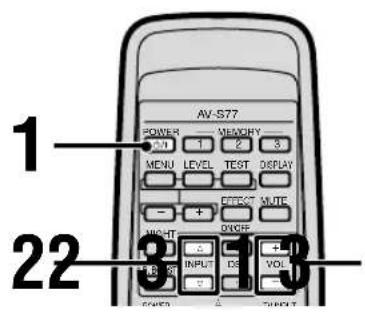
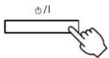
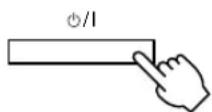
1 Press /1 (or POWER /1 on the remote control) to turn on the power.
or

Front panel
Remote control
The STANDBY indicator goes off.
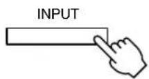
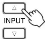
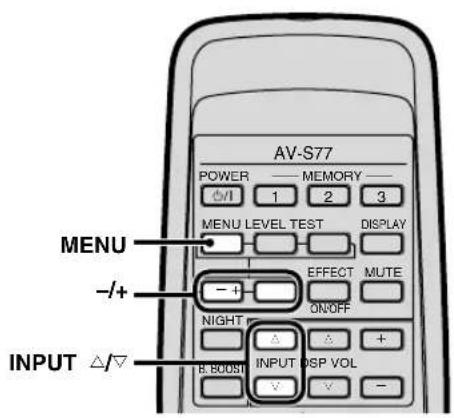
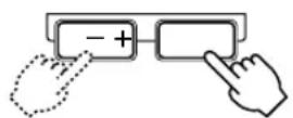
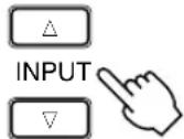
Press the INPUT selector button (or INPUT on the remote control).
Each time the button is pressed, the input source will be switched in the order: VIDEO TV AUX DIGITAL 1 DIGITAL 2.
or

Front panel
Remote control
When INPUT on the remote control is pressed, the input source is switched in reverse order.
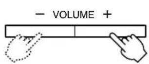
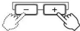
3 Adjust the volume level using VOLUME + / - (or VOL + / - on the remote control).
Pressing VOLUME ^+ (or VOL ^+ on the remote control) increases the level, while pressing VOLUME - (or VOL - on the remote control) decreases the level.
or
Remote control
Front panel
Switching the input mode
This function allows you to switch the input mode of the component connected to the DIGITAL 1 or DIGITAL 2 terminal to "Auto Mode" or "dts Fix".
Auto Mode : This recognizes the PCM signal such as a CD,
Dolby digital signal or DTS signal automatically.
dts Fix : This fixes to a DTS signal.
Normally, playback can be performed in the "Auto Mode". If you play a CD encoded with DTS in the "Auto Mode" setting, there will be a short noise at first while the unit recognizes the DTS signal and turns on the DTS decoder. Also, the dts indicator may flash when a search or skip operation is performed. If this status continues for about 30 seconds, the unit will automatically switch from the DTS-decoding mode to PCM digital signal input mode, and the dts indicator will go off. This is not a malfunction and can be avoided by setting the input mode to "dts Fix" beforehand.
When you play and stop a CD encoded with DTS in the "Auto Mode" setting, the sound is muted even if you play the PCM signal such as a normal CD and the dts indicator flashes for about 30 seconds. However, this condition is released after about 30 seconds.
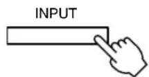
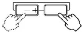
Press the INPUT selector button (or INPUT/ on the remote control) to select DIGITAL 1 or DIGITAL 2.
Front panel
or
Remote control
Press the same button again for about 3 seconds to switch the input mode.
Each time the button is pressed for about 3 seconds, the input mode is switched between "Auto Mode" and "dts Fix", and displayed as follows.
“D1← dts Fix” “D1← Auto Mode”
- "D1" or "D2" is displayed before the selected input mode when DIGITAL 1 or DIGITAL 2 is selected respectively.

- The dts indicator lights when "dts Fix" is selected, and goes off when a digital signal encoded with DTS is not input in the "Auto Mode" setting.
- The setting of the input mode returns to "Auto mode" when the power of this unit is in standby mode.
- When playing a source encoded with DTS, be sure to connect the player to the DIGITAL 1 or DIGITAL 2 input terminal of the control center with an optical fiber cable.
- If the digital output data of the player has been processed in any way, you may not be able to perform DTS decoding even if you make a digital connection between this unit and the player.
CAUTION
If a source is played back at maximum volume enough to distort the sound for a long time, the speakers may be damaged.
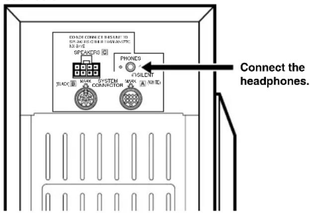
■Listening through the headphones
Connect the headphones to the PHONES jack on the rear panel of the subwoofer.
When you turn on EFFECT, the unit automatically selects the Silent Cinema program suitable for the headphones. You can enjoy the three-dimensional virtual surround even through the headphones.
Subwoofer
Note
- When disconnecting the headphones plug, confirm the location of the PHONES jack, then hold the headphones plug and pull out it. Do not pull the cord itself.
■After using the unit
Press /1 to set the unit to standby mode.
Front panel
or

Remote control
The subwoofer is also set to standby mode. To turn off the power completely, disconnect the power supply cord of the subwoofer from an AC outlet.
USING CONVENIENT FUNCTIONS
You can use convenient functions with the remote control during audio reproduction.
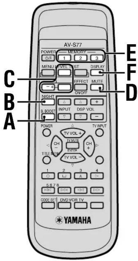
AEnhancing the bass tones
Press B. BOOST.
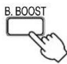
- " B. Boost ON" appears in the display.
- This function enhances the bass tones by increasing the level of the low-range frequencies.
To cancel B. BOOST mode, press B. BOOST again.
#
- The B. BOOST mode does not function when the headphones are connected.
The factory-set is "B. Boost ON".
Note
- If a thudding noise is heard from the subwoofer when this function is turned on, lower the subwoofer level. Otherwise, the subwoofer may be damaged due to an excessive input level of low-bass signal.
Listening to music clearly at low levels
Press NIGHT.

Night Mode ON" appears in the display.
- Sounds will be clear.
- Use this function when it is difficult to output high volumes such as late at night.
To cancel NIGHT mode, press NIGHT again.
中
The NIGHT mode does not function when the headphones are connected.
- The volume cannot be decreased using this button. To decrease the volume, press VOLUME - (or VOL - on the remote control).
The factory-set is "Night Mode OFF".
Adjusting the level of the subwoofer, center channel and left and right rear channels
While listening, you can adjust the sound output level of the subwoofer, center channel and left and right rear channels as desired.
1 Select the channel to be adjusted using LEVEL.
Each time you press LEVEL, the channel is selected in the following order; SWFR Center REAR-L REAR-R.
- The channel that can be adjusted will vary depending on headphones connection or selected DSP program.
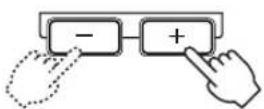
2 Adjust the sound output level by pressing + / -
To decrease the level.
To increase the level.
#
The sound output level can be adjusted in the following range. Subwoofer: -20 to +6 dB
Center channel: -20 to +3 dB
Left and right rear channels: -20 to +6dB
Rear virtual channels (when VIRTUAL SURROUND or SILENT CINEMA is selected): -3 to +3 dB
- When the sound output level is adjusted, the level adjusted with the test tone is canceled.
- We recommend that you adjust the channel level using the test tone beforehand, except the subwoofer.
- When playing back a Dolby Digital or DTS source, the sound output level of each channel should usually be adjusted to ± 0 dB or below.
Note
- If a thudding noise is heard from the subwoofer when the B. BOOST function is turned on or when you play a bass-enhanced source such as 5.1 channel Dolby Digital or DTS which contains Low Frequency Effect, lower the subwoofer level. Otherwise, the subwoofer may be damaged due to an excessive input level of low-bass signal.
DMuting the sound temporarily
Press MUTE.
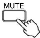

- "Mute ON" is displayed when the sound is muted.
To return to the original volume level, press MUTE again. Pressing VOL + / - also cancels the muting mode and adjusts the volume level.
E Calling Up Your Favorite Settings
Each MEMORY 1, 2 or 3 button can memorize the current input and the settings of DSP mode, subwoofer channel level, B. BOOST mode and NIGHT mode. Once the settings are preset, you can call up each MEMORY 1, 2 or 3 button anytime by simply pressing one of the MEMORY buttons.
Memorizing the settings to each MEMORY 1, 2 or 3 button
Press and hold the MEMORY 1, 2 or 3 button to be memorized for about 3 seconds.

The number of the button you pressed is displayed after "Memory" and the current settings are memorized. Ex.: When the MEMORY 1 button is pressed, "Memory 1" is displayed.
Calling up the favorite button's memory
Press the MEMORY 1, 2 or 3 button to select the desired settings.
The number of the button you pressed is displayed after "Memory" and the favorite settings are selected.
- If you keep pressing the button for more than 3 seconds, the previously memorized setting will be replaced with the current settings.
Clearing the button's memory
Press and hold the MEMORY 1, 2 or 3 button to be cleared for about 10 seconds. The number of the button you pressed is displayed after "MemoryClear" and the memorized settings are cleared. (When pressing the button, "Memory 1 (2 or 3)" is displayed after about 3 seconds, but keep pressing the button.)
- If you release the button before the display changes from "Memory" to "MemoryClear", the button memorizes the current setting.
Setting the main display
You can set the main display to "input name" or "DSP program name."
Pressing DISPLAY changes the main display between "Disp: INPUT" and "Disp: DSP."

When you operate any button, the appropriate display appears. After a few seconds, the display returns to the main display, "input name" or "DSP program name."
DSP PROGRAM (DIGITAL SOUND FIELD PROCESSING PROGRAM)
You can recreate the sound and feel of a movie theater, concert hall or other location by selecting from any of various DSP programs best suited to the source being reproduced. This allows you to enjoy the full experience of digital systems such as DOLBY DIGITAL, DOLBY PRO LOGIC, DTS, or YAMAHA CINEMA DSP (Digital Sound field Processor).
Description of DSP Programs
| No. | Program name Features and applicable sources | |
| 1-1 | VIRTUAL SURROUND (input source: Dolby Digital) | This program creates the virtual surround field that gives an experience as if you are enjoying a Dolby Digital, Dolby Pro Logic or DTS using only the main channels.(The unit selects the program from program numbers 1-1 to 1-3 appropriately according to the input source, and cannot be selected as desired.) |
| 1-2 | VIRTUAL SURROUND (input source: except the Dolby Digital/DTS) | |
| 1-3 | VIRTUAL SURROUND (input source: DTS) | |
| 2-1 | DOLBY DIGITAL (input source: Dolby Digital) | This program straightforwardly reproduces the movie sound that is accurately processed using a Dolby Digital, Dolby Pro Logic or DTS decoder.(The unit selects the program from program numbers 2-1 to 2-3 appropriately according to the input source, and cannot be selected as desired.) |
| 2-2 | DOLBY PRO LOGIC (input source: except the Dolby Digital/DTS) | |
| 2-3 | DTS (input source: DTS) | |
| 3-1 | DIGITAL MOVIE THEATER (input source: Dolby Digital) | This program reproduces the rich and full sound found in a movie theater using the latest movie sound design in which dialog and sound effects are handled separately.(The unit selects the program from program numbers 3-1 to 3-3 appropriately according to the input source, and cannot be selected as desired.) |
| 3-2 | 70mm MOVIE THEATER (input source: except the Dolby Digital/DTS) | |
| 3-3 | DTS MOVIE THEATER (input source: DTS) | |
| 4 | GAME | For directing games to be more realistic and powerful adding a depth and surround feeling to the sounds. |
| 5 | HALL | Designed to reproduce the huge image of the amphitheater, which has an all range reflection, rich and full sound, and strong surround feeling. |
| 6 | CONCERT/SPORTS | This is suitable for many types of sound reproduction such as a variety show, live broadcast program, etc. Resonant sounds are retained so that it does not give the feeling unnatural even when this sound field is used for an extended period of time. |
| 7 | MONO MOVIE | Specially designed to enhance monaural source such as an old monaural movie. Sound field effects and moderate resonance processing are used to bring fuller life to the monaural audio. |
■When the headphones are connected:
| No. | Program name Features and applicable sources | |
| 8 | SILENT CINEMA | This program is for enjoying the three-dimensional virtual surround through the headphones. This sound field is suited for multi-channel movie software such as a DVD. |
Enjoying DSP Programs

DSP selector button
Press the DSP selector button (on the control center) or DSP (on the remote control).

Front panel
or
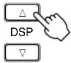
Remote control
Each time this button is pressed, the DSP program is selected in the following order and the currently selected DSP program name is displayed.
When DSP on the remote control is pressed, the DSP program is selected in reverse order.
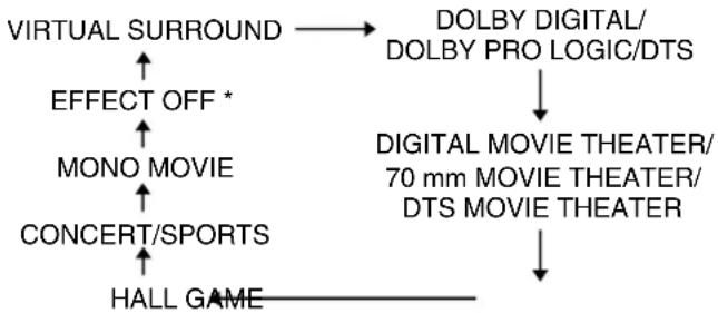
* The "EFFECT OFF" appears only when using the DSP selector button on the front speaker unit.
- When the headphones are connected:


- Be sure to select the DSP program best suited for the atmosphere of the source being listened to.
- The last selected DSP program for each input source (VIDEO, TV, AUX, DIGITAL 1 and DIGITAL 2) is stored in memory. So, when the input source is changed, the DSP program is automatically changed to the last selected one correspondingly.
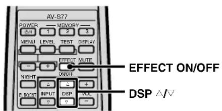
■To cancel sound field effects (using the remote control)
Press EFFECT ON/OFF.
The normal stereo playback is performed and "EFFECT OFF" is displayed when the sound field effect is canceled. Pressing this button again turns the sound field effect back on.
■Processing indicators
When reproducing a source using the DSP program, a processing indicator will light according to the functioning status of the decoder or digital sound field processor.
DIGITAL: Lights when reproducing a source encoded with Dolby Digital (5.1-channel).
PRO LOGIC: Lights when reproducing a source encoded with Dolby Digital in 2-channel, PCM audio or an analog source using DSP program No. 2-2.
Dts: Lights when reproducing a source encoded with DTS.
DSP: Lights when reproducing a source using DSP program No. 3-1 through 7.
- Depending on the input source (or signal format), the appropriate indicator may not light. Or, even between sources that are processed with the same decoding system, the different indicator may light. In the DSP program (1-1 through 3-3) that is automatically selected by this unit, the DSP program name will be displayed according to the indicator light.

- The VIRTUAL SURROUND, DOLBY DIGITAL/DOLBY PROLOGIC/DTS, DIGITAL MOVIE THEATER/70 mm MOVIE THEATER/DTS MOVIE THEATER are the optimum programs for reproducing visual software encoded with Dolby or DTS that displays the [X] [color], [DOLBY SURROUND] or [d] [no] marks.
- The volume level of the right and left main channels may differ depending on the input source being used because, except in the case of Dolby Digital and DTS, sound field data as actually measured are used.
- Select the DSP program that you feel sounds best for a source regardless of its name. Besides, the sound field effect of the DSP program is affected by the resonance of the listening room. To enjoy the full performance of the DSP program, arrange the furnishings so that your listening room has less resonance.
- Be sure to minimize the volume level of the TV to maximize the virtual surround effect when reproducing a source with the VIRTUAL SURROUND program.
MENUFUNCTIONS
The menu functions include:
"Sleep Timer" for setting the sleep timer
- "Auto Power" for setting the automatic power off
- "Dimmer" for adjusting the display brightness
- "Input Name" for naming inputs
- "Delay Time" for adjusting the delay time used for the surround sound
Adjustments on the menu functions should be performed with the remote control.
Each time MENU on the remote control is pressed, the function changes in the following order: "Sleep Timer", "Auto Power", "Dimmer", "Input Name", "Delay Time", and main display.
- When DSP program No. 3-1 through No. 7 is used, "Delay Time" is not displayed.
Setting the Sleep Timer
The unit will automatically be set to standby mode after a period of time passes.
1 Press MENU to display "Sleep Time".

Press + or - to select a desired period of time until the unit is set to standby mode.
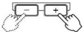
When you press + the time changes in the order, OFF, 30 min, 60 min, 90 min and 120 min. When you press - ,the time changes in reverse order.
To cancel the sleep timer, press - until "OFF" is displayed.

- If you set the unit to standby mode by pressing POWER /1 , the sleep timer will be canceled.
- To check the remaining time while the sleep timer is functioning, press MENU until "Sleep Time" appears.
When the setting is completed
After about 10 seconds, the unit returns to the main display ("input name" or "DSP program name" display). Or, press MENU until the main display appears.
Setting Auto Power Off
The Auto Power Off function works as described below.
No signal is input and no button is operated for about 30 minutes.
↓
The unit enters the Auto Power Off mode. (The STANDBY indicator lights.)
You can set the sensitivity for the Auto Power Off function or disable the Auto Power Off function.
Press MENU to display "Auto Power".

To set Auto Power Off, select the "Auto Pwr: 2" using +/- . To disable the Auto Power Off function, select the "Auto Pwr: OFF" using -.
The Auto Power Off function may not work properly depending on the signal output level of the connected component. In this case, you can refer to the table described below to change the sensitivity of the Auto Power Off function.
Pressing ^+ will change the display from top to bottom, while pressing - will change the display from bottom to top.
| Display Setting/Symptom |
| OFF The Auto power Off function is turned off. |
| 1 The unit enters the Auto Power Off mode even when the signal is being input. |
| 2 Normally select this position to turn the Auto Power Off function on. |
| 3 The unit does not enter the Auto Power Off mode even when no signal is input. |
When the setting is completed
After about 10 seconds, the unit returns to the main display ("input name" or "DSP program name" display). Or, press MENU until the main display appears.
Adjusting Display Brightness
The display brightness of the front speaker unit can be adjusted as follows.
Press MENU to display "Dimmer".
The currently brightness level (such as "Dimmer: ± 0 ") is displayed.

Press MENU + or - to adjust the brightness.
Pressing + brightens the display, while pressing - dims the display. Brightness can be adjusted from -3 (dimmest) to +3 (brightest). The brightness of +3 (brightest) is the same as that of the display right after the AV-S77 is operated.
When the setting is completed
After about 10 seconds, the unit returns to the main display ("input name" or "DSP program name" display). Or, press MENU until the main display appears.
Naming the Input Terminals
It is possible to give names to the AUX, DIGITAL 1 and DIGITAL 2 input terminals. (It is not possible to change the input names for the TV or VIDEO input terminals.)
If you select a name so that you can easily find out which component is connected to the terminal, it will be convenient when you select an input source. For example, if an MD recorder is connected to the AUX, you can name that source "MD", or if a DVD player is connected to the DIGITAL 1 terminal, you can name that source "DVD".
Press MENU to display "Input Name".

Press INPUT/ and select the input you want to name (AUX, DIGITAL 1 or DIGITAL 2).
3 Press + or - to select the name.
If you select AUX in step 2 above, names will be displayed in the following order when you press +
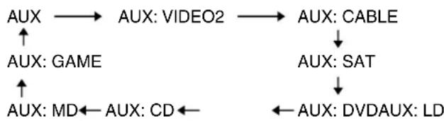
If you select DIGITAL 1 or 2 in step 2 above, names will be displayed in the following order when you press +
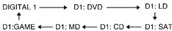

- "D1:" is displayed before the name when DIGITAL 1 has been selected, while "D2:" is displayed before the name when DIGITAL 2 has been selected.
- Pressing - displays the names in reverse order.
4 You can repeat steps 1 through 3 to give names to AUX, DIGITAL 1 and DIGITAL 2 input terminals.
When the setting is completed
After about 10 seconds, the unit returns to the main display ("input name" or "DSP program name" display). Or, press MENU until the main display appears.
Adjusting the Delay Time
When the selected DSP program is VIRTUAL SURROUND, DOLBY DIGITAL/DOLBY PRO LOGIC/ DTS or SILENT CINEMA, it is possible to adjust the delay time. The delay time is that time difference between when the sound from the main channels can be heard and the surround sound can be heard.
Setting a longer delay time makes the sound field feel larger, while setting a shorter delay time makes it feel smaller.
1 Press MENU to display "Delay Time".

Press + or - to adjust the delay time.

-
Adjustable range
-
For Dolby Digital (except for 2 ch)/DTS input:
0 to 15ms (factory setting: 5 ms)
-For the other inputs:
15 to 30ms (factory setting: 20~ms )
If the delay time level of a signal input is adjusted, that of other signal inputs will be changed. For example, when the delay time of the Dolby Digital (except for 2 ch)/DTS input is adjusted from 0ms (minimum) to 5ms , that of the other signal inputs will be adjusted from 15ms (minimum) to 20ms automatically.
When the setting is completed
After about 10 seconds, the unit returns to the main display ("input name" or "DSP program name" display). Or, press MENU until the main display appears.
Setting the manufacturer code (remote control signal assigned to each manufacturer) for your TV, VCR or DVD player on the remote control allows you to operate not only the AV-S77 but also your TV, VCR or DVD player using the remote control.
Notes
- Remote control of certain components may not be possible depending on the model and the year of make even though its manufacturer is listed on the back cover.
- Depending on the model, certain components from other manufacturers cannot be controlled, or only limited functions can be controlled, even though the proper manufacturer code has been set. If you encounter this problem, please use the remote control supplied with the component.
- Setting the manufacture code can not be performed if the component to be controlled does not support remote control operation.

- The manufacturer code 11 has been set for the remote control selector buttons (TV, VCR and DVD) at the factory.
Setting the Manufacturer Code
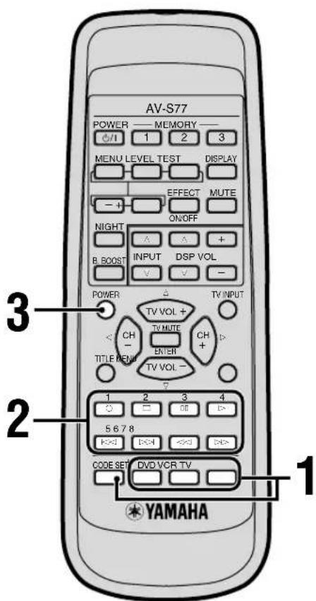
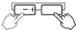
2 Keeping CODE SET pressed, enter the 2-digit manufacturer code for the component to be controlled using the numeric buttons.
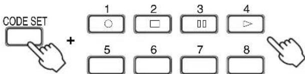

- You can release CODE SET after entering the code.
Refer to the list of manufacturer codes on the back cover.
3 Press POWER and check that the component to be controlled turns on and off (standby).

While pressing CODE SET, press the remote control selector button (TV, VCR or DVD) for which the manufacturer code is to be set.
+


V


A manufacturer code of TV, VCR or DVD can be set for the TV, VCR or DVD button respectively.
Precautions when performing the setting
You can operate the component using the TV, VCR or DVD operation buttons on the remote control once the manufacturer code is set properly. If unsuccessful, perform the procedure from step 1 again. Pay attention to the following points when you perform the procedure.
- Check that the correct remote control selector button has been selected when setting the manufacturer code.
- If more than one code is given for a manufacturer, try entering each code in the order given.
- Remove and replace the remote control's batteries (complete this step within 2 minutes) and then perform the procedure. While replacing the batteries, be sure not to press any button on the remote control. Doing so may erase the manufacturer code which has been set for other remote control selector buttons.
To reset the manufacturer code to the factory-set code
Follow steps 1 to 2 for the procedure "Setting the Manufacturer code", and enter "11" while pressing CODE SET in step 2. (It is not necessary to follow step 3.)
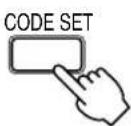
Controlling a TV
You can control your TV by setting the corresponding manufacturer code for the remote control selector button "TV".

- A VCR can be controlled using * marked buttons once the manufacturer code for that VCR has been set for the remote control selector button "VCR".
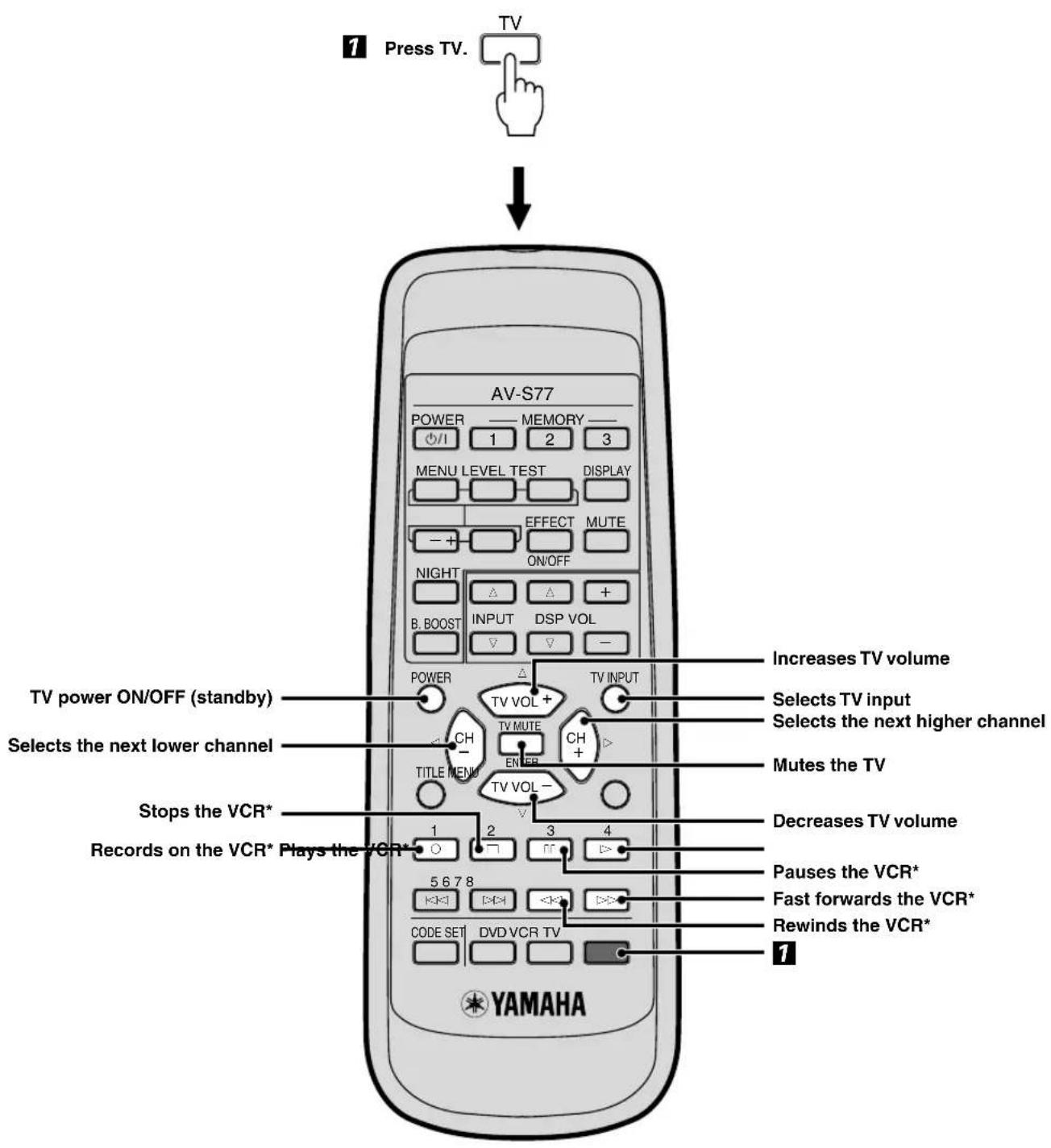
Controlling a VCR
You can control your VCR by setting the corresponding manufacturer code for the remote control selector button "VCR".

- A TV can be controlled using * marked button once the manufacturer code for that TV has been set for the remote control selector button "TV".
Controlling a DVD player
You can control your DVD player by setting the corresponding manufacturer code for the remote control selector button "DVD".
GLOSSARY
■Encode/Decode
When a signal or other information is processed, compressed and digitized, this is called encoding. Encoding can be used to record an extremely large amount of information on a single CD or DVD.
An encoded signal cannot be listened to directly. It must be returned to its original state (i.e. audible sound) and this is called decoding.
Sound field
Not all sound travels from the sound source directly into the human ear, but instead reflects off of walls, ceilings and other objects to arrive at the ear slightly delayed (early reflection). It may also reflect repeatedly in a complicated manner before reaching the ear (subsequent reverberation). A human is able to perceive the size and shape of a location based on the various sounds heard in this way. The specific acoustic space of a particular building is called a sound field.
■Dolby Surround
Dolby Surround uses a four analog channel recording system to reproduce realistic and dynamic sound effects: two left and right main channels (stereo), a center channel for dialog (monaural), and a rear channel for special sound effects (monaural). The rear channel reproduces sound within a narrow frequency range.
Dolby Surround is widely used with nearly all video tapes and laser discs, and in many TV and cable broadcasts as well. The Dolby Pro Logic decoder built into this unit employs a digital signal processing system that automatically stabilizes the volume on each channel to enhance moving sound effects and directionality.
■Dolby Digital
Dolby Digital is a digital surround sound system that gives you completely independent multi-channel audio. With three front channels (left, center and right), and two rear stereo channels, Dolby Digital provides five full-range audio channels. With an additional channel especially for bass effects, called LFE (low frequency effect), the system has a total of 5.1 channels (LFE is counted as 0.1 channel). Using two-channel stereo for the rear speakers, more accurate moving sound effects and surround sound environment are possible than with Dolby Surround. The wide dynamic range (from maximum to minimum volume) reproduced by the five full-range channels and the precise sound orientation generated using digital sound processing provide listeners with previously unheard of excitement and realism.
With this unit, any sound environment from monaural up to a 5.1-channel configuration can be freely selected for your enjoyment.
■DTS (Digital Theater Systems) Digital Surround
DTS digital surround was developed to replace the analog soundtracks of movies with a six-channel digital sound track, and is now rapidly gaining popularity in movie theaters around the world. Digital Theater Systems Inc. has developed a home theater system so that you can enjoy the depth of sound and natural spatial representation of DTS digital surround in your home. This system is a practically distortion-free, clear 6-channel sound (technically, a left, right and center channels, two rear channels, plus an LFE 0.1 channel as a subwoofer, for a total of 5.1 channels).
■LFE 0.1 channel
This channel is for the reproduction of low bass signals. The frequency range for this channel is 20Hz to 120Hz . This channel is counted as 0.1 because it only enforces a low frequency range compared to the full-range reproduced by the other 5 channels in a Dolby Digital or DTS 5.1 channel systems.
CINEMA DSP

Since the Dolby Surround and DTS systems were originally designed for use in movie theaters, their effect is best achieved in a theater with many speakers designed for acoustic effects. Since home conditions, such as room size, wall material, number of speakers, and so on, can differ so widely, it's inevitable that there are differences in the sound heard as well. Based on a wealth of actually measured data, YAMAHA CINEMA DSP uses YAMAHA original sound field technology to combine Dolby Pro Logic, Dolby Digital and DTS systems to provide the visual and audio experience of movie theater in the listening room of your own home.
■SILENT CINEMA
YAMAHA has developed a natural, realistic sound effect DSP algorithm for headphones.
Parameters only for headphones have been set so that accurate representations of the sounds can be enjoyed on headphones.
■VIRTUAL SURROUND
YAMAHA has developed a virtual CINEMA DSP algorithm that allows you to enjoy DSP sound field surround effects even without any rear speakers by using virtual rear speakers.
■PCM (Pulse Code Modulation)
PCM is a signal format under which an analog audio signal is digitized, recorded and transmitted without using any compression. Therefore, PCM may be called the liner PCM compared with the compressed audio signal such as Dolby Digital or DTS. This is used as a method of recording CDs and DVD audio. The PCM system uses a technique for sampling the size of the analog signal per very small unit of time. PCM which stands for "pulse code modulation" means that an analog signal is encoded as pulses and then modulated for recording.
TROUBLESHOOTING
Be sure to investigate the problem thoroughly before requesting repairs or after service. If the problem cannot be corrected or if it is not listed in the SYMPTOM column, disconnect the power cord and contact your authorized YAMAHA dealer or service center.
Notes
- Sometimes the unit may cease to recognize operations due to an error in operation or as a result of strong external noise (such as irregular voltage due to shock of impact, excessive static electricity, or lightning strike). If this happens, first disconnect the power cord, wait about 30 seconds, re-connect the power cord, and try the desired operation again.
- When requesting repairs or after service of the subwoofer and rear speakers, be sure to bring along the front speaker unit.
General
| SYMPTOM CHECK Refer to page | ||
| No sound output at all. | Is the AC power supply cord connected? | 19 |
| Are the two system connector cables connected correctly? | 17 | |
| Is the speaker cable connected correctly? | 17 | |
| Is the TV or VCR connected correctly? | 12-13 | |
| Is the input source selected correctly? | 22 | |
| Is the sound from AV-S77 temporarily muted? | 25 | |
| Are the headphones connected to PHONES on the rear of the subwoofer? | 23 | |
| No sound from the subwoofer. | Are the two system connector cables connected correctly? | 17 |
| Is the subwoofer level set too low? | 24 | |
| No sound from the rear speaker. | Are the speaker cables connected correctly? | 18 |
| Is the rear level set too low? | 20, 24 | |
| Is VIRTUAL SURROUND selected? | 26 | |
| Is DOLBY PRO LOGIC selected for a monaural source? | 26 | |
| No sound from the center channel. | Is the center level set too low? | 20, 24 |
| A "humming" noise is present. | Hum caused by external electromagnetic waves may be generated. | — |
| There is noise in the tuner or TV and the video image is unstable. | Is a tuner or TV that uses an indoor antenna located near the unit? Use of an outdoor antenna is recommended. | — |
| Stripes appear on the TV screen that uses an indoor antenna. | Change the direction or location of the antenna. | — |
When using a DSP program
| SYMPTOM CHECK Refer to page | ||
| Movie dialog and other audio is difficult to hear. | Is HALL, CONCERT/SPORTS or GAME selected? | 26 |
■When using the remote control
| SYMPTOM CHECK Refer to page | |
| The remote control does not function properly. | Arc the batteries used up? |
| Is the remote control pointed at the sensor? | |
| Is the remote control too far from or too close to the sensor? | |
| Is direct sunlight or other intense light (such as an inverter fluorescent lamp) striking the sensor? | |
| Is another remote control being used at the same time? | |
| Are the batteries inserted in the correct direction? | |
| Cannot control other component. | Is the manufacturer code set correctly? |
| Is the remote control selector button (TV, VCR or DVD) corresponding to the component pressed? |
SPECIFICATIONS
Amplifier Section
Maximum Output Power
Front. 25 W + 25 W (1 kHz, 10% THD, 6 Ω)
Rear. 25 W +25 W (1 kHz, 10% THD, 6 Ω)
Subwoofer .50 W (100 Hz, 10% THD, 5 Ω)
Signal-to-Noise Ratio
Total Harmonic Distortion 0.05%
(Input: AUX, 1 kHz, 12.5 W/6 Ω)
Input Sensitivity/Impedance 200 mV/50 kΩ (Input: AUX)
Speaker Section
Front Speakers
Model Name.. AV-S77C
Type Bassreflex
Speakers 8-cm cone x 2, magnetically shielded
Nominal Input Power 30 W
Impedance 6Ω
Frequency Response 120 Hz - 20 kHz
Dimensions (W× H× D) 600 x 110 x 220 mm
Weight 5.0 kg
Rear Speakers
Model Name NX-S77E
Type Acoustic suspension
Speakers 8-cm cone, magnetically shielded
Nominal Input Power 30 W
Impedance 6Ω
Frequency Response 140 Hz - 20 kHz
Dimensions (W× H× D) 100x140x112mm
Weight 0.8 kg
Subwoofer
Model Name NX-SW77
Type .... Advanced YAMAHA Active Servo Technology system
Speaker 16 cm-conc, magnetically shielded
Frequency Response 30 - 200 Hz
Dimensions (W× H× D) 176 x 405 x 433 mm
Weight 11.0 kg
General
Power Supply AC 230 V, 50 Hz
Power Consumption 120 W
Standby Power Consumption 1 W
Accessories Remote control
Batteries (x 2) (AA, R06, UM-3 type)
Connection guide
Audio connection cord (2-pin, 3 m x 1)
Speaker cable (x 1) (for the rear speakers: 15m
for the front speaker unit: 3m)
System connector cables (3 m x 2)
Fasteners (2 sets) for the front speaker unit
Parts for the rear speakers installation:
Type A brackets (x 2)
Type B brackets (x 2)
Screws (x 2)
Wing nuts (x 2)
Specifications are subject to change without notice.
INDEX
A
Adjusting display brightness 29
Adjusting the bass boost 24
Adjusting the delay time. 30
Adjusting the volume level. 22
Auto Power Off 28
AUX terminal 15
C
Channel level adjustment 20, 24
CINEMA DSP DSP program 26
Connecting a CD player 15
Connecting a DVD player 14
Connecting a TV. 12, 13
Connecting a VCR. 12, 13
Connecting an LD player. 14
Connecting an MD recorder 15
Connecting the AC power supply cord. 19
Connecting the front speaker unit, subwoofer and rear speakers 16
Controlling a DVD with the remote control 35
Controlling a TV with the remote control 33
Controlling a VCR with the remote control 34
D
Delay time Adjusting the delay time 30
DIGITAL input terminal 14, 15
Dimmer Adjusting display brightness 29
Display 4
DOLBY DIGITAL, DOLBY PRO LOGIC, DTS 26
DSP programs 26
1
Input Name Naming the input terminals 29
M
Main display 25
Manufacturer codes .i (at the end of this manual)
Manufacturer code setting 31
Memorizing/calling settings 25
Menu functions 28
Muting the sound 25
N
Naming the input terminals 29
NIGHT mode 24
s
Selecting a sound field. 27
Selecting input 22
Sleep timer setting 28
Speaker placement 6
T
Test tone 20
THROUGH OUT terminal 13
U
Using the height adjustment bracket 8
Using the speaker mounting brackets 9
Using fasteners 7
V
VIRTUAL SURROUND 26
W
Wire installation (to prevent falling) 8
ATTENTION: TENIR COMPTE DES PRECAUTIONS CI-DESSOUS AVANT DE FAIRE FONCTIONNER L'APPAREIL.
Support de montage (type A) (fourni)
AAccentuation des tons graves
Dimensions (L x H x P) 176 x 405 x 433 mm
Poids 11,0 kg
Général
Alimentation. CA 230V,50Hz
Consommation 120 W
Piles (x 2) (type AA, R06, UM-3)
Guide de connexion (Connection guide)
Cordon de raccordement audio (2 broches, 3m× 1
Supports de montage type A (x 2)
Supports de montage type B (x 2)
Vis (x 2)
Ecrous a oreilles (x 2)
Borne THROUGH OUT 13
C
CINEMA DSP Programme DSP 26
Codes fabricant .i (en fin de manuel)
Rückkanal 25 W + 25 W (1 kHz, 10% Klinrgrad, 6 Ω)
Subwoofer 50 W (100 Hz, 10% Kllrrgrad, 5 Ω)
FINESSER 1
ALLRA FÖRST 2
DELARNAS NAMN 4
HOGTALARNAS PLACERING 6
INSTALLATION 7
ANSLUTNINGAR 11
JUSTERING AV HÖGTALARNAS UTNIVÄER..20
ANVÄNDNING
HUR MAN ANVANDER APPARATEN 22
ANDRA PRACTISKA FUNKTIONER 24
DSP-PROGRAM (DIGITALA
LJUDFÄLTSBEARBETANDE PROGRAM) ...... 26
MENYFUNKTIONER 28
F
SNINNANYANV
NEETTNNNNEE
FJÄRRKONTROLLEN
HUR MAN STYR ANDRA KOMPONENTER MED FJÄRRKONTROLLEN 31
ÖVRIGHT
ORDFÖRKLARINGAR 36
FELSOKNING 38
TEKNISKA DATA 40
REGISTER 41
S
_n = 1^ anger anvandningstips.
ALLRA FÖRST
HÖGTALARNAS PLACERING
JUSTERING AV HÖGTALARNAS UTNIVÄER
■DTS (Digital Theater Systems) Digital Surround
Framre hogeatalare 25 W + 25 W (1 kHz, 10% THD, 6 Ω)
Bakre. 25 W + 25 W (1 kHz, 10% THD, 6Ω)
Subwoofer. 50 W (100 Hz, 10% THD, 5 Ω)
Signalbrusforhallende 95 dB (AUX, IHF-A)
Total harmonisk distorsion 0.05%
(Ingang: AUX, 1 kHz, 12.5 W/6 Ω)
THROUGH OUT-uttaget 13
V
Vagerupphängning (nedfallsskydd) 8
Val av ingang 22
Val av ljudfalt 27
VIRTUAL SURROUND 26
Volymjustering 22
AVVERTENZA: PRIMA DI COMINIARE AD USARE L'APPARECCHIO LEGGERE QUANTO SEGUE.
PROGRAMMA DSP (PROGRAMMI DI
CINEMA DSP CINEMADSP
(Ingresso: AUX, 1 kHz, 12.5 W/6 Ω)
Dimensioni (L x A x P) 176 x 405 x 433 mm
Peso 11,0 kg
Generali
Alimentazione CA 230V,50Hz
Consumo 120 W
Accessori Telecommando
Batterie (x 2) (formato AA, R06, UM-3)
(Entrada: AUX, 1 kHz, 12.5 W/6 Ω)
Batterijen
(AA, R06, type UM-3) (x 2)
■DTS (Digital Theater Systems) Digital Surround
(Ingang: AUX, 1 kHz, 12.5 W/6 Ω)
Ingangsgevoeligheid/Impedantic 200 mV/50 kΩ
(Ingang: AUX)
Luidsprekers
Voorluidsprekers
Modelnaam .AV-S77C
Type . basreflex
Batterijen (AA, R06, type UM-3) (x 2)
DAEWOO 17,18,24,27,28
DAYTRON 31
DUAL 18
EMERSON 17,24,31,32
FERGUSON 23,65,66
FIRST LINE 18
FISHER 15,33
FRABA 18
GE 13,17,34,35,36
GOLDSTAR 17,18,31,37
GOODMANS 16,18,23
GRUNDIG 21,38,41
HITACHI 17,31,42,43
ICE 16
IRRADIO
ITT/NOKIA 44,45
JC PENNY 13, 17, 34, 37
JVC 16,46,47
KENDO 18
KTV 17,31
LOEWE 18,48
LXI 13,17,25,26,33
MAGNAVOX 17,25,31
MATSUI 15
MITSUBISHI 11,17,51
NEC 17.52
NOKIA 44,45
NOKIA OCEANIC 45
NORDMENDE 65,66
ONWA 16
PANASONIC 34,35,36,53
PHILCO 17,25,31
PHILIPS 25
PIONEER 26,35,54,55,68
PORTLAND 17,56
QUASAR 34, 35
RADIO SHACK 11, 13, 17
RCA 13,17,34,56,57,58
SABA 23.61,65,66
SAMSUNG 17,31,48,62
SANYO 15,33,71,72,73,74
SCHNEIDER 16
SCOTT 17
SHARP 12,3
SIEMENS 21
SIGNATURE 12
SONY 63
SYLVANIA 17,25
TELEFUNKEN 61,64,65,66
THOMSON 23,66
TOSHIBA 12,26,67
VIDECH 17,42
WARD5 17,31,32
YAMAHA 11, 12
VCR
ADMIRAL 15
AKAI 22, 23, 24
AUDIO DYNAMIC 12, 14
BELL & HOWELL 13
BLAUPUNKT 25, 26
BROCSONIC 27
BUSH 22
CANON 25,28
CGM 16,32
CITIZEN 16
CRAIG
CURTIS MATHIS 17,28,33
DAEWOO 28,34,35
DBX 12.14
DIMENSIA 33
EMERSON 27,34
FISHER 13,36
FUNAI 17
GE 28,33
GOLDSTAR 16
GOODMANS 34,37
GRUNDIG 32,38
HITACHI 25,33,41,42,43
INSTANT REPLAY 25, 28
ITT/NOKIA 13
JC PENNY 12, 13, 14, 28, 33, 41
JVC 12,14,44,45,46,47
KENDO 16
KENWOOD 12,14,16
LOEWE 16,37
LUXOR 15
LXI 13,16,17,36,41
MAGNAVOX 25,26,28
MARANTZ 12,14
MARTA 16
MATSUI 16
MEMOREX 28,36
MINOLTA 33,41
MITSUBISHI 11,44,48,51,52,53
MULTITECH 17,48,54
NEC 12,14,44,83
NOKIA 13,15
NOKIA OCEANIC 15
OKANO 23
OLYMPIC 25,28
ORION 27
PANASONIC 25,28,31,55,78,84,85
PENTAX 33,41
PHILCO 25,28
PHILIPS 25,26,28,37,56,57
PHONOLA 37
PIONEER 25
QUASAR 25,28
RCA/PROSCAN 25,26,28,33,35,41,58
61
REALISTIC 13,17,28,36,51,62
SAMSUNG 54,58,63,64,65,66
SANSUI 14
SANYO 13,36,67
SCHNEIDER 37
SCOTT 11,35,36,48,51,52,54
58
SELECO 22
SHARP 15,62,82
SIEMENS 13
SIGNATURE 2000 15,17
SONY68,71,72,73,74,75
SYLVANIA 17,25,26,28
SYMPHONIC 17
TANDBERG 34
TASHIRO 16
TATUNG 12,14
TEAC 12,14,17
TECHNICS 25,28
TELEFUNKEN 76,77
THORN 13, 16
TOSHIBA 35,61,81
UNIVERSUM 16,27,76
W.WHOUSE 16
WARD5 15,16,36,62
YAMAHA 11, 12, 13, 14
DVD player
DENON 12,25
HITACHI 16
JVC 21
ONKYO 14,17,18
PANASONIC 12,15
PHILIPS 28
PIONEER 22,23,24
RCA 27
SAMSUNG 26
SONY 13
TOSHIBA 14
YAMAHA 11, 12, 28
AV-S77
Connection Guide
Connecting to a TV (monitor) with audio output terminals
AV-S77
Connection Guide
Connecting to a TV (monitor) without audio output terminals
When enjoying digital audio
- For the front speaker unit
- For the subwoofer
- ■For U.K. customers
- Note
- Special Instructions for U.K. Model
- IMPORTANT
- FEATURES
- CONTENTS
- PREPARATION
- OPERATION
- REMOTE CONTROL
- GETTING STARTED
- Checking the Package Contents
- Readying the Remote Control
- Inserting the batteries
- Precautions regarding batteries
- Preserving the manufacturer code
- Operational Area of the Remote Control
- ■Battery replacement cycle
- Precautions on handling the remote control
- NAMES OF ALL PARTS
- Front Speaker Unit (Front Panel)
- Display
- SPEAKER PLACEMENT
- ■Front speaker unit
- Rear speakers
- Subwoofer
- CAUTION
- INSTALLATION
- Installing the Front Speaker Unit
- Using the fasteners
- Precautions before installation
- Peel off the seal of the fastener with the rough surface and apply to the protrusions on the bottom of the front speaker unit.
- Place the front speaker unit where it is to be installed (ex. on top of the television) to determine where to apply the fastener with the smooth surface.
- Peel off the seal of the fastener with the smooth surface and apply to the positions determined in step 2.
- Align the fasteners on both sides and firmly press downward from the top of the front speaker unit.
- Using the height adjustment brackets
- Loosen the screws securing the adjustment bracket.
- Lower the bracket so that the front speaker unit is level and securely tighten the screws.
- To further stabilize and prevent falling
- Installing the Rear Speakers
- To mount the rear speakers on a wall using the provided mounting brackets (type A)
- Attach two commercially available protruding screws (diameter about 4mm ) in the location on the wall where the rear speaker is to be hung, and then mount the bracket on the protruding screws.
- Attach the speaker to the bracket using the provided wing nut.
- Adjust the angle of the speaker and then tighten the wing nut.
- ■To mount speakers directly to the wall
- YAMAHA speaker stand SPS-AV1 (sold separately)
- To mount the rear speakers on the commercially available speaker stands
- Attach the mounting bracket (type B) to the bottom of the speaker using the provided screw.
- Mount the speaker on the speaker stand using the bracket holes.
- CONNECTIONS
- To ensure proper connections
- Connecting a TV or VCR
- Connecting a TV (monitor) with audio output terminals
- Connecting to a TV (monitor) without audio output terminals
- When only the VIDEO terminals are connected
- When VIDEO terminals and THROUGH OUT terminals are connected
- Connecting a DVD player, etc. to Enjoy Digital Audio
- Connecting a CD Player or MD Recorder
- Connecting the Front Speaker Unit, Subwoofer and Rear Speakers
- ■Connection layout
- Connecting the front speaker unit and the subwoofer
- To remove the connector of the speaker cable
- Notes
- Connecting the rear speakers
- Connecting the AC Power Supply Cord
- Memory back-up
- Press POWER / to turn on the power.
- Press TEST.
- A: When the VIRTUAL SURROUND or SILENT CINEMA program is selected
- B: When the DSP program except the VIRTUAL SURROUND or SILENT CINEMA is selected
- Adjust the level of the test tone using VOL + / - (Adjust to your listening level.)
- Adjust the sound output level of each channel while listening to the test tone.
- In case of A
- In case of B
- OPERATING THE UNIT
- Enjoying the Home Theater Sound System
- Press /1 (or POWER /1 on the remote control) to turn on the power.
- Press the INPUT selector button (or INPUT on the remote control).
- Adjust the volume level using VOLUME + / - (or VOL + / - on the remote control).
- Switching the input mode
- Press the same button again for about 3 seconds to switch the input mode.
- ■Listening through the headphones
- ■After using the unit
- USING CONVENIENT FUNCTIONS
- AEnhancing the bass tones
- #
- Listening to music clearly at low levels
- 中
- Adjusting the level of the subwoofer, center channel and left and right rear channels
- Select the channel to be adjusted using LEVEL.
- Adjust the sound output level by pressing + / -
- DMuting the sound temporarily
- E Calling Up Your Favorite Settings
- Memorizing the settings to each MEMORY 1, 2 or 3 button
- Calling up the favorite button's memory
- Clearing the button's memory
- Setting the main display
- DSP PROGRAM (DIGITAL SOUND FIELD PROCESSING PROGRAM)
- Enjoying DSP Programs
- - When the headphones are connected:
- ■To cancel sound field effects (using the remote control)
- Press EFFECT ON/OFF.
- ■Processing indicators
- MENUFUNCTIONS
- Setting the Sleep Timer
- When the setting is completed
- Setting Auto Power Off
- Adjusting Display Brightness
- Press MENU to display "Dimmer".
- Press MENU + or - to adjust the brightness.
- Naming the Input Terminals
- Press MENU to display "Input Name".
- Press INPUT/ and select the input you want to name (AUX, DIGITAL 1 or DIGITAL 2).
- Press + or - to select the name.
- You can repeat steps 1 through 3 to give names to AUX, DIGITAL 1 and DIGITAL 2 input terminals.
- Adjusting the Delay Time
- Press MENU to display "Delay Time".
- Press + or - to adjust the delay time.
- Setting the Manufacturer Code
- Precautions when performing the setting
- To reset the manufacturer code to the factory-set code
- Controlling a TV
- Controlling a VCR
- Controlling a DVD player
- GLOSSARY
- ■Encode/Decode
- Sound field
- ■Dolby Surround
- ■Dolby Digital
- ■DTS (Digital Theater Systems) Digital Surround
- ■LFE 0.1 channel
- CINEMA DSP
- ■SILENT CINEMA
- ■VIRTUAL SURROUND
- ■PCM (Pulse Code Modulation)
- TROUBLESHOOTING
- General
- SPECIFICATIONS
- Amplifier Section
- Speaker Section
- INDEX
- A
- C
- D
- 1
- M
- N
- s
- T
- U
- V
- W
- ATTENTION: TENIR COMPTE DES PRECAUTIONS CI-DESSOUS AVANT DE FAIRE FONCTIONNER L'APPAREIL.
- AAccentuation des tons graves
- Général
- ANVÄNDNING
- FJÄRRKONTROLLEN
- ÖVRIGHT
- ALLRA FÖRST
- HÖGTALARNAS PLACERING
- JUSTERING AV HÖGTALARNAS UTNIVÄER
- AVVERTENZA: PRIMA DI COMINIARE AD USARE L'APPARECCHIO LEGGERE QUANTO SEGUE.
- CINEMA DSP CINEMADSP
- Generali
- Luidsprekers
- VCR
- DVD player
Brand : YAMAHA
Model : AVS77
Category : Home theater audio system