
YRS1100 - Home theater audio system YAMAHA - Free user manual and instructions
Find the device manual for free YRS1100 YAMAHA in PDF.
| Brand | YAMAHA |
| Model | YRS1100 |
| Product type | Home cinema audio system (Digital Sound Projector) |
| Dimensions (W × H × D) | 1200 × 500 × 445 mm |
| Weight | 46.5 kg |
| Power supply | 220-240 V AC, 50/60 Hz |
| Power consumption | 42 W |
| Standby power consumption | Less than 0.5 W (HDMI control disabled) |
| Rated output power (front L/R) | 45 W + 45 W (1 kHz, 1% THD, 6 Ω) |
| Rated output power (subwoofer) | 90 W (100 Hz, 1% THD, 3 Ω) |
| Number of speakers | 2.8 cm cone drivers (small diameter) + 6×10 cm front drivers + 13 cm subwoofer |
| Main audio features | CINEMA DSP, IntelliBeam, Dolby TrueHD, DTS-HD Master Audio, UniVolume, Music Enhancer |
| HDMI inputs | 3 (HDMI IN 1 to 3) |
| HDMI outputs | 1 (HDMI OUT with ARC) |
| Digital audio inputs | 2 optical (TV, INPUT 1), 1 coaxial (INPUT 2) |
| Analog audio input | 1 stereo pair (INPUT 3) |
| Wireless connectivity | Bluetooth (via optional YBA-10 adapter), iPod/iPhone (via optional dock station) |
| Included accessories | Remote control, batteries, optical fiber cable, digital audio cable, video cable, IntelliBeam microphone, microphone stand, installation guide, demonstration DVD, owner's manual |
| Maintenance | Clean with a dry, clean cloth. Do not use solvents. |
| Safety | Do not expose to water, do not open the casing, use specified voltage, unplug during thunderstorms. |
| Spare parts and repairability | Optional accessories available. For any repairs, contact an authorized Yamaha service. |
Frequently Asked Questions - YRS1100 YAMAHA
User questions about YRS1100 YAMAHA
0 question about this device. Answer the ones you know or ask your own.
Ask a new question about this device
Download the instructions for your Home theater audio system in PDF format for free! Find your manual YRS1100 - YAMAHA and take your electronic device back in hand. On this page are published all the documents necessary for the use of your device. YRS1100 by YAMAHA.
USER MANUAL YRS1100 YAMAHA
Surround sound TV stand
Meuble TV surround
YRS-2100
YRS-1100
OWNER'S MANUAL
MODE D'EMPLOI
IMPORTANT SAFETY INSTRUCTIONS

CAUTION
RISK OF ELECTRIC SHOCK DO NOT OPEN

CAUTION: TO REDUCE THE RISK OF ELECTRIC SHOCK,DO NOT REMOVE COVER (OR BACK).NO USER-SERVICEABLE PARTS INSIDE.REFER SERVICING TO QUALIFIED SERVICE PERSONNEL.
- Explanation of Graphical Symbols

The lightning flash with arrowhead symbol, within an equilateral triangle, is intended to alert you to the presence of uninsulated "dangerous voltage" within the product's enclosure that may be of sufficient magnitude to constitute a risk of electric shock to persons.

The exclamation point within an equilateral triangle is intended to alert you to the presence of important operating and maintenance (servicing) instructions in the literature accompanying the appliance.
IMPORTANT
Please record the serial number of this unit in the space below. MODEL:
Serial No.:
The serial number is located on the rear of the unit. Retain this
Owner's Manual in a safe place for future reference.
1 Read these instructions.
2 Keep these instructions.
3 Heed all warnings.
4 Follow all instructions.
5 Do not use this apparatus near water.
6 Clean only with dry cloth.
7 Do not block any ventilation openings. Install in accordance with the manufacturer's instructions.
8 Do not install near any heat sources such as radiators, heat registers, stoves, or other apparatus (including amplifiers) that produce heat.
9 Do not defeat the safety purpose of the polarized or grounding-type plug. A polarized plug has two blades with one wider than the other. A grounding type plug has two blades and a third grounding prong. The wide blade or the third prong are provided for your safety. If the provided plug does not fit into your outlet, consult an electrician for replacement of the obsolete outlet.
10 Protect the power cord from being walked on or pinched particularly at plugs, convenience receptacles, and the point where they exit from the apparatus.
11 Only use attachments/accessories specified by the manufacturer.
12 Use only with the cart, stand, tripod, bracket, or table specified by the manufacturer, or sold with the apparatus. When a cart is used, use caution when moving the cart/apparatus combination to avoid injury from tip-over.

13 Unplug this apparatus during lightning storms or when unused for long periods of time.
14 Refer all servicing to qualified service personnel. Servicing is required when the apparatus has been damaged in any way, such as power-supply cord or plug is damaged, liquid has been spilled or objects have fallen into the apparatus, the apparatus has been exposed to rain or moisture, does not operate normally, or has been dropped.
FCC INFORMATION (for US customers)
1 IMPORTANT NOTICE: DO NOT MODIFY THIS UNIT!
This product, when installed as indicated in the instructions contained in this manual, meets FCC requirements.
Modifications not expressly approved by Yamaha may void your authority, granted by the FCC, to use the product.
2 IMPORTANT: When connecting this product to accessories and/or another product use only high quality shielded cables. Cable/s supplied with this product MUST be used. Follow all installation instructions. Failure to follow instructions could void your FCC authorization to use this product in the USA.
3 NOTE: This product has been tested and found to comply with the requirements listed in FCC Regulations, Part 15 for Class "B" digital devices. Compliance with these requirements provides a reasonable level of assurance that your use of this product in a residential environment will not result in harmful interference with other electronic devices.
This equipment generates/uses radio frequencies and, if not installed and used according to the instructions found in the users manual, may cause interference harmful to the operation of other electronic devices.
Compliance with FCC regulations does not guarantee that interference will not occur in all installations. If this product is found to be the source of interference, which can be determined by turning the unit "OFF" and "ON", please try to eliminate the problem by using one of the following measures:
Relocate either this product or the device that is being affected by the interference.
Utilize power outlets that are on different branch (circuit breaker or fuse) circuits or install AC line filter/s. In the case of radio or TV interference, relocate/reorient the antenna. If the antenna lead-in is 300 ohm ribbon lead, change the lead-in to coaxial type cable.
If these corrective measures do not produce satisfactory results, please contact the local retailer authorized to distribute this type of product. If you can not locate the appropriate retailer, please contact Yamaha Electronics Corp., USA 6660 Orangethorpe Ave., Buena Park, CA 90620.
The above statements apply ONLY to those products distributed by Yamaha Corporation of America or its subsidiaries.
CAUTION: READ THIS BEFORE OPERATING YOUR UNIT.
1 To assure the finest performance, please read this manual carefully. Keep it in a safe place for future reference.
2 Install this unit in a well ventilated, cool, dry, clean place away from direct sunlight, heat sources, vibration, dust, moisture, and/or cold. For proper ventilation, allow the following minimum clearances. Rear: 5cm (2 in) Sides: 5cm (2 in)
3 Locate this unit away from other electrical appliances, motors, or transformers to avoid humming sounds.
4 Do not expose this unit to sudden temperature changes from cold to hot, and do not locate this unit in an environment with high humidity (i.e. a room with a humidifier) to prevent condensation inside this unit, which may cause an electrical shock, fire, damage to this unit, and/or personal injury.
5 Avoid installing this unit where foreign object may fall onto this unit and/or this unit may be exposed to liquid dripping or splashing. On the top of this unit, do not place:
- Other components, as they may cause damage and/or discoloration on the surface of this unit.
- Burning objects (i.e. candles), as they may cause fire, damage to this unit, and/or personal injury.
- Containers with liquid in them, as they may fall and liquid may cause electrical shock to the user and/or damage to this unit.
6 Do not cover this unit with a newspaper, tablecloth, curtain, etc. in order not to obstruct heat radiation. If the temperature inside this unit rises, it may cause fire, damage to this unit, and/or personal injury.
7 Do not plug in this unit to a wall outlet until all connections are complete.
8 Do not operate this unit upside-down. It may overheat, possibly causing damage.
9 Do not use force on switches, knobs and/or cords.
10 When disconnecting the power cable from the wall outlet, grasp the plug; do not pull the cable.
11 Do not clean this unit with chemical solvents; this might damage the finish. Use a clean, dry cloth.
12 Only voltage specified on this unit must be used. Using this unit with a higher voltage than specified is dangerous and may cause fire, damage to this unit, and/or personal injury. Yamaha will not be held responsible for any damage resulting from use of this unit with a voltage other than specified.
13 To prevent damage by lightning, keep the power cable disconnected from a wall outlet or this unit during a lightning storm.
14 Do not attempt to modify or fix this unit. Contact qualified Yamaha service personnel when any service is needed. The cabinet should never be opened for any reasons.
15 When not planning to use this unit for long periods of time (i.e. vacation), disconnect the AC power plug from the wall outlet.
16 Be sure to read the "TROUBLESHOOTING" section on common operating errors before concluding that this unit is faulty.
17 Before moving this unit, press to set this unit to the standby mode, and disconnect the AC power plug from the wall outlet.
18 Install this unit near the AC outlet and where the AC power plug can be reached easily.
19 The batteries shall not be exposed to excessive heat such as sunshine, fire or the like. When you dispose of batteries, follow your regional regulations.
20 Excessive sound pressure from earphones and headphones can cause hearing loss.
This unit is not disconnected from the AC power source as long as it is connected to the wall outlet, even if this unit itself is turned off by . This state is called the standby mode. In this state, this unit is designed to consume a very small quantity of power.
WARNING
TO REDUCE THE RISK OF FIRE OR ELECTRIC SHOCK, DO NOT EXPOSE THIS UNIT TO RAIN OR MOISTURE.
CAUTION
Danger of explosion if battery is incorrectly replaced. Replace only with the same or equivalent type.
CAUTION
Use of controls or adjustments or performance of procedures other than those specified herein may result in hazardous radiation exposure.
Notes
- This unit's speakers use magnets. Do not place items that are sensitive to magnetism, such as CRT-type TVs, clocks, credit cards, floppy disks, etc., on top of the rack.
- When the unit is positioned close to a CRT-type TV, picture or sound distortion may occur. In this case, movc the TV away from the unit.
FOR CANADIAN CUSTOMERS
To prevent electric shock, match wide blade of plug to wide slot and fully insert.
This Class B digital apparatus complies with Canadian ICES-003.
■For U.K. customers
If the socket outlets in the home are not suitable for the plug supplied with this appliance, it should be cut off and an appropriate 3 pin plug fitted. For details, refer to the instructions described below.
Note
The plug severed from the mains lead must be destroyed, as a plug with bared flexible cord is hazardous if engaged in a live socket outlet.
Special Instructions for U.K. Model
IMPORTANT
THE WIRES IN MAINS LEAD ARE COLOURED IN ACCORDANCE WITH THE FOLLOWING CODE:
Blue: NEUTRAL
Brown: LIVE
As the colours of the wires in the mains lead of this apparatus may not correspond with the coloured markings identifying the terminals in your plug, proceed as follows:
The wire which is coloured BLUE must be connected to the terminal which is marked with the letter N or coloured BLACK. The wire which is coloured BROWN must be connected to the terminal which is marked with the letter L or coloured RED. Making sure that neither core is connected to the earth terminal of the three pin plug.
Notes on remote controls and batteries
- Do not spill water or other liquids on the remote control.
- Do not drop the remote control.
- Do not leave or store the remote control in the following places:
- places of high humidity, such as near a bath
- places of high temperatures, such as near a heater or a stove
- places of extremely low temperatures
- dusty places
- Do not expose the remote control sensor of this unit to direct sunlight or lighting such as inverted fluorescent lamps.
- If the batteries grow old, the effective operation range of the remote control decreases considerably. If this happens, replace the batteries with two new ones as soon as possible.
- Change all of the batteries if you notice the following conditions: the operation range of the remote control decreases or the transmission indicator does not light up or becomes dim.
- Do not use old batteries together with new ones.
- Do not use different types of batteries (such as alkaline and manganese batteries) together. Read the packaging carefully as these different types of batteries may have the same shape and color.
- Exhausted batteries may leak. If the batteries have leaked, dispose of them immediately. Avoid touching the leaked material or letting it come into contact with clothing, etc. Clean the battery compartment thoroughly before installing new batteries.
- Do not throw away batteries with general house waste. Dispose of them correctly in accordance with your local regulations.
We Want You Listening For A Lifetime
Yamaha and the Electronic Industries Association's Consumer Electronics Group want you to get the most out of your equipment by playing it at a safe level. One that lets the sound come through loud and clear without annoying
blaring or distortion – and, most importantly, without affecting your sensitive hearing.
Since hearing damage from loud sounds is often undetectable until it is too late, Yamaha and the Electronic Industries
Association's Consumer Electronics Group recommend you to avoid prolonged exposure from excessive volume levels.

LISTENING
Contents
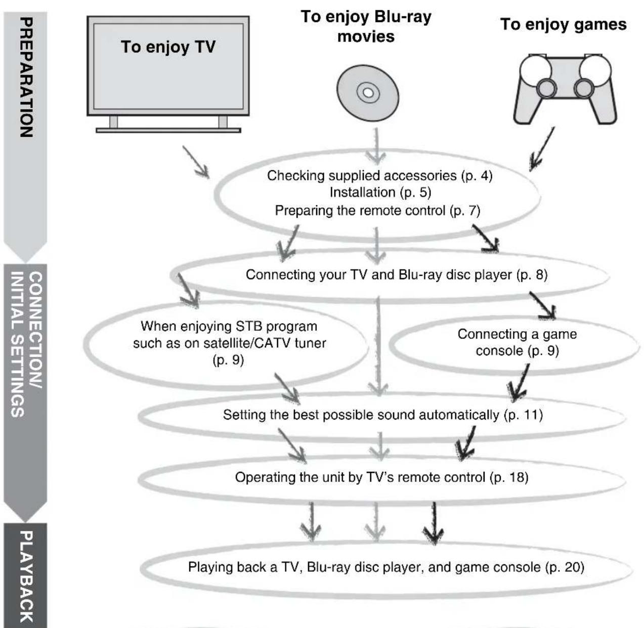
PREPARATION
Getting started 4
Supplied accessories 4
CONNECTION/INITIAL SETTINGS
Installation. 5
Remote control preparation. 7
Connections. 8
TV and Blu-ray disc player connection. 8
Game console or tuner connection 9
Initial settings. 10
Selecting language for menu display 10
Auto setup for appropriate surround effects (IntelliBeam). 11
Operating the unit by TV's remote control. 18
PLAYBACK
Playback features 20
Basic operation for playback. 20
Enjoying sound with your preference. 21
Switching stereo/surround sound. 21
Playing back digitally compressed formats (MP3, WMA, etc.)
with enriched sound (Compressed Music Enhancer) 21
Automatic volume level adjustment (UniVolume) 21
Volume balance adjustment. 21
Enjoying realistic surround sound (CINEMA DSP) 22
Changing the audio output method for surround playback.....23
Surround decoder setting. 25
Using useful features 26
Listening with headphones. 26
Sleep timer/auto power down function 27
Settings for each input source (Option menu) 27
Playing back iPod/Phone 29
When using Yamaha Universal Dock for iPod (optional YDS-12, etc.) 29
When using Wireless System for iPod (optional YID-W10)....29
Playing back Bluetooth components. 30
Pairing 30
Connecting 31
SETTINGS
Setup menu. 32
Setting procedure. 32
Setup menu list. 33
Manual setup. 34
Setting parameters 34
Beam adjustment 35
Image location 36
Tone control 36
Tone control. 36
Subwoofer settings 36
Audio delay control 36
Dynamic range control. 37
Volume level of each channel with test tones 37
Sound out setting 37
Sound beam output configuration 37
Input assignment 38
Input assignment 38
Input rename 39
HDMI setup. 39
DISPLAY MENU 40
Advanced setup 41
TROUBLESHOOTING
Troubleshooting. 42
ABOUT THIS UNIT
Controls and functions. 46
Glossary. 49
Specifications. 51
Using the supplied demonstration DVD. 53
Index. 54
About this manual
- In this manual, operations that can be performed using either the front panel buttons or the remote control are explained using the remote control.
- indicates a tip for your operation.
Notes contain important information and operating instructions. - This manual is produced prior to production. Design and specifications are subject to change in part as a result of improvements, etc. In case of differences between the manual and the product, the product has priority.
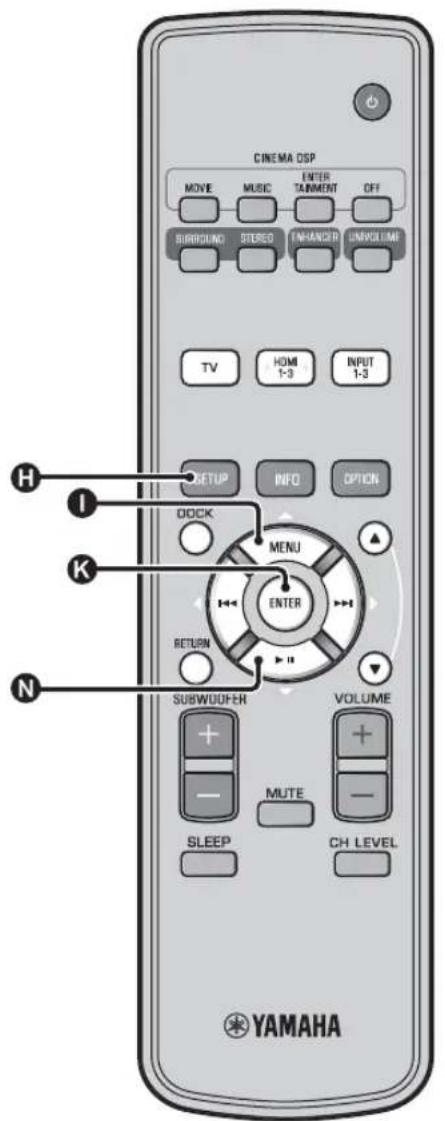
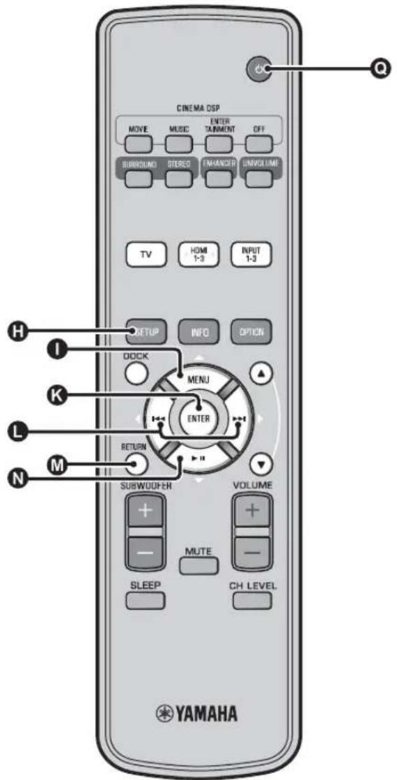
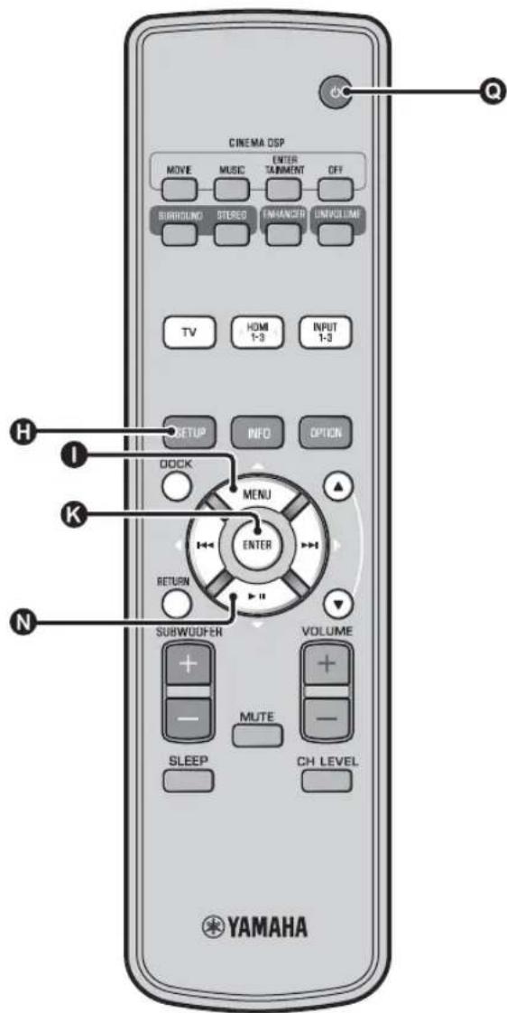
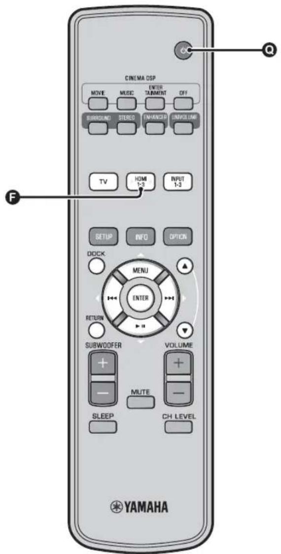
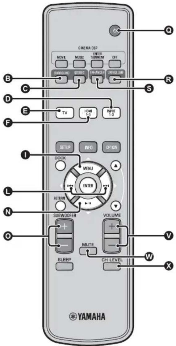
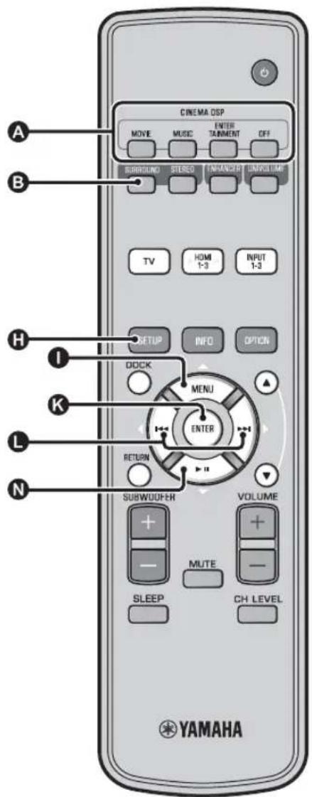
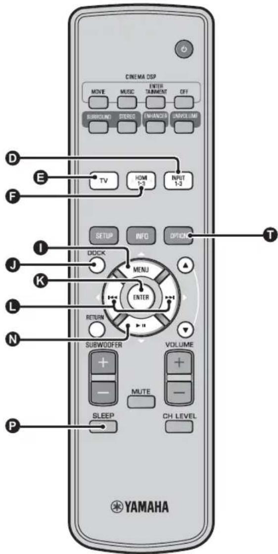
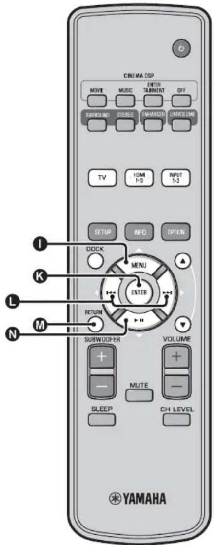
The alphabet mark (such as ) indicates the remote control key(s) indicated on the figure on the left page.
Getting started
Supplied accessories
Before assembly and connecting, make sure you have received all of the following items. 1)
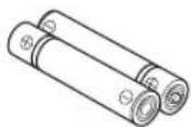
Remote control Battery (× 2)
(AA, R6, UM-3)
Optical cable
(1.5 m (4.9 ft))
Digital audio pin cable
(1.5 m (4.9 ft))
Video pin cable
(for displaying menu and iPod video)
(1.5 m (4.9 ft))


IntelliBeam microphone
(× 1) (6 m (19.7 ft))
Cardboard microphone
stand (× 1)


Install Manual

Quick Reference Guide
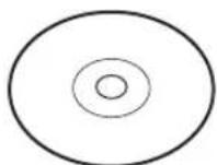
Demonstration DVD
(p. 53)

Owner's Manual
(this manual)
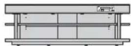
Main unit
Assembly is required before using this unit. Make sure all of the following items are included in the package, as they are all necessary to complete assembly. Refer to the Install Manual for installation.
- Main unit - Rear panels (left and right)
- Shelf - Support posts
- Bottom panel - Center rear panel
Glass top panel Brackets - Pins - Small screws M4 × 10 mm
Large screws M5× 30mm - Washers
Fasteners
Installation
Place the unit in the appropriate position after assembly. Refer to the supplied Install Manual for assembly. This section describes a suitable installation location to install this unit. Refer to "Notes on installation" below and place the unit correctly in the safe place.
Notes on installation
- Install your TV in accordance with the manufacturer's instructions to prevent it from toppling over.
This unit's speakers use magnets. Do not place items that are sensitive to magnetism, such as clocks, credit cards, floppy disks, etc., on top of the rack. - When the unit is positioned close to a CRT-type TV, picture or sound distortion may occur.
Caution: Handling the tempered glass
The top glass panel is constructed of glass that has been tempered for strength and safety. In addition, a safety film has been applied to the tempered glass to offer additional protection against injuries that may be caused by shattering glass. However, if you handle the glass inappropriately, the glass might break and glass fragments might fly, causing injuries. Be sure to follow the precautions listed below:
- Do not allow any strong impacts to the glass (for example, do not allow thrown objects to strike the glass).
- Do not allow sharp objects to contact the glass.
If the tempered glass has been scratched, it might break unexpectedly. If you see scratches, replace the glass immediately. - Do not remove the glass caution sticker.
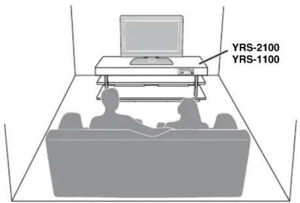
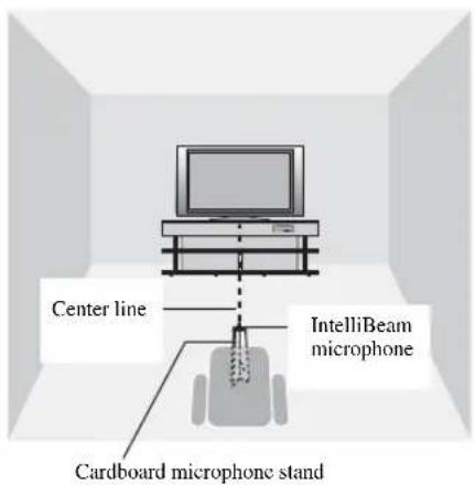
Install this unit in the center of the left and right walls.
- Listening position (such as sofa, etc.) should be located at the front of the unit.
The distance between listening position and the unit should be more than 1.8m (6 ft).
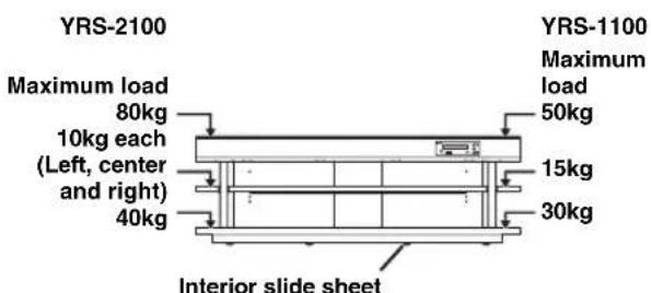
An interior slide sheet is attached to the bottom of the unit, allowing you to move the unit into position easily. To prevent damage to the floor, clean the floor of dust and rubbish before moving the unit.
Before installing this unit
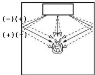
This unit creates surround sound by reflecting projected sound beams off the walls of your listening room. The surround sound effects produced by this unit may not be sufficient when this unit is installed in the following locations.
Rooms with walls inadequate for reflecting sound beams
Rooms with acoustically absorbent walls
- Rooms with measurements outside the following range: W (3 to 7 m (10 to 23 ft)) × H (2 to 3.5 m (7 to 11.5 ft)) × D (3 to 7 m (10 to 23 ft))
Rooms with less than 1.8m (6 ft) from the listening position to this unit
- Rooms where objects such as furniture are likely to obstruct the path of sound beams
Rooms where the listening position is close to the walls
Rooms where the listening position is not in front of this unit
My Surround
In the room such as above, you can enjoy rich surround effects by My Surround (p. 24).
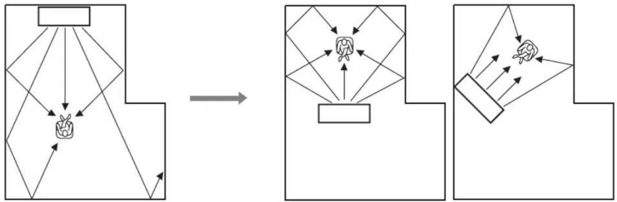
Installing this unit
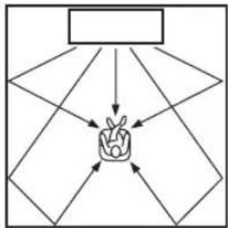
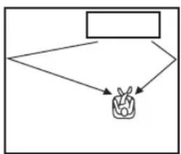
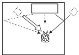
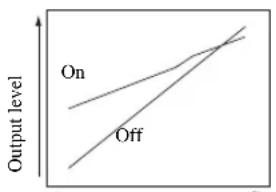
This unit outputs sound beam as shown in the illustrations below. Install this unit where there are no obstacles such as furniture obstructing the path of sound beams. Otherwise, the desired surround sound effects may not be achieved.
You may install this unit in parallel with the wall or in the corner.
Parallel installation
Install this unit in the exact center of the wall when it is measured from the left and right corners
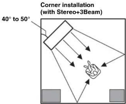
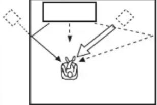
Corner installation
Install this unit in the corner at a 40^ to 50^ angle from the adjacent walls.

An object, such as furniture

■Installation examples
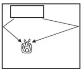
Parallel installation
Install this unit as close to the exact center of the wall as possible.
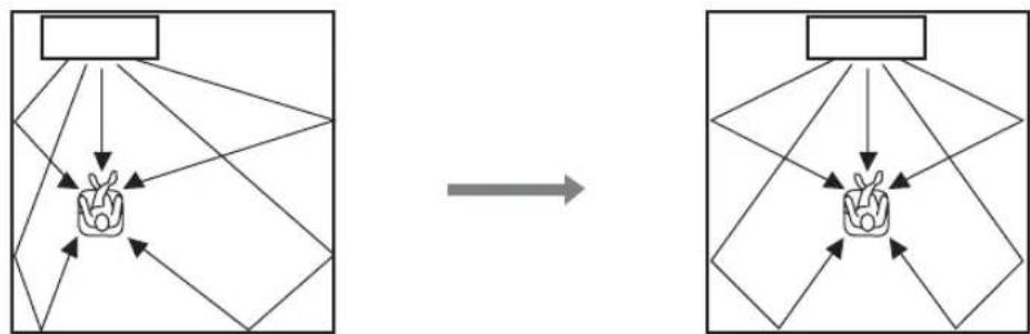
Ideal installation condition
Install this unit as close to the exact front of your normal listening position as possible.
The distance between listening position and the unit should be more than 1.8m (6 ft).
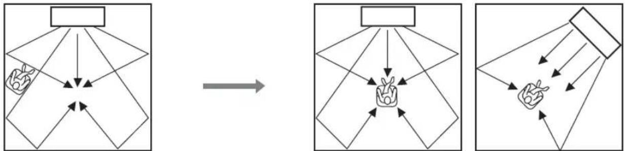
Installing in a non-square room
Install this unit so that the sound beams can be reflected off the walls.
Remote control preparation
Before installing batteries or using the remote control, make sure that you read precautions on the remote control and batteries in "CAUTION: READ THIS BEFORE OPERATING YOUR UNIT."
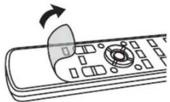
Installing the batteries
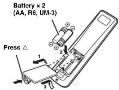
Remove the transparent sheet before using.
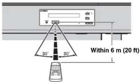
Operation range
- Do not connect the power cable until all connections are completed.
- Do not use excessive force when inserting the cable plug. Doing so may damage the cable plug and/or terminal.
TV and Blu-ray disc player connection
For the cable connection, follow the orders below.
1 HDMI cable (optional)
Input the digital audio/ video signals of the Blur ray disc player to this unit.
2 HDMI cable (optional)
The digital video of the Blu-ray disc is reflected on TV.
3 Optical cable (supplied)
Play back digital sounds of TV on this unit.
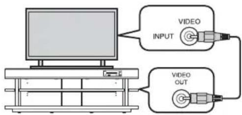
4 Video pin cable (supplied)
To display the YRS-2100/YRS-1100's setup menus on the TV.
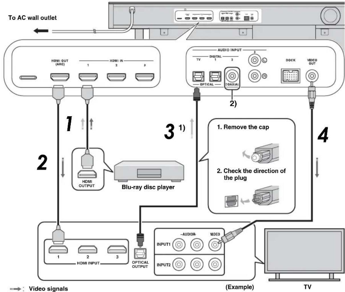
Video signals
Audio signals

Audio return channel (ARC) supported TV
- Connect HDMI cable to audio return channel supported terminal (the terminal with "ARC" indicated) on TV. In this case, you do not need to connect optical cable.
Activate the HDMI control function of this unit (sp. 39).
What is audio return channel (ARC)?
A function transmits digital audio signal output from TV to this unit through a HDMI cable. By this function, a digital audio pin cable to connect TV and this unit is not needed.

Depending on the setting, HDMI for video signal and optical digital audio, coaxial digital audio or analog audio for audio signal can be selected. Refer to "Input assignment (es'p. 38)".
Game console or tuner connection
| Additional external device (example) Connecting cable | |
| ① HDMI supported game console | HDMI cable (optional) |
| ② Satellite/cable TV (HDMI supported) | HDMI cable (optional) |
| ③ Satellite/cable TV (HDMI not supported) | Digital audio pin cable (supplied) 4) |
| ④ HDMI not supported game console | Analog audio stereo pin cable (optional) 4) |
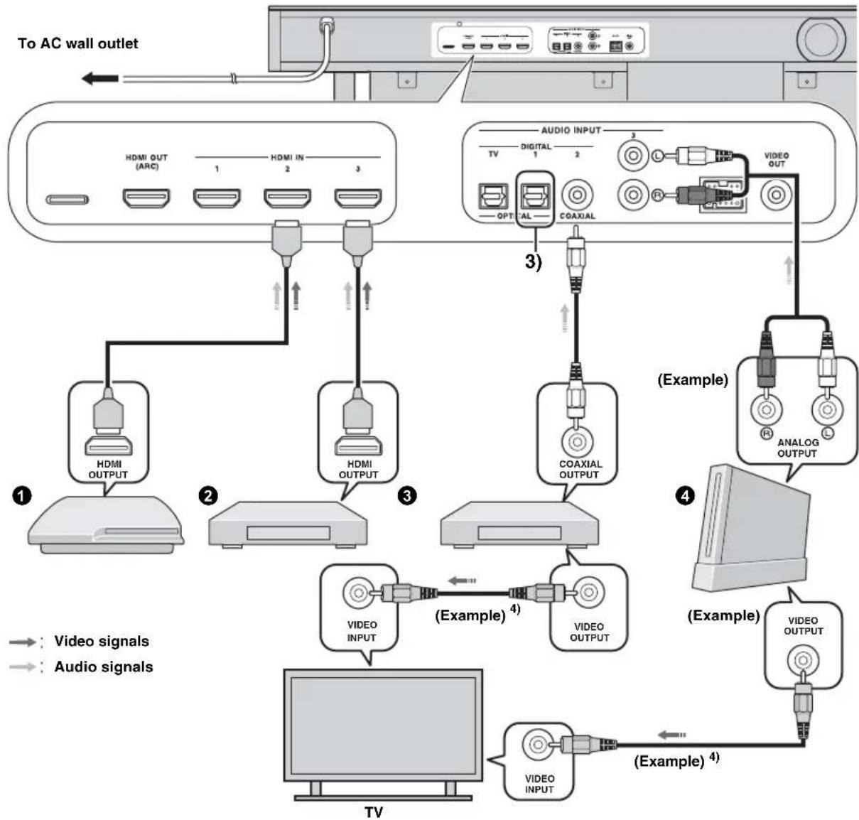

The additional devices having an optical digital output jack, connect to the optical digital input jack of this unit with an optical cable.
To connect a game console or tuner to TV, you need extra video pin cables (optional).
Selecting language for menu display
1 Turn the unit and your TV on.
2 Switch TV's input to "VIDEO INPUT 1 (example)".
example)
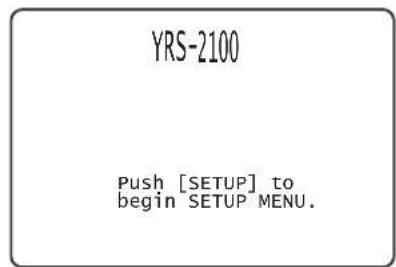
Check whether the initial screen is displayed. 1)
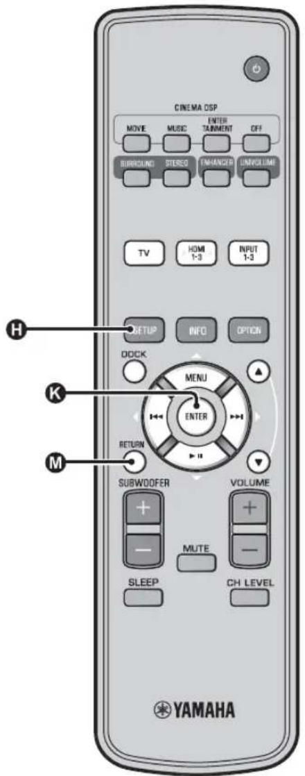
3 Press and hold SETUP key until the "LANGUAGE SETUP" menu appears on your TV.
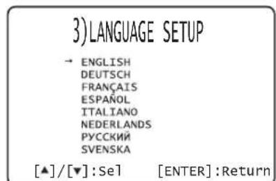
4 Press / key to select the desired language and then press ENTER key.
Selectable item: ENGLISH, DEUTSCH, FRANÇAIS, ESPÁÑOL, ITALIANO, NEDERLANDS, PYCCKÍN, SVENSKA
Initial setting: English
Auto setup for appropriate surround effects (IntelliBeam)
This unit creates a sound field by reflecting sound beams on the walls of your listening room and by broadening the cohesion of all the channels. Just as you would arrange the speaker position of other audio systems, you need to set the beam angle to enjoy the best possible sound from this unit.
This unit employs the beam optimization and sound optimization features with the aid of the supplied IntelliBeam microphone, allowing you to avoid troublesome listening-based setup and achieving highly accurate sound adjustments that best match your listening environment. We call these two features "IntelliBeam" generically.
Beam optimization:
This feature optimizes the beam angle so that the parameter best matches your listening environment.
Sound optimization:
This feature optimizes the beam delay, volume, and quality so that the parameters best match your listening environment. This unit performs these two automatic optimizations with the aid of the supplied IntelliBeam microphone. 2)

Note
- The AUTO SETUP procedure may not be run successfully if this unit is installed in one of the rooms described in "Installing this unit" on page 6. In such cases, run MANUAL SETUP (http://p.14) to manually adjust the corresponding parameters.
- Do not connect the IntelliBeam microphone to an extension cable as doing so may result in an inaccurate sound optimization.
After you have completed the AUTO SETUP procedure, be sure to disconnect the IntelliBeam microphone. - The IntelliBeam microphone is sensitive to heat.
- Keep the IntelliBeam microphone away from direct sunlight.
- Do not place the IntelliBeam microphone on top of this unit.
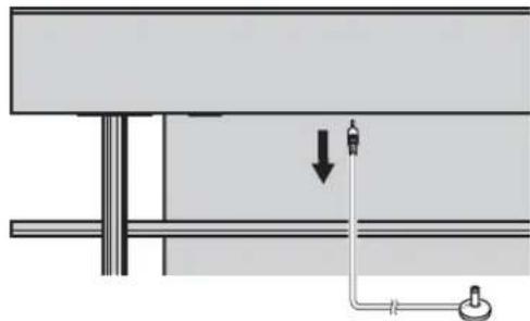
Installling the IntelliBeam microphone
Follow the procedure below to connect the IntelliBeam microphone to this unit and place it in a proper location.
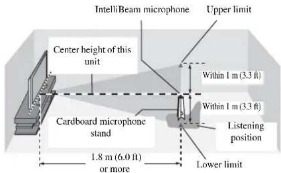
1 Place the IntelliBeam microphone on a flat level surface at your normal listening position.
Use the supplied cardboard microphone stand or a tripod to place the IntelliBeam microphone at the same height as your ears would be when you are seated.
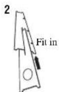
■Assembling the supplied cardboard microphone stand

1

Place 4 horizontally


Make sure that there are no obstacles between the IntelliBeam microphone and the walls in your listening room as these objects obstruct the path of sound beams. However, any objects that are in contact with the walls will be regarded as a protruding part of the walls.
2 Check if a supplied video pin cable is connected and headphones are not connected.

-
"BEAM+SOUND OPTIMIZE" screen appears automatically when the IntelliBeam microphone is connected. "BEAM OPTIMIZE ONLY" or "SOUND OPTIMIZE ONLY" can be selected separately in setup menu (p. 14).
-
Data set automatically can be saved in the system memory (v.p. 16). You can save the several data depending on listening room and you can change the setting conveniently.
Using AUTO SETUP (IntelliBeam)
Note
It is normal for loud test tones to be output during the AUTO SETUP procedure. Make sure that there are no children around in the listening room while the AUTO SETUP procedure is in progress.
Make sure that your listening room is as quiet as possible. For accurate measurement, turn off air conditioner or other devices that make noises.
- If there are curtains in your listening room, we recommend following the procedure below.
1 Open the curtains to improve sound reflection.
2 Run "BEAM OPTIMIZE ONLY".
3 Close the curtains
4 Run "SOUND OPTIMIZE ONLY".
1 Turn the unit and your TV on.
2 Switch TV's input to "VIDEO INPUT 1 (example)".
3 Connect the supplied IntelliBeam microphone to the INTELLIBEAM MIC jack.
The jack is on the underside of the main unit.
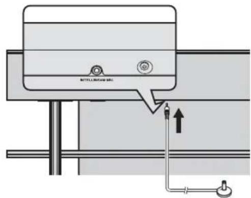
IntelliBeam microphone
1)=2)
When pressing RETURN key displays the setup menu
Press SETUP key repeatedly and display the menu screen again, then select: "AUTO SETUP" → "BEAM+SOUND OPTIMIZE".
When the screen is not displayed
Confirm the case below.
- The input jack of your TV and the video output jack of the unit are connected.
- The input of your TV is set to "VIDEO INPUT 1 (example)".
"BEAM+SOUND OPTIMIZE" is selected automatically. When you perform "BEAM OPTIMIZE ONLY" or "SOUND OPTIMIZE ONLY" only, refer to "AUTO SETUP via setup menu (sp. 14)".
3)
- Wait outside the room during the AUTO SETUP procedure.
The AUTO SETUP procedure takes about 3 minutes. - To cancel the AUTO SETUP procedure after it is started, press
RETURN key.
The screen below is displayed after connecting IntelliBcam microphone to the unit. 1) 2)
AUTO SETUP
(PREPARATION & CHECK)
Please connect the MIC. Please place the MIC at least 1.8m/6ft away from SoundPro
The MIC should be set at ear level when seated.
Measurement takes about 3min. After ENTER is pressed,
please leave the room.

Note
The best setting may not be done if you are in the room. Prepare to leave the room in 10 seconds after pressing NTER in step 4.
4 Press ENTER key to start the AUTO SETUP procedure and then leave the room within 10 seconds.3)
The setup screen automatically changes during the AUTO SETUP procedure.
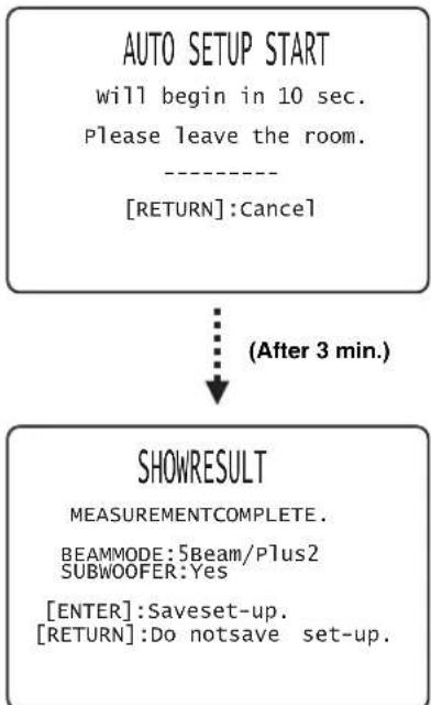
If AUTO SETUP procedure is complete, this unit rings the chimes. 4)

Press ENTER key to confirm the results. 5)
The measurement result is saved.
AUTO SETUP COMPLETE
Please remove the MIC from Sound Projector and the listening position.

Remove the IntelliBeam microphone.
Initial screen appears. 6)
Keep the IntelliBeam microphone in a safe place.
The measurement results are stored in the internal memory of this unit until you run the AUTO SETUP procedure again or configure the settings manually. You can save the several measurement result using memory setting function (e p. 16).
4)÷5)÷
- If an error occurs, an error buzzer sounds and an error message is displayed. For details on error messages, see "Error messages for AUTO SETUP" (e.p. 15).
- If "ENVIRONMENT CHECK:Failure" is displayed, refer to "Error messages for AUTO SETUP" (1p. 15), press RETURN key, and then run the AUTO SETUP procedure again.
- Depending on the environment of your listening room, the beam angles of front right and left and surround left and right may be set to the same value even if "BEAM MODE :5 Beam" is displayed as a result.
If you do not want to reflect the results, press RETURN key.
6)
When AUTO SETUP is performed from SETUP MENU, menu selection screen of SETUP MENU appears.
AUTO SETUP via setup menu
1 Place the IntelliBeam microphone and press SETUP key.
2 Press 1 / N to select "AUTO SETUP" and then press ENTER key.
3 Press / to select one of the items below and then press ENTER key.
Select Item:
"BEAM+SOUND OPTIMIZE" (Beam optimization and sound optimization)
It is recommended that you should select this optimization feature, if you make settings for the first time.
This menu takes about three minutes.
"BEAM OPTIMIZE ONLY"(Beam optimization only)
Use to optimize the beam angle so that the parameter best matches your listening environment.
This menu takes about one minute.
"SOUND OPTIMIZE ONLY"(Sound optimization only)
Use to optimize the beam delay, volume, and quality so that the parameters best match your listening environment.
You must optimize the beam angle with "BEAM OPTIMIZE ONLY" before starting "SOUND OPTIMIZE ONLY". It is recommended that you should select this optimization feature in the following cases:
If you have opened or closed the curtains in your listening room before using this unit
- If you have manually set the beam angle.
This menu takes about two minutes.
4 Connect the IntelliBeam microphone to this unit after "AUTO SETUP (PREPARATION & CHECK)" screen is displayed.
For the details on installing and connecting IntelliBeam microphone, refer to "Installing the IntelliBeam microphone (p. 11)".
Note
The best setting may not be done if you are in the room. Prepare to leave the room in 10 seconds after pressing NTER in step 4.
5 Perform the step 4, 5 and 6 of "Using AUTO SETUP (IntelliBeam) (p. 13)".
6 After setup is completed, remove the IntelliBeam microphone.
■Error messages for AUTO SETUP
If an error message is displayed on your TV, check the error message list to solve the problem and then follow the procedure below.
[ERROR E-1]: Press ENTER key to run the AUTO SETUP procedure again. Or press key to continue the measurement.
[ERROR E-7]: Press to turn this unit to standby mode, then run AUTO SETUP procedure again after turning this unit on.
Other errors: Press RETURN key to cancel the operation and then run the AUTO SETUP procedure again. If the problem is difficult to be solved, configure the settings manually in "SETUP MENU" (p. 32).
| ERROR E-1: Please test in quieter environment. | |
| Cause Remedy | |
| There is too much unwanted noise in your listening room. | Make sure that your listening room is as quiet as possible. You may want to choose certain hours during the day when there is not much noise coming from outside. |
| ERROR E-2: No MIC detected. Please check MIC connection and re-try. | |
| Cause Remedy | |
| The IntelliBeam microphone is not connected to this unit or disconnected during the AUTO SETUP procedure. | Connect the IntelliBeam microphone to this unit firmly. |
| ERROR E-3: Unexpected control is detected. Please re-try. | |
| Cause Remedy | |
| Some other operations were performed on this unit while the AUTO SETUP procedure was in progress. | Do not perform any other operations while the AUTO SETUP procedure is in progress. |
| ERROR E-4: Please check MIC position. MIC should be set in front of the Sound Projector and re-try. | |
| Cause Remedy | |
| The IntelliBeam microphone is not placed in front of this unit. | Make sure that the IntelliBeam microphone is installed in front of this unit. |
| ERROR E-5: Please check MIC position. MIC should be set above 1.8m/6.0ft and re-try. | |
| Cause Remedy | |
| The IntelliBeam microphone is not placed in the right distance from this unit. | Make sure that the IntelliBeam microphone is installed more than 1.8 m (6.0 ft) from the front of this unit and within 1 m (3.3 ft) from the center height of this unit. |
| ERROR E-6: Volume level is lower than expected. Please check MIC position/connection and re-try. | |
| Cause Remedy | |
| The IntelliBeam microphone cannot collect the sound produced by this unit because the sound output level is too low. | Make sure that the IntelliBeam microphone is firmly connected to this unit and placed in a proper location. If the problem persists, contact the nearest authorized Yamaha service center for assistance. |
| ERROR E-7: Unexpected error happened. Please turn off and re-try. | |
| Cause Remedy | |
| An internal system error occurred. | Press OK to turn this unit to standby mode, then run AUTO SETUP procedure again after turning this unit on. |
| ERROR E-8: Headphones are connected. Please unplug the headphones and re-try. | |
| Cause Remedy | |
| A head phone is connected. Disconnect | ect the head phone and re-try. |
Saving several measurement results (Memory setting function)
You can save the current beam and sound settings in the system memory of this unit. It is handy to save certain settings according to the varying conditions of your listening environment. For example, if there are curtains in the path of sound beams, the effectiveness of the sound beams will vary depending on whether the curtains are open or closed.
If there are curtains in your listening room, we recommend following the procedure below.
- While the curtains are open, run "BEAM+SOUND OPTIMIZE" (p. 14) and then save the settings to "Memory 1".
- While the curtains are closed, run "SOUND OPTIMIZE ONLY" (p. 14) and then save the settings to "Memory 2".
Saving settings
1 Press SETUP key.
2 Select "MEMORY" and press ENTER key.
3 Press 1 / key to select "SAVE" and then press ENTER key.
4 Press / key to select the desired memory number and then press ENTER key. 1)
Selectable item: Memory 1, Memory 2, Memory 3 "Memory 1 Save Now ?" is displayed when the memory number is selected.
Press ENTER key.
"Memory 1 Saving..." is displayed and the setting is saved.
1) = 19
- If system settings are already stored in the selected memory number, this unit overwrites the old settings.
- Memory function cannot be set when "MEMORY PROTECT" is set to "ON" in ADVANCED SETUP (p.41).
■Loading settings
1 Press ⑤SETUP key.
2 Select "MEMORY" and press ENTER key.
3 Press 0 /N key to select "LOAD" and press ENTER key.
4 Press / key to select the memory number to be loaded and then press ENTER key.
Selectable item: Memory 1, Memory 2, Memory 3
"Memory 1 Load Now ?' is displayed when the memory number is selected.
5 Press ENTER key.
"Memory 1 Loading..." is displayed and the setting is loaded.
Operating the unit by TV's remote control
What is the HDMI control function?
You can use the TV remote control to operate this unit if your TV supports the HDMI control function (ex. REGZA Link) and is connected to this unit's HDMI OUT (ARC) jack. 1)
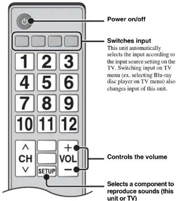
Remote control of TV (Example)
1)
Even if your TV supports the HDMI control function, some functions may not be available. For details, refer to the manual supplied with your TV.
- If you use HDMI to connect this unit to a device such as a Blu-ray disc player that supports HDMI control, you can control that device using the HDMI control function.
- We suggest that you use products (TV, Blu-ray disc/DVD player, etc.) from the same manufacturer.
Setting the HDMI control function
1 Turn on all components connected to this unit with HDMI.
2 Check all components connected with HDMI and enable the HDMI control function on each component.
For this unit, set "HDMI CONTROL" to "ON" (p. 39). For external components, refer to the manual supplied with each component.
3 Turn off the TV and then turn on it again.
Registering HDMI components to TV 4)
1 Select this unit as the input source of the TV.
2 Turn on the HDMI control function supported component (example: Blu-ray disc player) connected to this unit.
3 Select the input source of this unit to Blur ray disc player and check whether the image in the player is correctly displayed or not.
When connecting Blu-ray disc player with HDMI 1 jack, press Fput selector key once to show the following diagram.
Input source name
HDM1
4 Check if the HDMI control function works (turn on this unit or adjust the volume level using the remote control of the TV).
If the HDMI control function is not working
Check the following:
- The TV is connected to the HDMI OUT (ARC) jack of this unit.
-HDMI CONTROL" (p. 39) is set to "ON" in setup menu. - The HDMI control function is enabled on the TV. (Also check the relative settings such as power interlock function or speaker priority.)
The HDMI control function is not working even checking the above,
- Turn off this unit and the TV, and then turn them back on again.
- Unplug the power cables of the TV and this unit, and plug them in again.
- After selecting INPUT1, INPUT2, INPUT3 or DOCK, change the input of TV and the one of this unit to the same input.
Changing the connection method and connected components
When the connected components and jacks are changed, reset this unit with following procedures.
1 Turn off the HDMI control function of the TV and player, turn off all connected devices, and change the connections.
2 Perform the step 1 to 3 of "Setting the HDMI control function".
2)-3)
The default setting is "OFF".
When "HDMI CONTROL" is set to "ON" in setup menu,
- Even you press the power does not completely turned off and the signal outputs from the HDMI IN jack to HDMI OUT (ARC) jack.
- Before pressing select desired input sources connected to HDMI IN (1 to 3).
- According to the TV, the TV operation such as changing the channel may change the setting of surround modes of this unit.
The example of TV settings
From a setup menu on your TV, select "Link setting" "HDMI control setting" (example), then set a setting such as "HDMI control function" to "ON" (example).
- Setting such as "Speaker priority" should be set to "AV amplifier".
4)
For some HDMI components, you only need to set the HDMI control function. Registering HDMI components to TV is not required in this case.
Playback features
Basic operation for playback
Press key to turn on this unit.
2 Turn on components (TV, Blu-ray disc player, game console, etc.) connected to this unit.
3 Select a component you want to listen to by pressing the input selector key (D, E F) corresponding to the connection of external components.
For example, when playing back a Blu-ray disc player connected to HDMI IN 1 jack, select HDMI1 by pressing input selector key F shown below.
Input source name
HDM11
4 Play back component selected in step 3.
5 Press VOLUME +/- key to adjust the volume. 1) 2) 3)
Press 6UBWOOFER +/- key to adjust the subwoofer. 4)
6 Select surround mode or stereo mode and set your sound preferences. (p. 21)
Press to turn this unit to standby mode.

When audio is output from both TV speaker and this unit, mute the TV sound.

To mute the sound
Press MUTE key. While the mute function is activated, the VOL
indicator on the front panel display flashes. To resume the volume, press
MUTE key again or press VOLUME +/- key.

When sound input to HDMI IN is output from the TV, the volume level does not change even if you press VOLUME +/- key or MVE key.

-
The subwoofer volume in this unit can be adjusted separately from the volume.
-
Lowering the subwoofer volume is recommended at night.
Enjoying sound with your preference
Switching stereo/surround sound
When playback is in stereo sound.
PressSTEREO key to switch to stereo mode.
When playback is in surround sound.
Press SURROUND key to switch to surround mode.
Playing back digitally compressed formats (MP3, WMA, etc.) with enriched sound (Compressed Music Enhancer)
Play back digitally compressed format such as MP3 and WMA emphasizing bass and treble extended dynamically.
Press ENHANCER key to turn the function on/off.5)
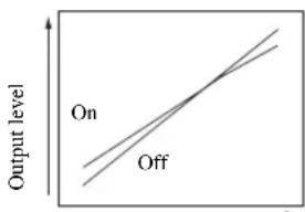
Automatic volume level adjustment (UniVolume)
While watching the TV, compensate the excessive volume differences to make it easier to hear during the following cases.
- When switching the channel
- When a TV program changed to commercial
- When one program is finished and another program started
Press NIVOLUME key to turn the function on/off. 6)
Volume balance adjustment
Use this feature to adjust the volume balance for each channel during playback. 7)
1
Press H LEVEL key.
2
Press 1 / key to select adjustable channel from the followings.
Left LV: Front left
Right LV: Front right
Center LV: Center
Sur.L Lv: Surround left
Sur.R Lv: Surround right
SWFR Lv: Subwoofer
When My Surround is selected:
CenterLv: Center
SurLR Lv: Surround left and right
SWFR LV: Subwoofer
3
Press key to adjust the volume.8
Adjustable range: -10.0 dB to +10.0 dB
4
Press H LEVEL key to exit from the menu.

- The default setting is "On" for DOCK input, and "Off" for other inputs.
- Compressed Music Enhancer does not work when the source is following digital audio signal,
Dolby TrueHD, DTS-HD Master Audio, etc. - Signal that sampling rate is more than 48kHz

The default setting is "Off".
- To set the UniVolume to "Off", press IVOLUME key.
- We recommend turning off the UniVolume function during playback of music.

Refer to "Volume level of each channel with test tones (r ^p. 37 ) when adjusting the test sound.

Example of volume balance
- If you have problems hearing words: Select Center Lv (center) to increase the level.
- When the sound does not seem like surround sound: Select Sur.L LV (surround left) and Sur.R LV (surround right) to increase the level.
The volume of subwoofer also can be adjusted by using SUBWOOFER +/- key.
Enjoying realistic surround sound (CINEMA DSP)
Playback surround sounds using Yamaha's exclusive CINEMA DSP.
1 Press SURROUND key to switch to surround mode.
2 Press the desired CINEMA DSP key repeatedly. 2)3
The CINEMA DSP category name appears in the front panel display and the CINEMA DSP indicator (p. 47) lights up.
MOVIE
Sci-Fi
This program clearly reproduces dialogs and special sound effects of the latest science fiction films and lets you feel a broad and expansive cinematic space.
Adventure
This program reproduces the thrilling environment of the latest action films and lets you feel the dynamic and excitement of fast-moving scenes.
Spectacle
This program reproduces the wide and grand environment and lets you have added impressions on spectacular scenes with strong visual impacts.
1)
CINEMA DSP
This unit is equipped with a Yamaha CINEMA DSP (digital sound field processing) chip containing several sound field programs used to enhance your playback experience. Most of the CINEMA DSP programs are precise digital recreations of actual acoustic environments of famous concert halls, music venues, and movie theaters.
2)
The CINEMA DSP programs are not available in the following conditions.
- HD audio signals are being played back on a Blu-ray disc.
- Audio signals with sampling frequency of higher than 96kHz are being played back.
- When using My Surround function (w.p. 23).
- When playing back in stereo mode.
3)
This unit automatically memorizes the settings assigned to each input source. When you select another input, the unit automatically recalls the last settings for the selected input.
MUSIC
Music Video
This program produces a vibrant environment and lets you feel as if you are at an actual jazz or rock concert.
Concert Hall
This program creates a rich surround effect of a large round concert hall with a great deal of presence, emphasizing the extension of sounds, and lets you feel as if you are seated close to the center of the stage.
Jazz Club
This program recreates the acoustic environment of "The Bottom Line", a famous jazz club in New York once and lets you feel as if you are seated right in front of the stage.
ENTERTAINMENT
Sports
This program reproduces the energetic environment of live sports broadcasting, converging a commentator's voice on the center and broadening the overall atmosphere of the stadium, and lets you feel as if you are scated at an actual stadium or a ball park.
Talk Show
This program reproduces excitement of live talk shows. It enhances the ambience of gaiety while keeping the conversations at a comfortable volume.
Drama
This program stables reverberations that match a wide range of movie genres from serious dramas to musicals and comedies, and offers an optimum 3D feeling, reproducing effects tones and background music softly but cubically around clear words.
Game
This program is suitable for role-playing and adventure games. It utilizes the sound field effects for movies to represent the depth and spatial feeling of the field during play, while offering movie-like surround effects in the movie scenes in the game.
Mch Stereo
This program downmixes multi-channel source to 2 channels and then outputs the sound from all speakers and produces stereo sounds in wide range. It is ideal for background music at parties, etc.
OFF (DSP Off)
Sur.Decorder (surround decoder)
This program plays back surround sound without CINEMA DISP sound field effect.
Changing the audio output method for surround playback
You can set the number of beam output channels and audio output method.
1 Press ⑤SETUP key.
Use / key and ENTER key to select "Sound Setup".
3 Use / key and ENTER key to select "Sound Out".
Use / key and ENTER key to select "Ch Out".
5 Press key to select the number of output channels.
Selectable item: 5.1ch, 7.1ch, Auto ch*4)
6 Press key to select "Sur."
7 Press key to select the desired audio output method. 5)
Selectable item:
(When 5.1ch is selected) 5Beam, St+3Beam, 3Beam, My Sur.
(When 7.1ch is selected) 5Beam+2, St+3Beam2, 3Beam, My Sur.
8 To exit the menu, press SETUP key.
Continued to the next page.

4)=5)
The default settings are marked with **.
- When "Auto ch"(automatic) is set.
When the input signal is 2ch / 5ch 5.1ch output
When the input signal is 6.1 / 7.1ch 7.1ch output
"Headphone" is displayed when headphones are connected, and the setting is cannot be changed.
■ Selectable item for "Sur. (surround)"
| Beam modes for "5.1ch" Beam modes for "7.1ch" | |||
| For enjoying surround sound effects on the movie, etc. to the fullest | 5 Beam (5 Beam)Outputs sound beams from the front right and left, center, and surround right and left channels. | 5Beam+2 (5Beam Plus2)Outputs sound beams from the front right and left, center, and surround back right and left channels. Surround right and left channel sources are mixed into the front right and left and surround back right and left channels. | |
| For watching live recordings on a Blue-ray disc | St+3Beam (Stereo+3Beam)Outputs normal sound from the front right and left channels and sound beams from the center and surround right and left channels. | St+3Beam2 (St+3Beam Plus2)Outputs normal sound from the front right and left channels and sound beams from the center and surround back right and left channels. Surround right and left channel sounds are output by using front right and left channel sound and surround back right and left sound beams. | |
| For enjoying movies with the whole family, or when the listening position is close to the backside of the wall. | 3 Beam (3 Beam)Outputs sound beams from the front right and left and center channels. Other channel sources are mixed into the front right and left channels. | ||
| For small listening area or when surround sound effects are insubstantial due to the listening room conditions. | My Sur. (My Surround)For the full effect of My Surround, your listening position must face toward the front of this unit. Even surround sound effects are insubstantial with other setting, you can enjoy sound with surround effects. | ||
Surround decoder setting
When this unit plays back 2-channel or 5.1-channel sources in surround mode, surround decoder enables them playback for 7.1-channel. You can enjoy a variety of surround sound effects by switching the decoder.
Select and set "Sur.Dec.Mode" in the option menu.
Refer to "Configuring settings for each input source (Option menu)" on page 27 for the operation of option menu.
Available decoders and recommended sources 2ch 5ch
| Decoder | Recommended source | |
| Pro Logic (Dolby Pro Logic) | - All sources | |
| PLII (Dolby Pro Logic II) | Movie | Movies |
| Music | Music | |
| Game | Games | |
| Neo:6 (DTS Neo:6) Cinema | Music | Movies |
| Music | ||
2ch→7ch
| Decoder | Recommended source | |
| PLI× (Dolby Pro Logic II×) | Movie | Movies |
| Music | Music | |
| Game | Games | |
| Neo:6 (DTS Neo:6) Cinema | Movies | |
| Music | ||
1)
About the surround decoder Playing back 5.1-channel sources
When "Ch Out" (channel output) is set to "7.1ch", this unit decodes 5.1-channel sources and then playback them in up to 7.1-channel surround (p.23). One of the following decoders is automatically selected depending on the input signals.
| 5.1ch input source Decoder | |
| PCM, Dolby Digital, Dolby Digital EX, Dolby TrueHD, Dolby Digital Plus | Dolby Pro Logic IIx Movie/Music |
| DTS Digital, DTS-ES matrix, DTS-HD Master Audio, DTS-HD High Resolution Audio | DTS-ES matrix |
| DTS-ES discrete DTS-ES discrete | |
2)
The decoders are available only when surround playback is selected. Available decoders vary depending on the "Ch Out" setting (carp. 24).
During stereo playback (cp.21) or using My Surround function (cp.23), surround decoder is invalid.
Using useful features
Listening with headphones
Insert a headphone plug to the PHONES jack (p. 46) of this unit.
The surround sound using headphones
With newly-developed 7.1 ch headphone surround technology, you can enjoy surround and stereo sound using headphones same as speaker. (p.21) When using headphones, changing CINEMA DSP (p.22) is also available.
1) ⏜ =
- The headphone volume, tone control, and LFE level can be set separately with speaker setting.
- If too much bass is heard while playing back 5.1 or 7.1 channels containing LFE channel (0.1ch), it may be improved by decreasing the LFE level. (p. 36)
Sleep timer/auto power down function
Use this feature to automatically set this unit to the standby mode after a specified period of time.
Press 5LEEP key repeatedly.
Switching the time it takes to switch to standby mode. The SLEEP indicator (p. 47) flashes in the front panel display. The SLEEP indicator in the front panel display lights up and the sleep timer is set.
Selectable item: Sleep 120 min., Sleep 90 min., Sleep 60 min., Sleep 30 min., AutoPowerDown, Off
■Auto power down function 3)
When AutoPowerDown is set, the unit is turned to standby mode automatically after 10 minutes from the selected input source is turned off or in standby mode. This function is useful to prevent you from forgetting to turn off the unit.
Settings for each input source (Option menu)
Set according to each input (TV/HDMI1-3/INPUT1-3/DOCK). Available menu items vary depending on the selected input.
Press input key (D, E) to select the input you want to change the setting.
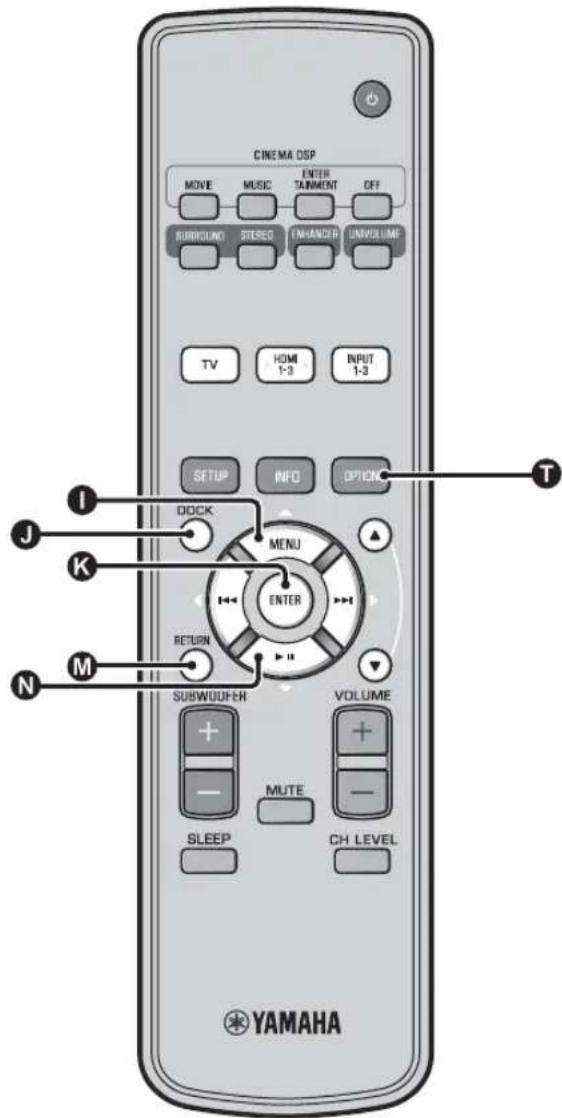
2 Press OPTION key.
The option menu is displayed on the front panel display.
Volume Trim
3 Select the items by pressing / key, then press ENTER key.
4 Change setting value by pressing L key.
5 To exit the option menu, press OPTION key.
Option menu items
The following menu items are provided for each input.
| Input source | Menu items |
| HDM11-3 Volume Trim, Decoder Mode, Sur. Dec. Mode, Signal Info | |
| TV | |
| INPUT1-3 | |
| DOCK | Volume Trim, Sur. Dec. Mode, Connect, Disconnect, Pairing, Interlock4) |
The option menu items are listed below. These settings are applied to the currently selected input source. The default settings are marked with **.
Adjusting input level of each jack (Volume Trim)
Adjust the input level for each jack to compensate for variations in volume between different input devices.
Adjustable range: -6.0 dB to 0.0 dB* to +6.0 dB
Switching the audio signal to play back (Decoder Mode)
Use to select digital audio signals for playback.
Selectable item: Auto*, DTS
Auto: This unit automatically selects the audio signal for playback. Normally select this mode.
DTS: This unit plays back only DTS signal.
Setting the surround decoder (Sur. Dec. Mode)
Refer to "Enjoying sound with your preference" (p. 21) for details.

The sleep timer setting is canceled if this unit is set to the standby mode or "Off" is selected.
- When AutoPowerDown is set, SLEEP indicator does not light up while the input source component is turned on.

-
If the unit is operated during the 10 minutes before entering standby mode, the unit does not enter standby mode until 10 minutes after the latest operation.
-
AutoPowerDown cannot be selected when:
-analog (INPUT3) or DOCK is selected.
- TV or HDM11-3 is selected and HDM1 control function is on.

For details on Interlock, refer to "Playing back iPod/iPhone (p. 29)". For details on Connect, Disconnect and Pairing, refer to "Playing back Bluetooth components (p. 30)".
■Displaying the input signal information (Signal Info)
Press 1 /N key to change the following information.
| Format Digital audio format | |
| Channel The number of channels included in input signal (front/surround/LFE (low frequency sound effects)) Display example: [3/2/0.1] → Front 3ch. Surround 2ch, LFE for input signal 1) | |
| Sampling Sampling frequency for digital input signal | |
| Bitrate Bitrate per second of input signal | |
| HDMI In HDMI video signal resolution | |
| HDMI Message When error occurs with HDMI (displayed only when error is occurred.) |

If the input signal includes channels that cannot be displayed in the format shown in the display example, the total number of channels will be displayed, as in "5.1ch".
Playing back iPod/iPhone
You can play music stored in iPod/iPhone connected to Yamaha Universal Dock for iPod (optional YDS-12, etc.) or Wireless System for iPod/iPhone (optional YID-W10).
1 Insert the iPod/iPhone into the Yamaha Universal Dock for iPod or Wireless System for iPod/iPhone connected to the DOCK terminal. 2)
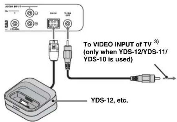
Place it as far as possible from this unit to avoid the noise.
2 Playback iPod/iPhone by selecting dock input by pressing OCK key. 4)
When using Yamaha Universal Dock for iPod (optional YDS-12, etc.) 5)
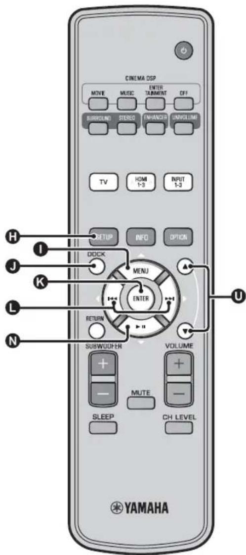
After setting the iPod/iPhone to the dock, you can use the remote control of this unit for playback operations. You can also display iPod/iPhone video on the TV.
1KLN:Controls iPod's menu.
0 : Controls click wheel.
iPod/iPhone supported by Universal Dock for iPod (YDS-12/YDS-11/YDS-10):
(As of September 2010)
- iPod touch, iPod mini, iPod (4th and 5th generations), iPod Classic, iPod nano, iPhone, iPhone 3G, iPhone 3GS
- iPhones are not compatible with YDS-11/YDS-10.
When using Wireless System for iPod (optional YID-W10) 6)
After connecting the receiver to this unit and setting the iPod/ iPhone to the transmitter, you can use the connected iPod/iPhone as a remote control while playing back music.
iPod/iPhone supported by Wireless System for iPod (YID-W10):
(As of September 2010)
iPod touch, iPod (5th generation), iPod Classic, iPod nano,
iPhone, iPhone 3G, iPhone 3GS
■Link with this unit (Interlock mode) 7)
When using YID-W10, You can use functions following for iPod/ iPhone when "Interlock" is set to "On" in option menu (p. 27).
- When playback starts on iPod/iPhone, this unit is turned on and DOCK (iPod) is selected as source automatically.
- This unit turns to standby mode automatically when the playback is stopped or after a while iPod/iPhone is removed from the transmitter.

- Connect when this unit is in standby mode.
- For details on how to connect and set up the YDS-12 and YID-W10, refer to manuals supplied with them.

When using YDS-12, YDS-11, or YDS-10 with the video pin cable (supplied) to connect theVIDEO OUT jack of this unit to theVIDEO INPUT jack of the TV, you can display iPod/Phone video on the TV.

- Some features may not be available depending on the model or the software version of your iPod/Phone.
- For details about the messages displayed on the front panel display of connected iPod/iPhone, refer to "iPod/iPhone (v.p. 44)" in "Troubleshooting".
- Be sure to set the volume to minimum before docking or removing your iPod/iPhone.

This unit charges the battery of an iPod/iPhone stationed in the Yamaha Universal Dock for iPod connected to the DOCK terminal even when this unit is in standby mode. "Charging" appears in the front panel display.

- When YID-W10 is connected, and the "Interlock" is set to "On", it charges even in standby mode.
- To set the playback volume higher than the maximum volume of the iPod/iPhone, use this unit's remote control to control the volume.

This function works with ring tone and sound of application. When the iPhone is set to silent mode, this unit does not turn on with the ring tone.
Playing back Bluetooth components
Play back music stored in the Bluetooth components (portable audio players, Bluetooth-enabled computers, etc.) connected to the Bluetooth Wireless Audio Receiver (optional YBA-10).
Pairing
About "Pairing"
It is the operation of registering a component for communications. Pairing must be performed before using a Bluetooth component with the Yamaha Bluetooth Wireless Audio Receiver connected to the system for the first time, or if the registered pairing data has been deleted. To ensure security, a time limit of 8 minutes is set for the pairing operation. Please read and fully understand all the instructions before starting.
1 As described in step 1 (p. 29) of "Playing back iPod/iPhone", connect the Bluetooth Wireless Audio Receiver (optional YBA-10) to DOCK terminal.
2 Press DOCK key to set the input to DOCK.
3 Turn on the Bluetooth component you want to pair with, and then enter pairing state. 2)
4 Press OPTION key.
Option menu for DOCK input appears in the display.
5 Select "Pairing" by pressing 0 / N key and press ENTER key. 3)
"Searching..." appears on the display when the Bluetooth connection is initiated.
6 Check that the Bluetooth components recognize the Bluetooth Wireless Audio Receiver.
If the Bluetooth component detects the Yamaha Bluetooth wireless audio receiver, the audio receiver name ("YBA-10 YAMAHA", for example) appears in the device list of the Bluetooth component.
7 Select the Bluetooth Wireless Audio Receiver from the component list of the Bluetooth components and input "0000" for password of the Bluetooth.
Connecting 4)
Press DOCK key to set the input to DOCK.
2 Press OPTION key.
3 Select "Connect" and press ENTER key. 5)
4 To disconnect the Bluetooth Wireless Audio Receiver from the Bluetooth component, press OPTION key again to display option menu, select "Disconnect", and press ENTER key.
1)
For details, refer to the manual supplied with YBA-10.
2)
Refer to the manual of your Bluetooth component for details.
3)
To cancel pairing, press RETURN key.
4)
When establishing the Bluetooth connection from this unit, it is only possible to connect to the most recently connected Bluetooth component.
5)
- For details of messages, refer to "Bluetooth (a8 p. 45)" in "Troubleshooting".
- If you want to establish a connection with a Bluetooth other than the one most recently connected, initiate the connection from that Bluetooth component. Refer to the manual of your Bluetooth component for details.
Setup menu
Setting procedure
Before performing following procedures, check if this unit and TV are connected with the video pin cable (supplied) and switch TV input to "VIDEO INPUT 1 (example)".
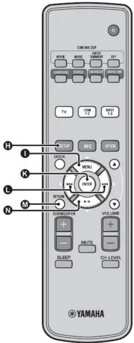
1 Press SETUP key to enter the setup menu. 1)
SET MENU
*MEMORY
-
AUTO SETUP
-
MANUAL SETUP
SOUND SETUP INPUT MENU
- DISPLAY MENU
[▲]/[▼]:Up/Down
2 Select menu by pressing 1 / key and press ENTER key.
Repeat these step to display desired menu.
MANUAL SETUP
-1) SETTING PARAMETERS
2)BEAM ADJUSTMENT
3) IMAGE LOCATION
[▲]/[▼]:Up/Down
3 Change setting value of each menu by pressing L key.
4 Press SETUP key again to exit the setup menu.
Press RETURN key to return to the previous menu.
Setup menu list
| Category Menu Sub menu Features Page | ||||
| MEMORY LOAD Memory 1, Memory 2, SAVE Memory 1, Memory 2, Memory 3 | Memory 3 | Loads the beam and sound settings saved in the memory. | #sp. 17 | |
| Saves the current beam and sound settings to the memory. | #sp. 16 | |||
| AUTO SETUP BEAM-SOUND OPTIMIZE | AUTO SETUP Optimizes the beam and sound settings automatically. | #sp. 14 | ||
| Optimizes the beam settings automatically. | #sp. 14 | |||
| Optimizes the sound settings automatically. | #sp. 14 | |||
| MANUAL SETUP SETTING PARAMETERS | INSTALLED POSITION, listening room settings, distance settings | Adjusts the listening room and listening position settings. #p. 34 | ||
| BEAM ADJUSTMENT | HORIZONTAL ANGLE, BEAM TRAVEL LENGTH, FOCAL LENGTH (Front L, Front R, Center, Surround L, Surround R) | Adjusts the various sound beam settings. | #p. 35 | |
| IMAGE LOCATION | LEFT, RIGHT | Adjusts the sound position of the front right and left channels. | #p. 36 | |
| SOUND SETUP | TONE CONTROL | TREBLE, BASS | Adjusts the output level of high-frequency or low-frequency sound. | #p. 36 |
| SUBWOOFER | LFE LEVEL | Configures the subwoofer settings. | #p. 36 | |
| AUDIO DELAY | AUTO LIP SYNC | Adjusts delay in output timing between video signals and audio signals. | #p. 36 | |
| TV, HDMI1-3, INPUT1, INPUT2, INPUT3 | Adjusts output timing of audio signals manually. | #p. 36 | ||
| Dynamic Range Control | Adaptive DRC, Dolby/ DTS DRC | Adjusts the dynamic range. | #p. 37 | |
| CHANNEL LEVEL | Front L, Front R, Center, Surround L, Surround R, Subwoofer | Adjusts the volume of each channel. | #p. 37 | |
| SOUND OUT | CHANNEL OUT | Configs the sound beam output settings. | #p. 37 | |
| SURROUND | Configs the surround audio signal output settings. | #p. 37 | ||
| INPUT MENU INPUT | ASSIGNMENT | OPTICAL1, OPTICAL2, COAXIAL, ANALOG | Assigns jacks according to the component to be used. | #p. 38 |
| AUDIO SELECT (HDMI1, HDMI2, HDMI3) | Configs the sound output from HDMI jack | #p. 38 | ||
| INPUT RENAME | TV, INPUT1, INPUT2, INPUT3, HDMI1, HDMI2, HDMI3 | Renames the displayed input source. | #p. 39 | |
| HDMI SETUP | HDMI CONTROL, SUPPORT AUDIO | Configs the HDMI settings. | #p. 39 | |
| DISPLAY MENU | F. DISPLAY SETUP | STANDARD DIMMER, AUTO DIMMER | Configs the front panel display settings. | #p. 40 |
| OSD SETUP | OSD SHIFT, OSD BACK COLOR | Configs the OSD settings. | #p. 40 | |
| LANGUAGE SETUP | ENGLISH, DEUTSCH, FRANÇAIS, ESPÁNOL, ITALIANO, NEDERLANDS, PYCCKHN, SVENSKA | Changes the language used in the OSD. | #p. 40 | |
| UNIT SETUP | METERS, FEET | Changes the display unit of measurement. | #p. 40 | |
Manual setup
Use this menu to manually adjust the parameters related to the sound beam output. To fine-adjust parameters configured by AUTO SETUP, use "BEAM ADJUSTMENT" and "IMAGE LOCATION".
Setting parameters
MANUAL SETUP SETTING PARAMETERS
Use to set the position of this unit in your listening room and the distance of this unit from the listening position. 1)2
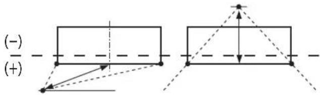
1 In "SETTING PARAMETERS 1/3", configure "INSTALLED POSITION".
Select the installed position of this unit.3)
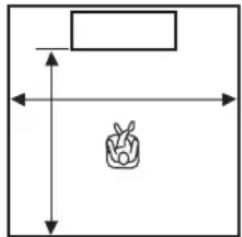
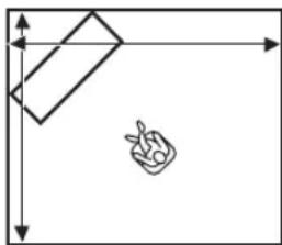
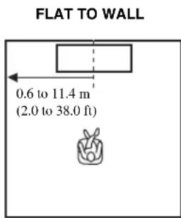
Selectable item: FLAT TO WALL* (parallel to wall), ANGLE TO WALL OR CORNER (angle to wall or corner)

FLAT TO WALL ANGLE TO WALL OR CORNER

2 In "SETTING PARAMETERS 2/3", configure the listening room settings.
Specify the length and width of the listening room. Control range: 2.0m to 12.0m (6.5 ft to 40.0
When this unit is installed parallel to wall, specify the width of the listening room and the distance between this unit and rear wall.
When this unit is installed at the corner of the room, specify the width of length of the listening room.
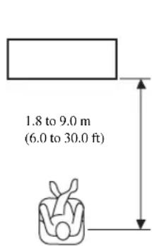
3 In "SETTING PARAMETERS 3/3", configure the distance settings.
Specify the distance between the listening position and this unit. When this unit is installed parallel to wall, you also need to specify the distance between the listening position and left wall.
Control range (from this unit): 1.8m to 9.0m (6.0 ft to 30.0 ft)
Control range (from left wall): 0.6m to 11.4m (2.0 ft to 38.0 ft)
1)
If you make adjustments in "SETTING PARAMETERS", the "BEAM ADJUSTMENT" parameters are automatically adjusted.
2)
If you make adjustments in "SETTING PARAMETERS", the beam optimization settings made in the AUTO SETUP procedure will be lost.
3)
If you change this setting, "Surround mode" setting changes automatically (15p. 23).
Beam adjustment
MANUAL SETUP BEAM ADJUSTMENT
Use to manually adjust the various sound beam settings.4)
1 Configure "HORIZONTAL ANGLE".
Adjust the horizontal angle of sound beams for each channel using test tones.
Adjust toward L (left) to move the direction of the output to the left and adjust toward R (right) to move it to the right.
Control range: L90° to R90°
2 Configure "BEAM TRAVEL LENGTH". 5)
Adjust the distance that sound beams travel after being output and reflected off the wall until they arrive at the listening position so that all sounds can arrive at the listening position at the same time.
Control range: 0.3m to 24.0m (1.0 ft to 80.0 ft)
The length of each arrow indicates the beam travel length.
Adjust the distance from the front of this unit to the focal point of output for each channel to achieve an expansive feeling for each channel. Adjust toward - (minus) to move the focus outward (widen the sweet spot) and adjust toward + (plus) to move the focus toward the normal position (narrow the sweet spot).
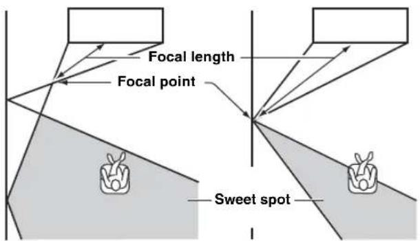
We recommend that you use the initial setting
(-0.5 m or -1.5 ft) for "Center".
Sub menu: Front L, Front R, Surround L, Surround R
Control range: -1.0 m to +13.0 m (-3.5 ft to +43.5 ft)
Sub menu: Center
Control range: -1.0 m to -0.5 m* to +13.0 m (-3.5 ft
to -1.5 ft* to +43.5 ft)
Example
Front left channel Center channel


4) 一 ^ - 5 ) Note
- The "BEAM ADJUSTMENT" parameters are automatically adjusted (except "Center" in "FOCAL LENGTH") if you run the AUTO SETUP (p. 12) or if you configure "SETTING PARAMETERS" (p. 34).
Depending on the surround mode settings (p. 23), some channel positions may not be available for selection. In this case, "--" is displayed.
#
Configure this setting only when you have adjusted "HORIZONTAL ANGLE".
6)
The width of the sweet spot becomes slightly wider than the width of this unit if you run the AUTO SETUP (cp. 12) or if you configure "SETTING PARAMETERS" (cp. 34).
Image location
MANUAL SETUP IMAGE LOCATION
Use to adjust the direction from which the front left and right channel sound is heard so that each sound can be heard closer to the center channel.
Use this feature to redirect audio signals if the sound coming from the front left and right channels seems unnatural.
You can adjust this parameter only when "5BeamPlus2", "5 Beam" or "3 Beam" is selected in "Surround mode" (p. 23). Select "ON" to configure the sound direction.
Selectable item: OFF*, ON
1 Adjust the image location for the front left channel (LEFT).
The higher the percentage, the louder the output from the center.
Control range: 0% to 95%
Without adjustment With the front left
channel adjusted
2 Adjust the image location for the front right channel (RIGHT).
The higher the percentage, the louder the output from the center.
Control range: 0% to 95%
Without adjustment With the front right
channel adjusted
Tone control
Tone control
SOUND SETUP TONE CONTROL
Use to adjust the output level of high/low-frequency sound. Sub menu: TREBLE (High tone), BASS (Low tone)
Adjustable range: -10.0 dB to 0.0 dB* to +10.0 dB
Subwoofer settings
SOUND SETUP SUBWOOFER
Sub menu: LFE LEVEL
Adjust the volume of Dolby Digital and DTS signals included in the LFE (low frequency sound effects). 2)
Adjustable range: -20.0 dB to 0.0 dB*
Audio delay control
SOUND SETUP AUDIO DELAY
Flat panel display TV images sometimes lag behind the sound.
You can use this function to delay the sound output to
synchronize it with the video image.
Sub menu: AUTO LIP SYNC
Select how to automatically adjust the audio output delay.
Selectable item: ON*, OFF
"ON": The audio output delay is automatically adjusted. This item is available when a TV that supports the automatic lipsync is connected to the HDMI OUT (ARC) jack of this unit.
"OFF": Select "OFF" if the TV connected to the HDMI OUT (ARC) jack of this unit does not support the automatic lipsync or you want to disable the automatic lipsync. The delay time for each input can be adjusted manually by following items.
Sub menu: TV
Adjust the audio output delay applied to signals input from the TV jacks.
Adjustable range: 0 ms* to 300 ms
1)2)
To adjust the volume of each channel, see "CHANNEL LEVEL"
(p. 37)
What is LFE?
"LFE" refers to low frequency effects included in the digital audio
Digital signals such as Dolby Digital and DTS include a dedicated line for LFE.
Sub menu: HDMI1-3
Manually adjust the audio output delay applied to signals input from the HDMI IN jacks. This setting is effective only when "AUTO LIP SYNC" is set to "OFF".
Adjustable range: 0 ms to 30 ms* to 300 ms
Sub menu: INPUT1/INPUT2/INPUT3
Adjust the audio output delay applied to signals input from the INPUT1/INPUT2/INPUT3 jacks.
Adjustable range: 0 ms to 30 ms* to 300 ms
Dynamic range control
SOUND SETUP Dynamic Range Control
Use to adjust the dynamic range compression. Dynamic range is the difference between the smallest sound that can be heard above the noise of the equipment and the biggest sound that can be heard without distortion.
Sub menu: Adaptive DRC 3)
Select whether to automatically adjust the dynamic range in conjunction with the volume level. When this function is set to "ON", the dynamic range is adjusted as follows.
When the volume level is low:
Narrow the dynamic range. Loud sound is played back softer, and soft sound which is hard to be listened to is played back louder.
When the volume level is high:
Widen the dynamic range. From soft sound to loud sound, source sound is played back without adjusting volume.
Input level Input level
Volume:low Volume:high
Selectable item: ON*, OFF
"ON": Adjust dynamic range automatically. 4)
"OFF": The dynamic range is not adjusted automatically.
Sub menu: Dolby/DTS DRC
Select the amount of dynamic range applied when this unit is decoding Dolby Digital and DTS signals.
Selectable items: Min/Auto, Standard, Max*
Max: Outputs sound without adjusting the dynamic range of the input signals. 5)
Standard: The dynamic range recommended for regular home use.
Min/Auto:
(Minimum) Adjust the dynamic range for low volume or a quiet environment, such as at night, for playing back bitstream signals except for Dolby TrueHD signals.
(Auto) Adjust the dynamic range based on information from the input signal when playing back Dolby TrueHD signal.
Volume level of each channel with test tones
SOUND SETUP CHANNEL LEVEL
Use to adjust the volume of each channel with test tones. 6)
Sub menu:
Front L, Front R, Center, Surround L, Surround R, Subwoofer
Adjustable range: -10.0 dB to +10.0 dB
Sound out setting
Sound beam output configuration
SOUND SETUP SOUND OUT
Sub menu: CHANNEL OUT, SURROUND
Use to configure the number of output channels (5.1ch/7.1ch/ Auto) or audio output method. For details, see "Changing the audio output method for surround playback" (pp. 23).

- When set to "ON", "Dolby/DTS DRC" is automatically set to "Max".
- This setting is not available when the UniVolume is set to "ON".

This makes the sound easier to hear when listening at low volume at night, for example.

"Adaptive DRC" is automatically set to "OFF" when the settings other than "Max" is selected.

When using My Surround function, Center, Surround L/R, Subwoofer can be selected.
Input assignment
Input assignment
INPUT MENU INPUT ASSIGNMENT 1)
Use to change the key assignments of input jacks on this unit. The sound of the input select is decided according to key assign set to each jacks. 2)
Selectable item:
| Sub menu | Default setting |
| Audio input jack | |
| OPTICAL1 TV | |
| DIGITAL (OPTICAL) TV | |
| OPTICAL2 INPUT1 | |
| DIGITAL (OPTICAL)1 | |
| COAXIAL INPUT2 | |
| DIGITAL (COAXIAL)2 | |
| ANALOG INPUT3 | |
| AUDIO INPUT 3 |
Selectable item: TV, INPUT1, INPUT2, INPUT3, HDMI1, HDMI2, HDMI3
AUDIO SELECT (Audio select of HDMI input)
Switch the HDMI sound signal to Off when you want to playback the video from HDMI IN jack and sound from AUDIO INPUT jack. 3)
Sub menu: HDMI1, HDMI2, HDMI3
Selectable item: OFF, ON*
1)
Set corresponding HDMI IN to "OFF" in audio input setting to HDMI IN jack of "INPUT ASSIGNMENT" when selecting HDMI IN.
2)
The selectable item for other digital sound input jack already selected will not be displayed.
3)
Example: When connecting this unit and PC
1 Connect DVI output jack of the PC and HDMI IN 3 using DVI HDMI converter cable.
2 Connect a sound output jack of the PC and AUDIO INPUT 3 jack (ANALOG).
3 Set "ANALOG" of "INPUT ASSIGNMENT" to "HDM13"
4 Set "HDMI3" of "AUDIO SELECT (INPUT ASSIGNMENT)" to "OFF".
Input rename
INPUT MENU INPUT RENAME
Use to change the name of the input source displayed when the input source is selected. Select a name from templates, or enter an original name.
■Selecting a name from templates
1 Press 0 /N key to select the input source to be renamed.
2 Press key to select a input source name.
Selectable item: Blu-ray, DVD, DVR, CATV, Satellite, Game
3 To exit the menu, press RETURN key.
■Entering an original name
1 Press / key to select the input source to be renamed.
2 Press ENTER key.
"▼" appears above the new name display to indicate the position to be entered.
3 Press key to place the (underscore) under the space or the character you want to edit.
4 Press 1 / N key to select the desired character.
5 Repeat steps 3 and 4 to edit other characters.
6 To complete the setting, press ENTER key.
7 To exit from the menu, press RETURN key.
HDMI setup
Menu:HDMI SETUP
Use to configure the settings related to HDMI signals and HDMI control function.
■HDMI control
Sub menu: HDMI CONTROL
Use this function to link this unit and an HDMI control-compatible TV via HDMI. For details, see "Operating the unit by TV's remote control (p. 18)".
Selectable item: OFF*, ON
"OFF": Disable the control function. The standby power consumption of this unit decreases.
"ON": Enable the control function.
Audio playback component
Sub menu: SUPPORT AUDIO
Use to select a component to play back HDMI audio signals. This setting is effective when "HDMI CONTROL" is set to "OFF".5)
Selectable item: YRS-2100 (YRS-1100\* ,OTHER
"YRS-2100 (YRS-1100): Play back the input sound signal. "OTHER": Play back the equipment connected to HDMI OUT (ARC) jack.

A to Z, 0 to 9, a to z, and symbols (!,?,<,>,etc.) are available for input.

HDMI video signals input to one of the HDMI IN jacks of this unit are always output from the HDMI OUT (ARC) jack of this unit.
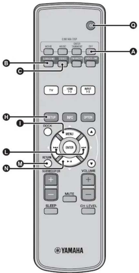
DISPLAY MENU
■Front panel display setup
DISPLAY MENU F.DISPLAY SETUP
Use to adjust the brightness and display settings of the front panel display.
Sub menu: STANDARD DIMMER
Use to adjust the brightness of the front panel display when you operate this unit. The front panel display dims as the number becomes small.
Selectable item: -2, -1, OFF* (brightest)
Sub menu: AUTO DIMMER
Use to adjust the brightness of the front panel display at normal time (unit/remote control without operation) based on setting value of the "STANDARD DIMMER". The front panel display dims as the number becomes small.
Selectable item: DISPLAY OFF (hide), -3, -2, -1, OFF* (brightest)
OSD setup
DISPLAY MENU OSD SETUP
Use to adjust the display position and select the background color of the OSD.
Sub menu: OSD SHIFT
Use to adjust the vertical position of the OSD. Adjust toward the - (minus) direction to raise the position of the OSD, and adjust toward the + (plus) direction to lower it.
Selectable item: -5 to ± 0^ to +5
Sub menu: OSD BACK COLOR
Use to select the background color of the OSD.
Selectable item: Blue*, Gray, Black, Purple, Red
■Language setup 1)
DISPLAY MENU LANGUAGE SETUP
Use to select the language used in the OSD.
Selectable item: ENGLISH* (English), DEUTSCH (German), FRANÇAIS (French), ESPÁNOL (Spanish), ITALIANO (Italian), NEDERLANDS (Dutch), PYCCKM (Russian), SVENSKA (Swedish)
■Unit Setup
DISPLAY MENU UNIT SETUP
Use to change the display unit of measurement.
Selectable item: METERS, FEET
For Canada model, "FEET" is default setting. For other models, "METERS" is default setting
- Select METERS to enter distances in meters.
- Select FEET to enter distances in feet.
1)
Press and hold SETUP key to display the menu directly.
Advanced setup
1 Press okey to turn this unit to standby mode.
2 While holding down INPUT key on the front panel, press key on the remote control to turn on the power.
"ADVANCED SETUP" appears in the front panel display.
3 Release INPUT key on the front panel.
4 Press / to select the desired menu on the front panel display and then press ENTER key. 1)
5 Change setting by pressing / key. 2)
6 Press key to set this unit to the standby mode.
The new setting will be reflected when you turn on the unit by pring key.
| Menu Description | Selectable item/ Adjustable range | |
| TURN ON VOLUME Sets volume level at power-on. Off* (Not set), 01 to 99, MAX (Maximum) | ||
| MAX VOLUME SET Sets maximum volume. 01 to 99, MAX* (Maximum) | ||
| PANEL INP. KEY | Enables/disables the INPUT key on the front panel. | P.INPUT: ON* (Enabled), P.INPUT:OFF (Disabled) |
| F.PANEL. KEY | Enables/disables the keys on the front panel. | P.INPUT: ON* (Enabled), P.INPUT:OFF (Disabled) |
| R(INPUT POWER Enables/disables power-on by remote control input keys when the unit is in standby mode. | R(INPUT PW: OFF* (Disables power-on), R(INPUT PW: ON (Enables power-on) | |
| AC ON STANDBY | Sets whether or not this unit returns to its previous state when AC power is restored after a temporary power loss. | AC STANDBY: OFF* (Restores the state before power was lost), AC STANDBY: ON (Enters standby mode) |
| MEMORY PROTECT | Prohibits saving of the settings by using the memory setting function ( \( ^{18} \)p. 16). | PROTECT:OFF* (Protect is not performed), PROTECT:ON (Protect is performed) |
| DEMO MODE | Demonstrates sound beam. 3) | BEAM DEMO:OFF* (Normal playback), BEAM DEMO:ON (Demo mode) |
| FACTORY PRESET Resets all settings to their default values, except settings in ADVANCED SETUP. | PRST:CANCEL* (Reset is not performed), PRST: RESET (Reset is performed) | |
1)
To return to the previous menu, press RETURN key.
2)
The default settings are marked with **.
3)
This unit outputs sound beam down-mixed to 1 channel moving horizontally to right and left. By this function, you can feel how sound beam is output from this unit.
"Demo" appears in the front panel display while setting demo mode.
Start/stop moving horizontally
Press A Off key.
Auto Demo On: Sound beam automatically moves horizontally to right and left
Auto Demo Off: The direction of sound beam is fixed
Adjust the angle of sound beam manually
Press SURROUND/STEREO key in the state of "Auto Demo Off"
Troubleshooting
Troubleshooting
Refer to the chart below when this unit does not function properly. If the problem you are experiencing is not listed below or if the instruction below does not help, set this unit to the standby mode, disconnect the AC power supply cable, and contact the nearest authorized Yamaha dealer or service center.
General
| Problem Cause Remedy | See page | ||
| This unit does not operate properly. | The internal microcomputer has been frozen by an external electric shock (such as lightning or excessive static electricity) or by a power supply with low voltage. | Set this unit to the standby mode, disconnect the AC power supply cable, plug it back in after 30 seconds, and use it normally. | - |
| This unit fails to turn on when key is pressed, or enters the standby mode soon after the power has been turned on. | The AC power supply cable is not firmly connected to the AC wall outlet. | Connect the AC power supply cable firmly to the AC wall outlet. | 8 |
| This unit has been exposed to a strong external electric shock (such as lightning and strong static electricity). | Set this unit to the standby mode, disconnect the AC power supply cable, plug it back in after 30 seconds, and use it normally. | - | |
| This unit suddenly enters the standby mode. | The internal temperature becomes too high and the overheat protection circuitry has been activated. | Wait for about one hour for this unit to cool down and turn it back on. | - |
| The sleep timer has turned the unit off. Turn on the power and play back the source again. 27 | |||
| The power has shut down after wireless was disconnected for a while during “Interlock” is set to “On” using YID-W10. | Resume wireless connection or detect audio of iPod/iPhone and turn on the unit. | - | |
| No sound. | Incorrect input or output cable connections. Connect them with an HDMI connection or a digital connection. | 8,9 | |
| No appropriate input source has been selected. | Select an appropriate input source with INPUT key or input selector keys. | 20 | |
| The volume is turned down. Turn up the volume. 20 | |||
| The sound is muted. Press MUTE or VOLUME +/- key to resume audio output and adjust the volume level. | 20 | ||
| There is input signal cannot be played back by this unit. | Play a source whose signals can be reproduced by this unit. Change the system settings of the source component. | - | |
| “SUPPORT AUDIO” is set to “OTHER”. Set to “YRS-2100 (YRS-1100)”. 39 | |||
| “HDMI CONTROL” is set to “OFF”. When connecting ARC (Audio Return Channel) supported TV and this unit using HDMI cable only, set “HDMI CONTROL” to “ON”. | 39 | ||
| Connect coaxial digital input jack and TV's audio output jack using a digital audio pin cable. | 9 | ||
| Headphones are connected to this unit. | |||
| The sound of effect channel for cable broadcasting may become noise. | The source has a surround effect. | Do not put surround effect by this unit. | - |
| No sound or too small sound from a specific channel. | The output level of the channel is muted. | Raise the output level of the channel. | 21,37 |
| The beam setting is inappropriate. | Adjust the beam setting. | 23 | |
| You play back the source in the stereo mode. | Start surround playback. | 22 | |
| Some audio output methods do not output sound beams for certain channels. | Adjust the beam setting. | 23 | |
| Surround sound effects are insubstantial. | When connecting this unit with playback component and TV digitally, the output setting of the playback component and TV is not valid. | Refer to the manual supplied with your component and check the setting. | - |
| The listening room is not a regular shape, or the unit or listening position is not at the center of the right and left wall of the listening room. | Relocate the unit or listening position. | 6, 34 | |
| There is no wall in the path of the sound beam. | Try placing a flat object, such as a board, in the path of the sound beam. | - | |
| When My Surround is selected, listening position is not in front of the unit. | Listen in front of this unit. | 24 | |
| No sound from the internal subwoofer. | The source does not contain low bass signals. | ||
| The level of subwoofer is low. Increase the subwoofer level with SUBWOOFER + key. | 20 | ||
| The image is not displayed on TV screen. | HDMI cable is not securely connected. Connect them with an HDMI connection or a digital connection. | 8, 9 | |
| Menu screen of this unit is not displayed. | VIDEO OUTPUT jacks of this unit and TV are not connected. | Connect the jacks with video pin cable (supplied). | 8 |
| The input switch of TV is not set correctly. Switch the input source for your TV. - | |||
| A digital or high-frequency equipment produces noises. | The unit may be placed close to digital equipment or high-frequency equipment. | Leave these equipments from the unit. | - |
| The system settings change automatically. | When "HDMI CONTROL" is set to "ON", operations of the TV (for example, changing channels, etc.) may change the system settings, such as the surround mode. | Set "HDMI CONTROL" to "OFF" or set the system again by using its remote control. | 39 |
| The HDMI control function does not work properly. | "HDMI CONTROL" is set to "OFF". Set "HDMI CONTROL" to "ON". 39 | ||
| The HDMI control function is disabled on your TV. | Refer to the manual supplied with your TV and check the setting. | - | |
| The number of the connected HDMI components is over the limit. | Disconnect some of the HDMI components. | - | |
| The automatic lipsync is not effective even "AUTO LIP SYNC" is set to "ON". | The TV does not support the automatic lipsync. | Set "AUTO LIP SYNC" to "OFF" and then manually adjust the audio output delay. | 36 |
| "Not Available" appears on the front panel display after key operation. | The key is unable to function in the current condition. | ||
Remote control
| Problem Cause Remedy | See page | |
| The remote control does not work and/or function properly. | Wrong distance or angle. The remote control functions within a maximum range of 6 m (20 ft) and no more than 30 degrees off-axis from the front panel. | 7 |
| Direct sunlight or lighting (from an inverter type of fluorescent lamp, etc.) is striking the remote control sensor of this unit. | - | |
| The batteries are weak. Replace all batteries. 7 | ||
iPod/iPhone

If the problem occur other than the following message displayed on the display, check the connection of your iPod/iPhone.
| Message Features Remedy | See page | ||
| Connect error | iPod/iPhone has a problem with communication. | Turn off the power of this unit and reconnectYamaha Universal Dock for iPod again. | 29 |
| Reset iPod/iPhone to a Yamaha Universal Dock for iPod. | 29 | ||
| Low Battery | The battery of iPod/iPhone is running low. | ||
| Unknown iPod | The iPod/iPhone being used is not supported by this unit. | Connect supported iPod to this unit. | 29 |
| Connected | iPod/iPhone is correctly connected to the Yamaha Universal Dock for iPod. | ||
| iPod/iPhone is correctly set to Yamaha Wireless Transmitter and connected to this unit wirelessly. | |||
| Disconnected | iPod/iPhone is removed from Yamaha Universal Dock for iPod. | ||
| The wireless connection of this unit and iPod/iPhone is disconnected. | |||
| Unable to play | For some reason, iPod/iPhone cannot be played back. | Check whether the music stored in iPod/iPhone is playable or not. | - |
| Charging | Your iPod/iPhone is charging. | ||
Bluetooth
Note
If the problem occur other than the following message displayed on the display, check the connection of your Bluetooth component.
| Message Features Remedy | See page | |
| Searching... | The Yamaha Bluetooth Wireless Audio Receiver (such as YBA-10, optional) and the Bluetooth component are in the process of the pairing. | |
| The Yamaha Bluetooth Wireless Audio Receiver (such as YBA-10, optional) and the Bluetooth component are in the process of establishing the connection. | ||
| Completed | The pairing is completed. | |
| Canceled | The pairing is canceled. | |
| Not Available | The Yamaha Bluetooth Wireless Audio Receiver (such as YBA-10, optional) and the Bluetooth component are in the process of the pairing. | |
| Connected | The connection between the Yamaha Bluetooth Wireless Audio Receiver (such as YBA-10, optional) and the Bluetooth component is established. | |
| Disconnected | The Bluetooth component is disconnected from the Yamaha Bluetooth Wireless Audio Receiver (such as YBA-10, optional). | |
| Not found | The unit cannot find the Bluetooth component while performing the pairing or trying to connect to the Bluetooth component. | (When pairing) - The pairing should be performed for this unit and the Bluetooth component at the same time. Make sure that the Bluetooth component is also a pairing mode. (When Connected) - Make sure that the power of the Bluetooth component is on. - Check if the distance between the Yamaha Bluetooth Wireless Audio Receiver and the Bluetooth component is in 10 meters. |
| - The Bluetooth component and this unit have not been performed pairing. Pairing the stations again. | ||

- Resetting this unit
When the unit freezes, the problem may solve by resetting the unit.
To reset the unit, press key of this unit for more than 10 seconds.
Controls and functions
Controls and functions
Front panel
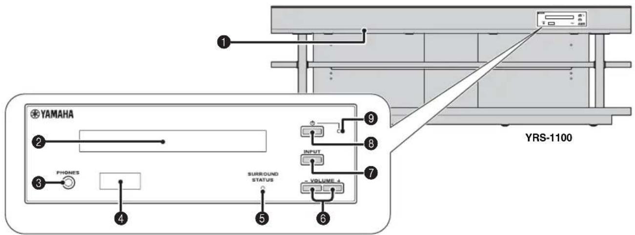
1 INTELLIBEAM MIC jack
Connect the supplied IntelliBeam microphone for AUTO SETUP (p. 11).
2 Front panel display
Shows information about the operational status of this unit. (p. 47)
3 PHONES jack
For connecting headphones. (w.p. 26)
Remote control sensor
Receives infrared signals from the remote control. (p. 48)
SURROUND STATUS indicator
Lights up according to the input signal.
| Displayed color | Input signal |
| Blue Following surround | round audio signal formats: Dolby TrueHD, Dolby Digital Plus, DTS-HD Master Audio, DTS-HD High Resolution, Multi-channel Linear PCM |
| Orange Surround audio | signal other than above |
| Off Audio signal other | ter than above or no signal |
6 VOLUME +/-key
Controls the volume of the unit. (p. 20)
7 INPUT key
Selects playback component. (w-p. 9)
8 key
Turns on the unit or set it to the standby mode.
Note
In the standby mode, this unit consumes a small amount of power in order to receive infrared signals from the remote control or to search for HDMI signals.
System indicator
Lights up to show the system condition.
| Light Power | HDMI CONTROL (×p. 39) | Interlock Mode (×p. 29) |
| Green On - | ||
| Red Standby | On Off | |
| Standby Off | ||
| Off Standby | Off Off |
Rear panel
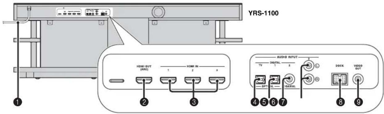
Power cable
For connecting to an AC wall outlet. (p. 8)
HDMI OUT (ARC) jack
For connecting HDMI compatible TV and external components. (p. 8)
3 HDMI IN jack
For connecting HDMI compatible Blu-ray disc player, tuner and game console. (p. 8, 9)
OPTICAL digital input (TV) jack
For connecting optical cable to the TV. (p. 8)
OPTICAL digital input 1 jack
For connecting optical cable to the external components. (p. 9)
COAXIAL digital input 2 jack
For connecting digital audio pin cable to the external components. (u3p.9)
7 AUDIO INPUT 3 jack
For connecting analog cable to the external components. (p. 9)
DOCK terminal
For connecting optional Yamaha Universal Dock for iPod, Wireless System for iPod/iPhone, and Bluetooth Wireless Audio Receiver. (p. 29, 30)
VIDEO OUT jack
For connecting video input jack of TV to play back video in iPod/ iPhone. (p. 8)
Front panel display
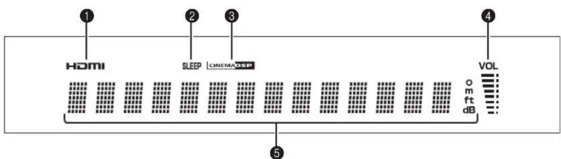
HDMI indicator
Lights up when HDMI signal is input.
SLEEP indicator
Lights up when the sleep timer is set. (p. 27)
CINEMA DSP indicator
Lights up when a sound field program is selected (p. 22).
4 VOL indicator
Indicates the current volume level. (p. 20)
Multi information display
Displays information in alpha-numeric values.
Displays playback components and current sound output when power is on.
Remote control
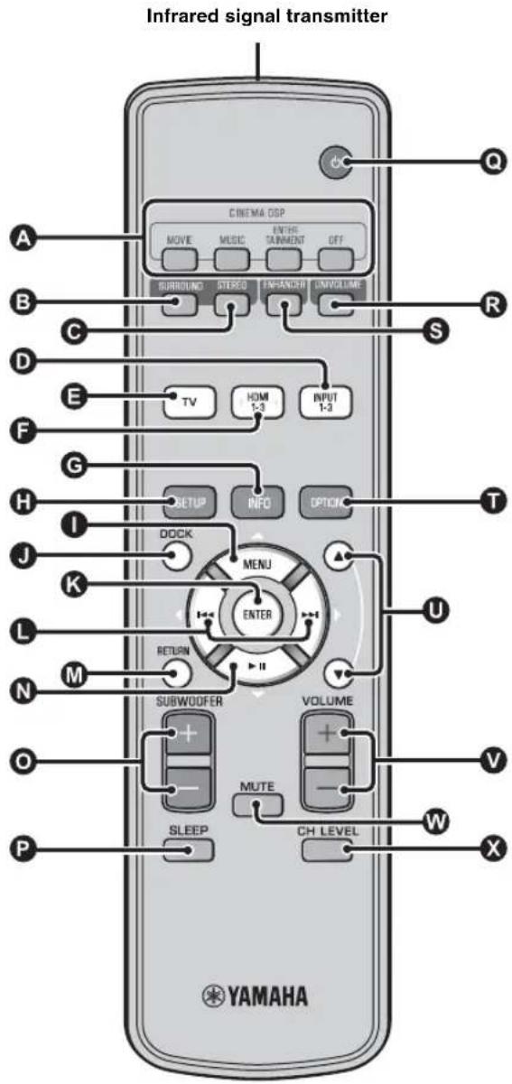
CINEMA DSP program keys
Select the CINEMA DSP programs (p. 22).
Switches to surround playback. (p. 22)
STEREO key
Switches to stereo playback. (E, p. 21)
D E F Input selector keys
Select playback component. (vS p. 20)
6 INFO key
Switches the information display on the front panel as follows.
-
Input/Output: Input name/surround mode
-
DSP Program: Sound field program of CINEMA DSP (only when using CINEMA DSP)
-
Audio Decoder: Sound signal decoder currently selected
H SETUP key
Displays the setup menu. (p. 32)
K L N MENU (△) key, ENTER key, () key, () key, () key
-
Change the setting. (w,p. 32)
-
Operate iPod.
DOCKkey
Selects iPod/iPhone or Bluetooth component. (p. 29, 30)
RETURN key
Returns to the previous menu screen.
SUBWOOFER (+ / - ) key
Adjusts the volume balance of subwoofer.
SLEEP key
Sets the sleep timer. (v.p. 27)
@ key
Turns on the unit or set it to the standby mode. (p. 20)
UNIVOLUME key
Turns UniVolume mode to on/off. (p. 21)
ENHANCER key
Turns Compressed Music Enhancer to on/off. (p. 21)
OPTION key
Displays option menu for each input source. (p. 27)
0 ▲/key
Operate iPod wheel. (p. 29).
VOLUME (+ / - ) key
Controls the volume of the unit. (p. 20)
W MUTE key
Mute/resume the sound. (p. 20)
CH LEVEL key
Adjusts the volume balance during playback. (p. 21)
Glossary
Digital Sound Projector
Ordinarily, two front speakers, a center speaker, two surround speakers, and a subwoofer are necessary for enjoying 5.1 channel surround sound.

Typical 5.1 channel speaker system
7.1 channel surround playback
This unit creates surround sound by reflecting projected sound beams off the walls of your listening room.
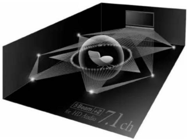
The sound image of the system
Sampling frequency
The number of sampling (process for digitalizing analog signals) per second. In principle, the higher the sampling rate, the wider the frequency range that can be played back, and the higher the quantized bit rate, the finer the sound that can be reproduced.
Channel (ch)
A channel is an audio type that has been divided based on range and other characteristics.
Ex. 7.1 channel
- Front speakers, Left (1ch), Right (1ch)
- Center speaker (1ch)
- Surround speakers, Left (1ch), Right (1ch)
- Surround back speakers, Left (1ch), Right (1ch)
- Subwoofer (1ch × 0.1* = 0.1ch)
- In contrast to a full 1-channel band, a component designed to enhance low frequency sound for added effect.
Dolby Digital
Digital surround sound system which is developed by Dolby Laboratories provides completely independent multi-channel audio. With 3 front channels (left, center, and right) and 2 surround stereo channels, Dolby Digital provides five full-range audio channels. By using 2 channel stereo for the surround speakers, more accurate moving sound effects and surround sound environment are possible than with Dolby Surround.
Dolby Digital Plus
Dolby Digital Plus is an advanced audio technology developed for high-definition programming and media including HD broadcasts, and Blu-ray Disc. Selected as an optional audio standard for Blu-ray Disc, this technology delivers multichannel sound with discrete channel output. Supporting bitrates up to 6.0 Mbps, Dolby Digital Plus can carry up to 7.1 discreet audio channels simultaneously. Supported by HDMI and designed for the optical disc players and AV receivers/amplifiers of the future, Dolby Digital Plus also remains fully compatible with the existing multichannel audio systems that incorporate Dolby Digital.
Dolby Pro Logic IIx
Dolby Pro Logic IIx is a new technology enabling discrete multichannel playback from 2-channel or multi-channel sources. There are three modes available: "Music mode" for music sources, "Movie mode" for movie sources (for 2-channel sources only) and "Game mode" for game sources.
Dolby TrueHD
Dolby TrueHD is an advanced lossless audio technology developed for high-definition disc-based media including Blu-ray Disc. Selected as an optional audio standard for Blu-ray Disc, this technology delivers sound that is bit-for-bit identical to the studio master, offering a high-definition home theater experience. Supporting bitrates up to 18.0 Mbps, Dolby TrueHD can carry up to 8 discrete channels of 24-bit/96 kHz audio simultaneously. Dolby TrueHD also remains fully compatible with the existing multichannel audio systems and retains the metadata capability of Dolby Digital, allowing dialog normalization and dynamic range control.
Deep Color
Deep Color is a type of video signal that can be transmitted by the HDMI jacks of this unit. Deep Color refers to the use of various color depths in displays, up from the 24-bit depths in previous versions of the HDMI specification. This extra bit depth allows HDTVs and other displays go from millions of colors to billions of colors and eliminate on-screen color banding for smooth tonal transitions and subtle gradations between colors. The increased contrast ratio can represent many times more shades of gray between black and white. Also Deep Color increases the number of available colors within the boundaries defined by the RGB or YCbCr color space.
DTS
Digital surround sound system developed by DTS, Inc., which provides 5.1 channel audio. With an abundance of audio data, it is able to provide authentic-sounding effects.
DTS-HD High Resolution Audio
DTS-HD High Resolution Audio is a high resolution audio technology developed for high-definition disc-based media including Blu-ray Disc. Selected as an optional audio standard for Blu-ray Disc, this technology delivers sound that is virtually indistinguishable from the original, offering a high-definition home theater experience. Supporting bitrates up to 6.0 Mbps for Blu-ray Disc, DTS-HD High Resolution Audio can carry up to 7.1 discrete channels of 24-bit/96 kHz audio simultaneously.
DTS-HD Master Audio
The lossless high quality audio format created for next generation optical disc such as Blu-lay Disc. It is selected as an audio standard for Blu-ray Disc. Supporting bitrates up to 24.5 Mbps for Blu-ray Disc, DTS-HD High Master Audio can carry up to 7.1 discrete channels of 24-bit/96 kHz audio simultaneously.
HDMI
HDMI (High-Definition Multimedia Interface) is the first industry supported, uncompressed, all-digital audio/video interface. When used in combination with HDCP (High-bandwidth Digital Content Protection), HDMI provides a secure audio/video interface that meets the security requirements of content providers and system operators.
PCM (Pulse Code Modulation)
Linear PCM is a signal format under which an analog audio signal is digitized, recorded, and transmitted without using any compression. This is used as a method of recording CDs and DVD audio. The PCM system uses a technique for sampling the size of the analog signal per very small unit of time. Standing for pulse code modulation, the analog signal is encoded as pulses and then modulated for recording.
x.v.Color
x.v. color is a type of video signal that can be transmitted by the HDMI jacks of this unit. It is a more extensive color space than sRGB, and allows the expression of colors that could not be expressed before. While remaining compatible with the color gamut of sRGB standards, "x.v.Color" expands the color space and can thus produce more vivid, natural images. It is particularly effective for still pictures and computer graphics.
Specifications
Amplifier section
Rated Output Power
Front L/R (1 kHz, 1% THD, 6 Ω) 45 W + 45 W
Small dia. speaker (1 kHz, 1% THD, 4 Ω) 27.2 W
Subwoofer (100 Hz, 1% THD, 3 Ω) 90 W
Maximum Output Power
Front L/R (1 kHz, 10% THD, 6 Ω) 50 W + 50 W
Small dia. speaker (1 kHz, 10% THD, 4 Ω) 32 W
Subwoofer (100 Hz, 10% THD, 3 Ω) 100 W
Speaker section
- Small dia. speaker. 2.8 cm (1-1/8 in) magnetic shielding cone
- Front speaker
- 6 × 10 cm (2-3/8 × 3-7/8 in) non-magnetic shielding cone
- Subwoofer
- 13 cm (5-1/8 in) non-magnetic shielding cone
Input Jack
Audio Input Optical 2 (TV, INPUT 1) Coaxial. 1 (INPUT 2) Analog 1 pair (INPUT 3)
HDMI Input 3 (HDMI IN 1 to 3)
Output Jacks
- HDMI Output
- Video Output (Composite video, 1.0 Vp-p)
- [Canada, and Korea models]
- [Other models]
- Headphone
- Headphone Output Power (1 kHz, 460 mV input, 16 Ω)
- 220 mV
General
Power Supply [Canada model] AC 120 V, 60 Hz [Europe, U.K., Korea and Asia models] AC 220-240 V, 50/60 Hz
Power Consumption 42 W
- Standby Power Consumption (HDMI Control on) ....... Less than 5.0 W (HDMI Control off) ....... Less than 0.5 W
Frequency Response. 35 Hz to 20 kHz
Dimensions (W× H× D) YRS-1100. 1200× 500× 445mm (47-1/4 × 19-3/4 × 17-5/8 in) YRS-2100. 1600× 500× 445mm (63 × 19-3/4 × 17-5/8 in)
Weight YRS-1100. 46.5 kg (102.5 lbs) YRS-2100. 63 kg (138.9 lbs)
- Specifications are subject to change without notice.
Intel/Beam
The "Integern Intellibeam" are trademarks of Yamaha Corporation.
CINEMADSP
The "Cinema DSP" are registered trademarks of Yamaha Corporation.

Manufactured under license from Cambridge Mechatronics Ltd. Worldwide patents applied for. The "Logo and Digital Sound ProjectorTM" are trademarks of Cambridge Mechatronics Ltd.
DOLBY. TRUHE
Manufactured under license from Dolby Laboratories. "Dolby", "Pro Logic" and the double-D symbol are trademarks of Dolby Laboratories.

dtts-HD
Manufactured under license under U.S. Patent #s: 5,451,942; 5,956,674; 5,974,380; 5,978,762; 6,226,616; 6,487,535; 7,212,872; 7,333,929; 7,392,195; 7,272,567 & other U.S. and worldwide patents issued & pending. DTS, DTS-HD and the Symbol are registered trademarks, & DTS-HD Master Audio, and the DTS logos are trademarks of DTS, Inc. Product includes software. © DTS, Inc. All Rights Reserved.
iPod, iPhone
"iPod' is a trademark of Apple Inc., registered in the U.S. and other countries. "iPhone" is a trademark of Apple Inc.
Bluetooth
Bluetooth is a registered trademark of Bluetooth SIG and is used by Yamaha in accordance with a license agreement.
HOMI
"HDMI," the "HDMI" logo and "High-Definition Multimedia Interface" are trademarks, or registered trademarks of HDMI Licensing LLC.
x.v.Color
"x.v.Color" is a trademark of Sony Corporation.
Univolume
"UniVolume" is a trademark of Yamaha Corporation.
Available signal information
HDMI signal compatibility
Receivable audio signals
| Audio signal types Audio signal format Compatibility media | |
| 2ch Linear PCM 2ch, 32-192 kHz, 16/20/24 bit CD, DVD-Video, DVD-Audio, etc. | |
| Multi-ch Linear PCM 8ch, 32-192 kHz, 16/20/24 bit DVD-Audio, Blu-ray disc, HD DVD, etc. | |
| Bitsstream (SD Audio) Dolby Digital, Dolby Digital EX, DTS, DTS-ES | DVD-Video, etc. |
| Bitsstream (HD Audio) Dolby TrueHD, Dolby Digital Plus, DTS-HDMAster Audio, DTS-HD High Resolution Audio | Blu-ray disc, HD DVD |

Refer to the supplied instruction manuals of the input source component, and set the component appropriately.
- When CPPM copy-protected DVD-Audio is played back, video and audio signals may not be output depending on the type of the DVD player.
This unit is not compatible with HDCP-incompatible HDMI or DVI components. Refer to the supplied instruction manuals of HDMI or DVI components for HDCP compatibility.
To decode audio bitstream signals on this unit, set the input source component appropriately so that the component outputs the bitstream audio signals directly (does not decode the bitstream signals on the component). Refer to the supplied instruction manuals for details.
■Repeatable video signals 1)
- This unit is compatible with the video signals of the following resolutions:
480i / 60Hz
720p / 60Hz ,50Hz
- 576i/50 Hz
· 1080i / 60Hz,50Hz
· 480p / 60Hz
· 1080p / 60Hz 50Hz 24Hz
- 576p/50 Hz
- D e e p C o l o r
-x.v.Color
-3D video signal
Digital audio signal (optical/coaxial)
| Audio signal types Audio signal format Compatible media | |
| 2ch Linear PCM 2ch, 32-96 kHz, 16/20/24 bit CD, DVD-Video, DVD-Audio, etc. | |
| Bitstream Dolby Digital, Dolby Digital EX, DTS, DTS-ES | DVD-Video, etc. |

The compatible video signal is changed depending on the connected TV.
Using the supplied demonstration DVD
By playing back the supplied demonstration DVD, you can check the digital signals being input properly from the Blu-ray disc player through the digital connection (HDMI, optical, or coaxial) and experience this unit's multi-channel surround sound.
Playing back the demonstration DVD
1 Select input sources both on this unit and your TV so that audio signal of DVD is input to this unit and video signal is input to your TV.
HDMI connection: On your TV, select this unit as the input source. On this unit, select the Blu-ray disc player as the input source.
Audio/Video connection: Select the Blu-ray disc player as the input source on both of your TV and this unit.
2 Load the demonstration DVD.
3 Select "Rain and Thunder" from the DVD menu.
Display the DVD menu screen by using the remote control of the Blu-ray disc player and then playback "Rain and Thunder".
4 Press OPTION key on the remote control to display the option menu.
Press / key to select "Signal Info", and then press ENTER key.
6 Check that "Dolby D" appears in the front panel display.
Dolby D
If the "Dolby D" does not appear, the digital audio signal of the demonstration DVD is not input to this unit. Check the connections and settings of the Blu-ray disc player.
7 Press key and check that "3/2/0.1" appears in the front panel display.
3/2/0.1
Note
"Dolby D" does not appear when the Blu-ray disc player is not playing back the demonstration DVD and the DVD menu screen is displayed.
Experience the Dolby Digital 5.1ch surround sound.
The sound of rain and buzzing of cicadas are heard from all around the listening position.

Enjoy the surround sound in surround playback mode (es'p. 21).
If "Dolby D" does not appear
If "Dolby D" does not appear in the front panel display in step 6, check the followings.
Is the Blu-ray disc player connected to this unit using a digital cable?
You need to connect these components with digital cables (HDMI cable, optical cable, or coaxial cable) to playback 5.1-channel contents such as Dolby Digital.
Is an input source selected correctly on this unit?
Check that which input jack of this unit the Blu-ray disc player is connected to. Then check whether the name of input source displayed in the front panel display of this unit is the same as that of the input jack used.

If you connect the Blu-ray disc player to the HDMI IN 1 jack, when you select HDMI 1 as the input source, "HDMI 1" should be displayed.
Is digital audio output set correctly on the Blu-ray disc player?
HDMI connection: Set the digital audio output setting to "Auto" or "Bitstream".
Digital audio connection: Enable "Dolby Digital/DTS" or "Bitstream".

Refer to the owner's manual supplied with the Blu-ray disc player for the settings.
Numerics
2ch 25
2-channel 25
3 Beam (3 Beam) 24
5 Beam (5 Beam). 24
5.1ch 23,24,25
5Beam+2 (5Beam Plus2) 24
7.1ch 23,24
A
Adaptive DRC 37
Advanced setup 41
Analog audio stereo pin cable 9
Angle to wall or corner. 34
ARC 8
Audio output method 23
Audio select of HDMI input. 38
AUTO LIP SYNC 36
Auto power down function. 27
AUTO SETUP 15
AutoPowerDown 27
B
BEAM ADJUSTMENT 35
Beam optimization 11
BEAM OPTIMIZE ONLY. 14
BEAM TRAVEL LENGTH 35
BEAM+SOUND OPTIMIZE 14
Before installing this unit 5
Bluetooth components 30
Bluetooth Wireless Audio Receiver 30
Blu-ray disc player 20
C
Cardboard microphone stand. 11
Ch Out 23
Channel (ch) 49
Channel output 25
CINEMA DSP 22
CINEMA DSP indicator. 47
Compressed Music Enhancer 21
D
Decoder Mode 27
Deep Color. 50
Digital audio pin cable. 9
Digital Sound Projector 49
Dolby Digital 49
Dolby Digital Plus 49
Dolby Pro Logic IIx. 50
Dolby TrueHID 21,50
DTS. 27,50
DTS-HD High Resolution 46
DTS-HD High Resolution Audio 50
DTS-HD Master Audio 21,50
Dynamic range control. 37
E
Entertainment 23
Error buzzer sounds 13
Error message 13
F
F.DISPLAY SETUP 40
FOCAL LENGTH 35
Front panel. 46
Front panel display 47
G
Game console. 20
H
HD audio signals. 22
HDMI. 50
HDMI cable 8
HDMI control 39
HDMI control function 18
Headphone 23,26
HORIZONTAL ANGLE 35
1
IMAGE LOCATION 36
INPUT ASSIGNMENT 38
INPUT RENAME 39
INTELLIBEAM MIC jack 46
IntelliBeam microphone 11
Interior slide sheet. 5
Interlock 29
iPhone 29
iPod. 29
L
LANGUAGE SETUP 40
LFE 26,36
M
MEMORY 16
Movie 22
MP3 21
Music 23
My Sur. (My Surround) 24
0
Optical cable 8,9
Option menu 27
OSD SETUP 40
P
Pairing 30
Parallel to wall 34
PCM (Pulse Code Modulation) 50
PHONES jack 46
Power cable. 8,47
R
Rear panel 47
Registering HDMI components to TV 19
Remote control. 48
Remote control sensor 46
s
Sampling frequency 22,49
Sampling rate 21
Satellite/cable TV 9
SETTING PARAMETERS 34
Signal Info 28
SLEEP indicator 27,47
Sleep timer 27
Sound optimization. 11
Sound out setting 37
St+3Beam (Stereo+3Beam) 24
St+3Beam2 (St+3Beam Plus2) 24
STATUS indicator. 46
Stereo mode 21
Subwoofer 20,21
Subwoofer settings.. 36
SUPPORT AUDIO 39
Sur. 23
Sur.Dec.Mode. 27
Surround decoder 25
Surroundmode 21
Surround sound 22
Sweet spot 35
System indicator. 46
T
Tempered glass 5
Test tones 37
Tone control 36
TV 20
U
UNIT SETUP 40
UniVolume. 21
V
Video pin cable 8
VOL indicator 20,47
Volume. 20
Volume balance. 21
Volume Trim 27
W
Wireless System 29
WMA 21
X
x.v.Color. 50
Y
YBA-10. 31
YDS-12 29
YID-W10 29
Information for Users on Collection and Disposal of Old Equipment and Used Batteries

These symbols on the products, packaging, and/or accompanying documents mean that used electrical and electronic products and batteries should not be mixed with general household waste.
For proper treatment, recovery and recycling of old products and used batteries, please take them to applicable collection points, in accordance with your national legislation and the Directives 2002/96/EC and 2006/66/EC.

By disposing of these products and batteries correctly, you will help to save valuable resources and prevent any potential negative effects on human health and the environment which could otherwise arise from inappropriate waste handling.
For more information about collection and recycling of old products and batteries, please contact your local municipality, your waste disposal service or the point of sale where you purchased the items.

[Information on Disposal in other Countries outside the European Union]
These symbols are only valid in the European Union. If you wish to discard these items, please contact your local authorities or dealer and ask for the correct method of disposal.
Note for the battery symbol (bottom two symbol examples):
This symbol might be used in combination with a chemical symbol. In this case it complies with the requirement set by the Directive for the chemical involved.
Pb
CAUTION
RISK OF ELECTRIC SHOCK DO NOT OPEN

ATTENTION: POUR RÉDUIRE LES RISQUES D'INCENDIE ET DE DÉCHARGE ELECTRIQUE, NE PAS RETIRER LE COUVERCLE (OU LE PANNEAU ARRÊRIÈ). AUNCUE PIECE INTERNE NE PEUT ÉTRE CHANGES PAR L'UTILISATEUR. POUR L'ENTRETIEN, S'ADRESSER À UN PERSONNEL QUALIFIÉ.
Installation parallele
Installation parallele
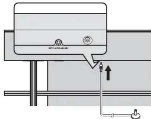
Microphone Intellibeam
1)÷(2)÷
6 Debranchez le microphone IntelliBeam.
Sur.Decorder (decodeur surround)
Important Notice: Guarantee Information for customers in EEA+ and Switzerland
English
For detailed guarantee information about this Yamaha product, and Pan-EEA* and Switzerland warranty service, please either visit the website address below (Printable file is available at our website) or contact the Yamaha representative office for your country. * EEA: European Economic Area
http://europe.yamaha.com/warranty/

YAMAHA
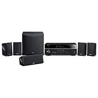
- IMPORTANT SAFETY INSTRUCTIONS
- CAUTION
- RISK OF ELECTRIC SHOCK DO NOT OPEN
- - Explanation of Graphical Symbols
- IMPORTANT
- FCC INFORMATION (for US customers)
- IMPORTANT NOTICE: DO NOT MODIFY THIS UNIT!
- CAUTION: READ THIS BEFORE OPERATING YOUR UNIT.
- WARNING
- Notes
- FOR CANADIAN CUSTOMERS
- ■For U.K. customers
- Note
- Special Instructions for U.K. Model
- Notes on remote controls and batteries
- We Want You Listening For A Lifetime
- Contents
- PREPARATION
- CONNECTION/INITIAL SETTINGS
- PLAYBACK
- SETTINGS
- TROUBLESHOOTING
- ABOUT THIS UNIT
- About this manual
- Getting started
- Supplied accessories
- Installation
- Notes on installation
- Caution: Handling the tempered glass
- Before installing this unit
- My Surround
- Installing this unit
- Parallel installation
- Corner installation
- ■Installation examples
- Ideal installation condition
- Installing in a non-square room
- Remote control preparation
- Installing the batteries
- Operation range
- TV and Blu-ray disc player connection
- HDMI cable (optional)
- HDMI cable (optional)
- Optical cable (supplied)
- Video pin cable (supplied)
- Audio return channel (ARC) supported TV
- What is audio return channel (ARC)?
- Game console or tuner connection
- Selecting language for menu display
- Auto setup for appropriate surround effects (IntelliBeam)
- Beam optimization:
- Sound optimization:
- Installling the IntelliBeam microphone
- Place the IntelliBeam microphone on a flat level surface at your normal listening position.
- ■Assembling the supplied cardboard microphone stand
- Check if a supplied video pin cable is connected and headphones are not connected.
- Using AUTO SETUP (IntelliBeam)
- Turn the unit and your TV on.
- Switch TV's input to "VIDEO INPUT 1 (example)".
- Connect the supplied IntelliBeam microphone to the INTELLIBEAM MIC jack.
- 1)=2)
- 3)
- AUTO SETUP
- Press ENTER key to start the AUTO SETUP procedure and then leave the room within 10 seconds.3)
- Press ENTER key to confirm the results. 5)
- AUTO SETUP COMPLETE
- Remove the IntelliBeam microphone.
- 4)÷5)÷
- 6)
- AUTO SETUP via setup menu
- Select Item:
- Connect the IntelliBeam microphone to this unit after "AUTO SETUP (PREPARATION & CHECK)" screen is displayed.
- ■Error messages for AUTO SETUP
- Saving several measurement results (Memory setting function)
- Saving settings
- 1) = 19
- ■Loading settings
- Operating the unit by TV's remote control
- What is the HDMI control function?
- 1)
- Setting the HDMI control function
- If the HDMI control function is not working
- Changing the connection method and connected components
- The example of TV settings
- Playback features
- Basic operation for playback
- To mute the sound
- Enjoying sound with your preference
- Switching stereo/surround sound
- Playing back digitally compressed formats (MP3, WMA, etc.) with enriched sound (Compressed Music Enhancer)
- Automatic volume level adjustment (UniVolume)
- Volume balance adjustment
- Example of volume balance
- Enjoying realistic surround sound (CINEMA DSP)
- MOVIE
- Sci-Fi
- Adventure
- Spectacle
- 1)
- CINEMA DSP
- 2)
- 3)
- MUSIC
- Music Video
- Concert Hall
- Jazz Club
- ENTERTAINMENT
- Sports
- Talk Show
- Drama
- Game
- Mch Stereo
- OFF (DSP Off)
- Sur.Decorder (surround decoder)
- Changing the audio output method for surround playback
- 4)=5)
- ■ Selectable item for "Sur. (surround)"
- Surround decoder setting
- Select and set "Sur.Dec.Mode" in the option menu.
- About the surround decoder Playing back 5.1-channel sources
- 2)
- Using useful features
- Listening with headphones
- The surround sound using headphones
- 1) ⏜ =
- Sleep timer/auto power down function
- Press 5LEEP key repeatedly.
- ■Auto power down function 3)
- Settings for each input source (Option menu)
- Option menu items
- Adjusting input level of each jack (Volume Trim)
- Switching the audio signal to play back (Decoder Mode)
- Setting the surround decoder (Sur. Dec. Mode)
- ■Displaying the input signal information (Signal Info)
- Playing back iPod/iPhone
- Playing back Bluetooth components
- Pairing
- About "Pairing"
- Connecting 4)
- 4)
- 5)
- Setup menu
- Setting procedure
- SET MENU
- MANUAL SETUP
- Setting parameters
- MANUAL SETUP → SETTING PARAMETERS
- In "SETTING PARAMETERS 1/3", configure "INSTALLED POSITION".
- In "SETTING PARAMETERS 2/3", configure the listening room settings.
- In "SETTING PARAMETERS 3/3", configure the distance settings.
- Beam adjustment
- MANUAL SETUP → BEAM ADJUSTMENT
- Configure "HORIZONTAL ANGLE".
- Configure "BEAM TRAVEL LENGTH". 5)
- 4) 一 ^ - 5 ) Note
- #
- Image location
- MANUAL SETUP → IMAGE LOCATION
- Adjust the image location for the front left channel (LEFT).
- Adjust the image location for the front right channel (RIGHT).
- Tone control
- SOUND SETUP → TONE CONTROL
- Subwoofer settings
- SOUND SETUP → SUBWOOFER
- Sub menu: LFE LEVEL
- Audio delay control
- SOUND SETUP → AUDIO DELAY
- Sub menu: AUTO LIP SYNC
- Selectable item: ON*, OFF
- Sub menu: TV
- 1)2)
- What is LFE?
- Sub menu: HDMI1-3
- Sub menu: INPUT1/INPUT2/INPUT3
- Dynamic range control
- SOUND SETUP → Dynamic Range Control
- Sub menu: Adaptive DRC 3)
- Volume:low Volume:high
- Sub menu: Dolby/DTS DRC
- Selectable items: Min/Auto, Standard, Max*
- Volume level of each channel with test tones
- SOUND SETUP → CHANNEL LEVEL
- Sub menu:
- Sound out setting
- Sound beam output configuration
- SOUND SETUP → SOUND OUT
- Input assignment
- INPUT MENU → INPUT ASSIGNMENT 1)
- AUDIO SELECT (Audio select of HDMI input)
- Example: When connecting this unit and PC
- Input rename
- INPUT MENU → INPUT RENAME
- ■Selecting a name from templates
- ■Entering an original name
- HDMI setup
- Menu:HDMI SETUP
- ■HDMI control
- Sub menu: HDMI CONTROL
- Selectable item: OFF*, ON
- Audio playback component
- Sub menu: SUPPORT AUDIO
- Selectable item: YRS-2100 (YRS-1100\* ,OTHER
- DISPLAY MENU
- ■Front panel display setup
- DISPLAY MENU → F.DISPLAY SETUP
- Sub menu: STANDARD DIMMER
- Selectable item: -2, -1, OFF* (brightest)
- Sub menu: AUTO DIMMER
- OSD setup
- DISPLAY MENU → OSD SETUP
- Sub menu: OSD SHIFT
- Selectable item: -5 to ± 0^ to +5
- Sub menu: OSD BACK COLOR
- ■Language setup 1)
- DISPLAY MENU → LANGUAGE SETUP
- ■Unit Setup
- DISPLAY MENU → UNIT SETUP
- Selectable item: METERS, FEET
- Advanced setup
- General
- iPod/iPhone
- Bluetooth
- - Resetting this unit
- Controls and functions
- Front panel
- INTELLIBEAM MIC jack
- Front panel display
- PHONES jack
- Remote control sensor
- SURROUND STATUS indicator
- VOLUME +/-key
- INPUT key
- key
- System indicator
- Rear panel
- Power cable
- HDMI OUT (ARC) jack
- HDMI IN jack
- OPTICAL digital input (TV) jack
- OPTICAL digital input 1 jack
- COAXIAL digital input 2 jack
- AUDIO INPUT 3 jack
- DOCK terminal
- VIDEO OUT jack
- Front panel display
- HDMI indicator
- SLEEP indicator
- CINEMA DSP indicator
- VOL indicator
- Multi information display
- Remote control
- CINEMA DSP program keys
- STEREO key
- D E F Input selector keys
- INFO key
- H SETUP key
- DOCKkey
- RETURN key
- SUBWOOFER (+ / - ) key
- SLEEP key
- @ key
- UNIVOLUME key
- ENHANCER key
- OPTION key
- ▲/key
- VOLUME (+ / - ) key
- W MUTE key
- CH LEVEL key
- Glossary
- Digital Sound Projector
- channel surround playback
- Sampling frequency
- Channel (ch)
- Dolby Digital
- Dolby Digital Plus
- Dolby Pro Logic IIx
- Dolby TrueHD
- Deep Color
- DTS
- DTS-HD High Resolution Audio
- DTS-HD Master Audio
- HDMI
- PCM (Pulse Code Modulation)
- x.v.Color
- Specifications
- Amplifier section
- Speaker section
- Input Jack
- Output Jacks
- Intel/Beam
- CINEMADSP
- DOLBY. TRUHE
- dtts-HD
- iPod, iPhone
- HOMI
- Univolume
- Available signal information
- HDMI signal compatibility
- Receivable audio signals
- ■Repeatable video signals 1)
- Digital audio signal (optical/coaxial)
- Using the supplied demonstration DVD
- Playing back the demonstration DVD
- Experience the Dolby Digital 5.1ch surround sound.
- If "Dolby D" does not appear
- Is the Blu-ray disc player connected to this unit using a digital cable?
- Is an input source selected correctly on this unit?
- Is digital audio output set correctly on the Blu-ray disc player?
- Numerics
- A
- B
- C
- D
- E
- F
- G
- H
- 1
- L
- M
- 0
- P
- R
- s
- T
- U
- V
- W
- X
- Y
- Information for Users on Collection and Disposal of Old Equipment and Used Batteries
- [Information on Disposal in other Countries outside the European Union]
- Note for the battery symbol (bottom two symbol examples):
- Installation parallele
- 1)÷(2)÷
- Debranchez le microphone IntelliBeam.
- Sur.Decorder (decodeur surround)
- Important Notice: Guarantee Information for customers in EEA+ and Switzerland
- YAMAHA
Brand : YAMAHA
Model : YRS1100
Category : Home theater audio system