AVIC505 - GPS Navigation System PIONEER - Free user manual and instructions
Find the device manual for free AVIC505 PIONEER in PDF.

| Product type | GPS navigation system for automobile |
| Brand | Pioneer |
| Model | AVIC-505 |
| Dimensions (main unit) | Approx. 200 x 150 x 50 mm |
| Weight (main unit) | Approx. 500 g |
| Power supply | 12 V DC, vehicle battery with negative ground |
| Power consumption | Approx. 10 W |
| Main functions | GPS navigation, voice guidance, route calculation, speed detection, reverse signal input, voice control, color display |
| GPS antenna | Magnetic mount, 5 m cable, indoor or outdoor installation |
| Microphone | Wired microphone for voice control, installation on sun visor or steering column |
| Remote control | Infrared remote control with alkaline batteries UM-4/LR03 (2 x 1.5 V) |
| Maintenance and cleaning | Wipe with a soft, dry cloth. Do not use liquids or abrasive cleaners. |
| Safety | Do not install yourself (risk of short circuit). Have installation done by a professional. Do not use while driving if it distracts. |
| Spare parts and repairability | 6 A fuse, batteries, GPS antenna, microphone, remote control, power cable, mounting brackets. Repair by an authorized Pioneer service. |
| General information | Use only as a driving aid. Do not use for emergency services. Follow traffic rules. |
Frequently Asked Questions - AVIC505 PIONEER
User questions about AVIC505 PIONEER
0 question about this device. Answer the ones you know or ask your own.
Ask a new question about this device
Download the instructions for your GPS Navigation System in PDF format for free! Find your manual AVIC505 - PIONEER and take your electronic device back in hand. On this page are published all the documents necessary for the use of your device. AVIC505 by PIONEER.
USER MANUAL AVIC505 PIONEER
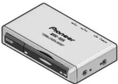
natural_image
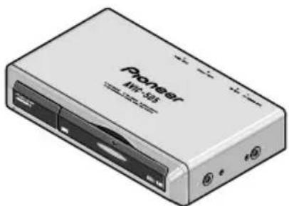
Illustration of a Pioneer AVIC-505 audio device with remote control and two USB devices (no text or symbols on main body)Pioneer
ABOUT YOUR NEW MOBILE NAVIGATION SYSTEM AND THIS MANUAL.....
- The Pioneer Mobile Navigation System is intended solely as an aid to you in the operation of your vehicle. It is not a substitute for your attentiveness, judgement and care while driving.
- Do not use your navigation system to route you to emergency services such as hospitals or police stations. Not all emergency service facilities are contained in the map data.
- Do not operate the mobile navigation system if doing so will divert your attention from the safe operation of your vehicle. Always observe safe driving rules and follow all existing traffic regulations.
- Use our navigation system in the area only where PIONEER permitted.
- This manual explains how to install this mobile navigation unit in your vehicle. Operation of this mobile navigation system is explained in the separate Owner's Manual that also came with this system.
IMPORTANT SAFEGUARDS .... 3
PLEASE READ ALL OF THESE
INSTRUCTIONS REGARDING
YOUR MOBILE NAVIGATION
SYSTEM AND RETAIN THEM
FOR FUTURE REFERENCE. 3
Connecting the system 5
CAUTION 5
Before installing the unit 6
To prevent damage 6
Parts supplied 6
Connecting the system 7
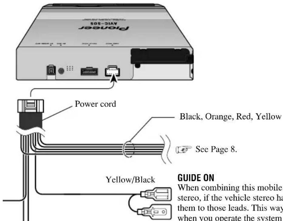
Connecting the power cord (1) 8
Connecting the power cord (2) 9
Installation 11
CAUTION 11
To guard against electromagnetic interference ....12
Before installing and fixing 12
Before using the adhesive tape 12
Installing the main unit 13
● Installation notes
- Parts supplied
- Installing the main unit inside the boot, on the floor under a seat, etc., using tapping screws
Installing the GPS antenna 16
● CAUTION
- Installation notes
● Parts supplied
- When installing the antenna inside the vehicle (on the dashboard or rear shelf)
- When installing the antenna outside the vehicle (on the body)
Installing the commander 19
● Parts supplied
- Loading the batteries
● Battery notes
● Installing the commander with velcro tape
- Commander handling notes
Installing the microphone 21
● Installation notes
● Parts supplied
- When installing the microphone on the sun visor
- When installing the microphone on the steering column
After installing the unit 24
PLEASE READ ALL OF THESE INSTRUCTIONS REGARDING YOUR MOBILE NAVIGATION SYSTEM AND RETAIN THEM FOR FUTURE REFERENCE.
- Read this manual fully and carefully before installing your mobile navigation system.
- Keep this manual handy for future reference.
- Pay close attention to all warnings in this manual and follow the instructions carefully.
- This navigation system is intended solely as an aid to you in the operation of your vehicle. It is not a substitute for your attentiveness, judgement and care while driving. Do not operate your navigation system if doing so will divert your attention from the safe operation of your vehicle. Always observe safe driving rules and follow all existing traffic regulations.
-
This navigation system may in certain circumstances display erroneous information regarding the position of your vehicle, the distance of objects shown on the screen, and compass directions. In addition, the system has certain limitations, including the inability to identify one-way streets, temporary traffic restrictions and potentially unsafe driving areas. Please exercise your own judgement in light of actual driving conditions.
-
As with any accessory in your vehicle's interior, the navigation system should not divert your attention from the safe operation of your vehicle. If you experience difficulty in operating the system or reading the display, please make adjustments while safely parked.
- Do not attempt to install or service your mobile navigation unit by yourself. Installation or servicing of the Mobile Navigation Unit by persons without training and experience in electronic equipment and automotive accessories may be dangerous and could expose you to the risk of electric shock or other hazards.
- Please remember to wear your seat belt at all times while operating your vehicle. If you are ever in an accident, your injuries can be considerably more severe if your seat belt is not properly fastened.

CAUTION
- Pioneer does not recommend that you install or service your navigation unit yourself. Installing or servicing of the product may expose you to risk of electric shock or other hazards. Refer all installation and servicing of your navigation unit to authorised Pioneer service personnel.
- Secure all wiring with cable clamps or electrical tape. Do not allow any bare wiring to remain exposed.
- Do not drill a hole into the engine compartment to connect the orange lead of the unit to the vehicle battery. Engine vibration may eventually cause the insulation to fail at the point where the wire passes from the passenger compartment into the engine compartment. Take extra care in securing the wire at this point.
- It is extremely dangerous to allow the GPS antenna lead or microphone lead to become wound around the steering column or gearstick. Be sure to install the unit in such a way that it will not obstruct driving.
- Make sure that wires will not interfere with moving parts of the vehicle, such as the gearstick, hand brake or seat sliding mechanism.
- Do not route wires where they will be exposed to high temperatures. If the insulation heats up, wires may become damaged, resulting in a short circuit or malfunction.
- Do not cut the GPS antenna lead to shorten it or use an extension to make it longer. Altering the antenna cable could result in a short circuit or malfunction.
- Do not shorten any leads. If you do, the protection circuit may fail to work properly.
- Never feed power to other electronic products by cutting the insulation of the power supply lead of the navigation unit and tapping into the lead. The current capacity of the lead will be exceeded, causing overheating.
Before installing the unit
- This unit is designed for vehicles with a 12-volt battery and negative grounding. Before installing the system (especially in a recreational vehicle, lorry, or bus), check the battery voltage.
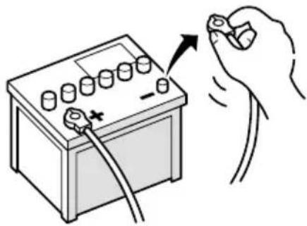
- Disconnect the negative (−) terminal of the battery to avoid the risk of a short circuit.
natural_image
Illustration of a hand holding a battery with a tool, showing its connection to the charging terminal (no text or symbols present)To prevent damage
- When disconnecting a connector, pull the connector itself. Do not pull the lead, as you may pull it out of the connector.
- When the unit is installed in vehicles that do not have an ACC (accessory) position on the ignition (as shown in Fig. 2), be sure to connect the red lead of the unit to the terminal controlled by the ignition switch ON/OFF position. If you do not, the vehicle battery may be drained.

ACC position

No ACC position
Fig. 1
Fig. 2
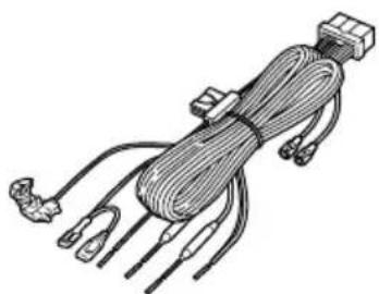
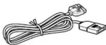
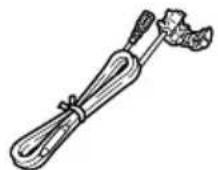
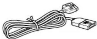
Parts supplied
natural_image
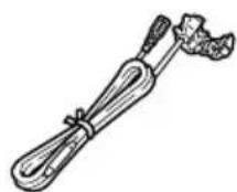
Illustration of a coiled cable with connectors and terminal blocks (no text or symbols)Power cord
natural_image
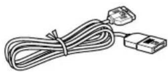
Line drawing of a cable with two connectors (no text or symbols)
Purple lead extension cordRGB cable

ConnectorPink lead extension cord
Connecting the system
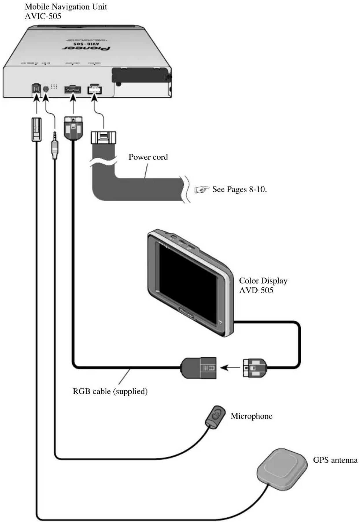
flowchart
graph TD
    A["Power cord"] -->|See Pages 8-10.| B["Color Display AVD-505"]
    B --> C["RGB cable (supplied)"]
    C --> D["Microphone"]
    D --> E["GPS antenna"]
    A --> F["Mobile Navigation Unit AVIC-505"]
Connecting the power cord (1)
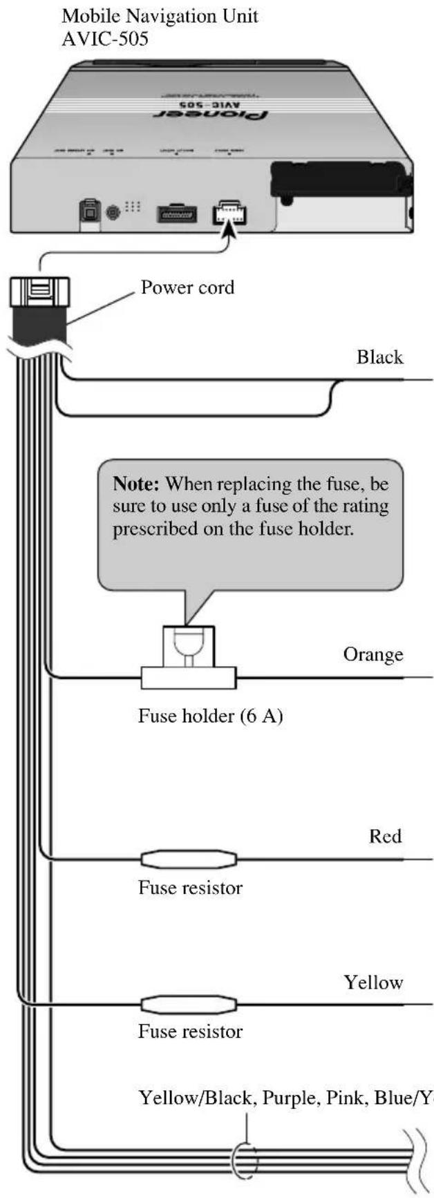
GROUND
To vehicle (metal) body. To keep electromagnetic noise from the vehicle body out of the mobile navigation system, attach this lead near the main unit.
Note: The orange, red, and yellow leads should be connected to the opposite side of the fusebox terminals from the battery.
+ Battery
To the terminal always supplied with power regardless of ignition switch position.
ACC
To the electric terminal controlled by the ignition switch (12 V DC) ON/OFF.
Do not connect this lead to power source terminals to which power is continuously supplied. If the lead is connected to such terminals, the battery may be drained.
ILL
To lighting switch terminal.

See next page.
Connecting the power cord (2)
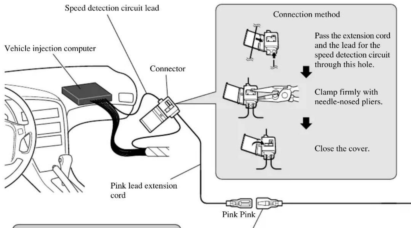
flowchart
graph TD
    A["Vehicle injection computer"] --> B["Speed detection circuit lead"]
    B --> C["Connector"]
    C --> D["Pink lead extension cord"]
    D --> E["Pink Pink"]
    F["Connection method"] --> G["Pass the extension cord and the lead for the speed detection circuit through this hole."]
    G --> H["Clamp firmly with needle-nosed pliers."]
    H --> I["Close the cover."]
Note: The position of the speed detection circuit depends on the vehicle model. For details, consult the relevant documents from Pioneer. When making connections for a model not listed in those documents or for which connection to the speed detection circuit is too difficult, connect the separately sold ND-PG1 speed pulse generator to the pink lead.
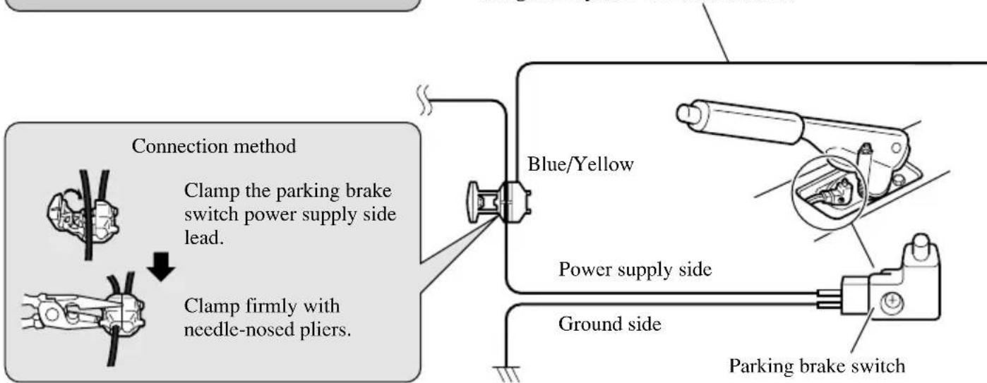
Note: The position of the parking brake switch depends on the vehicle model. For details, consult the vehicle owner's manual or dealer.
CAR SPEED SIGNAL INPUT
The mobile navigation system is connected here to detect the distance the vehicle travels. Always connect the vehicle's speed detection circuit or the ND-PG1 speed pulse generator, sold separately. Failure to make this connection will increase errors in the location display.
PARKING BRAKE
Used to detect the ON/OFF status of the parking brake. This lead must be connected to the power supply side of the parking brake switch. If this connection is made incorrectly or omitted, certain functions of your navigation system will be unusable.
Mobile Navigation Unit AVIC-505
Note: On some model's reverse the + and - leads for the backup lamp are reversed. Connect the purple lead to the lead whose voltage changes when the reverse gear is engaged.
This is connected so that the mobile navigation system can detect whether the vehicle is moving forwards or backwards. Always connect to the reversing lamp primary lead.
Purple
Purple
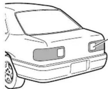
natural_image
Line drawing of a car front bumper with no text or symbolsPurple lead extension cord
Check the position of your vehicle's reversing lamp (the one that lights up when the gearstick is in reverse [R]) and find the reversing lamp + side lead in the trunk.
Connection method
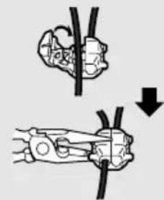
natural_image
Diagram showing two mechanical clamping or fastening techniques with a downward arrow indicating compression (no text or symbols present)Clamp the reversing lamp + side lead.
Clamp firmly with needle-nosed pliers.
Fuse resistor
Reversing lamp + side lead.

CAUTION
- Pioneer does not recommend that you install or service your navigation unit yourself. Installing or servicing the product may expose you to risk of electric shock or other hazards. Refer all installation and servicing of your navigation unit to authorised Pioneer service personnel.
- Never install the unit in places where:
* It could injure the driver or passengers if the vehicle stops suddenly.
* It may interfere with the driver's operation of the vehicle, such as on the floor in front of the driver's seat.
- Make sure there is nothing behind the dashboard or panelling when drilling holes in them. Be careful not to damage fuel lines, brake lines or power cables.
- When using screws, do not allow them to come into contact with any electrical lead. Vibration may damage wires, leading to a short circuit or other damage to the vehicle.
- To ensure proper installation, use the supplied parts in the manner specified. If any parts other than the supplied ones are used, they may damage internal parts of the unit or they may work loose and the unit may become detached.

CAUTION
- It is extremely dangerous to allow the GPS antenna lead or microphone lead to become wound around the steering column or gearstick. Be sure to install the unit in such a way that it will not obstruct driving.
- Make sure that leads cannot get caught in a door or the sliding mechanism of a seat, resulting in a short circuit.
- Please confirm the proper function of your vehicle's other equipment following installation of the navigation unit.
To guard against electromagnetic interference
- To keep electromagnetic noise out of the mobile navigation system, do not install the main unit or GPS antenna near the vehicle stereo FM/MW/LW antenna or the FM/MW/LW antenna cord. Such electromagnetic noise would increase the error for the location display.
Before installing and fixing
- Make temporary connections first to check that the unit and system are working properly.
Before using the adhesive tape
- Make sure the surface is free of moisture, dust, grime, oil, etc. before affixing the tape.
Installing the main unit
Installation notes
- Do not install the main unit in places where it may become subject to high temperatures or humidity, such as:
* Places close to a heater outlet.
* Places exposed to direct sunlight, such as on top of the dashboard or the rear shelf.
- Places that may be splashed by rain, for example close to the door.
- The installation strength will depend on the vehicle model and the installation position. Choose a position where the main unit can be firmly installed, and install it securely. If the main unit is not securely fastened, the errors in location display will be greater.
- Do not install the main unit on the board covering the spare tyre or other places which are subject to vibration.
- When the main unit is installed under a front seat, ensure that it does not obstruct the sliding action of the seat.
- Do not install the main unit where it will be under luggage. Strong mechanical shock to the main unit would increase the errors in location display.
- Avoid installing the main unit in places where it will interfere with loading and unloading of the spare tyre, jack, tools, etc.
- Check that a CD-ROM can be ejected with the main unit installed.
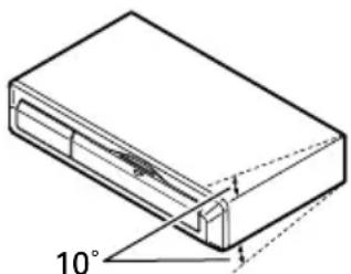
- Install the main unit on a surface within 10^ tolerance. A surface tilted more than this would increase the errors in location display.
natural_image
Technical line drawing of a rectangular electronic component with an 10° angle标注 (no text or symbols beyond the angle marker)- If you use the mobile navigation system out of areas where PIONEER is permitted, your position is not shown properly.
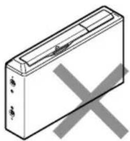
- Do not install the main unit vertically. Installing it this way can cause it to function improperly.
natural_image
Isometric line drawing of a rectangular electronic device with a central port and two ports, crossed out by a gray X (no text or symbols)
natural_image
Simple line drawing of a rectangular device with a cross mark on the side (no text or symbols)Parts supplied
natural_image
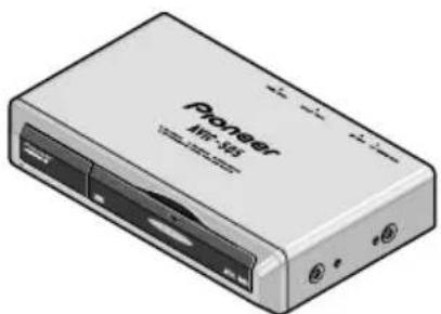
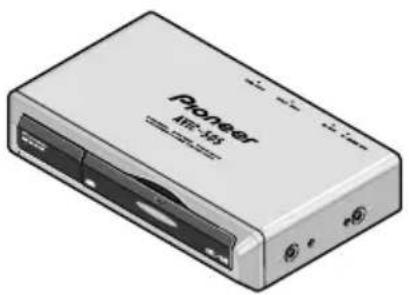
Illustration of a generic electronic device labeled 'Pioneer' with ports and connectors (no readable text beyond branding)Main unit
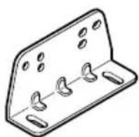
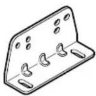
Mounting angle (2 pcs.)
Screw
(5 × 8 mm)
(4 pcs.)
Tapping screw (6 × 16 mm) (4 pcs.)
Installing the main unit inside the boot, on the floor under a seat, etc.,
using tapping screws
1. Fit the mounting brackets to the sides of the main unit.
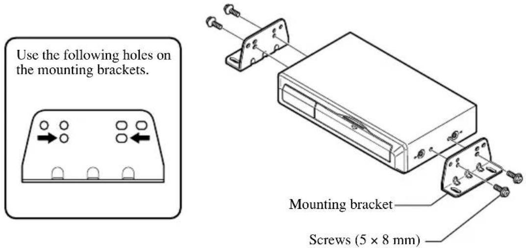
2. Fix to the floor with tapping screws.
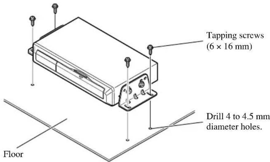

CAUTION
- Before drilling any mounting holes, confirm that the screws will not interfere with any of the vehicle's operating systems (such as the fuel line, brake lines, electrical wiring, etc.).
Installing the GPS antenna

CAUTION
- Do not cut the GPS antenna lead to shorten it or use an extension to make it longer. Altering the antenna cable could result in a short circuit.
Installation notes
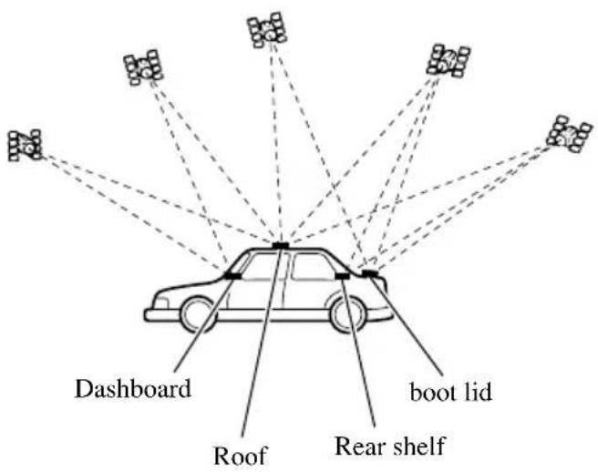
- The antenna should be installed on a level surface where radio waves will be blocked as little as possible. Radio waves cannot be received by the antenna if reception from the satellite is blocked. Installation on the vehicle roof or boot lid is recommended to enable best reception.
- When installing the GPS antenna inside the vehicle, be sure to use the metal sheet provided with your system. If this is not used, the reception sensitivity will be poor.
- Do not cut the accessory metal sheet. This would reduce the sensitivity of the GPS antenna.
• Take care not to pull the antenna lead when removing the GPS antenna. The magnet attached to the antenna is very powerful, and the lead may become detached. - The GPS antenna is installed with a magnet. When installing the GPS antenna, be careful not to scratch the vehicle body.
- When installing the GPS antenna on the outside of the vehicle, always put it in the vehicle when going through an automatic vehicle wash. If it is left on the outside it may be knocked off and scratch the vehicle body.
- Do not paint the GPS antenna, as this may affect its performance.
Parts supplied

Waterproof padClamp (5 pcs.)
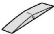
When installing the antenna inside the vehicle (on the dashboard or rear shelf)
Affix the metal sheet on as level a surface as possible where the GPS antenna faces outside the window. Place the GPS antenna on the metal sheet. (The GPS antenna is fastened with its magnet.)
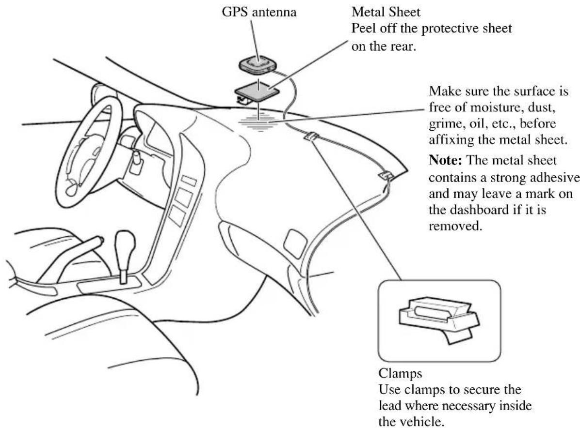
Note:
- Some models use window glass that does not allow signals from GPS satellites to pass through. On such models, install the GPS antenna on the outside of the vehicle.
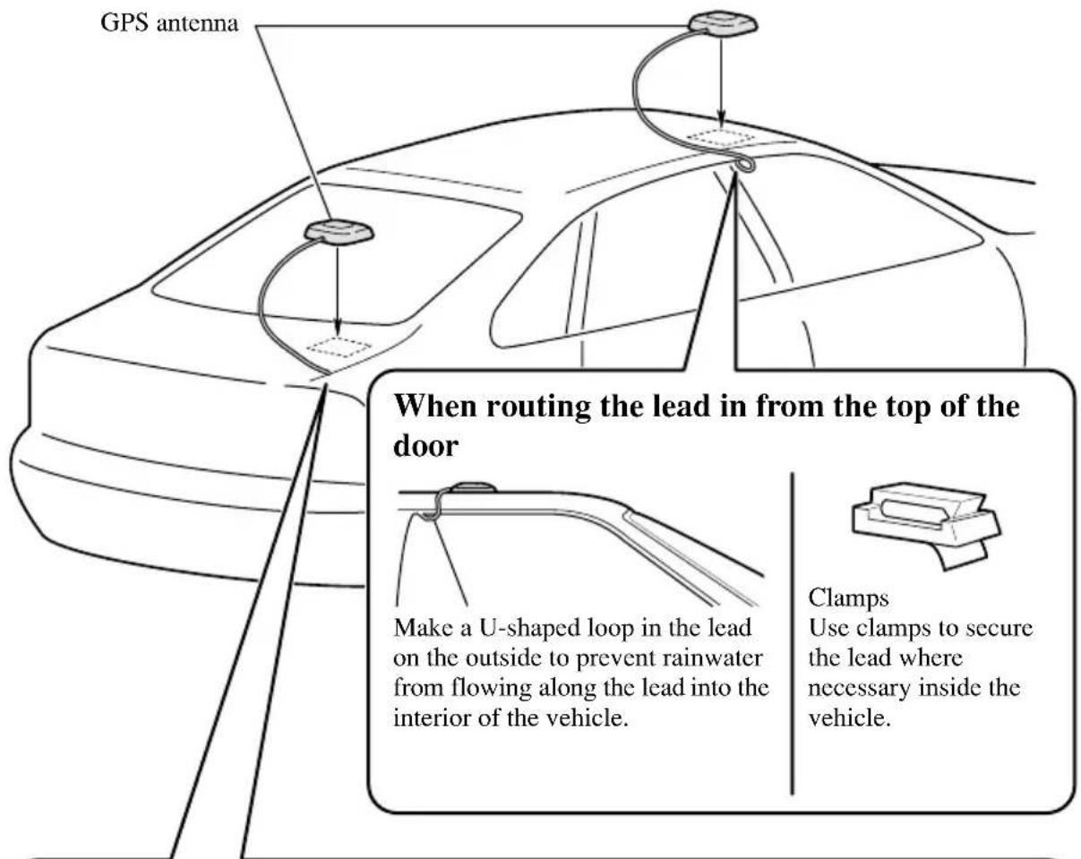
When installing the antenna outside the vehicle (on the body)
Put the GPS antenna in a position as level as possible, such as on the roof or boot lid. (The GPS antenna is fastened with a magnet.)
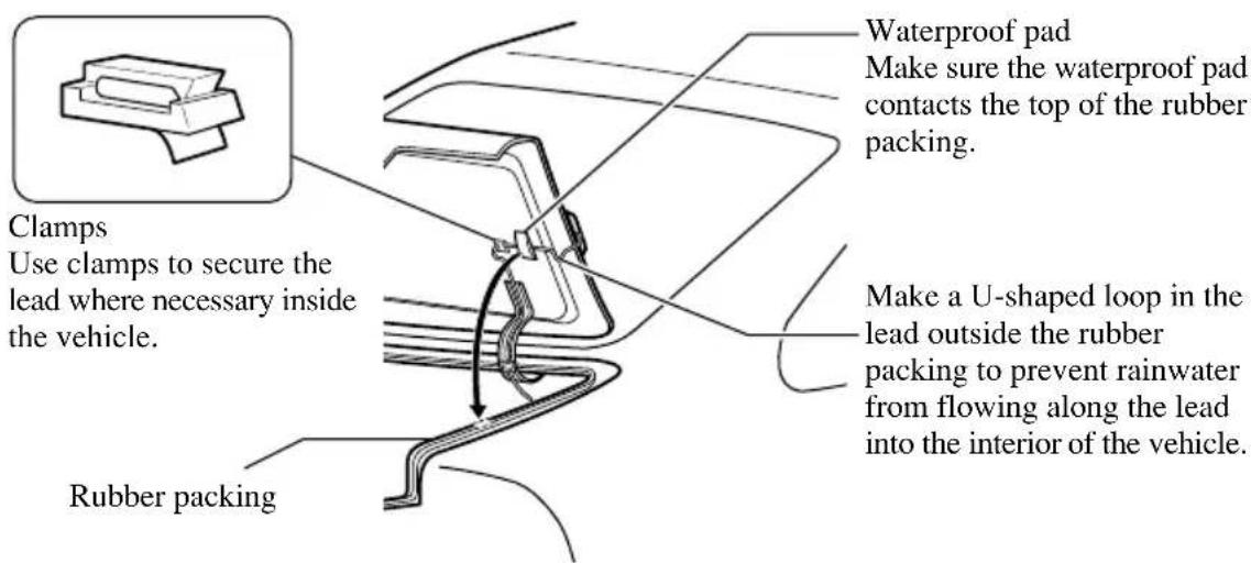
When routing the lead in from inside the boot
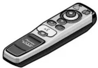
Installing the commander
Parts supplied
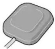
natural_image
Illustration of a remote control device with buttons and a 'Control Panel' button (no text or symbols on the device itself)Commander
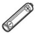
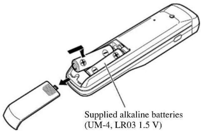
Alkaline battery (UM-4, LR03 1.5 V) (2 pcs.)
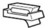
natural_image
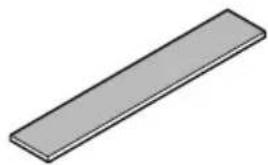
Simple 3D illustration of a rectangular prism (no text or symbols)Velcro tape (large) (Soft side)

Velcro tape (small)
(Rough side)
(2 pcs.)
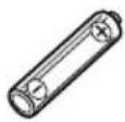
Loading the batteries
Battery notes
- Be sure that the batteries are loaded with the positive (+) and negative (−) terminals in their correct positions.
- Do not mix new and old batteries.
- Do not mix different types of batteries. Even if the shape is the same, the voltage may be different.
- Remove the batteries from the commander when it will not be used for a long period of time.
- If leakage has occurred, completely wipe off any liquid from the battery compartment, before loading new batteries.
• These batteries can not be recharged. - When you replace the batteries, we recommend alkaline batteries.
Installing the commander with velcro tape
Affix the small pieces of Velcro tape provided (rough side) to the rear surface of the commander, and the large piece of Velcro tape (soft side) to the installation surface.
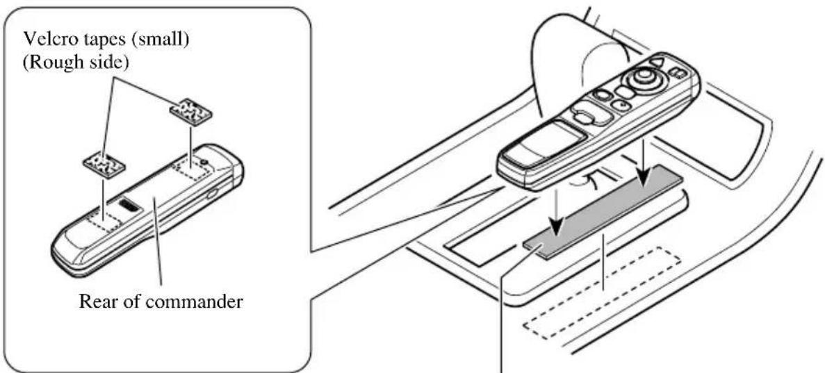
Affix the Velcro tapes where it will not obstruct opening and closing of the rear battery cover.
Velcro tape (large) (Soft side)
Commander handling notes
• Always keep the commander protected from direct sunlight or high temperatures.
Leaving the commander in places exposed to direct sunlight or high temperatures for long periods of time may cause deformation, discolouration or malfunction.
- Replace the batteries when the commander's performance deteriorates.
Installing the microphone
Installation notes
• Install the microphone in a position and orientation that will enable it to pick up the voice of the person operating the system.
Parts supplied
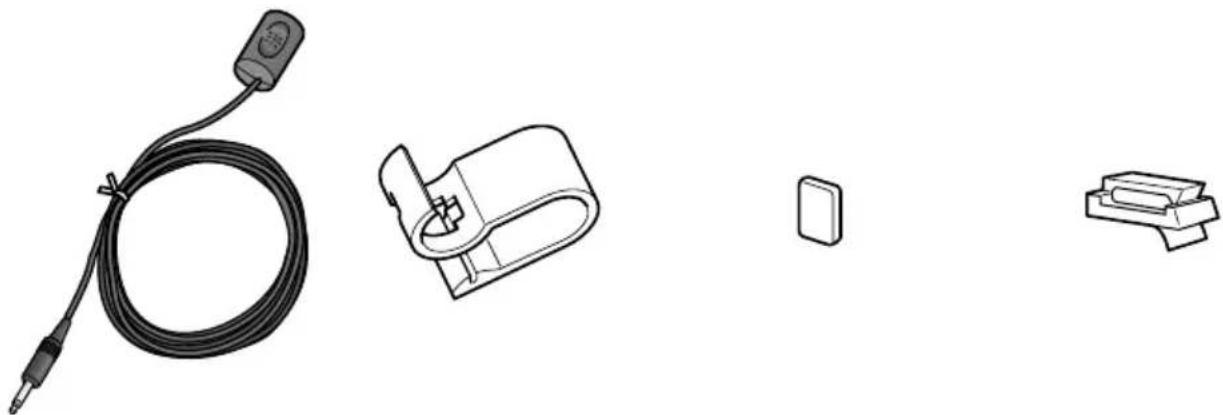
natural_image
Illustration of four electronic components: a coiled cable, a connector, a small rectangular component, and a separate bracket (no text or symbols)Double-sided tape Microphone clip Microphone (5 pcs.)
When installing the microphone on the sun visor
1. Install the microphone on the microphone clip.
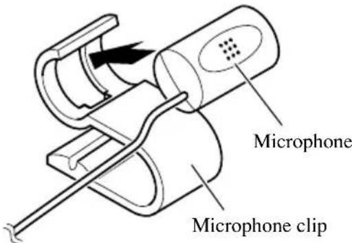
2. Install the microphone clip on the sun visor.
With the sun visor up, install the microphone clip. (Lowering the sun visor reduces the recognition rate for voice operations.)
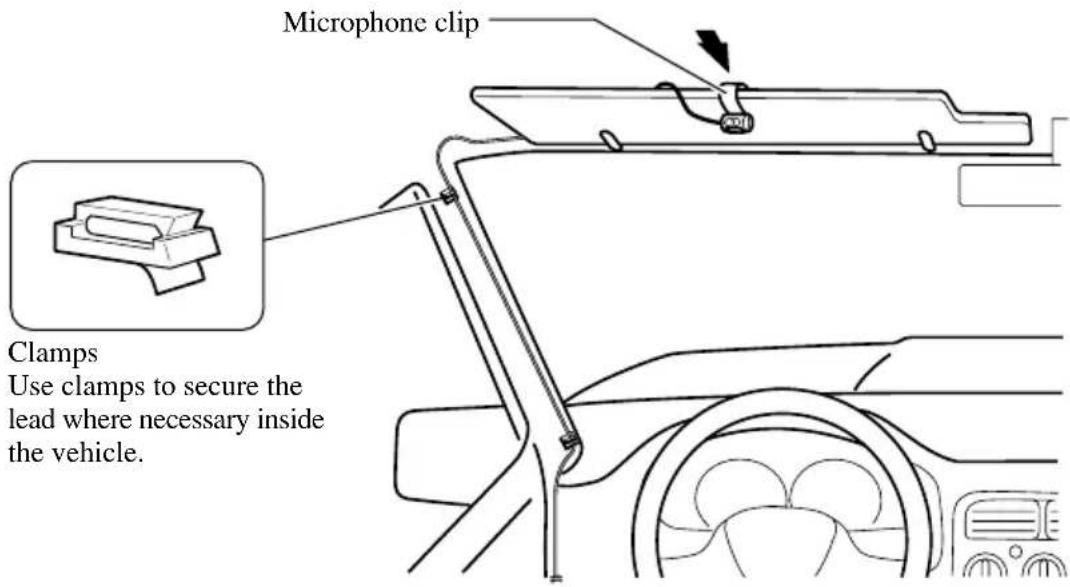
When installing the microphone on the steering column
- Install the microphone on the microphone clip.
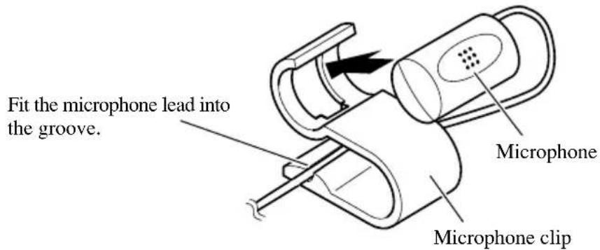
- Install the microphone clip on the steering column.
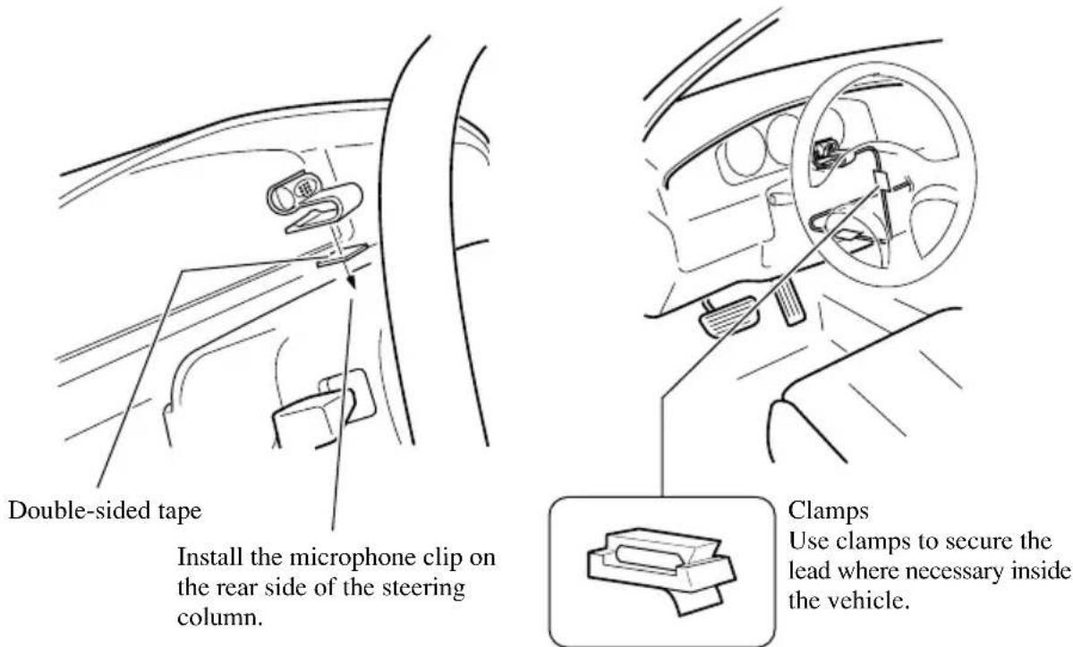

CAUTION
- It is extremely dangerous to allow the microphone lead to become wound around the steering column or gearstick. Be sure to install the unit in such a way that it will not obstruct driving.
After installing the unit
1. Reconnecting the battery.
First, double-check that all connections are correct and that the unit is installed correctly. Reassemble all vehicle components that you previously removed. Then reconnect the negative (−) cable to the negative (−) terminal of the battery.
2. Start the engine.
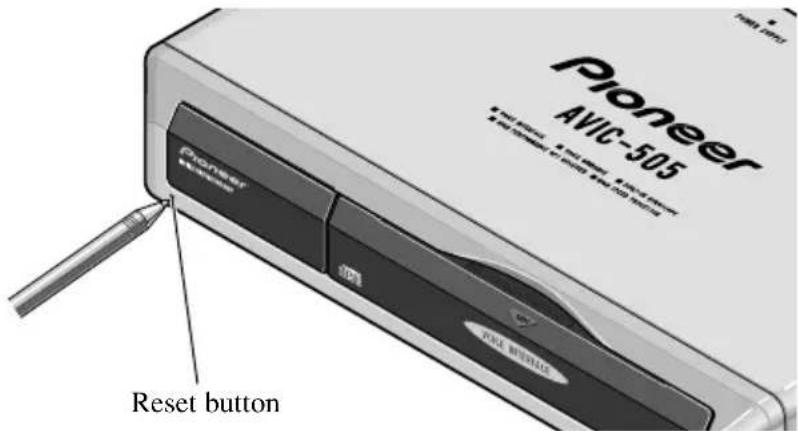
3. Press the reset button on the main unit.
Press the reset button on the main unit using a pointed object such as the point of a pen.
4. Set the mobile navigation system.
Set the mobile navigation system as explained in the Owner's manual.
natural_image
Illustration of a hand holding a battery with a tool, showing components and wiring (no text or symbols)Para impedir daños
natural_image
Illustration of a cable with multiple connectors and wires (no text or symbols)natural_image
Line drawing of a cable with connectors and a connector (no text or symbols)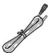
natural_image
Diagram showing two mechanical clamping or clamp mechanisms with a downward arrow indicating compression (no text or symbols present)natural_image
Line drawing of a car front bumper with no text or symbolsnatural_image
Technical line drawing of a rectangular electronic component with a 10° angle标注 (no text or symbols beyond the angle marker)natural_image
Isometric line drawing of a rectangular electronic device with a cross symbol overlay (no text or symbols present)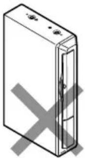
natural_image
Simple line drawing of a rectangular device with a cross mark on the side (no text or symbols)Partes suministradas
natural_image
Illustration of a beige Pioneer 4MHz 30S device with ports and connectors (no text or symbols on body)Unidad principal
natural_image
Illustration of a remote control device with buttons and a display screen (no text or symbols visible)Mando a distancia

natural_image
Simple 3D illustration of a rectangular prism (no text or symbols)Cinta Velcro (grande) (Lado blando)
natural_image
Illustration of a hand holding a battery with a pliers, showing terminal connections and polarity (no text or symbols)natural_image
Illustration of a coiled cable with connectors and connectors (no text or symbols)Betriebsstromkabel
natural_image
Line drawing of a cable with connectors and a connector (no text or symbols)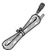
natural_image
Diagram showing two mechanical clamping or fastening techniques with a downward arrow indicating compression (no text or symbols present)natural_image
Line drawing of a car front bumper with no text or symbolsnatural_image
Technical line drawing of a rectangular electronic component with an 10° angle标注 (no text or symbols beyond the angle marker)natural_image
Isometric line drawing of a rectangular electronic device with a gray X symbol overlay (no text or symbols)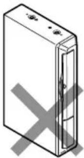
natural_image
Isometric line drawing of a rectangular electronic device with a cross mark on its side (no text or symbols)Mitgelieferte Teile
natural_image
Illustration of a beige Pioneer 402-105 wireless device with ports and connectors (no text or symbols on body)Navigationseinheit

Winkelblech (2 Stck.)

Schraube
(5 × 8 mm)
(4 Stck.)
natural_image
Simple line drawing of a stacked rectangular object (no text or symbols)Kabelklemmen
natural_image
Illustration of a remote control device with buttons and a 'Control Panel' button (no text or symbols on the device itself)Bedienungsteil

Alkalibatterien
(UM-4, LR03, 1,5 V)
(2 Stck.)

natural_image
Simple 3D illustration of a rectangular prism (no text or symbols)natural_image
Illustration of a hand holding a battery with a plug inserted, showing wiring and polarity (no text or symbols)natural_image
Illustration of a coiled cable with connectors and wires, no text or symbols presentnatural_image
Line drawing of a cable with two connectors (no text or symbols)
Cordon-rallonge pourpreCâble RVB (Ecr
natural_image
Mechanical clamp or tool diagram showing a joint with a downward arrow indicating force or direction (no text or symbols present)natural_image
Line drawing of a car front bumper with no text or symbolsCordon-rallonge pourpre
natural_image
Technical line drawing of a rectangular electronic component with a 10° angle标注 (no text or symbols beyond the angle marker)natural_image
Isometric line drawing of a rectangular electronic device with a cross symbol overlay (no text or symbols present)
natural_image
Isometric line drawing of a rectangular device with a cross mark on its side (no text or symbols)Pièces fournies
natural_image
Illustration of a beige Pioneer 4bit CD-ROM device with ports and control buttons (no text or symbols on body)Unité principale
natural_image
Technical line drawing of a metal bracket with multiple holes and mounting holes (no text or symbols)natural_image
Illustration of a remote control device with buttons and a display screen (no text or symbols visible)Télécommande

natural_image
Simple 3D illustration of a rectangular prism (no text or symbols)natural_image
Illustration of four electronic components: a coiled cable, a connector, a small rectangular component, and a separate bracket (no text or symbols)natural_image
Illustration of a hand holding a battery with a plug inserted, showing wiring and polarity (no text or symbols)Per evitare danni
natural_image
Illustration of a coiled cable with connectors and wires, no text or symbols presentnatural_image
Line drawing of a cable with two connectors (no text or symbols)
natural_image
Line drawing of a car front bumper with no text or symbolsnatural_image
Diagram showing two mechanical clamping or fastening techniques with a downward arrow indicating compression (no text or symbols present)natural_image
Technical line drawing of a rectangular electronic component with an 10° angle标注 (no text or symbols beyond the angle marker)natural_image
Isometric line drawing of a rectangular electronic device with a cross symbol overlay (no text or symbols present)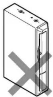
natural_image
Isometric illustration of a rectangular device with internal components and a cross mark, no text or symbols present.Pezzi in dotazione

natural_image
Illustration of a Pioneer 4bit CD-ROM device (no text or symbols on body)Unità principale
natural_image
Illustration of a remote control device with buttons and a 'HUAAN' button (no text or symbols on the device itself)Telecomando
Pila alcalina
(UM-4, LR03 1,5 V)
(2 pz.)

natural_image
Simple 3D illustration of a rectangular prism (no text or symbols)Nastro velcro (grande) (lato morbido)

Nastro velcro
(piccolo)
(lato ruvido)
(2 pz.)
natural_image
Simple line drawing of a stacked rectangular object (no text or symbols)natural_image
Illustration of a hand holding a battery with a plug inserted, showing wiring and polarity (no text or symbols)natural_image
Illustration of a coiled cable with connectors and connectors (no text or symbols)Stroomsnoer
natural_image
Line drawing of a cable with two connectors, no text or symbols present
natural_image
Mechanical diagram showing two hands operating a tool, one with a curved arrow indicating motion (no text or symbols present)natural_image
Line drawing of a car front bumper with no text or symbolsnatural_image
Technical line drawing of a rectangular electronic component with a 10° angle标注 (no text or symbols beyond the angle marker)natural_image
Isometric line drawing of a rectangular electronic device with a cross symbol overlay (no text or symbols present)
natural_image
Isometric line drawing of a rectangular electronic device with a cross mark on its side (no text or symbols)natural_image
Illustration of a Pioneer 4863 audio device (no text or symbols on body)Hoofdapparaat
natural_image
Illustration of a remote control device with buttons and a 'Control Panel' button (no text or symbols on the device itself)Afstandsbediening

Alkalibatterij
(UM-4, LR03 1,5 V)
(2 stuks)

natural_image
Simple 3D illustration of a rectangular prism (no text or symbols)natural_image
Illustration of four electronic components: a coiled cable, a connector, a small rectangular component, and a separate bracket (no text or symbols)France: tapez 36 15 PIONEER
PIONEER ELECTRONIC CORPORATION
4-1, Meguro 1 chome, Meguro-ku, TOKYO, 153-8654, JAPAN
PIONEER ELECTRONICS (USA) INC.
P.O. Box 1760, Long Beach, California 90801, U.S.A.
TEL: (800) 421-1404
PIONEER ELECTRONIC (EUROPE) N.V.
Haven 1087 Keetberglaan 1, 9120 Melsele, Belgium
TEL: (0) 3/570.05.11
PIONEER ELECTRONICS AUSTRALIA PTY. LTD.
178-184 Boundary Road, Braeside, Victoria 3195, Australia
TEL: (03) 580-9911
PIONEER ELECTRONICS OF CANADA, INC.
300 Allstate Parkway Markham, Ontario L3R 0P2, Canada
TEL: (905) 479-4411
PIONEER ELECTRONICS DE MEXICO, S.A. de C.V.
San Lorenzo Num 1009 3er piso Desp. 302
Col. Del Valle, Mexico D.F. C.P. 03100
TEL: 5-688-52-90
Published by Pioneer Electronic Corporation.
Copyright © 1998 by Pioneer Electronic
Corporation. All rights reserved.
Publication de Pioneer Electronic Corporation.
© 1998 Pioneer Electronic Corporation.