AVICF80DAB - GPS Navigation System PIONEER - Free user manual and instructions
Find the device manual for free AVICF80DAB PIONEER in PDF.

| Product type | GPS navigation system with DAB+ digital radio |
| Brand | Pioneer |
| Model | AVIC-F80DAB |
| Dimensions (W x H x D) | Approx. 178 x 100 x 160 mm (2 DIN format) |
| Weight | Approx. 2 kg |
| Power supply | 12 V DC (vehicle battery), negative ground |
| Fuse | 10 A |
| Power consumption | Less than 10 A (with active DAB antenna) |
| Screen | WVGA color LCD touchscreen |
| Main functions | GPS navigation, DAB+/FM/AM reception, Bluetooth, Apple CarPlay, Android Auto, MirrorLink, HDMI/USB/AUX inputs, rearview camera |
| Connectivity | Wi-Fi, Bluetooth, USB ports (x2), HDMI, video input, rear video output, AUX audio input |
| Maintenance and cleaning | Wipe with a soft dry cloth. Do not use chemical products. |
| Safety | Parking brake detection (light green wire), speed signal input (pink), reverse gear input (violet/white), video lock while driving |
| Installation | 2 DIN front mount, screw or side bracket fixing |
| Operating temperature | -10°C to +60°C |
| Repairability and spare parts | Spare parts available through Pioneer network. Repair by authorized professional recommended. |
| General information | Manual available in multiple languages. Map update via PC/DVD. |
Frequently Asked Questions - AVICF80DAB PIONEER
User questions about AVICF80DAB PIONEER
0 question about this device. Answer the ones you know or ask your own.
Ask a new question about this device
Download the instructions for your GPS Navigation System in PDF format for free! Find your manual AVICF80DAB - PIONEER and take your electronic device back in hand. On this page are published all the documents necessary for the use of your device. AVICF80DAB by PIONEER.
USER MANUAL AVICF80DAB PIONEER
Precautionsbeforeconnectingthe system5
Beforeinstallingthisproduct5
Topreventdamage6
-Noticefortheblue/whitelead6
Partssupplied7
Connectingthepowercord(1)8
Connectingthepowercord(2)10
Connectingthesystem12
Connectingtoseparatelysoldpower amp13
ConnectinganiPod/iPhoneoranAndroid device14
Attaching identification label to USB cables15
ConnectinganiPhonewithLightning connector15
-ConnectingviatheUSBport (iPhone)15
-ConnectingviatheHDMIport (iPhone)16
-ConnectingviatheRGBinput (iPhone)16
ConnectinganiPhonewith30-pin connector17
-ConnectingviatheAUXinput (iPhone)17
-ConnectingviatheRGBinput (iPhone)18
ConnectingtheAndroid™ device18
-ConnectingviatheHDMIport(Android device)18
-ConnectingviatheMHLport(Android device)19
ConnectingviatheUSBport(Android device)19
SecuringtheHighSpeedHDMI ^® Cable20
Connectingarearviewcamera20
Connectingtheexternalvideo component21
-UsingAVinput21
-UsinganAUXinput22
ConnectinganHDMIdevice23
Connectingthereardisplay24
-When using areardisplayconnectedto rearvideooutput24
03 Installation
Precautionsbeforeinstallation25
Toavoidelectromagneticinterference25
Beforeinstalling25
-ForAVIC-F88DABandAVIC-F80DAB users26
Installingthisproduct26
-Installationwiththeholder27
-Installationusingthescrewholeson thesideofthisproduct28
InstallingtheGPSaerial29
-Wheninstallingtheaerialinsidethe vehicle(onthedashboardorrear shelf)30
Installingthemicrophone31
-Partssupplied31
-Mountingonthesunvisor31
-Installationonthesteeringcolumn32
-Adjustingthemicrophoneangle32
04 Afterinstallation
Afterinstallingthisproduct33
Yournewproductandthis manual
- Thenavigationfeaturesofthisproduct (andtherearviewcameraoptionifpur-chased)areintendedsolelytoaidyouin theoperationofyourvehicle.Itisnotasub-stituteforyourattentiveness,judgement andcarewhendriving.
- Neverusethisproducttoroutetohospitals,policestations,orsimilarfacilitiesin anemergency.Pleasecalltheappropriate emergencynumber.
- Donotoperatethisproduct,anyapplications,ortherearviewcameraoption(ifpurchased)ifdoingsowilldivertyourattentioninanywayfromthesafeoperationofyourvehicle.Alwaysobservesafedrivingrulesandfollowallexistingtrafficregulations.Ifyouexperienceddifficultyinoperatingthisproductorreadingthedisplay,parkyourvehicleinasafelocationandapplythehandbrakebeforemakingthenecessaryadjustments.
- Thismanualeexplainshowtoinstallthis productinyourvehicle.Operationofthis productisexplainedintheseparatemanuals.
- Donotinstallthisproductwhereitmay(i) obstructthedriver'svision,(ii)impairthe performanceofanyofthevehicle'soperatingsystemsofsafetyfeatures,including airbags,hazardlampbuttons,or(iii)impair thedriver'sabilitytosafelyoperatethevehicle.Insomecases,itmaynotbepossible toinstallthisproductbecauseofthevehicletypeortheshapeofthevehicleinterior.
- Modeliconsshowninthismanualindicate thatthedescriptionisintendedforthe modelsindicatedbytheicons. Ifthefollowingiconisshown,thedescriptionisappliedonlytothemodelshown. e.g.)
F88DAB
• Thegraphicalsymbolplacedon theproductmeansdirectcurrent.

Important safeguards
WARNING
Pioneerdoesnotrecommendthatyouinstall thisproductyourself.Thisproductisdesignedforprofessionalinstallationonly.We recommendthatonlyauthorisedPioneerservicepersonnel,whohavespecialtraining andexperienceinmobileelectronics,setup andinstallthisproduct.NEVERSERVICE THISPRODUCTYOURSELF.Installingor servicingthisproductanditsconnecting cablesmayexposeyoutotheriskofelectric shockorotherhazards,andcancausedamagetothisproductthatisnotcoveredby warranty.
- Readthismanualfullyandcarefullybefore installingthisproduct.
- Keep this manual handy for future reference.
- Paycloseattentiontoallwarningsinthis manualandfollowtheinstructionscarefully.
- Thisproductmayincertaincircumstances displayinaccuratepositionofyourvehicle, thedistanceofobjectsshownonthe screen,andcompassdirections.Inaddition,thesystemhascertainlimitations,includingtheinabilitytoidentifyone-way streets,temporarytrafficrestrictionsand potentiallyunsafedrivingareas.Pleaseexerciseyourownjudgementinthelightof actualdrivingconditions.
- Aswithanyaccessoryinyourvehicle'sinterior, thisproductshouldnotdivertyourattentionfromthesafeoperationofyourvehicleasitmayresultinseriousinjuryordeath. Ifyouexperienceddifficultyinoperatingthesystemorreadingthedisplay, pleasemakeadjustmentswhilesafelyparked.
- Pleaseremembertowearyourseatbeltat alltimeswhileoperatingyourvehicle. If youareinanaccident, yourinjuriescan be considerably more severe if yourseatbelt is not properly fastened.
01 (Precautions
- Certaincountryandgovernmentlawsmay prohibitorrestricttheplacementanduse ofthisproductinyourvehicle.Pleasecomplywithallapplicablelawsandregulations regardingtheuse,installationandoperationofthisproduct.
Precautionsbefore connectingthesystem

WARNING
Donottakeanystepstotamperwithordisablethehandbrakeinterlocksystemwhich isinplaceforyourprotection.Tampering withordisablingthehandbrakeinterlock systemcouldresultinseriousinjuryor death.

CAUTION
- If you decide to perform the installation yourself, and have special training and experience in them mobile electronics installations, please carefully follow all of the steps in the installation manual.
- Secureallwiringwithcableclampsor electricaltape.Donotallowanybarewiringtoremainexposed.
- Donotdirectlyconnecttheyellowleadof thisproducttothevehiclebattery.If the leadisdirectlyconnectedtothebattery, enginevibrationmayeventuallycause theinsulationtofailatthepointwhere thewirepassesfromthepassengercompartmentintotheenginecompartment.If theyellowlead'sinsulationtearsasaresultofcontactwithmetalparts,short-circuitingcanoccur,resultingin considerabledanger.
- Itisextremelydangeroustoallowcables tobecomewoundaroundthesteeringcolumnorgearstick.Besuretoinstallthis product,itscables,andwiringawayin suchsothattheywillnotobstructorhinderdriving.
- Makesurethatthecablesandwireswill notinterferewithorbecomecaughtin anyofthevehicle'smovingparts,especiallythesteeringwheel,gearstick,hand-brake,slidingseattracks,doors,oranyof thevehicle'scontrols.
- Donotroutewireswheretheywillbeexposedtohightemperatures.Iftheinsulationheatsup,wiresmaybecome
damaged, resulting in an short circuit or malfunction and permanent damage to the product.
- DonotcuttheGPSaerialcabletoshortenitoruseanextensiontomakeitlonger. Alteringtheaerialcablecouldresultina shortcircuitormalfunction.
- Donotshortenanyleads.Ifyoudo,the protectioncircuit(fuseholder,fuseresistororfilter,etc.)mayfailtoworkproperly.
- Neverfeedpowertootherelectronicproductsbycuttingtheinsulationofthe powersupplyleadofthisproductandtappingintothelead.Thecurrentcapacityof theleadwillbeexceeded,causingoverheating.
Beforeinstallingthisproduct
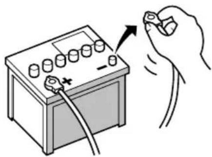
- Use this product with a 12-volt battery and negative earthing only. Failure to dosomay result in a fireormal function.
- To avoid shortsin the electrical system, be suretodisconnectthe(-)batterycablebeforeinstallation.
natural_image
Illustration of a hand holding a battery with a switch and plug, no text or symbols present
Topreventdamage

WARNING
- Usespeakersover50W(maximuminput power)andbetween4Ωto8Ω(impedancevalue).Donotuse1Ωto3Ωspeakersforthisproduct.
- Theblackleadisearth.Pleaseearththis leadseparatelyfromtheearthofhigh-currentproductssuchaspoweramps.Donot earthmorethanoneproducttogether withtheearthfromanotherproduct.For example,youmustseparatelyearthany ampunitawayfromtheearthofthisproduct.Connectingearthstogethercan causeafireand/ordamagetheproductsif theirearthsbecamedetached.
-
Whenreplacingthefuse,besuretoonly useafuseoftheratingprescribedonthis product.
-
Whendisconnectingacon connector, pull the connectoritself. Donotpullthelead, as youmaypullitoutoftheconnector.
- ThisproductcannotbeinstalledinvehiclewithoutACC(accessory)positionontheignitionswitch.


ACCpositionNoACCposition
• To avoid short-circuiting, cover the disconnected lead with insulating tape. It is especially important to insulate all unused speaker leads, which if left uncovered may cause short circuit.
- Attachtheconnectorsofthesamecolour tothecorrespondingcolouredport,i.e., blueconnectortotheblueport,blackto black,etc.
- Refertotheowner'smanualfordetailson connectingthepowerampandotherunits, thenmakeconnectionsaccordingly.
- SinceauniqueBPTLcircuitisemployed, donotdirectlyearththe⊖sideofthe speakerleaderconnectthe⊖sideofan-othersideofthespeakerleadtogether.Be suretoconnectthe⊖sideofthespeaker leadtothe⊖sideofthespeakerleadon thisproduct.
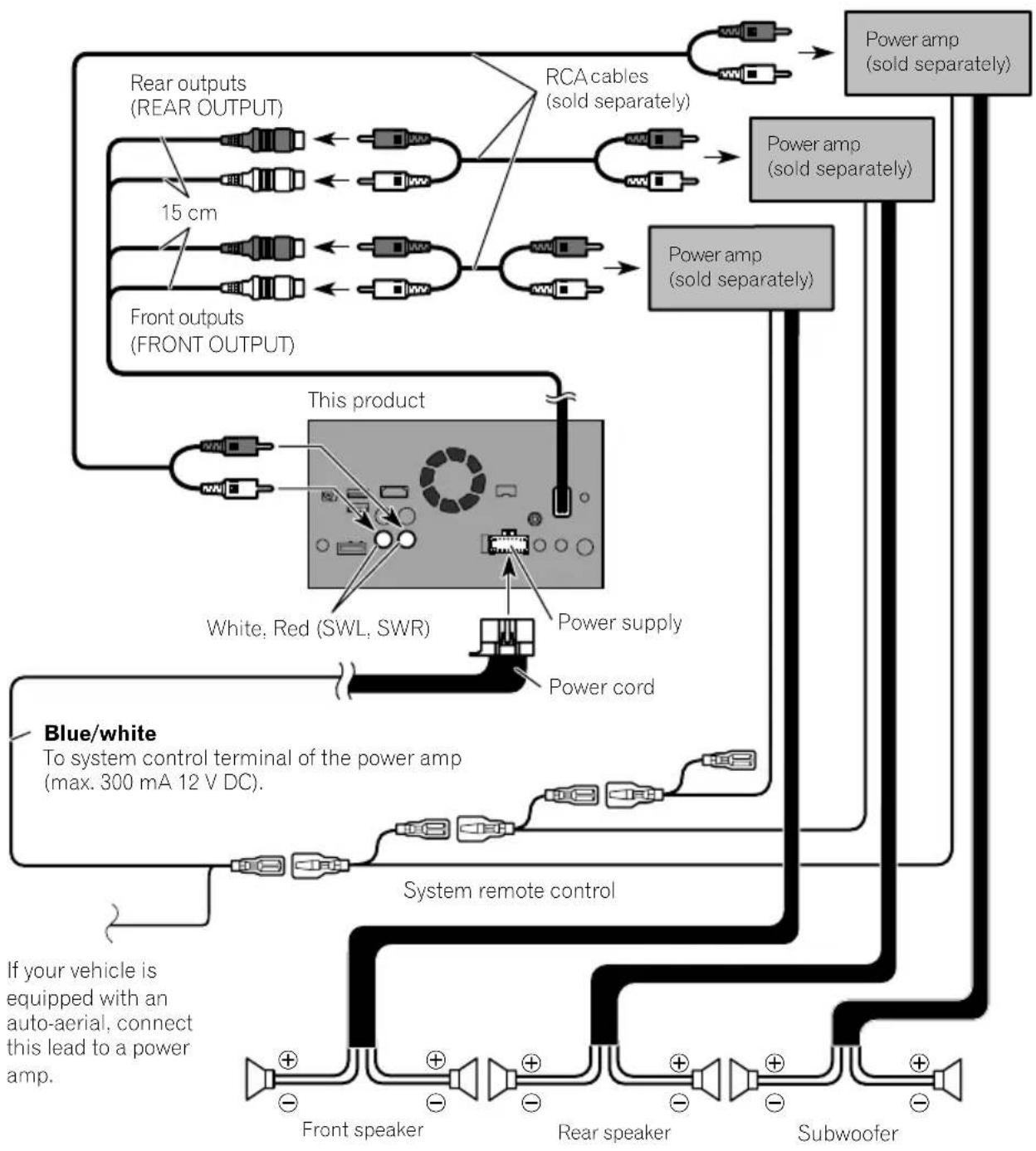
Noticefortheblue/whitelead

Important
Whenthisproductisin"PowerOFF"mode,the controlsignalisalsoturnedoff.If"PowerOFF" modeiscancelled,thecontrolsignalisoutput againandtheaerialisextendedwiththeautoaerialfunction(iftheaerialisbeingused).Becareful sothattheextendedaerialdoesnotcomeinto contactwithanyobstacles.
- Whentheignitionswitchisturnedon(ACC ON),acontrolsignalisoutputthroughthe blue/whitelead.Connecttoanexternal poweramp'ssystemremotecontrolterminal,theauto-aerialrelaycontrolterminal,ortheaerialboosterpowercontrolterminal(max.300mA12VDC).Thecontrolsignal isoutputthroughtheblue/whitelead,even iftheaudiosourceisswitchedoff.
- Besurenottousethisleadasthepower supplyleadfortheexternalpoweramps. Suchconnectioncouldcauseexcessive currentdrainandmalfunction.
- Besurenottousethisleadasthepower supplyleadfortheauto-aerialoraerial booster.Suchconnectioncouldcauseexcessivecurrentdrainandmalfunction.
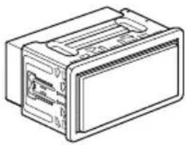
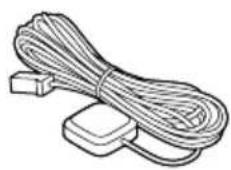
Partssupplied
natural_image
Line drawing of a rectangular electronic device with ports and casing (no text or symbols)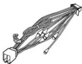
natural_image
Pure electrical circuit lines without any symbolsThisproductPowercord
natural_image
Illustration of a bundle of coiled cables and two separate electrical connectors (no text or symbols)
natural_image
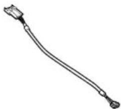
Illustration of a black cable with a connector and a mechanical clamp (no text or symbols)GPSaerialMicrophone

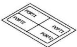
flowchart
graph TD
    A["PORT1"] --> B["PORT2"]
    B --> C["PORT3"]
    C --> D["PORT1"]
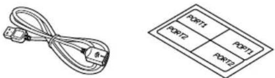
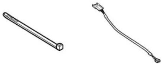
USBcableidentifica- tionlabels
USBcable (2pcs.)
natural_image
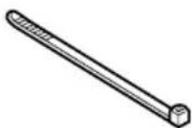
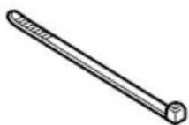
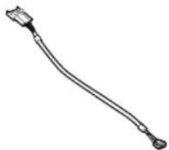
Line drawing of a cable or connector with a terminal connector (no text or symbols)Locktie*1 VehicleBusconversion cable*2

MetalsheetClamp(3pcs.)

Double-sidedtape

Notes
• (*1) These parts are supplied with AVIC-F88DAB.
• (*2) These parts are supplied with AVIC-F88DAB, AVIC-F80DAB and AVIC-F980DAB.
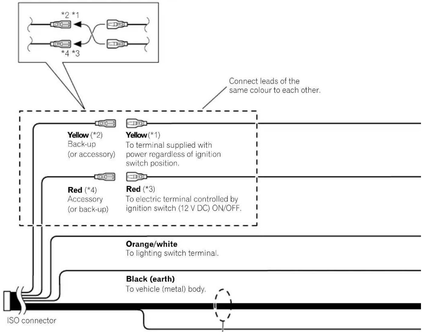
Connectingthepowercord(1)

Note
Depending on the types of vehicles, the function of *2 and *4 may be different. In this case, be sure to connect *1 to *4 and *3 to *2 as shown in the figure.
flowchart
graph TD
    A["ISO connector"] --> B["Yellow (*2)<br>Back-up<br>(or accessory)"]
    A --> C["Red (*4)<br>Accessory<br>(or back-up)"]
    A --> D["Orange/white<br>To lighting switch terminal."]
    A --> E["Black (earth)<br>To vehicle (metal) body."]
    B --> F["*2 *1"]
    B --> G["*4 *3"]
    C --> H["*1"]
    C --> I["*3"]
    style A fill:#f9f,stroke:#333
    note right of A Connect leads of the same colour to each other.
    note right of B Yellow(*1)
    note right of C Red(*3)
    note right of D Orange/white
    note right of E Black(earth)

Note
In some vehicles, the ISO connector may be divided into two. In this case, be sure to connect to both connectors.
Speaker leads
White: Front left ⊕
White/black: Front left ⊖
Grey: Front right ⊕
Grey/black: Front right ⊖
Green: Rear left ⊕
Green/black: Rear left ⊖
Violet: Rear right ⊕
Violet/black: Rear right ⊖
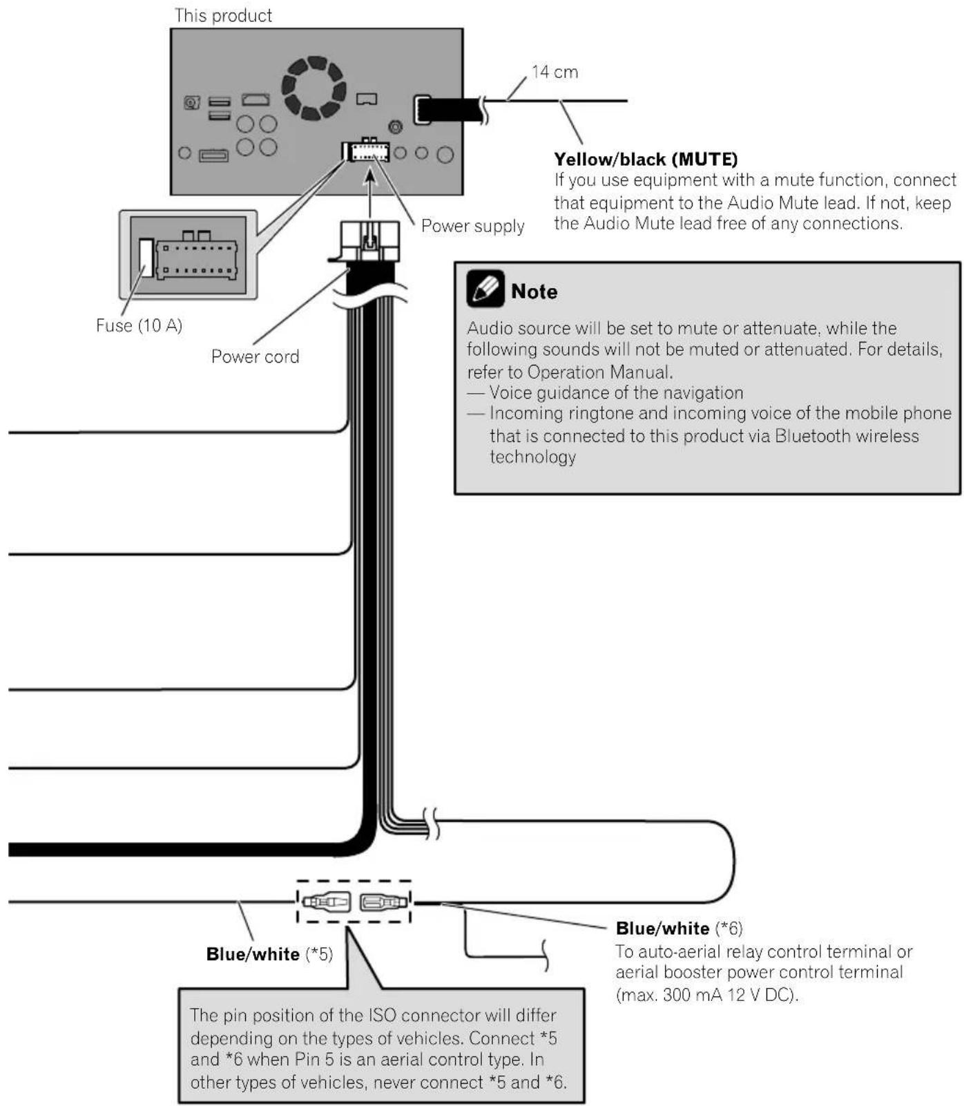

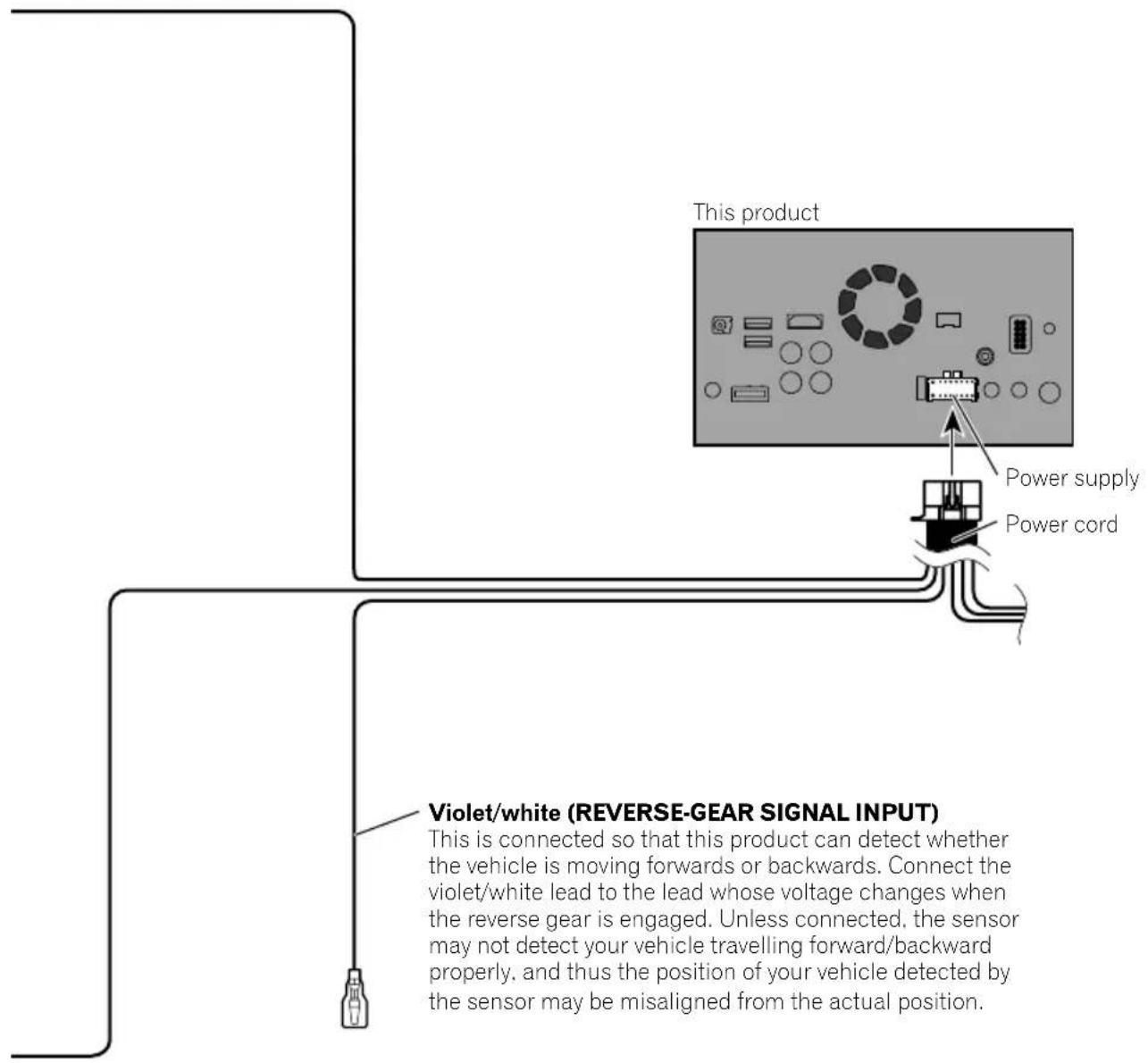
Connectingthepowercord(2)

Pink (CAR SPEED SIGNAL INPUT)
This product is connected here to detect the distance the vehicle travels. Always connect the vehicle's speed detection circuit. Failure to make this connection will increase errors in the vehicle's location display.

WARNING
IMPROPER CONNECTION MAY RESULT IN SERIOUS DAMAGE OR INJURY INCLUDING ELECTRICAL SHOCK, AND INTERFERENCE WITH THE OPERATION OF THE VEHICLE'S ANTILOCK BRAKING SYSTEM, AUTOMATIC GEARBOX AND SPEEDOMETER INDICATION.

CAUTION
It is strongly suggested that the speed pulse wire be connected for accuracy of navigation and better performance.

Note
The position of the speed detection circuit and the position of the handbrake switch vary depending on the vehicle model. For details, consult your authorised Pioneer dealer or an installation professional.
Light green (PARKING BRAKE)
Used to detect the ON/OFF status of the handbrake. This lead must be connected to the power supply side of the handbrake switch.
If this connection is made incorrectly or omitted, certain functions of this product will be unusable.

WARNING
LIGHT GREEN LEAD AT POWER CONNECTOR IS DESIGNED TO DETECT PARKED STATUS AND MUST BE CONNECTED TO THE POWER SUPPLY SIDE OF THE HANDBRAKE SWITCH. IMPROPER CONNECTION OR USE OF THIS LEAD MAY VIOLATE APPLICABLE LAW AND MAY RESULT IN SERIOUS INJURY OR DAMAGE.
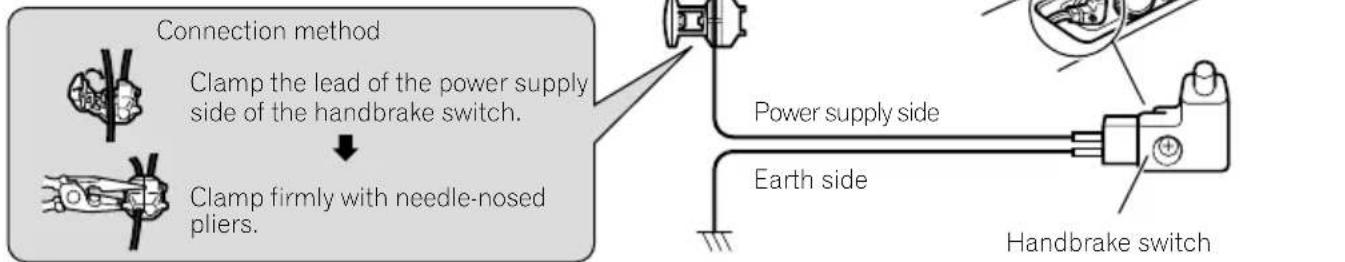
Connection

Note
When you use a rear view camera, please make sure to connect this lead. Otherwise you cannot switch to the rear view camera picture.

Connectingthesystem

WARNING
- To avoid the risk of accident and the potential violation of applicable laws, this product should never be used while the vehicle is being driven except for navigation purposes. And, also rear displays should not be in a location where it is a visible distraction to the driver.
- In some countries, the viewing of images on a display inside a vehicle even by persons other than the driver may be illegal. Where such regulations apply they must be obeyed and this product's video source should not be used.

Connectingtoseparatelysoldpoweramp
flowchart
graph TD
    A["Rear outputs (REAR OUTPUT)"] --> B["15 cm"]
    C["Front outputs (FRONT OUTPUT)"] --> D["This product"]
    E["Power amp (sold separately)"] --> F["Power amp (sold separately)"]
    G["White, Red (SWL, SWR)"] --> H["Power supply"]
    I["Power cord"] --> J["Power amp (sold separately)"]
    K["System remote control"] --> L["Subwoofer"]
    M["Front speaker"] --> N["+"]
    O["Rear speaker"] --> P["+"]
    Q["Power supply"] --> R["+"]
    S["Power cord"] --> T["+"]
    U["Power amp (sold separately)"] --> V["Power amp (sold separately)"]
    W["Power cord"] --> X["Power supply"]
    Y["Power supply"] --> Z["Power cord"]
    AA["Power supply"] --> AB["Power supply"]
    AC["Power supply"] --> AD["Power supply"]
    AE["Power supply"] --> AF["Power supply"]
    AG["Power supply"] --> AH["Power supply"]
    AI["Power supply"] --> AJ["Power supply"]
    AK["Power supply"] --> AL["Power supply"]
    AM["Power supply"] --> AN["Power supply"]
    AO["Power supply"] --> AP["Power supply"]
    AQ["Power supply"] --> AR["Power supply"]
    AS["Power supply"] --> AT["Power supply"]
    AU["Power supply"] --> AV["Power supply"]
    AW["Power supply"] --> AX["Power supply"]
    AY["Power amp (sold separately)"] --> Z
    AZ["Power amp (sold separately)"] --> AA
    BA["Power amp (sold separately)"] --> AB
    BB["Power amp (sold separately)"] --> AC
    BC["Power amp (sold separately)"] --> AD
    BD["Power amp (sold separately)"] --> AE
    BE --> AC
    BF["Power amp (sold separately)"] --> AG
    BG["Power amp (sold separately)"] --> AH
    BH["Power amp (sold separately)"] --> AI
    BI["Power amp (sold separately)"] --> AJ
    BJ["Power amp (sold separately)"] --> AK
    BK["Power amp (sold separately)"] --> AA
    BL["Power amp (sold separately)"] --> AB
    BM["Power amp (sold separately)"] --> AC
    BN["Power amp (sold separately)"] --> AD
    BO["Power amp (sold separately)"] --> AE
    BP["Power amp (sold separately)"] --> AA
    BQ["Power amp (sold separately)"] --> AB

Notes
- You can change the RCA output of the subwoofer depending on your subwoofer system. (Refer to Operation Manual.)
- The subwoofer output of this product is monaural.

ConnectinganiPod/iPhoneoranAndroiddevice
Findyourdeviceandthefunctionyouwanttooperatefromthelistbelow,andrefertothepagefortheconnection.
☐Dependingonthedevice, somefunctionsmaynotbeavailable.
| iPhone(5,5c,5s,6,6Plus)/iPodtouch(5thgeneration) | |
| iPod(audio)AppleCarPlayAVICSYNCApp | RefertoConnectingviatheUSBport(iPhone)onpage15. |
| AppRadioModeAVICSYNCApp | F88DABRefertoConnectingviatheHDMIport(iPhone)onpage16.F80DABF 980DAB F980BT F9880DAB F9880BTRefertoConnectingviatheRGBinput(iPhone)onpage16. |
| iPhone3GS/iPodtouch(2nd,3rdgeneration)/iPodclassic(80GB,160GB)/iPodnano(3rd,4th,5th,6thgeneration) | |
| iPod(audio)iPod(video) | RefertoConnectingviatheAUXinput(iPhone)onpage17. |
| iPhone(4,4s)/iPodtouch(4thgeneration) | |
| iPod(audio)iPod(video)AppRadioModeAVICSYNCApp | RefertoConnectingviatheRGBinput(iPhone)onpage18. |
| iPodnano(7thgeneration) | |
| iPod (audio) | Refer to Connecting via the USB port (iPhone) on page 15. |
| Androiddevice | |
| F88DABAppRadioMode | HDMIportRefertoConnectingviatheHDMIport(Androiddevice)onpage18.MHLport |
| AVICSYNCApp | RefertoConnectingviatheMHLport(Androiddevice)onpage19. |
| F88DAB AndroidAuto | RefertoConnectingviatheUSBport(Androiddevice)onpage19. |
| AVICSYNCApp | |

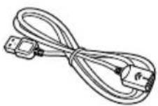
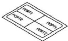
Attachingidentification labelstoUSBcables
AttachidentificationlabelstoUSBcablesbeforeinstallingthisproductinavehicle.
1ConnectUSBcablestotheUSBport1 and2ontherearofthisproduct.
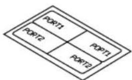
2AttachtheidentificationlabelscorrespondingtoeachporttotheUSBcablesas illustratedbelow.
Attachthe"PORT1"labeltotheUSBcable connectedtotheUSBport1. Attachthe"PORT2"labeltotheUSBcable connectedtotheUSBport2.

ConnectinganiPhonewith Lightningconnector

Notes
- Fordetailsonhowtoconnectanexternaldeviceusingaseparatelysoldcable, refertothe manualforthecable.
- Fordetailsconcerningtheconnection,operationsandcompatibilityofiPhone,refertoOperationManual.
ConnectingviatheUSBport (iPhone)
TheUSBinterfacecableforiPod/iPhone(CD-IU52)(soldseparately)isrequiredfortheconnection.
□WhenusingAppleCarPlay,connectthe iPhonetoUSBport1.
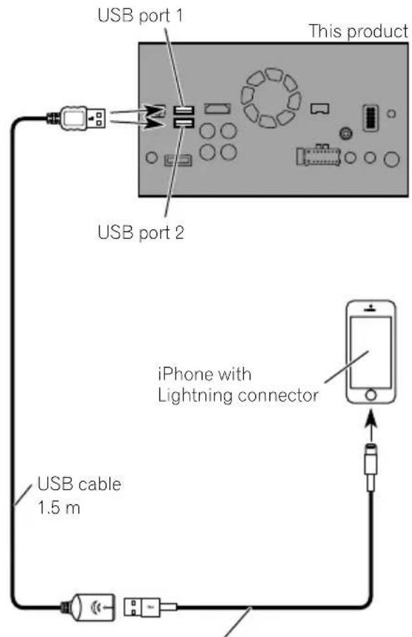
USB interface cable for iPod / iPhone (CD-IU52) (sold separately)
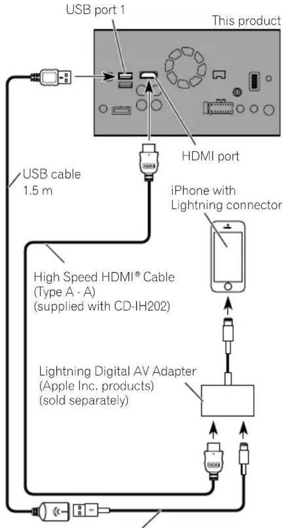
ConnectingviatheHDMIport (iPhone)
F88DAB
The following cablesarerequiredfortheconnection.
• HDMIinterfacecableforiPod/iPhone (CD-IH202)(soldseparately)
- USBinterfacecableforiPod/iPhone(CD-IU52)(soldseparately)
• LightningDigitalAVAdapter(AppleInc. products)(soldseparately)
flowchart
graph TD
    A["USB port 1"] --> B["This product"]
    C["USB cable 1.5 m"] --> D["HDMI port"]
    D --> E["iPhone with Lightning connector"]
    E --> F["High Speed HDMI® Cable (Type A - A) (supplied with CD-IH202)"]
    F --> G["Lightning Digital AV Adapter (Apple Inc. products) (sold separately)"]
    G --> H["Power Supply"]
    H --> I["External Portugal"]
USB interface cable for iPod / iPhone (CD-IU52) (sold separately)

Note
WhenyouconnecttheHighSpeedHDMI ^® Cable, usethelocktietofixitsecurely.
Fordetails, referto Securing the High Speed HDMI® Cableonpage20.
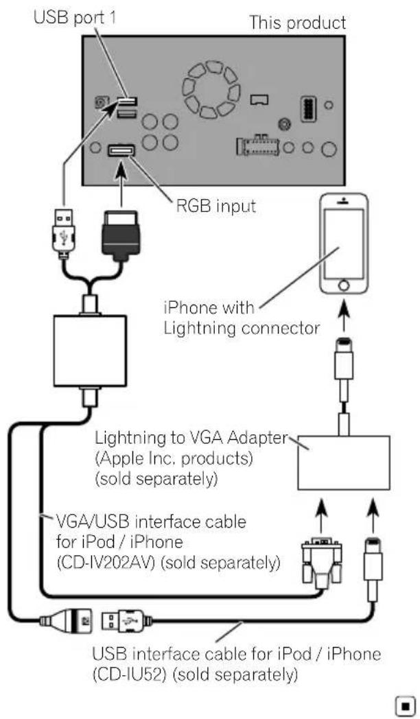
ConnectingviatheRGBinput (iPhone)
F80DABR
980DABF9
BOBT
F9880DAB
F9880BT
The following cablesarerequiredfortheconnection.
• VGA/USBinterfacecableforiPod/iPhone (CD-IV202AV)(soldseparately)
- USBinterfacecableforiPod/iPhone(CD-IU52)(soldseparately)
• LightningtoVGAAAdapter(AppleInc.products)(soldseparately)
flowchart
graph TD
    A["USB port 1"] --> B["RGB input"]
    B --> C["iPhone with Lightning connector"]
    C --> D["Lightning to VGA Adapter (Apple Inc. products) (sold separately)"]
    D --> E["VGA/USB interface cable for iPod / iPhone (CD-IV202AV) (sold separately)"]
    E --> F["USB interface cable for iPod / iPhone (CD-IU52) (sold separately)"]
    F --> G["Output"]
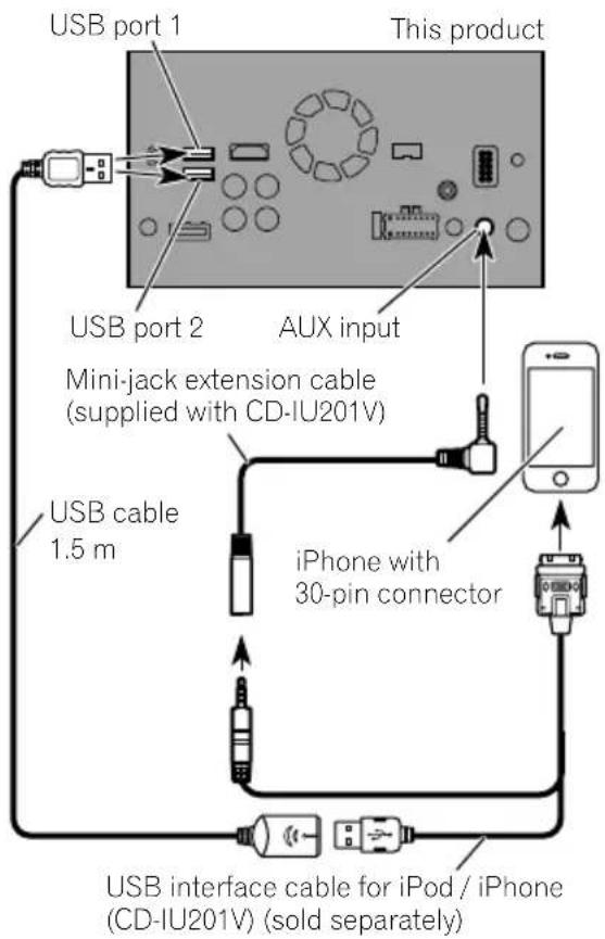
ConnectingviatheAUXinput (iPhone)
TheUSBinterfacecableforiPod/iPhone(CD-IU201V)(soldseparately)isrequiredforthe connection.
ConnectinganiPhonewith 30-pinconnector

Notes
- Fordetailsonhowtoconnectanexternaldeviceusingaseparatelysoldcable, refertothe manualforthecable.
- Fordetailsconcerningtheconnection,operationsandcompatibilityofiPhone,refertoOperationManual.
ConnectingviatheRGBinput (iPhone)
TheUSBinterfacecableforiPod/iPhone(CD-IU201S)(soldseparately)isrequiredforthe connection.
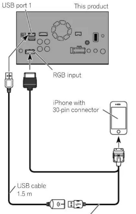
USB interface cable for iPod / iPhone (CD-IU201S) (sold separately)

ConnectingtheAndroid ^TM device
F88DAB
AppConnectivityKit(CD-AH200)(soldseparately)isrequiredfortheconnection.

Notes
- Fordetailsonhowtoconnectanexternaldeviceusingaseparatelysoldcable, refertothe manualforthecable.
- FordetailsconcerningtheconnectionandoperationsofAndroiddevice,refertoOperation Manual.
- WhenyouconnecttheHighSpeedHDMI Cable, usethelocktietofixitsecurely.
Fordetails, refer to Securing the High Speed HDMI ^® Cable on page 20.
ConnectingviatheHDMIport (Androiddevice)
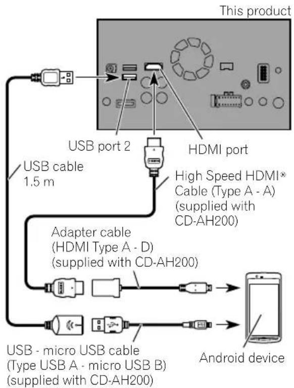
flowchart
graph TD
    A["This product"] --> B["USB port 2"]
    B --> C["HDMI port"]
    C --> D["High Speed HDMI® Cable (Type A - A) (supplied with CD-AH200)"]
    D --> E["Adapter cable (HDMI Type A - D) (supplied with CD-AH200)"]
    E --> F["Android device"]
    F --> G["USB - micro USB cable (Type USB A - micro USB B) (supplied with CD-AH200)"]
    G --> H["USB cable 1.5 m"]
ConnectingviatheMHLport (Androiddevice)
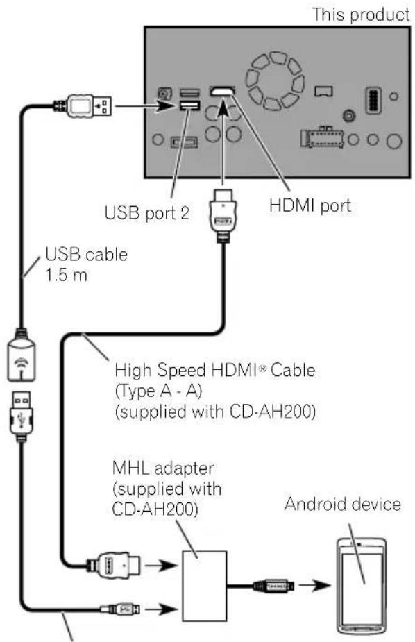
flowchart
graph TD
    A["This product"] --> B["USB port 2"]
    A --> C["HDMI port"]
    B --> D["USB cable 1.5 m"]
    C --> D
    D --> E["High Speed HDMI® Cable (Type A - A) (supplied with CD-AH200)"]
    E --> F["MHL adapter (supplied with CD-AH200)"]
    F --> G["Android device"]
    G --> H["Mobile Device"]
USB - micro USB cable
(Type USB A - micro USB B)
(supplied with CD-AH200)
TheUSBinterfacecableforusewithAndroid devices(CD-MU200)(soldseparately)isrequiredfortheconnection.
ConnectingviatheUSB port(Androiddevice)
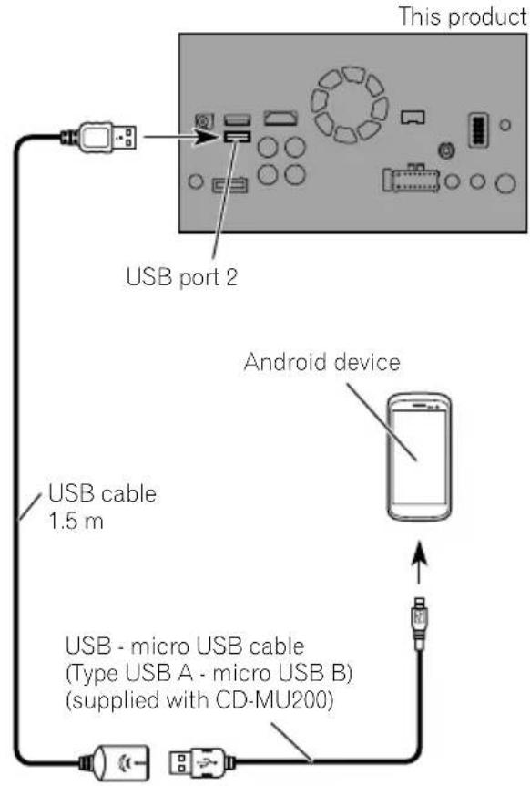


Note
Fordetailsonhowtoconnectanexternaldevice usingaseparatelysoldcable, refertothemanual forthecable.
SecuringtheHighSpeed HDMI® Cable
F88DAB
BesuretofixtheHighSpeedHDMI ^® Cable withthelocktie,whenyouconnecttheexternaldevicewiththeHighSpeedHDMI ^® Cable.
1InserttheHighSpeedHDMI® Cableinto theHDMIport.
2Wrapthelocktiearoundthehook abovetheHDMIportandtheHighSpeed HDMI® Cable, andthentightenittosecure theHighSpeedHDMI ® Cable.
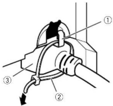
①Hook
②Locktie
③HighSpeedHDMI ^® Cable
□Donottightenupthelocktiemorethan necessary.
Connectingarearviewcamera
Whenthisproductisusedwitharearview camera,itispossibletoautomaticallyswitch fromthevideotorearviewimagewhenthe gearstickismovedtoREVERSE(R).Camera Viewmodealsoallowsyoutocheckwhatis behindyouwhiledriving.

WARNING
USEINPUTONLYFORREVERSEORMIRROR IMAGEREARVIEWCAMERA.OTHERUSEMAY RESULTININJURYORDAMAGE.

CAUTION
- Thescreenimagemayappearreversed.
- Therearviewcameraisusedasanaidto keepaneyontrailers,orbackingintoatight parkingspot.Donotusethisfunctionforen- tertainmentpurposes.
- Objectsinrearviewmayappearcloseror moredistantthaninreality.
- Plesenotethattheimageareashownbythe rearviewcameramaydifferslightlywhenfull-screenimagesaredisplayedwhenbacking andwhencheckingtherearofthevehicle whilemovingforward.
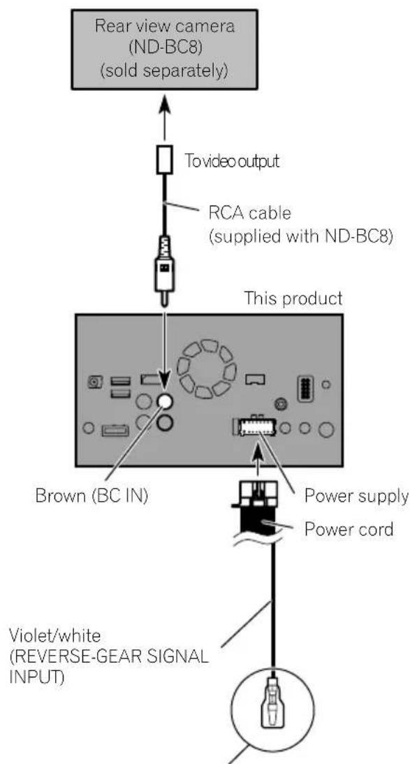
flowchart
graph TD
    A["Rear view camera (ND-BC8) (sold separately)"] --> B["To video output"]
    B --> C["RCA cable (supplied with ND-BC8)"]
    C --> D["This product"]
    D --> E["Brown (BC IN)"]
    E --> F["Power supply"]
    E --> G["Power cord"]
    F --> H["Violet/white (REVERSE-GEAR SIGNAL INPUT)"]
    G --> I["Output"]
Formoredetailsaboutthewiring,refertoConnecting thepowercord(2)onpage10.

Notes
- Thismodeisavailablewhentherearview camerasettingissetto"On".(Fordetails, refertoOperationManual.)
- Connectthisproducttotherearviewcamera only.Donotconnecttoanyother equipment.
Connectingtheexternal videocomponent
UsingAVinput
Youcanconnectanexternalvideocomponent orexternalcameratothisproduct.
Connectinganexternalcamera
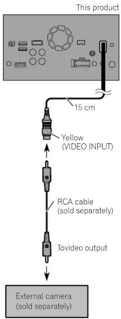

Note
ThismodeisavailablewhenthesettingofAV inputissetto"Camera".(Fordetails,refertoOperationManual.)
Connectingthevideocomponent
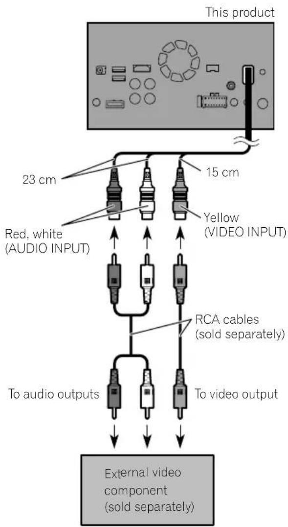

Note
This mode is available when the setting of AV input is set to "Source". (For details, refer to Operation Manual.)
UsinganAUXinput
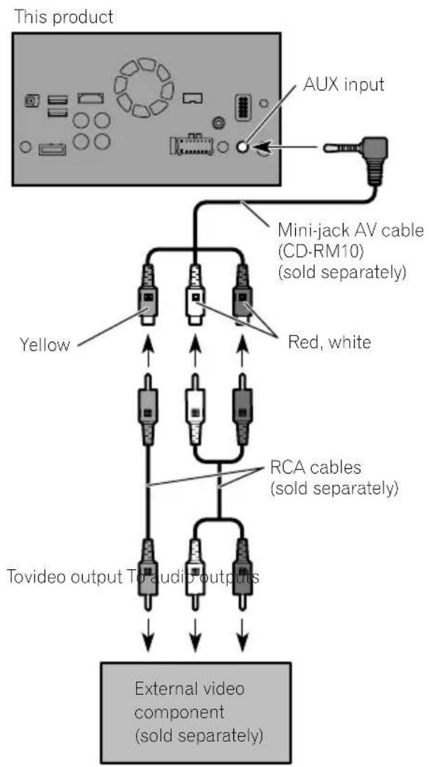
flowchart
graph TD
    A["This product"] --> B["AUX input"]
    B --> C["Mini-jack AV cable (CD-RM10) (sold separately)"]
    C --> D["Yellow"]
    C --> E["Red, white"]
    C --> F["RCA cables (sold separately)"]
    F --> G["Tovideo output TO audio outputs"]
    G --> H["External video component (sold separately)"]

Notes
- This mode is available when the setting of AUX input is set to "On". (For details, refer to Operation Manual.)
- When connecting an external video component using a mini-jack AV cable, use a separately sold AUX extension cable as necessary.

CAUTION
Besuretouseamini-jackAVcable(CD-RM10) (soldseparately)forwiring.Ifyouuseother cables,thewiringpositionmightdifferresulting indisturbedimagesandsounds.
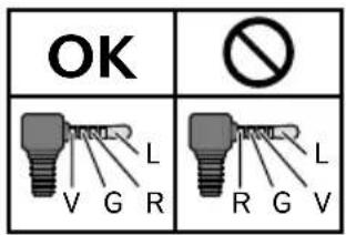
L: Left audio (White)
R : Right audio (Red)
V: Video (Yellow)
G: Earth

ConnectinganHDMIdevice
F88DAB
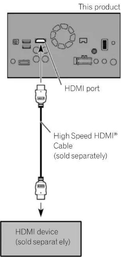

Notes
- FordetailsconcerningtheoperationsofHDMI device,refertoOperationManual.
- WhenyouconnecttheHighSpeedHDMI Cable, usethelocktietofixitsecurely.
Fordetails, referto Securing the High Speed HDMI ^® Cable on page 20.

Connectingthereardisplay
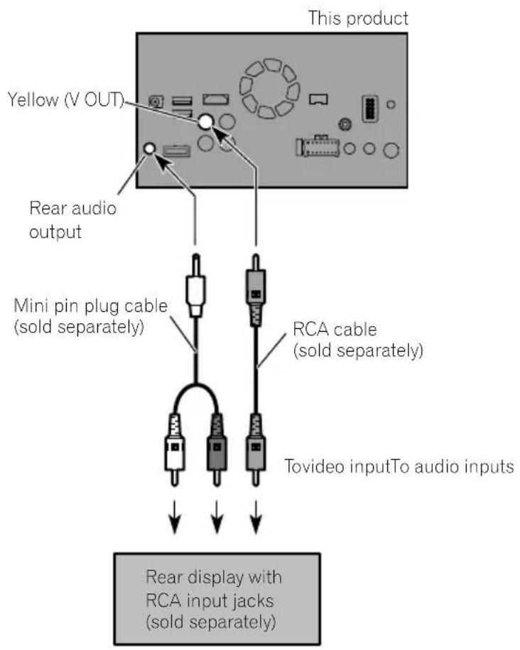
When using areardisplay connected to rear video output

WARNING
NEVERinstallthereardisplayinalocation that enable sthedrivertowatchthevideo sourcewhiledriving.
Thisproduct'srearvideooutputisforconnection ofadisplaytoenablepassengersintherear seatstowatchthevideosource.
Precautionsbefore installation

CAUTION
- Neverinstallthisproductinplaceswhere, orinamannerthat:
—Could injurethedriverorpassengersif thevehiclestopssuddenly.
—Mayinterferewiththedriver'soperationofthevehicle,suchasonthefloorinfrontofthedriver'sseat,orclosetothesteeringwheelorgearstick. - Makesurethereisnothingbehindthe dashboardorpanellingwhendrilling holesinthem.Becarefulnottodamage fuellines,brakelines,electroniccomponents,communicationwiresorpower cables.
- Whenusingscrews, donotallowthemto comeintocontactwithanyelectricallead. Vibrationmaydamagewiresorinsulation, leadingtoashortcircuitorotherdamage tothevehicle.
- Toensureproperinstallation,besureto usethesuppliedpartsinthemannerspecified.Ifanypartsarenotsuppliedwith thisproduct,usecompatiblepartsinthe mannersspecifiedafteryouhavetheparts' compatibilitycheckedbyyourdealer.If partsotherthansuppliedorcompatible onesareused,theymaydamageinternal partsofthisproductortheymaywork looseandtheproductmaybecomedetached.
- Itisextremelydangeroustoallowcables tobecomewoundaroundthesteeringcolumnorgearstick.Besuretoinstallthis product,itscables,andwiringawayin suchsothattheywillnotobstructorhinderdriving.
- Makesurethatleadscannotgetcaughtin adoorortheslidingmechanismofaseat, resultinginashortcircuit.
-
Please confirm the proper function of your vehicle's other equipment after installation of this product.
-
Donotinstallthisproductwhereitmay(i) obstructthedriver'svision,(ii)impairthe performanceofanyofthevehicle'soperatingsystemsorsafetyfeatures,includingairbags,hazardlampbuttonsor(iii)impairthedriver'sabilitytosafelyoperatethevehicle.
- Install this product between the driver's seat and front passenger seat so that it will not be hit by the driver or passenger if the vehicle stops quickly.
- Neverinstallthisproductinfrontofor nexttotheplaceinthedashboard,door, orpillarfromwhichhoneofyourvehicle's airbagswoulddeploy.Pleaserefertoyour vehicle'sowner'smanualforreferenceto thedeploymentareaofthefrontalairbags.
- Failuretofollowalloftheseprecautions mayresultinserious injuryordeath.
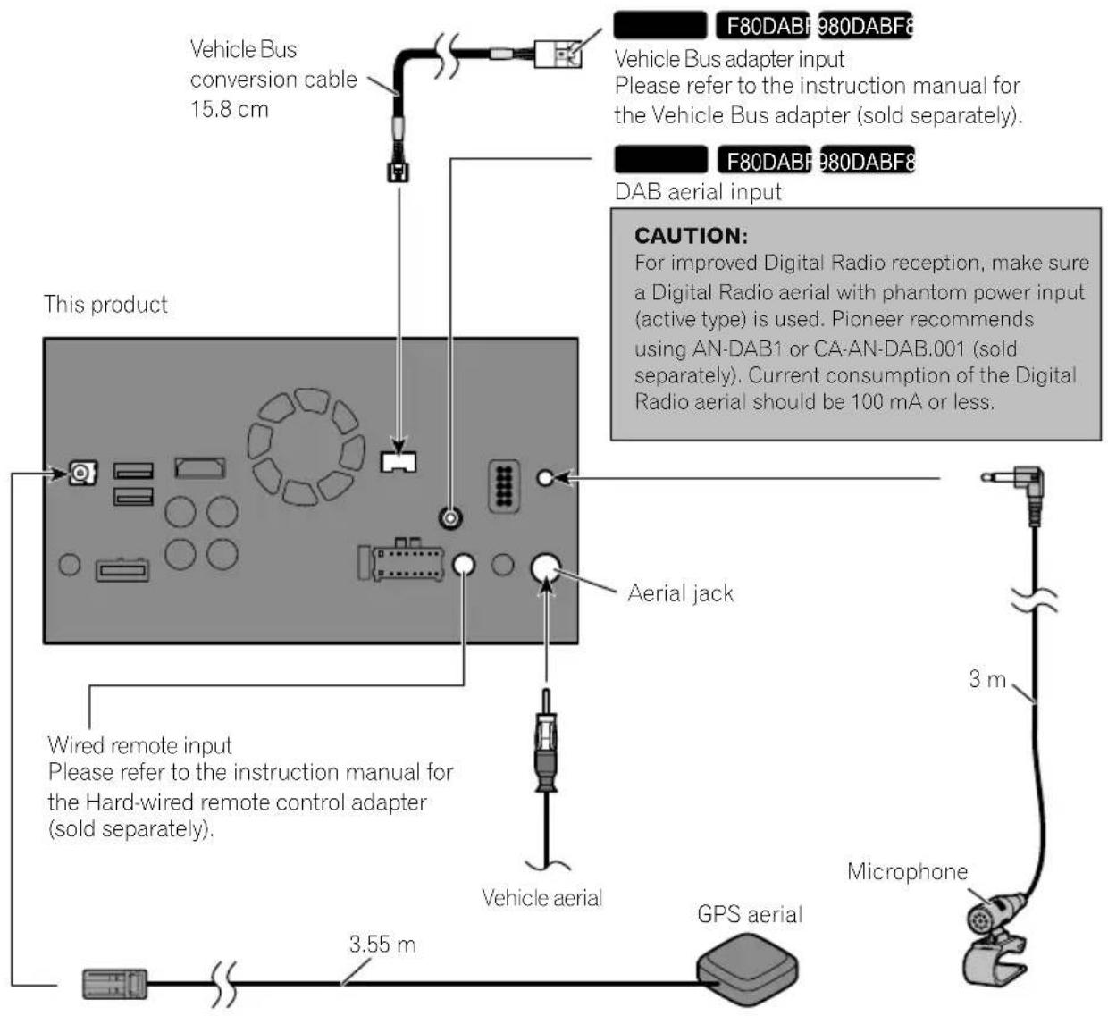
Toavoidelectromagnetic interference
Inordertopreventinterference, setthefollowingitemsasfaraspossiblefromthisproduct, othercablesorleads:
• FM, MW/L Waerialanditslead
- DABaerialanditslead(forAVIC-F88DAB, AVIC-F80DABandAVIC-F980DAB)
- GPSaerialanditslead Inaddition,youshouldlayorrouteeachaerial leadasfaraspossiblefromotheraerialleads. Donotbind,layorrouetethemtogether,or crossthem.Electromagneticnoisewillin- creasethepotentialforerrorsinthevehicle's locationdisplay.
Beforeinstalling
- Consultwithyournearestdealerifinstallationrequiresdrillingholesorothermodificationsofthevehicle.
- Beforemakingafinalinstallationofthis product, temporarilyconnectthewiringto confirmthattheconnectionsarecorrect andthesystemworksproperly.
ForAVIC-F88DABandAVIC-F80DABusers
Donotinstallthisproductinapositionwhere theopeningoftheLCDpanelisobstructedby anyobstacles,suchasthegearstick.Before installingthisproduct,besuretoleavesufficientspacesothattheLCDpaneldoesnotobstructthegearstickwhenitisfullyopened. Thismaycauseinterferencewiththegearstick,oramalfunctionofthemechanismof thisproduct.
Installingthisproduct Installationnotes
- Donotinstallthisproductinplacesubject toighttemperaturesorhumidity,suchas:
—Placesclosetoaheater,ventorairconditioner.
—Placesexposedtodirectsunlight,such asontopofthedashboard.
—Placesthatmaybeexposedtorain, suchasclosetothedoororonthevehicle'sfloor.
• Install this product in an area a strongen-ought bearits weight. Choose a position where this product can be firmly installed, and install it securely. If this product is not securely installed, the current location of the vehicle cannot be displayed correctly.
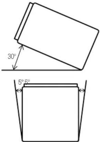
• Install this product horizontally on asurface within 0 to 30 degrees tolerance (within 5 degrees the left or right). Improper installation of the product with the surface tilted more than these tolerances increases the potential for errors in the vehicle's location display, and might otherwise cause reduced display performance.
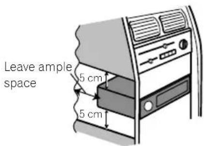
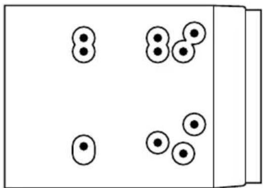
- Wheninstalling,toensureproperheatdispersalwhenusingthisproduct,makesure youleaveamplespacebehindtherear panelandwrapanyloosecablessothey arenotblockingthevents.
Installation
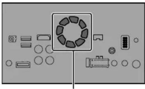
- Thecordsmustnotcovertheareashown inthefigurebelow. This is necessary to allow the amps and navigation mechanism to dissipate heat.
natural_image
Top-down view of a device layout with circular components and connectors (no text or symbols)Donotcoverthisarea.
- These semiconductor laser will be damaged if to overheats, sodon't install this product anywhere—for instance, near a heater outlet.
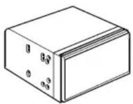
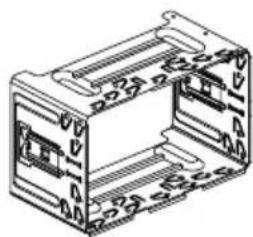
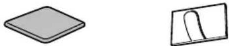
Partssupplied
Partsmarked(*)arepre-installed.
natural_image
Simple line drawing of a rectangular block with four small circular holes on its faces (no text or symbols)ThisproductHolder*
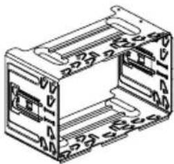
natural_image
Isometric line drawing of a mechanical housing or enclosure with mounting holes and internal compartments (no text or symbols)
Trussheadscrew (5mm×8mm) (6pcs.)
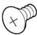
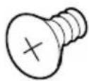
Flushsurfacescrew (5mm×9mm) (6pcs.)
natural_image
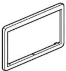
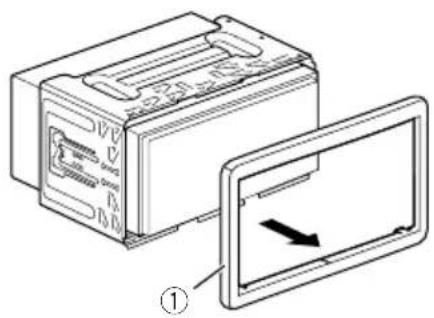
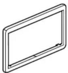
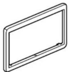
Simple line drawing of a rectangular frame with rounded corners and a central horizontal bar (no text or symbols)Trimring*ExtractionKey
(2pcs.)
Beforeinstallingthisproduct
1Removethetrimring.
Extendtopandbottomofthetrimringoutwardstoremovethetrimring.
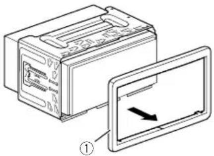
①Trimring
2Insertthesuppliedextractionkeysinto bothsidesoftheunituntiltheyclickinto place.
3Pulltheunitoutoftheholder.
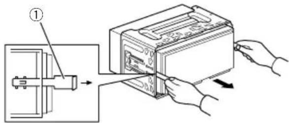
①Extractionkey
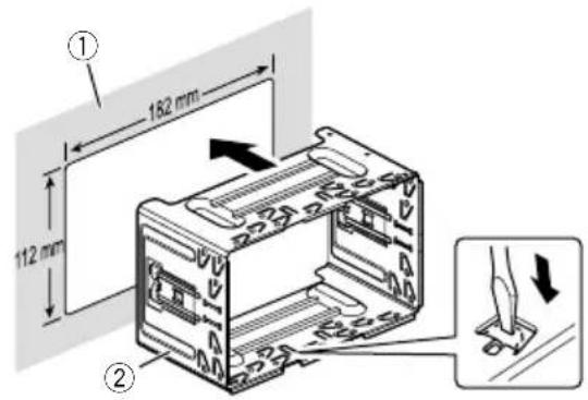
Installationwiththeholder
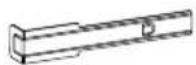
1Installtheholderintothedashboard.
2Securethemountingsleevebyusinga screwdrivertobendthemetaltabs(90°) intoplace.
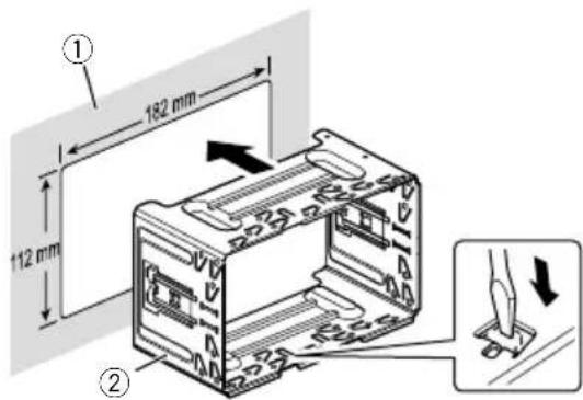
① Dashboard
②Holder
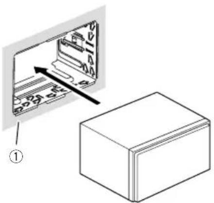
3Installthisproductintotheholder.
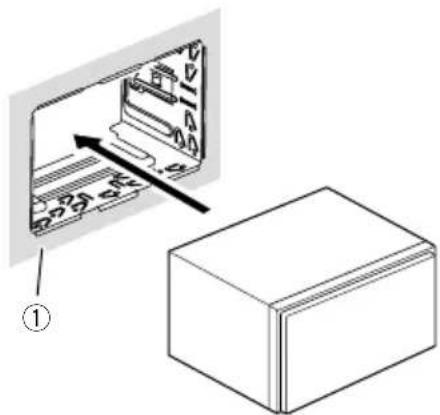
①Dashboard
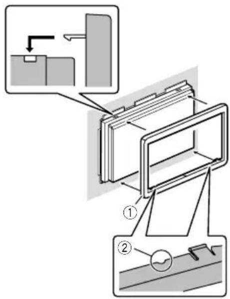
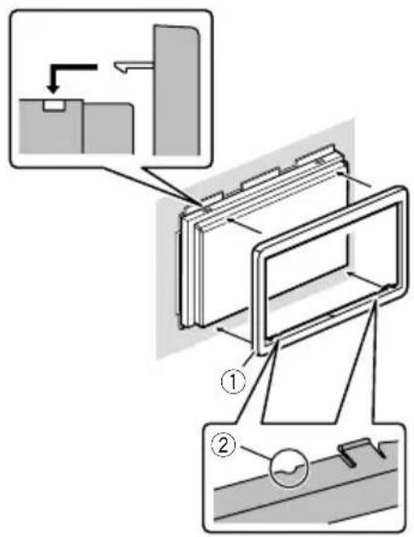
4Attachthetrimring.
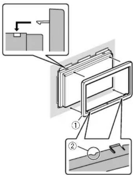
①Trimring
②Groove
Attachthetrimringwiththesidewitha groovefacingdownward.
Installationusingthescrew holesonthesideofthisproduct
●Fasteningthisproducttothefactory radio-mountingbracket.
Positionthisproductsothatitsscrewholes arealignedwiththescrewholesofthebracket,andtightenthescrewsatthreelocations oneachside.
Use either the truss head screw (5mm × 8mm) or flush surfaces screw (5mm × 9mm), depending on the shape of the bracket's screw holes.
natural_image
Simple diagram of five circles arranged in two groups, one larger and three smaller, with no text or symbols present.If the pawl interferes with installation, you may bend it down out of the way.
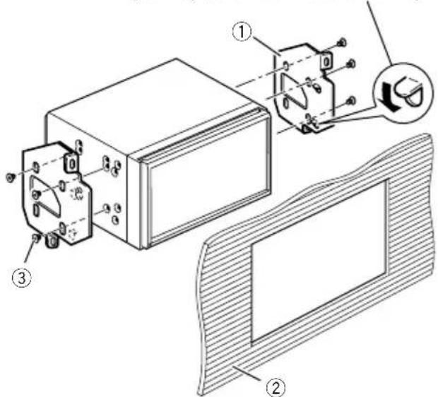
①Factoryradio-mountingbracket
② Dashboardorconsole
③Trussheadscreworflushsurfacescrew Besuretousethescrewssuppliedwith thisproduct.
InstallingtheGPSaerial
CAUTION
DonotcuttheGPSaerialleadtoshortenit oruseanextensiontomakeitlonger. Alteringtheaerialcablecouldresultinashortcircuitormalfunctionandpermanentdamage tothisproduct.
Installationnotes
- Theaerialshouldbeinstalledonalevelsurfacewhereradiowaveswillbeblockedas littleaspossible.Radiowavescannotbereceivedbytheaerialifreceptionfromthesatelliteisblocked.
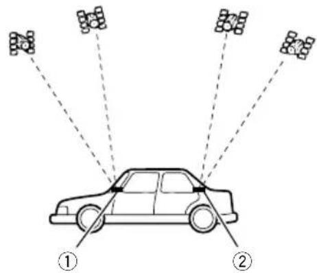
① Dashboard
②Rearshelf
- WheninstallingtheGPSaerialinsidethe vehicle,besuretousethemetalsheetprovidedwithyoursystem.Ifthisisnotused,thereptionsensitivitywillbepoor.
- Donotcuttheaccessorymetalsheet. This would reduce cethesensitivity of the GPS aerial.
•Takecarenottopulltheaerialleadwhen removingtheGPSaerial.Theleadmaybe-comedetached. - DonotpainttheGPSaerial, asthismayaffectitsperformance.
Wheninstallingtheaerialinsidethevehicle(onthedashboardor rearshelf)

WARNING
DonotinstalltheGPSaerialoveranysensorsorventsonthedashboardofthevehicle, asdoingsomayinterferewiththeproper functioningofsuchsensorsorventsandmay compromisetheabilityofthemetalsheet undertheGPSaerialtoproperlyandsecurelyaffixtothedashboard.
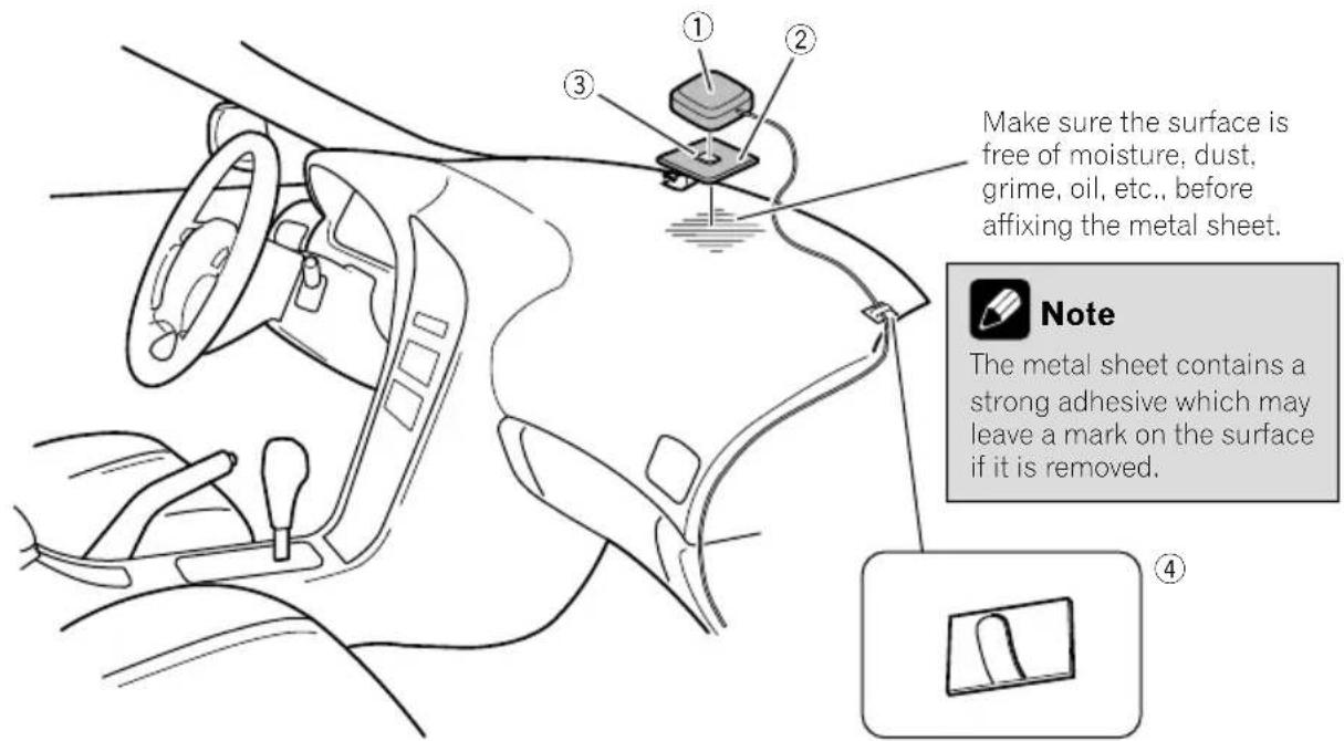
①GPSaerial
②Metalsheet
Peelofftheprotectivesheetontherear.
③Double-sidedtape
④Clamps
Useclampstosecuretheleadwherenecessaryinsidethevehicle.
Affixthemetalsheetonthesurfaceaslevelas possiblewheretheGPSaerialfacesthewindow.AffixtheGPSaerialonthemetalsheet usingthedouble-sidedtape.

Notes
- Whenattachingthemetalsheet, donotcut itintosmallpieces.
- Somemodelsusewindowglassthatdoes notallowsignalsfromGPSsatellitesto passthrough.Onsuchmodels,installthe GPSaerialontheoutsideofthevehicle.

Installation
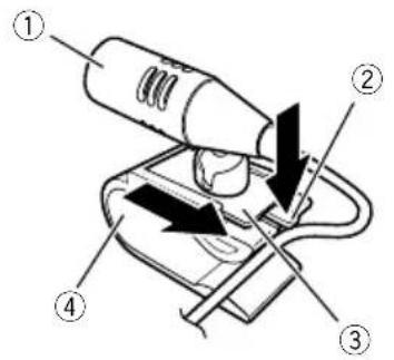
Installingthemicrophone
• Install themicrophone in a place where its direction and distance from the driver make it easiest to pickup the driver's voice.
- Besuretoturnoff(ACCOFF)theproduct beforeconnectingthemicrophone.
- Dependingonthevehiclemodel,themicrophonecablelengthmaybetooshort whenyoumountthemicrophoneonthe sunvisor.Insuchcases,installthemicrophoneonthesteeringcolumn.
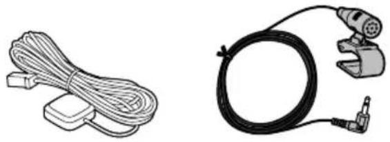
Partssupplied
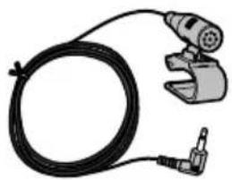
natural_image
Illustration of a handheld electric shaver connected to a black cable (no text or symbols)
MicrophoneDouble-sidedtape
Mountingonthesunvisor
1Fitthemicrophoneleadintothe groove.
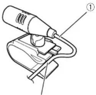
②
①Microphonelead
②Groove
2Attachthemicrophonecliptothesun visor.
①Microphoneclip
②Clamps
Useseparatelysoldclampstosecurethe leadwherenecessaryinsidethevehicle.
Install themicrophone on the sunvisor when it is in the up position. It cannot recognise the driver's voice if the sunvisor is in the down position.
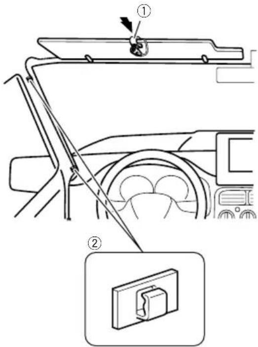
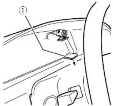
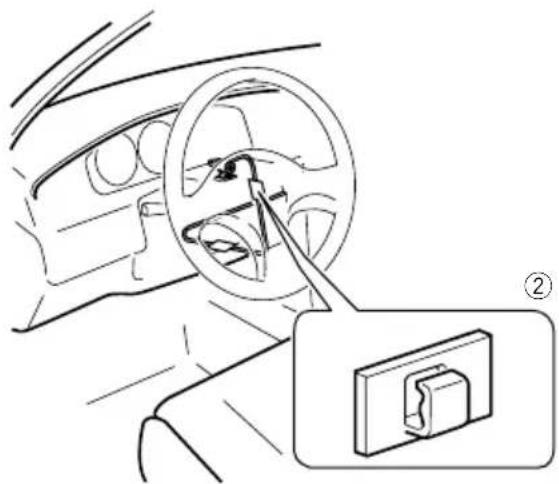
Installationonthesteeringcolumn
1 Detachthemicrophonebasefrom the microphoneclipbyslidingthemicrophone basewhilepressingthetab.
①Microphone
②Tab
③Microphonebase
④Microphoneclip
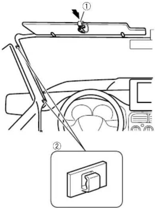
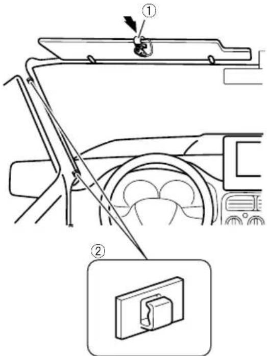
2Mountthemicrophoneonthesteering column.
Installthemicrophoneonthesteeringcolumn,keepingitawayfromthesteeringwheel.
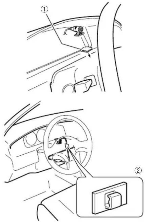
①Double-sidedtape
②Clamps
Useseparatelysoldclampstosecurethe leadwherenecessaryinsidethevehicle.
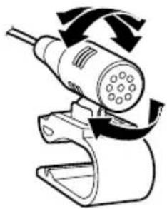
Adjustingthemicrophoneangle
Themicrophoneanglecanbeadjusted.
natural_image
Diagram of a handheld device with rotating arrows indicating motion (no text or symbols)
Afterinstallation
Afterinstallingthisproduct
1Reconnectthenegative(−)terminalof thevehicle'sbattery.
First, double-check that all connections are correct and that this product is installed correctly. Reassemble all vehicle components that you previously removed. Then reconnect then negative(−) cable to then negative(−) terminal of the battery.
2Starttheengine.
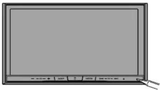
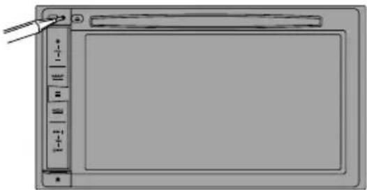
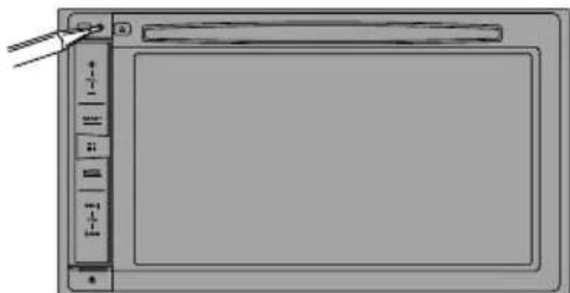
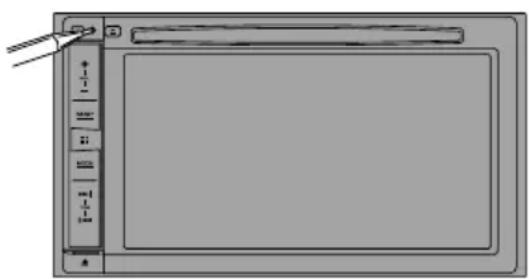
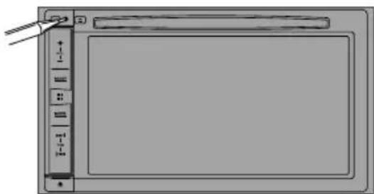
3PresstheRESETbutton.
PresstheRESETbuttononthisproductwitha pointedobjectsuchasthetipofapen.
F88DABF30DAB
natural_image
Front view of a blank computer monitor with control buttons and a mouse pointer (no text or symbols on screen)F980DABF980BT F9880DAB F9880BT
natural_image
Illustration of a blank digital drawing tablet with control panel and scroll bar (no text or symbols)Someofthesettingsandrecordedcontents willnotbereset.
4Changethesettingsasdesired.
- Fordetailsconcerningoperations,referto OperationManual.
5 Drivedownanunobstructedroaduntil theGPSstartsreceivingthesignalnormally.

Note
Afterinstallingthisproduct,besuretocheckata safeplacethatthevehicleisperformingnormally.
01 Précautions
Installationdumicrophone64
-Piècesfournies64
-Installationsurlepare-soleil64
- Installationsurlacolonnede direction65
-Réglagedel'angledumicrophone65
natural_image
Illustration of a hand holding a battery with wires and a pointer, no text or symbols present

PositionACCPasdeposition
ACC
natural_image
Technical line drawing of a device with a rectangular box and a wire-wrapped electrical connector (no text or symbols)natural_image
Two types of electronic devices: a wire with plug and socket, and a black cable with connector (no text or symbols visible)AntenneGPSMicrophone
natural_image
Two technical diagrams: one showing a cable with connector, the other showing a labeled grid layout (no text or symbols present)natural_image
Two technical line drawings of mechanical components: a cylindrical rod and a curved cable with connectors (no text or symbols)natural_image
Two simple 3D geometric shapes: a gray square and a white rectangular outline (no text or symbols)natural_image
Top-down view of a device layout with circular components and connectors (no text or symbols)natural_image
Isometric view of a rectangular block with four small circular holes on its faces (no text or symbols)CeproduitSupport*
natural_image
Isometric line drawing of a mechanical housing or enclosure with no visible text or symbolsnatural_image
Simple line drawing of a rectangular frame with a horizontal bar at the bottom (no text or symbols)1Retirezl'anneaudegarniture.
Étirezversl'extérieurlapartiesupérieureetinférieuredel'anneaudegarniturepourleretirer.
①Anneaudegarniture
①Clédédémontage
Installationaveclesupport
1Installezlesupportsurletableaude bord.
2Fixezlemanchondemontageenutilisantuntournevispourcourberlespattes métalliques(90°)enplace.
①Tableaudebord
②Support
3Installezceproduitdanslesupport.
①Tableaudebord
4Attachezl'anneaudegarniture.
①Anneaudegarniture
②Fente
natural_image
Diagram showing six black dots arranged in four groups within a rectangular frame (no text or symbols)Installationdumicrophone
natural_image
Illustration of a cable with a connector and a separate rectangular device (no text or symbols)Microphone Bandeadhésiveà doubleface
Installationsurlepare-soleil
①Fildumicrophone
②Fente
2Fixezl'agrafepourmicroaupare-soleil.
①Microphone
②Languette
③Basedumicrophone
④Agrafepourmicro
2Montezlemicrophonesurlacolonne dedirection.
Installezlemicrophonesurlacolonnededirection,àdistanceduvolant.

natural_image
Interior view of a car showing steering wheel and dashboard with a close-up inset of the dashboard (no text or symbols)natural_image
Diagram of a handheld electric shaver with rotating arrows indicating rotation (no text or symbols)
natural_image
Front view of a blank computer monitor with control buttons and a pointing cursor (no text or symbols on the screen)F980DABF 980BT F9880DAB F9880BT
natural_image
Diagram of a digital tablet device with control panel and scroll bar (no text or symbols)natural_image
Illustration of a hand holding a battery with a pliers, no text or symbols present
Perevitaredanni

AVVERTENZA

natural_image
Line drawing of a rectangular electronic device with ports and a central screen (no text or symbols)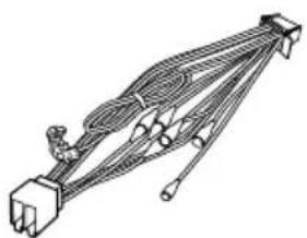
natural_image
Technical line drawing of a mechanical linkage or connector assembly (no text or symbols)natural_image
Illustration of a black cable with a connector and a mechanical clamp (no text or symbols)AntennaGPSMicrofono
flowchart
graph TD
    A["PORT1"] --> B["PORT2"]
    B --> C["PORT1"]
    C --> D["PORT2"]
Etichetteidentificative delcavoUSB
CavoUSB (2pezzi)
natural_image
Simple line drawing of a curved mechanical or electrical component (no text or symbols)Cavodiconversione Busperveicolo*2
natural_image
Top-down view of a device layout with circular components and a central circular component (no text or symbols)natural_image
Isometric view of a rectangular block with four small circular holes on its faces (no text or symbols)natural_image
Isometric line drawing of a rectangular electronic component housing (no text or symbols)
Viteatestatonda (5mm×8mm) (6pezzi)

Viteatestapiatta (5mm×9mm) (6pezzi)
natural_image
Simple line drawing of a rectangular frame with rounded corners and a central hole (no text or symbols)①Cornicedifinitura
①Chiavediestrazione
①Cruscotto
natural_image
Simple diagram of six circles arranged in two groups, one larger and one smaller, with no text or symbols present.①Cruscotto
natural_image
Illustration of a handheld electronic device with cable and connector, next to a separate rectangular component (no text or symbols)②
①Cavodelmicrofono
②Fessura
natural_image
Diagram of a car interior showing steering wheel and dashboard, with a close-up inset of the dashboard component (no text or symbols)natural_image
Diagram of a handheld device with rotating arrows indicating motion (no text or symbols)
natural_image
Front view of a blank computer monitor with control buttons and a cursor pointer (no visible text or symbols on the screen)F980DABF 980BT F9880DAB F9880BT
natural_image
Front view of a blank digital tablet device with control buttons and a scroll (no text or symbols visible)natural_image
Illustration of a hand holding a battery with a pliers, showing the switch and battery terminals (no text or symbols)
Paraimpedirdaños

ADVERTENCIA

natural_image
Line drawing of a rectangular electronic device with ports and a central screen (no text or symbols)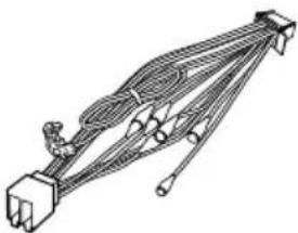
natural_image
Technical line drawing of a mechanical linkage or connector assembly (no text or symbols)natural_image
Illustration of a black cable with a connector and a mechanical clamp (no text or symbols)AntenaGPSMicrófono

flowchart
graph TD
    A["PORT1"] --> B["PORT2"]
    B --> C["PORT1"]
    C --> D["PORT2"]
natural_image
Line drawing of a curved mechanical or electrical component with no visible text or symbolsnatural_image
Top-down view of a device layout with circular components and a central square (no text or symbols)Nocubraestazona.
natural_image
Simple line drawing of a rectangular box with four small circular holes on its sides (no text or symbols)natural_image
Technical line drawing of a mechanical component housing (no text or symbols)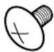
Tornillodecabezasegmentada (5mm×8mm) (6piezas)
Tornillodesuperficie plana (5mm×9mm) (6piezas)
natural_image
Simple line drawing of a rectangular frame with rounded corners and a central hole (no text or symbols)①Anilloembellecedor
①Llavedeextracción
①Tablerodeinstrumentos
4Coloqueelanilloembellecedor.

①Anilloembellecedor
②Ranura
natural_image
Simple diagram of five circles arranged in two groups within a rectangular frame (no text or symbols)①Tablerodeinstrumentos
②Bandejatrasera
natural_image
Illustration of a cable with a connector and a separate electrical outlet (no text or symbols)①Cabledelmicrófono
②Ranura
2Fijeelclipdelmicrófonoalparasol.

natural_image
Diagram of a car interior showing steering wheel and dashboard, with a close-up inset of the dashboard component (no text or symbols)natural_image
Diagram of a handheld device with rotating arrows indicating motion (no text or symbols)
natural_image
Front view of a blank computer monitor with control buttons and a scroll (no text or symbols on screen)F980DABF 980BT F9880DAB F9880BT
natural_image
Diagram of a digital tablet device with control panel and buttons (no text or symbols)natural_image
Illustration of a hand holding a battery with pins and probes, no text or symbols present□
ZurVermeidungvonSchäden
WARNING

natural_image
Line drawing of a rectangular electronic device with ports and casing (no text or symbols)
natural_image
Pure electrical circuit lines without any symbolsnatural_image
Illustration of bundled cable and two separate electronic components (no text or symbols)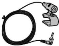
natural_image
Illustration of a black cable with a connector and a mechanical clamp (no text or symbols)GPS-AntenneMikrofon


flowchart
graph TD
    A["PORT1"] --> B["PORT2"]
    B --> C["PORT3"]
natural_image
Line drawing of a cable with connectors and a connector pin (no text or symbols)natural_image
Top-down view of a computer monitor layout with various electronic components and a highlighted circular component (no text or symbols)natural_image
Simple line drawing of a rectangular box with four small circular indentations on its faces (no text or symbols)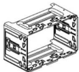
natural_image
Technical line drawing of a mechanical component housing (no text or symbols)natural_image
Simple line drawing of a rectangular frame with a horizontal bar at the bottom (no text or symbols)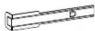
①Abdeckring
①Armaturenbrett
4BringenSiedenAbdeckringan.
①Abdeckring
②Nut
natural_image
Simple diagram of five circles arranged in two groups within a rectangular frame (no text or symbols)①Armaturenbrett ②Hutablage
natural_image
Illustration of a cable with a connector and a separate rectangular component (no text or symbols)①Mikrofonkabel
②Nut
①Mikrofon-Clip
②Kabelklemmen
①Mikrofon
②Zunge
③Mikrofonsockel
④Mikrofon-Clip

natural_image
Diagram of a car interior showing steering wheel and dashboard, with a close-up inset of the dashboard component (no text or symbols)natural_image
Diagram of a handheld electric shaver with rotating arrows indicating rotation (no text or symbols)
natural_image
Front view of a flat-screen computer monitor with control buttons and a scroll wheel (no visible text or symbols on the screen)F980DABF 980BT F9880DAB F9880BT

natural_image
Diagram of a blank digital tablet device with control panel and scroll arrows (no text or symbols)natural_image
Illustration of a hand holding a battery with a pin, showing its electrical connection to the right (no text or symbols present)
Voorkomenvan beschadigingen

WAARSCHUWING
ACC-standGeenACC-stand
natural_image
Technical line drawing of an electronic device and its wiring harness (no text or symbols)DitproductStroomsnoer
natural_image
Two types of electronic devices: a cable with connectors and a handheld device connected via a cable (no text or symbols visible)GPS-antenneMicrofoon

natural_image
Two technical line drawings: a wire with connector and a grid of labeled ports (no text or symbols present)USB-kabel (2st.)
IdentificatielabelsUSB-kabel
natural_image
Two technical illustrations of mechanical components: a cylindrical rod and a curved cable with connectors (no text or symbols)Draadbinder*1Voertuigbusconversiekabel*2
natural_image
Two simple 3D geometric shapes: a gray square and a wireframe rectangle (no text or symbols)①Haak
②Draadbinder
③HighSpeedHDMI ^® -kabel
L : Audio links (wit)
R: Audio rechts (rood)
V: Video (geel)
G: Aarde

Inbouwen
natural_image
Top-down view of a computer mouse with various electronic components and a highlighted circular component (no text or symbols)Bedekditgebiedniet.
natural_image
Simple line drawing of a rectangular frame with rounded corners and a central hole (no text or symbols)①Afwerkingsrand
①Uittreksleutel
① Dashboard
natural_image
Simple diagram of five circles arranged in two groups within a rectangular frame (no text or symbols)①Dashboard
②Hoedenplank
natural_image
Illustration of a handheld industrial tool with a coiled cable and connector (no text or symbols)②
①Microfoonkabel
②Groef
①Microfoonklem
②Klemmen

natural_image
Interior view of a car showing steering wheel and dashboard with a close-up inset of the dashboard (no text or symbols)natural_image
Diagram of a handheld electric plug with rotating arrows indicating motion (no text or symbols)
Nadeinstallatievandit product
natural_image
Diagram of a digital tablet device with control panel and display screen (no text or symbols)©2016PIONEERCORPORATION.
Allrightsreserved.
©2016PIONEERCORPORATION.
Tousdroitsdereproductionetde
traductionréservés.