Oscar Twin 14 AMR214CTA - Air Conditioning ARGO - Free user manual and instructions
Find the device manual for free Oscar Twin 14 AMR214CTA ARGO in PDF.
| Brand | ARGO |
| Model | Oscar Twin 14 AMR214CTA |
| Product type | Mobile split air conditioner (indoor + outdoor unit) |
| Power supply | 220-240 V ~ 50 Hz |
| Recommended electrical protection | Bipolar switch, 10 A time-delay fuse, 35 A circuit breaker (peak) |
| Indoor operating temperature | Min 15 °C DB / 12 °C WB - Max 32 °C DB / 23 °C WB |
| Outdoor operating temperature | Min 15 °C DB - Max 46 °C DB |
| Operating modes | Cooling, ventilation only |
| Fan speeds | High and low |
| Thermostat | Electronic, adjustable |
| Air filter | Standard filter + air purification filter (deodorizing) |
| Filter maintenance | Check every two weeks, clean with lukewarm soapy water or vacuum |
| Purification filter replacement | When its color becomes as dark as the reference label |
| Timer | Electronic 24h, daily and weekly programming, up to 8 ON and 8 OFF programs |
| Timer functions | Automatic On/Off, Auto mode, Skip mode, Random function |
| Condensate drainage | Automatic (red alarm indicator if malfunction) |
| Outdoor installation | On windowsill (type A), with basket (type B) or sliding bracket (type C) |
| Mobility | Wheels for moving, carrying handles |
| Supplied accessories | Flexible hose, basket kit or bracket (depending on version) |
| Safety | Automatic compressor stop (3 min after stop), overload protection |
| Storage | Drain condensate, store vertically, hang outdoor unit |
Frequently Asked Questions - Oscar Twin 14 AMR214CTA ARGO
User questions about Oscar Twin 14 AMR214CTA ARGO
0 question about this device. Answer the ones you know or ask your own.
Ask a new question about this device
Download the instructions for your Air Conditioning in PDF format for free! Find your manual Oscar Twin 14 AMR214CTA - ARGO and take your electronic device back in hand. On this page are published all the documents necessary for the use of your device. Oscar Twin 14 AMR214CTA by ARGO.
USER MANUAL Oscar Twin 14 AMR214CTA ARGO
natural_image
Line drawing of a portable air conditioner connected to a smaller front-mounted device (no text or symbols)MOVABLE AIR CONDITIONER with remote condenser CLIMATIZZATORE PORTATILEcon condensatore remoto CLIMATISEUR MOBILE avec condenseur a air extérieur MOBILES KLIMAGERÄT mit Außenkondensator AR CONDICIONADO com condensador remoto
CONTENTS
PRODUCT IDENTIFICATION....2
CONTROL PANEL 2
BEFORE USING THE APPLIANCE ....3
AIR CONDITIONER INSTALLATION ....4
OPERATION
Cooling 5
Fan only 5
SETTING AIR FLOW DIRECTION 5
ACCESSORIES (SUPPLIED ON REQUEST) 6
Air clean filter 6
Supplementary basket or support guide kit for outdoor unit.... 6
CARE AND CLEANING 7
USEFUL ADVICE 7
DECLARATION OF CONFORMITY
This product is marked as it satisfies Directives:
– Low voltage no. 73/23 EEC and 93/68 EEC.
- Electromagnetic compatibility no. 89/336 ECC, 92/31 EEC and 93/68 EEC.
This declaration will become void in case of of misuse and/or non observance though partial of manufacturer's installation and/or operating instructions.
PRODUCT IDENTIFICATION
text_image
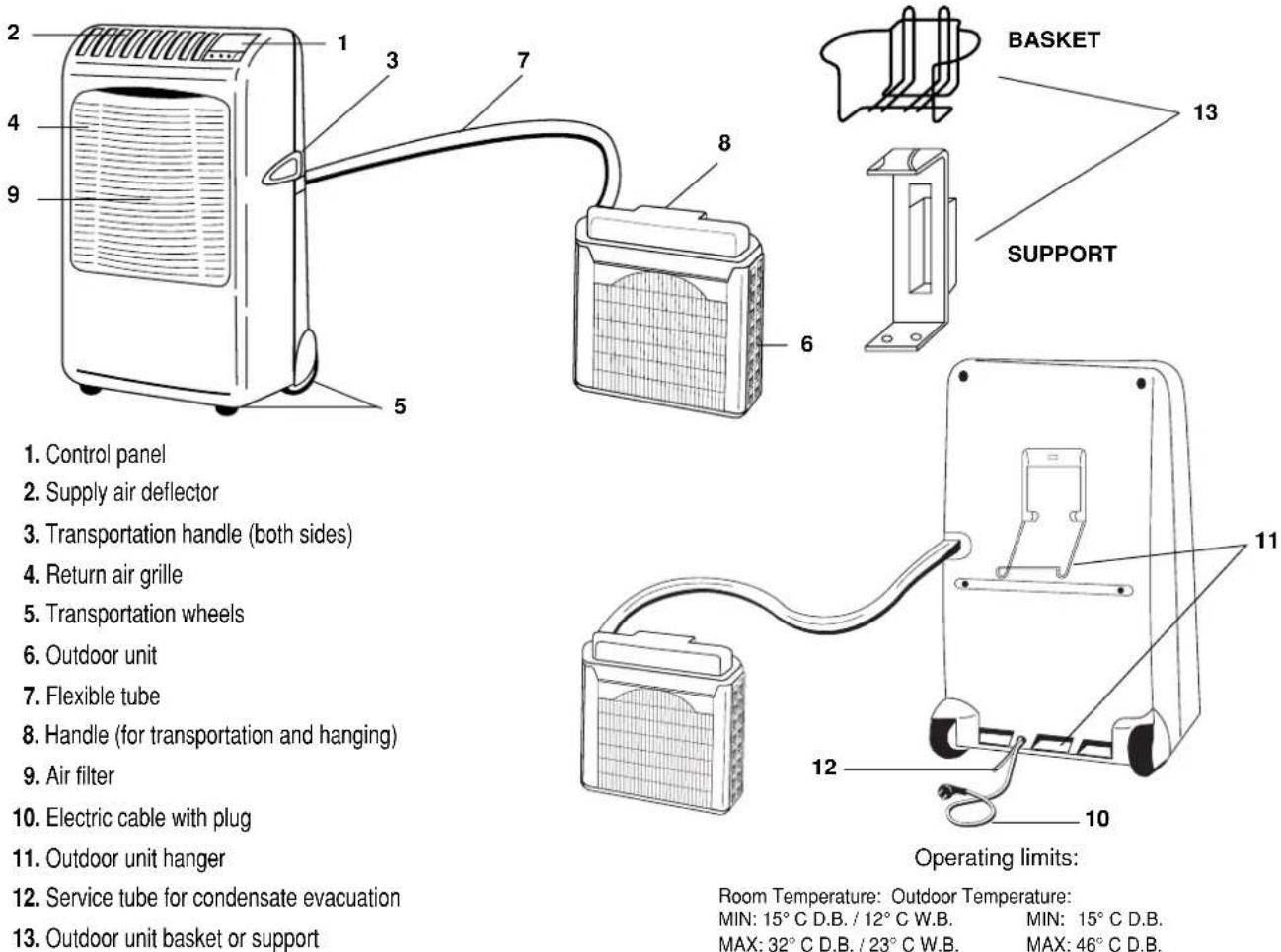
1. Control panel 2. Supply air deflector 3. Transportation handle (both sides) 4. Return air grille 5. Transportation wheels 6. Outdoor unit 7. Flexible tube 8. Handle (for transportation and hanging) 9. Air filter 10. Electric cable with plug 11. Outdoor unit hanger 12. Service tube for condensate evacuation 13. Outdoor unit basket or support 7 8 6 13 BASKET SUPPORT 11 12 10 Operating limits: Room Temperature: Outdoor Temperature: MIN: 15° C D.B. / 12° C W.B. MAX: 32° C D.B. / 23° C W.B. MIN: 15° C D.B. MAX: 46° C D.B.CONTROL PANEL
-
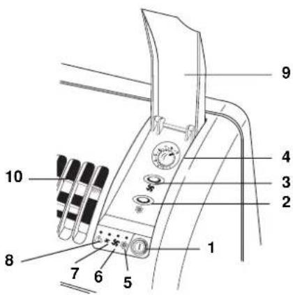
ON/OFF Push-button switch ①
-
Cooling push-button
-
High / Low fan speed push-button
-
Electronic thermostat Knob
-
Cooling lamp
-
High fan speed lamp
-
Low fan speed lamp
-
WATER LEVEL ALARM (RED)
It lights-on in case of misfunctioning of condensate evacuation system.
-
Control panel cover
-
Supply air deflector in vertical position
text_image
Labeled diagram of a mechanical device with numbered parts for identificationBEFORE USING THE APPLIANCE
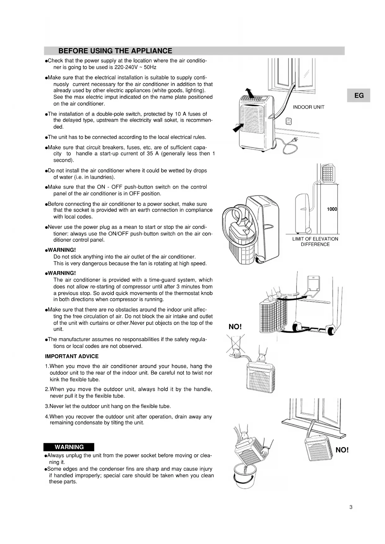
- Check that the power supply at the location where the air conditioner is going to be used is 220-240V \~ 50Hz
●Make sure that the electrical installation is suitable to supply continuously current necessary for the air conditioner in addition to that already used by other electric appliances (white goods, lighting). See the max electric input indicated on the name plate positioned on the air conditioner.
●The installation of a double-pole switch, protected by 10 A fuses of the delayed type, upstream the electricity wall soket, is recommended.
●The unit has to be connected according to the local electrical rules.
●Make sure that circuit breakers, fuses, etc, are of sufficient capacity to handle a start-up current of 35 A (generally less then 1 second). - Do not install the air conditioner where it could be wetted by drops of water (i.e. in laundries).
●Make sure that the ON - OFF push-button switch on the control panel of the air conditioner is in OFF position.
●Before connecting the air conditioner to a power socket, make sure that the socket is provided with an earth connection in compliance with local codes.
●Never use the power plug as a mean to start or stop the air conditioner: always use the ON/OFF push-button switch on the air conditioner control panel.
●WARNING!
Do not stick anything into the air outlet of the air conditioner. This is very dangerous because the fan is rotating at high speed.
●WARNING!
The air conditioner is provided with a time-guard system, which does not allow re-starting of compressor until after 3 minutes from a previous stop. So avoid quick movements of the thermostat knob in both directions when compressor is running.
●Make sure that there are no obstacles around the indoor unit affecting the free circulation of air. Do not block the air intake and outlet of the unit with curtains or other. Never put objects on the top of the unit.
●The manufacturer assumes no responsibilities if the safety regulations or local codes are not observed.
IMPORTANT ADVICE
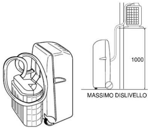
- When you move the air conditioner around your house, hang the outdoor unit to the rear of the indoor unit. Be careful not to twist nor kink the flexible tube.
- When you move the outdoor unit, always hold it by the handle, never pull it by the flexible tube.
- Never let the outdoor unit hang on the flexible tube.
- When you recover the outdoor unit after operation, drain away any remaining condensate by tilting the unit.
WARNING
●Always unplug the unit from the power socket before moving or cleaning it.
- Some edges and the condenser fins are sharp and may cause injury if handled improperly; special care should be taken when you clean these parts.
text_image
INDOOR UNIT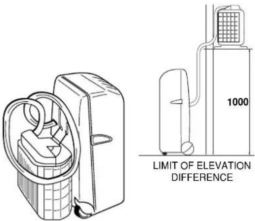
text_image
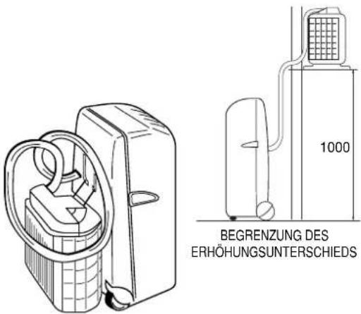
1000 LIMIT OF ELEVATION DIFFERENCE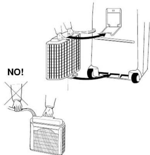
text_image
NO!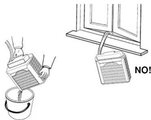
natural_image
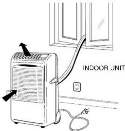
Illustration showing a bucket pouring liquid from a container into a bucket and a window frame with a handle (no text or symbols)The air conditioner is made of two units interconnected by a flexible tube. The indoor unit, movable on wheels, must be placed in the room to be air conditioned, near a window, a balcony-door or a perimeter wall. The outdoor unit, that provides to the disposal of heat and condensation, must be located outside, on a window sill, on a balcony or hanged to the wall.
POSITIONING OF OUTDOOR UNIT
The outdoor unit must always be kept in vertical position and levelled. Make sure that there are no obstacles around the unit affecting the free circulation of air. A lug at the rear bottom of the unit ensures the minimum distance from the wall (3 cm). The unit must be kept at a minimum distance of cm. 15 (sidewise) and cm. 80 (frontally) from any walls.
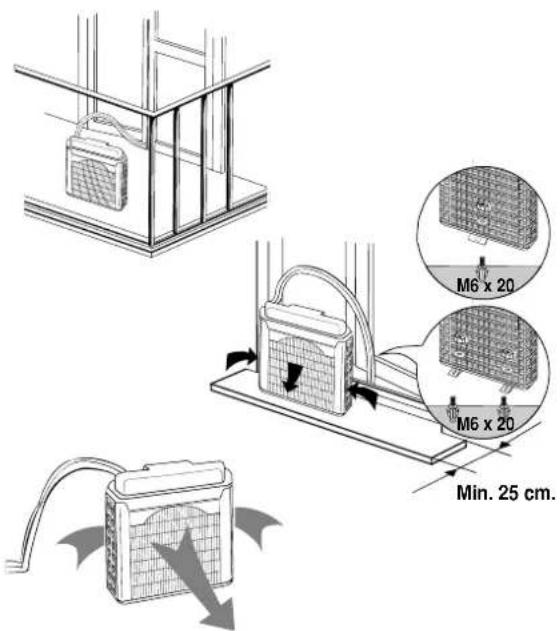
INSTALLATION TYPE A
If your room has a balcony or a window-sill of sufficient depth (min. 25 cm) you may rest the unit freely onto it. For safety's sake, you may anchor the unit to the window-sill using one M6 x 20 expansion bolt in the slot of the lug at the rear bottom of the unit.
The flexible tube may easily pass through the balcony door or window shutters set ajar.
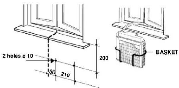
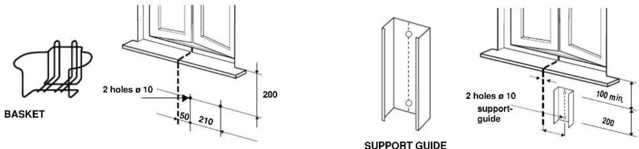
INSTALLATION TYPE B (USING THE BASKET)
- Fix the basket to the wall below the window sill.
- Place the unit in the basket and check that it is levelled.
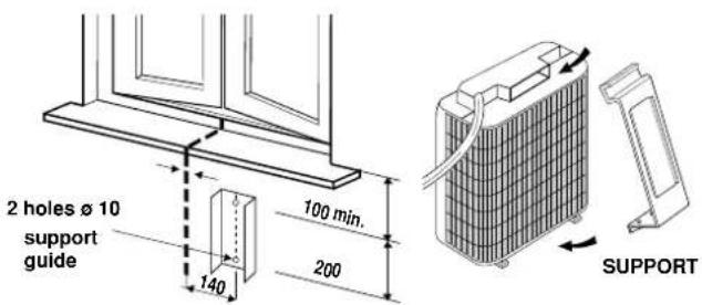
INSTALLATION TYPE C (USING THE SUPPORT)
- Fix the support guide to the wall below the window sill.
- Insert the support in the handle of outdoor unit, and turn the outdoor unit upside down as shown in the picture.
- Place the support and secure it at the edge of the unit, using the screws.
- Insert the support, fixed on the unit, at the guide fixed to the wall. Make sure it is levelled.
text_image
M6 x 20 M6 x 20 Min. 25 cm.TYPE A
text_image
2 holes ø 10 50 210 200 BASKETTYPE B
text_image
2 holes Ø 10 support guide 140 100 min. 200 SUPPORT
natural_image
Technical illustration of a solar panel installation and its internal components (no text or symbols)TYPE C
OPERATION
COOLING
Place the outdoor unit outside and insert the plug in the power socket.
- Twist the knob (4) of the thermostat to the right until you reach the position of maximum cooling.
- Switch on the air conditioner pressing the ON/OFF push-button (1) ① , lamps of last operations are displayed.
- Select the cooling operation (2), lamp (5) lights. ✦ pressing the push-button
- Press the push-button (3) to select the high fan speed, the lamp (6) lights.
- When room temperature has reached the most suitable value for your comfort, press again the push-button (3) to select the low fan speed, the lamp (7) lights.
- Now slowly twist the thermostat knob back towards the left until the compressor stops. At this point the air conditioner is set for automatic operation under the control of the electronic thermostat to maintain the room temperature at the preset value.
- To stop the air conditioner press again the ON/OFF push-button. (1).
FAN ONLY
For this operation the outdoor unit can be placed either outside (on the window sill or hanged to the wall) or inside, hanged to the indoor unit.
The air conditioner is running in cooling mode.
- Press the cooling push-button (2) to stop the compressor, lamp (5) is relised (disactivated).
- Select the fan speed pressing the fan speed push-button (3).
Starting the air conditioner in fan only mode.
- Switch on the air conditioner pressing the ON/OFF push-button (1).
●Make sure that the lamp (5) is relised (disactivated). - Select the fan speed pressing the fan speed push-button (3).
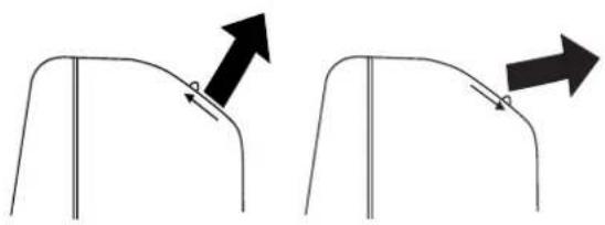
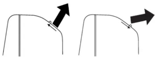
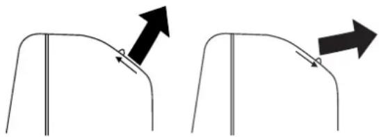
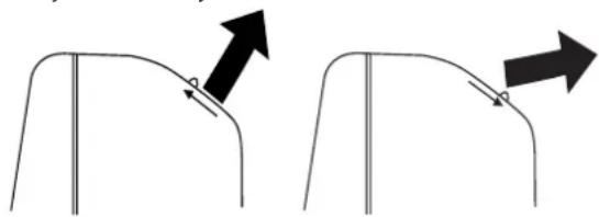
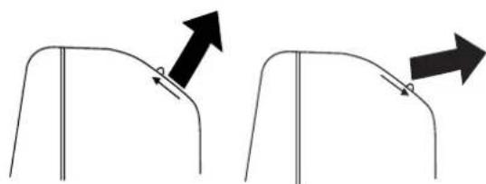
SETTING AIR FLOW DIRECTION
To set the air flow direction, seize with both hands one of the deflector blades and pull towards you.
Vertical Flow Horizontal Flow
natural_image
Two diagrams showing a curved object with arrows indicating direction, no text or symbols present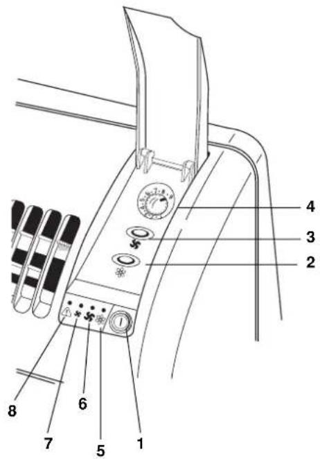
text_image
Technical diagram of a mechanical device with numbered parts labeled 1 through 8ACCESSORIES (SUPPLIED ON REQUEST)
AIR CLEAN FILTER
- Read these instructions before starting replacement work.
- This "Air Clean Filter" collects dust as well as deodorizes.
NOTE
- This carton box contains an air clean filter, a spring and a label "Color gauge for filter replacement".
- Open the bag just before installing the air clean filter. If not, the deodorization effect durability of the filter may be decreased.
text_image
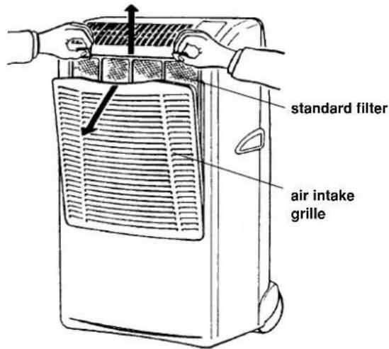
standard filter air intake grille1 Filter installation procedure:
Open the air intake grille and remove the standard filter. Stick the label "Color gauge for filter replacement" in an easy-to-see postion (inside of control panel cover).
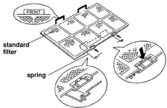
2 Attach the spring onto the standard filter:
Hook the spring onto the air filter from its rear side and engage it into the groove on the "FRONT" mark side (use of a standard screwdriver is recommended to easy setting).
3 Secure the "air clean filter" onto the standard filter by the spring attached before in step 2.
4 Set the standard filter in the air conditioner with its "FRONT" mark towards you and close the air intake grille.
Replacement of air clean filter
• The air clean filter is disposable.
- Do not throw away the filter frame and sping.
- The used filter cannot be reused even after cleaning up.
- Buy the air clean filter for replacement at your nearest dealer.
- Check the state of dirtiness at least once every two weeks and replace the filter when it changes to be so dirty as the color of the label "Color gauge for filter replacement".
text_image
FRONT standard filter spring
"Air clean filter" standard filter side: white (dust collecting filter) Spring side: black (deodorizing filter)

text_image
standard filterspring
SUPPLEMENTARY BASKET OR SUPPORT GUIDE KIT FOR OUTDOOR UNIT
If you want to utilise the air conditioner in several rooms, it is possible to buy varies baskets or support guides for the installation of outdoor unit.
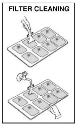
CARE AND CLEANING
WARNING! For safety's sake, be sure to turn the air conditioner OFF and also disconnect it from the power supply before cleaning it.
1. Cleaning of the Air Filter
The air filter must be checked at least once every two weeks operation. Operation with a dirty filter always causes a lower efficiency of the air conditioner and severe product damage. The filter is located at the back of the intake grille in the front of the air-conditioner and shall be removed from the upper side of the unit. Use a vacuum cleaner to remove light dust. If there is sticky dust on the filter, wash it with lukewarm soapy water, then rinse in clean, cold water and dry it before reinstallation.
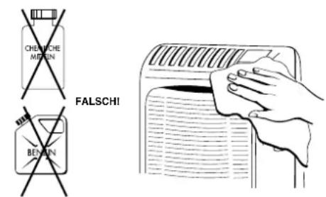
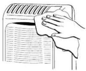
2. Cleaning of Casing and Grille.
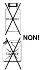
To clean the air conditioner, wipe it with a clean soft cloth, lightly moisted. In case it is stained, moisten the cloth with soapy water. Never use solvents or harsh chemicals, nor very hot water. Do not pour water over the air conditioner to clean it: this will damage the internal components and cause an electric shock hazard.
3. Storage.
If you are not going to make use of the air conditioner for a long period, before storing it away clean the air filter and evacuate the condensate from the indoor unit through the rear drain pipe and from the outdoor unit tilting it. Do not disconnect the flexible tube, unless you are obliged to do it: in that case protect the open halves of the couplings with the plugs supplied as accessories, that must be tightened with a spanner. Always store the unit in the vertical position hanging the outdoor unit by the handle to the rear of the indoor unit. Do not put heavy objects on top of the unit and protect it with a cloth or a plastic bag.
4. Transport.
Preferably keep the air conditioner in the vertical position during transportation. If this is not possible, then lay it on one side; when at destination put the air conditioner back in the vertical position and wait at least 10 minutes before using it for cooling.
- For your safety care check periodically the conditions of the electric supply cable; the electrical connection of the unit is X type with cable prepared in a special way; in case you should notice any damage due to usage, call the nearest After Sale Service to get the cable replaced.
text_image
FILTER CLEANING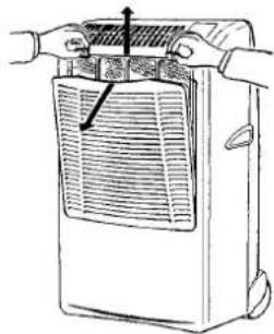
natural_image
Line drawing of a portable air conditioner unit with hands operating it (no text or symbols)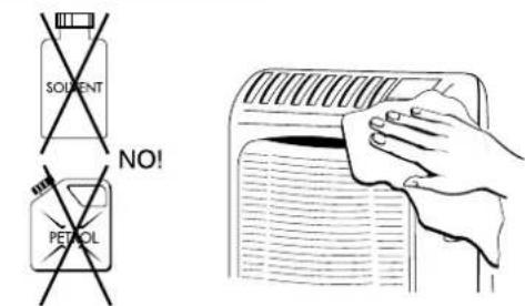
text_image
SOLVENT NO! PETROL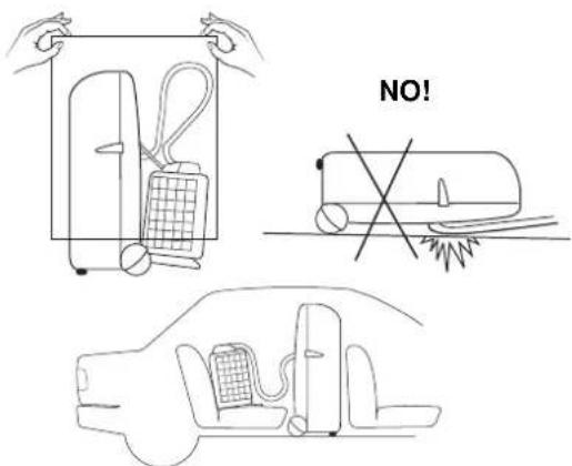
text_image
NO!USEFUL ADVICE
If your air conditioner doesn't work properly, first check the following points before requesting service:
●the plug is properly inserted into the power socket;
●the circuit breaker is in the ON position and fuses have not blown;
●the air filter is not clogged;
●the flexible tube is correctly positioned without any sharp bends nor plies;
- the thermostat knob is in the proper position for the suitable temperature (twisting it clockwise verify the compressor re-start, after the delayed time);
•the room temperature is above 15 °C;
- you have correctly carried-out the instructions contained in this manual;
The lighting-up of lamp ⚠️, together with the stop of the air conditioner indicate that the condensate pump is not working or that the condensate drain pipe in the flexible connection pipe is obstructed. In this case contact the After Sale Service.
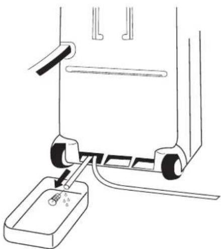
In case of emergency the air conditioner can work by draining the condensate from the back little pipe into a rather short container; extract the little pipe and remove the cap. (See picture)
natural_image
Diagram of a mechanical device with a base and adjustment lever, no text or symbols presentINDICE
IL PRODOTTO 2
PANNELLO COMANDO E CONTROLLO 2
PRIMA DI USARE IL CLIMATIZZATORE ....3
INSTALLAZIONE DEL CLIMATIZZATORE 4
MODALITÁ D'USO
Raffreddamento 5
MIN: 15° C B.S. / 12° C B.U.
MAX: 32° C B.S. / 23° C B.U.
MIN: 15°C B.S.
MAX: 46° C B.S.
PANNELLO COMANDO E CONTROLLO
text_image
Labeled diagram of a sewing machine with numbered parts for identificationPRIMA DI USARE IL CLIMATIZZATORE
text_image
UNITA' INTERNA|
text_image
MASSIMO DISLIVELLO 1000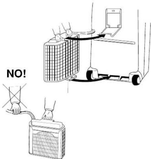
text_image
NO!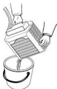
natural_image
Illustration of hands pouring liquid from a container into a bucket (no text or symbols)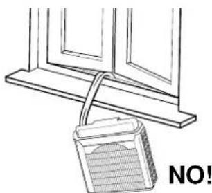
natural_image
Simple line drawing of a window frame with a bucket and label 'NO!' (no text or symbols on the diagram itself)text_image
Labeled diagram of a mechanical device with numbered parts and adjustment knobsnatural_image
Diagram showing two curved structural components with directional arrows indicating movement or force (no text or symbols)ACCESSORI (FORNITI SU RICHIESTA)
FILTRO ARIA PULITA
natural_image
Line drawing of a mechanical device with a base and adjustment lever (no text or symbols)SOMMAIRE
LE PRODUIT 2
TABLEAU DE COMMANDE 2
AVANT D'UTILISER LE CLIMATISEUR 3
INSTALLATION DU CLIMATISEUR 4
MODE D'EMPLOI
Refroidissement 5
Ventilation Seulement 5
REGLAGE DU FLUX D'AIR 5
ACCESSOIRES (FOURNIS SUR DEMANDE) 6
text_image
Labeled diagram of a sewing machine with numbered parts for identificationAVANT D'UTILISER LE CLIMATISEUR
natural_image
Diagram showing two views of a building structure: one with a grid-patterned panel and the other with a laptop and wall-mounted device (no text or symbols present)TYPE C
MODE D'EMPLOI
REFROIDISSEMENT
text_image
Labeled diagram of a mechanical device with numbered parts and adjustment knobsFlux vertical Flux Horizontal
natural_image
Diagram showing two views of a curved object with arrows indicating direction (no text or symbols)ACCESSOIRES (FOURNIS SUR DEMANDE)
FILTRE DE PURIFICATION DE L'AIR
natural_image
Line drawing of a refrigerator with hands operating it (no text or symbols)F
text_image
DISCUANT NON! ESSENCE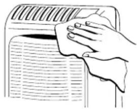
natural_image
Hand cleaning a car air conditioner cover with a cloth (no text or symbols visible)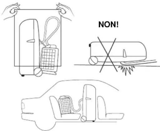
text_image
NON!CONSEILS UTILES
natural_image
Diagram of a mechanical device with a base and adjustment lever, no text or symbols presentINHALTVERZEICHNIS
DAS PRODUKT 2
SCHALT- UND KONTROLLPANEL 2
text_image
Labeled diagram of a sewing machine with numbered parts for identificationVOR INBETRIEBNAHME
text_image
INNENEINEITD
natural_image
Illustration of hands pouring liquid from a container into a bucket (no text or symbols)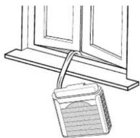
natural_image
Simple line drawing of a window frame with a hanging container (no text or symbols)FALSH!
text_image
Labeled diagram of a mechanical device with numbered parts and adjustment knobsVertikal Lufstrom Horizontal Lufstrom
natural_image
Two diagrams showing a curved object with arrows indicating direction, no text or symbols presentnatural_image
Line drawing of a portable air conditioner unit with hands operating it (no text or symbols)D
text_image
CHEMICALS METHNIC FALSCHI BENZIN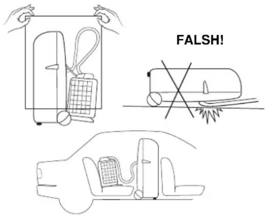
text_image
FALSH!natural_image
Line drawing of a mechanical device with a base and adjustment lever (no text or symbols)INDICE
EL PRODUCTO 2
PANEL DE MANDOS Y CONTROLES 2
ANTES DE USAR EL ACONDICIONADOR ....3
INSTALACION DEL ACONDICIONADOR ....4
COMO USARLO
Refrigeración ....5
Ventilación ....5
REGULACION DEL FLUJO DEL AIRE 5
ACCESORIOS (SUMINISTRADOS BAJO PEDIDO) 6
MIN: 15° C B.S. / 12° C B.H. MIN: 15° C B.S.
MAX: 32° C B.S. / 23° C B.H. MAX: 46° C B.S.
PANEL DE MANDOS Y CONTROLES
text_image
Labeled diagram of a mechanical device with numbered parts, likely a sewing machine or clamp mechanism.ANTES DE USAR EL ACONDICIONADOR
natural_image
Illustration showing a bucket pouring liquid from a container into a bucket and a wall-mounted device with a label 'NO!' (no text or symbols on the diagram itself)text_image
Labeled diagram of a mechanical device with numbered parts and adjustment knobsFlujo Vertical Flujo Horizontal
natural_image
Diagram showing two views of a curved object with arrows indicating direction (no text or symbols)ACCESSORIOS (SUMINISTRADOS BAJO PEDIDO)
FILTRE AIRE LIMPIA
natural_image
Line drawing of a portable air conditioner unit with hands operating it (no text or symbols)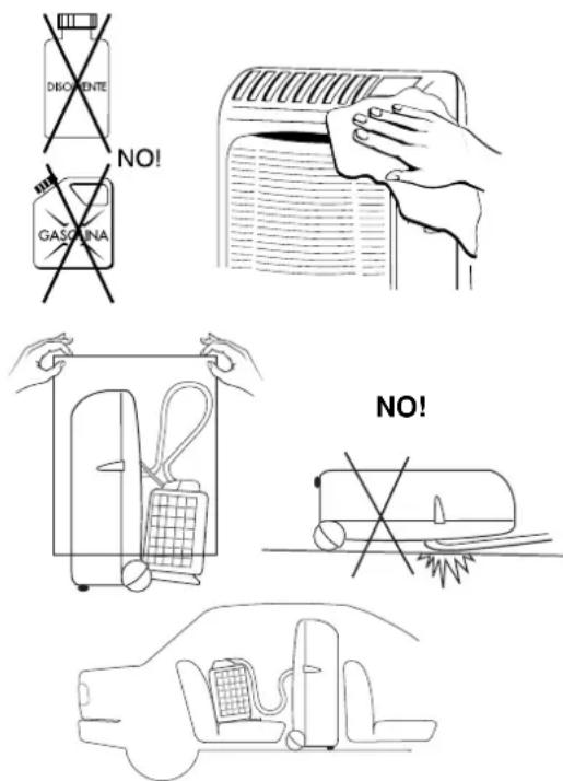
text_image
DISGIENTE NO! GASQUINA NO!CONSEJOS PRACTICOS
natural_image
Line drawing of a mechanical device with a base and adjustment lever (no text or symbols)CONTÉM
text_image
Technical diagram of a portable electronic device with labeled parts including battery, cable, and ports 10 and 11Limites de funcionamento:
Temperatura Interior (dentro de casa) MIN: 15° C B.S. / 12° C B.H.
MAX: 32° C B.S. / 23° C B.H.
Temperatura Exterior (for a de casa) MIN: 15° C B.S.
MAX: 46° C B.S.
PAINEL DE COMANDOS E CONTROLO
text_image
Labeled diagram of a device with numbered parts, likely for assembly or labeling purposes.ANTES DE USAR O APARELHO
natural_image
Technical illustration of a mechanical assembly with cross-sectional views and component details (no text or symbols)TIPO C
FUNCIONAMENTO
REFRIGERAÇÃO
Coloque a unidade exterior do lado de for a e ligue o cabo eléctrico na tomada.
text_image
Labeled diagram of a device control panel with numbered parts for identificationFluxo Vertical Fluxo Horizontal
natural_image
Two-step diagram showing a curved object with an arrow indicating direction, no text or symbols presenttext_image
FILTER CLEANING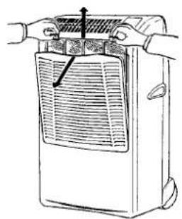
natural_image
Line drawing of a hand holding a portable air conditioner unit with a grille and ventilation slots (no text or symbols)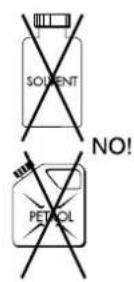
natural_image
Illustration of a hand cleaning a wall-mounted air conditioner (no text or symbols)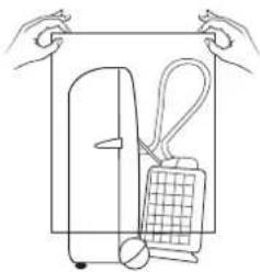
natural_image
Line drawing of hands holding a rectangular object with a grid and handle, no text or symbols present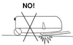
text_image
NO!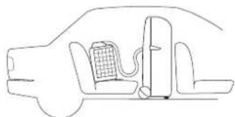
natural_image
Line drawing of a car interior with battery and valve (no text or symbols)CONCELHOS UTÉIS
natural_image
Diagram of a mechanical device with a base and adjustment lever, showing no text or symbolsElectric wiring diagrams' symbols / Simboli schemi elettici / Symboles des schemas électriques / Symbole der System-Schaltplanen Símbolos de los esquemas eléctricos / Símbolos dos esquemas eléctricos / MM ΩN Y M ΩN
| SYMBOL | EG | I | F | D | E | P | GR |
| PC | CONDENSATE PUMP MOTOR | MOTORE POMPA CONDENSIA | MOTEUR POWPE CONDENSATION | KONDEWSWASSERPUMPE-MOTOR | MOTOR BOMBA DE AGUA | MOTOR BOMBA DE AGUA | |
| CM | COMPRESSOR MOTOR | MOTORE COMPRESSORE | MOTEUR DE COMPRESSEUR | KOMPRESSORMOTOR | MOTOR DEL COMPRESOR | COMPRESSOR | |
| C1, 2, 3,4 | CAPACITOR | CONDENSATORE | CONDENSATEUR | KONDENSATOR | CONDENSADOR | CONDENSADOR | |
| DEF THERMO | DEFROST THERMOSTAT | TERMOSTATO-SBRINATORE | THERMOSTAT DE DEGVRAGE | ENTFROSTER-THERMOSTAT | TERMOSTATO DE DESCONGELACION | TERMOSTATO DE DESCOVGELAÇAO | |
| FLP | FLP MOTOR | MOTORE DEPLETTORE | MOTEUR DE VOLET | KLAPPENMOTOR | MOTOR DEL DEFLECTOR | MOTOR DA PLACA | |
| LM | LOUVER MOTOR | MOTORE DEPLETTORE | MOTEUR D'AUMENT | LUFTKLAPPENMOTOR | MOTOR CON ABERTURAS | MOTOR COM ABERTURAS LATERAIS | |
| FMO | OUTDOOR FAN MOTOR | MOTORE ESTERNO VENTOLA | MOTEUR DE VENTILATEUR EXTERIEUR | ALSSENÜFTERMOTOR | MOTOR EXTERIOR DE LA TURBINA | MOTOR DA VENTONHA EXTERIOR | |
| FM1, FM | INDOCR FAN MOTOR | MOTORE INTERNO VENTOLA | MOTEUR DE VENTILATEUR INTERIEUR | INNENLÜFTERMOTOR | MOTOR INTERIOR DE LA TURBINA | MOTOR DA VENTONHA INTERIOR | |
| IND. ASSY | INDICATOR ASSY | GRUPPO INDICATORI | ENSEMBLE INDICATEUR | EANZEIGE-BAUGRUFPE | GRUPO DE INDICADORES | GRUPO DE INDICADORES | |
| MG | MAGNETIC CONTACTOR | COMMITTORHEIMAGNETICO | CONTACTEUR MAGNETIQUE | MAGNETKONTGEBER | CONTACTOR MAGNÉTICO | CONTACTOR MAGNETICO | |
| NF | NOISE FILTER | FILTRO RUMORE | FILTRE ANTI PARASSITE | LÄRWSCHUTFILTER | FILTRO DEL RUDO | FILTRO DE RUDO | |
| OLR | OVERLOAD RELAY | RELÉ SOVRACCARICO | RELAIS DE SURCHARGE | ÜBERLASTRELAIS | RELÉ DE SOBRECARGA | RELÉ DE SOBRECARGA | |
| CE | CONTROLLER | SCHEDA ELETTRICA | CARTE ELECTRONIQUE | STEUERGERÄT | CONTROLADOR | PAINEL ELÉTRICO | |
| PR | POWER RELAY | RELÉ ALIMENTAZIONE | RELAIS D'ALIMENTATION | LEISTUNGSRELAIS | RELÉ DE ALIMENTACIÓN | RELÉ DA ALIMENTAÇÃO | X |
| RP | PUMP RELAY | RELÉ POMPA | RELAIS POMPE | PUMPE RELAIS | RELÉ BOMBA DE AGUA | RELÉ BOMBA | |
| SSR | SOLD STATE RELAY | RELÉ STATO SOLIDO | RELAIS A SEMI-CONDUCTEUR | FESTKÖRPERRELAS | RELÉ DEL ESTADO SOLIDO | RELÉ CO ESTADO SÓLIDO | |
| RA | STARTING RELAY | RELÉ CI AVVAMIENTO | RELAIS DE DEMARRAGE | STARTRELAS | RELÉ DE ARRANQUE | RELÉ DE ARRANQUE | |
| SV | SOLENOID VALVE | VALVOLA SOLENOIDE | ELECTROWANNE | MAGNETVENTIL | VALVULA SOLENOIDE | VALVULA SOLENOIDE | |
| MS | SAFETY FLOAT SWITCH | GINT. SICUREZZA MIGAILL | INTERRI LE SECURITE A FLOTTEUR | SCHWEIMA-SCHUTZSCHALTER | INTERRI. DE SEGURIDAD DE FLOTADOR | INTERRI. DE SEGURAMA | |
| ON-OFF SW | ON-OFF SWITCH | INTERPUTTORE MARCIA APRESTO | TOUCHE MARCHEARRÊT | ENCUS TOSTE | BOTON ARRANQUE PARADA | INTERRUPTOR-LUGAR DESLIGAR | |
| TH1, 2, | THERMISTOR | TERMISTORE | THERWISTANCE | THERMISTOR | TERMISTOR | TERMISTOR | |
| P | TIMER | PROGRAMMATORE | PROGRAMMATEUR | ZEITSCHALT-LHR | PROGRAMADOR | TIMER | |
| TR1, 2 | POWER TRANSFORMER | TRASFORMATORE DI POTENZA | TRANSFORMATEUR DE PUSSANCE | NETZTRANSFORMATOR | TRANSFORMADOR DE POTENCIA | TRANSFORMADOR DE CORRENTE | X |
| 20S | 4-WAY VALVE | VALVOLA 4 VIE | VAVME 4 VOIES | 4-WEG-VENTIL | VALVULA DE 4 VIAS | VALVULA DE 4 VIAS | 4 |
| 47C | NEGATIVE PHASE RELAY | RELÉ A FASE NEGATIVA | RELAIS D'ORDRE DE PHASE | NEGATIVPHASENRELAS | RELÉ DE FASE NEGATIVA | RELÉ DA FASE NEGATIVA | |
| LC | CURRENT LIMITER | LIMITATORE CORRENTE | LIMITEUR DE COURANT | STRON BERGRENZER | LIMITADOR DE CORRIENTE | LIMITADOR DE CORRIENTE |
Wires color legend
natural_image
Line drawing of a portable electronic device with buttons and wheels (no text or symbols)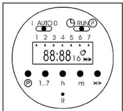
text_image
AUTO 0 RUN P 1 2 3 4 5 6 7 88:88 16 P 1..7 h m R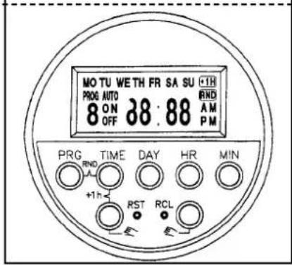
text_image
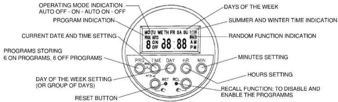
MO TU WE TH FR SA SU +1H PROG AUTO 8 ON 38:88 RND OFF A M PM PRG TIME DAY HR MIN +1h RST RCL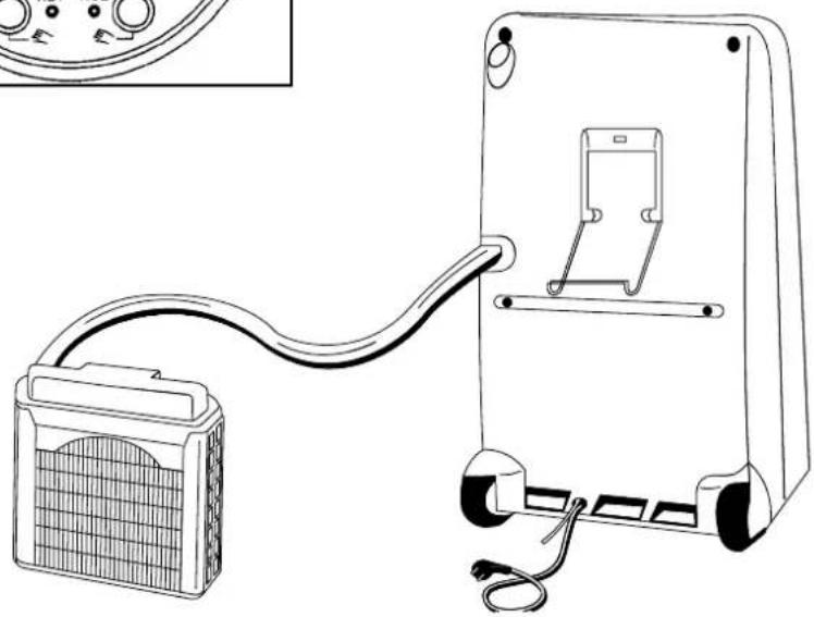
natural_image
Line drawing of a portable electronic device with cable and connector, no text or symbols presentMOVABLE AIR CONDITIONER • CLIMATIZZATORE PORTATILE CLIMATISEUR MOBILE • MOBILES KLIMAGERÄT ACONDICIONADOR PORTATIL
Technical data
- Programmed memory of up to 5 years without power supply due to Lithium battery
- Display 24 hours
– Daily and weekly programming possibility - 8 switching ON programs, 8 switching OFF programs
text_image
MANUAL OFF TIME SETTING OPERATING MODE PROGRAM MODE MANUAL ON AUTO 0 RUN P PROGRAM SETTING 1 2 3 4 5 6 7 88:88 16 SWITCH DAYS OF THE WEEK ON/OFF INDICATION PROGRAMS STORING 8 ON PROGRAMS, 8 OFF PROGRAMS P 1..7 h m R SKIP MODE INDICATION SKIP MODE ON/OFF MINUTES SETTING HOURS SETTING DAYS OF THE WEEK SETTING 1: MONDAY, 7: SUNDAY RESET BUTTONOperating modes of timer:
I: the air conditioner is permanently ON (use directly the ON/OFF push button of the air conditioner to switch it OFF)
AUTO: the timer will switch on and off the air conditioner according to the selected program
0: the air conditioner is permanently OFF (it can't be switched ON neither with the ON/OFF push button of the air conditioner)
OPERATING INSTRUCTIONS FOR THE TIMER
1. Reset of the timer:
Be sure that the switch is in the RUN position and press down the reset button R with the tip of a pencil (the display will begin blinking).
2. Setting the current time and day:
Slide the switch into position, press down the button 1...7 until you set the day of the current week (indicated by an arrow ▲ on the display), press down the button h to set the current hour, press down the button m to set the minutes. Slide again the switch into RUN position.
3. Selection of the days or the blocks of days to be set:
It is possible to set each single day and the following blocks of days, pressing the button 1...7:
1-2-3-4-5 (from Monday to Friday)
6-7(Saturday and Sunday)
1-2-3-4-5-6 (from Monday to Saturday)
1-2-3-4-5-6-7 (from Monday to Sunday)
4. Programming the switching times:
- Slide the switch into P position (the time indication on the display begins blinking, the bulb symbol and the number 1 of the first switching time are visualised).
- Press down the button 1...7 until you set the day of the week or the block of days to be stored (an arrow ▲ corresponding to the selected day or many arrows if you set a block of days will appear on the display).
- Press down the button h and then the button m to set the switching ON hour.
- Press the button P to set the switching OFF hour (the time indication on the display begins blinking again, the symbol of the bulb disappears and the number 2 appears).
- Confirm the day with the button 1...7 and set the switching OFF hour with the buttons h and m.
- Repeat these operations sequentially up to 8 switching ON and 8 switching OFF programs maximum, divided among the days you want to set.
- At the end of programming slide the switches into RUN and AUTO position.
NOTE: During the non set days the air conditioner will be OFF.
5. SKIP mode:
The SKIP mode (program override) can be set only during the automatic mode of the timer (AUTO) + (RUN); by pressing the skip button x, the timer will be switched into the opposite functional mode (from ON to OFF and vice versa); this mode remains activated up to the following set program.
When the skip mode is activated the skip symbol ✦appears on the display.
Pressing the SKIP button again will cancel the skip mode.
6. Visualisation, correction or deletion of the stored programs:
You can visualise the stored programs, during operation, sliding the switch into P position and pressing many times the P button.
In this way, you can modify the switching ON and OFF hours with the buttons h and m and delete one or more programs, pressing contemporary the buttons P and ✗.
ELECTRONIC BUILT-IN-TIMER 24 HOURS
Technical data
- Programmed memory without power supply: 150 hours
- Display 24 hours
– Daily and weekly programming possibility - 6 switching ON programs, 6 switching OFF programs
text_image
OPERATING MODE INDICATION AUTO OFF - ON - AUTO ON - OFF PROGRAM INDICATION MOTU WE TH FR SA SU +TH PROG AUTO 8 ON 38.88 RND AM PM CURRENT DATE AND TIME SETTING PROGRAMS STORING 6 ON PROGRAMS, 6 OFF PROGRAMS PRG TIME DAY HR MIN +1h RST RCL DAY OF THE WEEK SETTING (OR GROUP OF DAYS) RESET BUTTON DAYS OF THE WEEK SUMMER AND WINTER TIME INDICATION RANDOM FUNCTION INDICATION MINUTES SETTING HOURS SETTING RECALL FUNCTION: TO DISABLE AND ENABLE THE PROGRAMMSEG
OPERATING INSTRUCTIONS FOR THE TIMER
1. Reset of the timer:
Press down the RST (reset) button with the tip of a pencil.
2. Setting the current day and time:
Keep pressed down the TIME button while you are setting the current time or correcting it; press down the DAY button to set the current day (shown by the english abbreviation on the display), press down the HR button to set the current hour, press down the MIN button to set the current minutes.
3. Selection of the days or the groups of days to be set:
Press down PRG (programming) button once: you will see "PROG 1 ON" on the display which indicates the switch-on time command to be entered. Press the DAY button and the display will show you in sequence (each time you press it) the following groups of days or single days:
MO-TU-WE-TH-FR-SA-SU (group of days from Monday to Sunday)
MO-TU-WE-TH-FR-SA-SU (each day of the week, one by one)
MO-TU-WE-TH-FR (group of days from Monday to Friday)
SA-SU (Saturday and Sunday)
MO-TU-WE-TH-FR-SA (group of days from Monday to Saturday)
MO-WE-FR (Monday, Wednesday and Friday)
TU-TH-SA (Tuesday, Thursday and Saturday)
4. Programming the switching times:
After having pressed down the PRG button and then the DAY button until you set the day or the group of days to be stored (see section 3)
- Press down the HR button and then the MIN button to set the switching ON hour.
- Press the PRG button again to set the switching OFF hour (you will see "PROG 1 OFF" on the display which indicates the switch-off time command to be entered).
• Confirm the day or group of days with the DAY button and set the switching OFF hour with the HR and MIN buttons. - Repeat these operations in sequence up to 6 switching ON and 6 switching OFF programs maximum, divided among the days you want to set.
- At the end of programming press the TIME button to switch to the current time, otherwise these switching times will not be executed. (However, the display will be switched to current time mode automatically if no button is pressed within about 2 minutes).
NOTE: During the non set days the air conditioner will be OFF.
5. Visualise, correct, disable and enable the stored programs:
You can visualise the stored programs, during operation, pressing many times the PRG button.
In this way, you can modify the switching ON and OFF hours with the HR and MIN buttons and disable or enable one or more programs, pressing the RCL button (see RECALL function, section 6).
6. RECALL function:
The RECALL function allows you to disable a switching time of a program, without losing preset memory:
- Press the PRG button until the preset memory you want to disable is present
- Press RCL button, using the tip of a pencil (the set time disappears and the display shows “--:--” for the hours and minute, indicating that the specified memory location will not be executed).
• Press the TIME button to switch to the current time
• You can enable again the switching time, following the same procedure and pressing again the RCL button.
7. SUMMER/WINTER TIME change-over:
- To change from winter time to summer time, keep TIME button pressed while pressing one of the button (the display will indicate the “+1h” sign and the current time will be advanced one hour).
- To change from summer time to winter time simply perform the step before (the “+1hr” sign will disappear from the display and the current time will retard one hour).
8. RANDOM function:
The programmed memories you have preset will be executed in a random delay from 2 to 32 minutes, in case of current interruption, using this function.
- Keep the TIME button pressed while pressing PRG button (the display will indicate RND sign).
- Press again the TIME and PRG button to cancel the random mode (the RND sign will disappear from the display).
9. Manual operation:
If you press one of the 📋 buttons, you can set the timer manually; the display will show in the sequence: AUTO OFF-ON-AUTO ON-OFF
AUTO: the air conditioner is controlled by the timer (it is possible to change from AUTO ON to AUTO OFF or vice versa, if you want to switch on or off the air conditioner without losing the control of the timer that will go on executing the other set programs).
ON: the air conditioner is permanently ON (use directly the ON/OFF push button of the air conditioner to switch it OFF)
OFF: the air conditioner is permanently OFF (it can't be switched ON neither with the ON/OFF push button of the air conditioner)
- 6 programmes ON, 6 programmes OFF
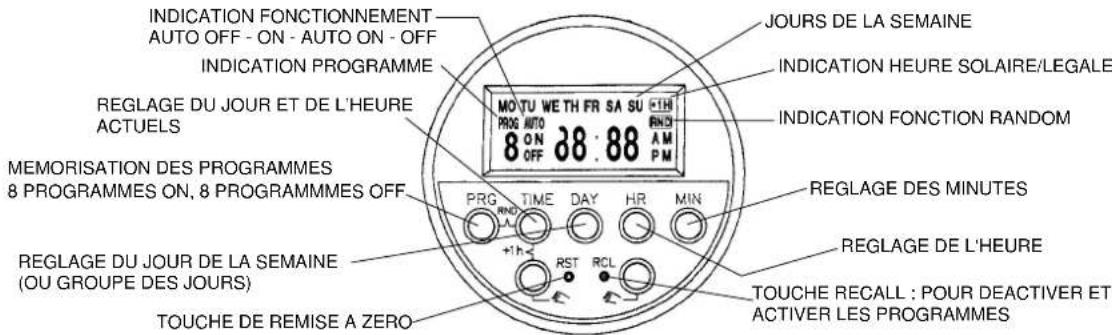
text_image
INDICATION FONCTIONNEMENT AUTO OFF - ON - AUTO ON - OFF INDICATION PROGRAMME MO T U W E T H F R S A S U +1H PROG AUTO 8 ON 38:88 RND OFF P M REGLAGE DU JOUR ET DE L'HEURE ACTUELS MEMORISATION DES PROGRAMMES 8 PROGRAMMES ON, 8 PROGRAMMES OFF PRG TIME DAY HR MIN +1h RST RCL TOUCHE DE REMISE A ZERO JOURS DE LA SEMAINE INDICATION HEURE SOLAIRE/LEGALE INDICATION FONCTION RANDOM REGLAGE DES MINUTES REGLAGE DE L'HEURE TOUCHE RECALL : POUR DEACTIVER ET ACTIVER LES PROGRAMMESF