
WALL 18000 UI - Air Conditioning ARGO - Free user manual and instructions
Find the device manual for free WALL 18000 UI ARGO in PDF.


| Product Type | Single-Split Air Conditioner |
| Model | WALL 18000 UI |
| Cooling Capacity | 18000 BTU/h |
| Operating Modes | Auto, Cool, Dry, Fan, Heat |
| Refrigerant | R410A (GWP = 2087.50) |
| Power Supply | 220-240 V ~ 50 Hz |
| Recommended Circuit Breaker | 10 A |
| Remote Control | Included (with LCD display) |
| Timer Function | 0.5 to 24 hours (ON/OFF) |
| Sleep Function | Available in Cool, Heat, Dry modes |
| Swing Function | Vertical oscillation of flaps |
| Fan Speeds | Auto, Low, Medium, High |
| Temperature Setting Range | 16 °C to 30 °C |
| Operating Temperature (Cooling) | Outdoor: -15 °C to +43 °C |
| Operating Temperature (Heating) | Outdoor: -7 °C to +24 °C |
| Maximum Pipe Length | 20 m |
| Maximum Height Difference | 10 m |
| Additional Refrigerant Charge | 20 g/m for liquid pipe Φ6.35 mm |
| Filter Cleaning Interval | Every 3 months |
| Error Codes | E5, E8, U8, H6, C5, F1, F2 |
| Safety Features | Auto shutdown, overload protection, earthing |
Frequently Asked Questions - WALL 18000 UI ARGO
User questions about WALL 18000 UI ARGO
0 question about this device. Answer the ones you know or ask your own.
Ask a new question about this device
Download the instructions for your Air Conditioning in PDF format for free! Find your manual WALL 18000 UI - ARGO and take your electronic device back in hand. On this page are published all the documents necessary for the use of your device. WALL 18000 UI by ARGO.
USER MANUAL WALL 18000 UI ARGO
USER AND INSTALLATION MANUAL
Single-Split Air Conditioner
WALL 9000
WALL 12000
WALL 18000

Please read this manual carefully before installing and using the air conditioner, and retain for future reference.
Contents
Information for use
Precautions for use 3
Description of components 4
Guide to the remote control and display
Remote control buttons 5
Getting to know the display icons 5
Getting to know the remote control buttons 5
Getting to know the button combination functions 7
Operating guide 8
Replacing the remote control batteries 8
Emergency operation 9
Maintenance
Care and cleaning 9
Troubleshooting
Possible faults and solutions 10
Analyzing faults and solutions 12
Installation instructions
Installation diagrams 13
Choosing a location for installation 14
Electrical connection requirements 15
Installation
Indoor unit installation 15
Outdoor unit installation 19
Vacuum pump 21
Post-installation checks 22
Testing and operation
Functional testing 22
Appendices
Piping configuration 23
Procedure for extending the piping 24

INFORMATION FOR CORRECT DISPOSAL OF THE PRODUCT IN ACCORDANCE WITH THE EUROPEAN DIRECTIVE 2012/19/EU
At the end of its working life this equipment must not be disposed of as an household waste. It must be taken to special local community waste collection centres or to a dealer providing this service. Disposing of electrical and electronic equipment separately avoids possible negative effects on the environment and human health deriving from an inappropriate disposal and enables its components to be recovered and recycled to obtain significant savings in energy and resources. In order to underline the duty to dispose of this equipment separately, the product is marked with a crossed-out dustbin.
INFORMATION FOR USE Precautions for use

WARNING
- This product is not a toy. Children should be properly supervised to ensure that they do not play with the appliance.
- This appliance should not be used by children under 8 years old or by persons with reduced physical, sensory or mental capabilities or lacking the necessary experience and knowledge, unless under supervision or given the necessary training concerning the use of the appliance by someone responsible for their safety.
- The unit must not be cleaned or serviced by children without supervision.
- To prevent the risk of fire, do not connect the air conditioner to a multifunction socket.
• Always disconnect the power before servicing or cleaning the unit. - To prevent the risk of electric shock or malfunction, do not spray water on the indoor unit.
- Do not spill water on the remote control.
- To prevent the risk of electrical shock or damage, do not attempt to repair the air conditioner yourself. After performing the checks in the troubleshooting section, contact an authorised service centre.
- Do not obstruct the inlet or outlet. Otherwise, a fault may occur.
- Contact a qualified technician if it is necessary to move the air conditioner to another location.
- Do not climb on or place heavy objects on the top panel of the outdoor unit. Otherwise, there is a risk of damage or personal injury.
- Do not put fingers or other objects in the air inlet/outlet grilles. Otherwise, there is a risk of damage or personal injury.
- The air conditioner must be properly earthed. Improper earthing can cause electrical shock.
- Always install a circuit breaker. Otherwise, a fault may occur.
- The unit must be installed and serviced by a qualified technician. Otherwise, there is a risk of damage or personal injury.
Operating limits
Operating range:
Cooling mode: from -15°C to +43°C (outdoor temperature)
Heating mode: from -7°C to +24°C (outdoor temperature)
Description of components
Indoor unit
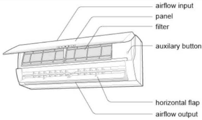

remote control

Outdoor unit

GUIDE TO THE REMOTE CONTROL AND DISPLAY Remote control buttons
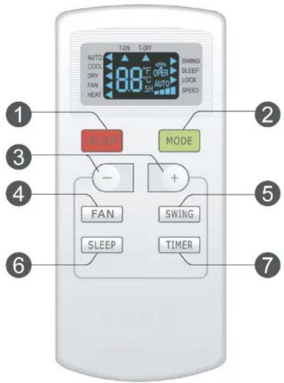
- ON/OFF button
- MODE button
- +/- button
- FAN button
- SWING button
- SLEEP button
- TIMER button
Getting to know the display icons

Getting to know the remote control buttons
N.B.:
- This is a general remote control, it could be used with air conditioners with different functions. For some modes, that the model does not have, if you press the corresponding button on the remote control the unit will keep its mode of operation
-
After connecting the power supply (standby) you can run the air conditioner by the remote control.
-
When you press the ON/OFF button on the remote control, the 📤 icon on the remote control display will flash once and the air conditioner will emit a beep. This means that the signal has been sent to the unit.
- When the unit is off, the temperature will be shown on the remote control, the correspondent icon will appear. If the unit is on, you will see the icon of the correspondent mode.
1. ON/OFF button
Press the ON/OFF button to turn the air conditioner on or off.
2. MODE button
Press this button to select the desired operating mode.
After selecting the mode, the correspondent light will turn on.
AUTO - COOL - DRY - FAN - HEAT
When you select automatic mode, the air conditioner will operate automatically according to the factory settings. The set temperature cannot be adjusted and will not be displayed. Pressing the "FAN" button will allow you to adjust the fan speed.
When you select cool mode, the air conditioner will run in cool mode. The cooling indicator will illuminate on the display. Press "+" or "-" to adjust the set temperature. Press the "FAN" button to adjust the fan speed.
When you select dry mode, the air conditioner will run at low speed in dry mode. The fan speed cannot be adjusted in this mode.
When you select fan mode, the air conditioner will operate only the fan, blowing air without cooling or heating. Press the "FAN" button to adjust the fan speed.
When you select heat mode, the air conditioner will run in heat mode. Press "+" or "-" to adjust the set temperature. Press the "FAN" button to adjust the fan speed.
3. +/- Button
Press "+" or "-" once to increase or decrease the set temperature by 1°C. Press and hold "+" or "-" for 2 seconds to rapidly adjust the set temperature on the remote control. When set-up is complete, release the button and the indoor unit's temperature indicator will change accordingly.
When setting the TIMER ON, TIMER OFF, press "+" or "-" to adjust the time. (Please refer to the relevant sections for TIMER ON and TIMER OFF buttons).
4. FAN button
Pressing this button will allow you to cycle through and set the fan speed: automatic AUTO, SPEED 1 ( ), SPEED 2 ( ), SPEED 3 ( ), SPEED 4 ( ):
AUTO -

Note that when you select AUTO, the unit will automatically select the most suitable fan speed according to the factory settings. The fan will operate at low speed in dry mode.
5. SWING button
Press this button to turn on or off the oscillation of the flaps.
6. SLEEP button
In the cooling, heating and dehumidification modes, press this button to activate the sleep function. Press this button to cancel the Sleep function. In the FAN and AUTO mode, this function is not available.
7. TIMER mode
When the unit is on, press this button to set the timer to turn off the unit. T-OFF and H will light. Within 5 seconds, press the + or - button to turn off the timer.
If you press the + or - button once, the timer will increase or decrease by 0.5 h. If you press the + or - button for 2 seconds, the time will change quickly. Release the button after the set time required is reached. Then press the TIMER button to confirm. The T-OFF and H icons will turn off.
When the unit is turned off, press this button to set the start time of the TIMER. T - ON and H light. Within 5 seconds, press the + or - to adjust the ignition. Pressing the + or - button once, the timer will increase or decrease by 0.5 h. Press the + or - button for 2 seconds, the time will change quickly. Release the button after the set time required is reached. Then press the TIMER button to confirm. The T-ON and H icons will turn off
Canceling set TIMER ON / OFF: If the timer is set, press the TIMER button once to see the remaining time that was set. Within 5 seconds, press the TIMER again to cancel this function.
Note: the interval of the setting time is from 0.5 to 24 hours.
The interval between the two settings can not exceed 5 seconds, otherwise the remote control will lose the settings.
Getting to know the button combination functions
Remote control button lock function
Press "+" and "-" simultaneously to enable or disable the remote control button LOCK function. When this function is enabled, will appear on the remote control display. If you attempt to operate the remote control, the LOCK icon will flash three times and no signal will be sent to the unit.
Switching temperature display
In OFF mode, press the "-" and "MODE" buttons simultaneously to switch from a temperature display in °C to °F.
Operating guide
- When you connect the power, press the "ON/OFF" button on the remote control to turn the air conditioner on.
- Press the MODE button to select the desired operating mode: AUTO, COOL, DRY, FAN or HEAT.
- Press "+" or "-" to adjust the desired temperature. (The temperature cannot be adjusted in automatic mode.)
- Press the "FAN" button to set the desired fan speed: automatic, low, medium or high.
- Press the "SWING" button to adjust the fan's angle of airflow.
Replacing the remote control batteries
-
Remove the battery compartment cover, marked with OPEN (see image to right), by sliding it in the direction of the arrow.
-
Use only two AAA - LR03 1.5V batteries. Make sure the + and - ends are facing the correct direction.
-
Slide the battery compartment cover back into place.
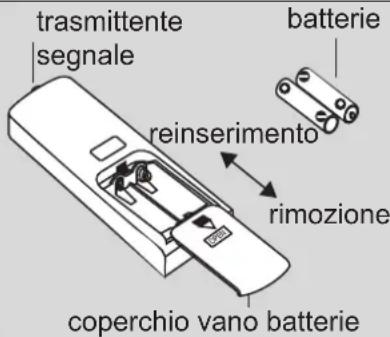
- When the unit is operating, point the remote control's signal transmitter at the indoor unit's receiver.
- The distance between the transmitter and the receiver must not exceed 8 metres and should remain free of obstacles.
- If the room contains a fluorescent light or cordless telephone, signal interference is likely to occur.
- When the remote control is not used for a month or more, remove the batteries.
- Use batteries of the same type when replacing the batteries, as necessary.
- If the icons on the remote control display are blurred or not visible, replace the batteries.
- Do not attempt to recharge the batteries. Replace both batteries at the same time.
- Do not throw batteries into fire; they may explode.

INFORMATION FOR THE CORRECT DISPOSAL OF BATTERIES IN ACCORDANCE WITH EUROPEAN DIRECTIVE
2006/66/EC
Replace batteries when they are depleted. At the end of their life, batteries must be disposed of separately from unsorted waste. They must be taken to designated recycling centres or returned to a retailer providing this service. Separate disposal of batteries helps to reduce the potential harmful effects on the environment and human health caused by their improper disposal and also enables the recovery and recycling of component materials, saving significant energy and resources. The requirement for separate disposal is indicated by the crossed-out wheelie bin label affixed to the appliance. Illegal disposal of the product by the user is subject to administrative penalties as per current regulations.
Emergency operation
In the event of loss or failure of the remote control, use the emergency button located under the indoor unit's front panel to turn the air conditioner on or off.
The unit will operate in automatic mode on start-up.
Use isolated objects to press the AUTO button.

| pannellino | panel |
| tastoausiliario | auxiliary |
button
MAINTENANCE
Care and cleaning
N.B.:
Disconnect the power before servicing or cleaning the unit.
Do not clean the unit with water to avoid electrical shocks.
Do not use volatile substances to clean the unit.
Cleaning the casing of the indoor unit
Use a soft, damp cloth to clean the outer surface of the unit.
Do not use water that is too hot, solvents, petrol or other aggressive chemical compounds, talcum powder or brushes. These may damage the colour or surface of the casing.
To remove stains, use warm water with a little neutral detergent.
Do not pour water onto the air conditioner to clean it. This may damage the internal components or cause a short circuit.
N.B.: Do not remove the panel when cleaning the unit.
Cleaning the filters
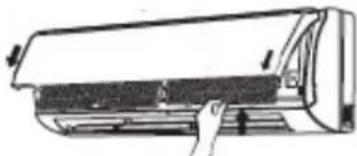
Open the panel
Lift the front panel of the indoor unit, as shown.

natural_image
Illustration of a hand lifting a wall-mounted air conditioner (no text or symbols)Remove the filters
Remove the filters by lifting one of the bottom corners and pulling them downwards, as shown.

natural_image
Illustration of a hand pressing down on a curved panel or panel (no text or symbols visible)Clean the filters
- Use a vacuum cleaner to clean the filters.
- If they are very dirty, use water (below 45^ ) and leave to dry in a cool, dark place.

Refit the filters
Refit the filters and close the front panel.
natural_image
Line drawing of a car air conditioner unit with handle and cooling fins (no text or symbols)N.B.:
- The filters should be cleaned every three months, or more frequently if the room is very dusty.
WARNING!
When you remove the filters, avoid contact with the heat exchanger (there is a risk of cuts or abrasion).
- Do not use a hairdryer to dry the filters; the heat can cause damage and warping.
Before-use checks
- Check that the air inlet and outlet are free of obstructions.
- Check that the circuit breaker, plug and socket are in good working order.
- Check that the filters are clean.
- Check that the outdoor unit's support bracket is not damaged or corroded. If it is, contact the service centre.
- Check that the piping is not damaged.
After-use checks
- Disconnect the power supply.
-
Clean the indoor unit's panel and filters.
-
Check that the outdoor unit's support bracket is not damaged or corroded. If it is, contact the service centre.
TROUBLESHOOTING
Possible faults and solutions
WARNING
Do not attempt to repair the unit yourself. Improper repair can cause electric shocks or fire. Disconnect the unit from the power supply before contacting your local Technical Service Centre. Carry out the following checks before contacting your Technical Service Centre:
| Fault Check Solution | ||
| The indoor unit does not receive the signal from remote control or the remote control does not seem to be working | Is there noticeable interference (e.g. static electricity, stable voltage)? | Pull out the plug. After about 3 minutes reinsert the plug and restart the unit. |
| Is the remote control within the signal reception range?Are there any obstacles between the remote control and the receiver? | The maximum signal reception distance is 8 m. The remote control will not work beyond this distance.Remove the obstacles. | |
| Is the remote control pointed at the receiver? | Point the remote control at the receiver on the indoor unit. | |
| Is the remote control's sensitivity low? Are icons blurred or missing? | Check the batteries. If the batteries are very low, replace them. | |
| Do icons fail to appear on the display when you operate the remote control? | Check if the remote control is damaged.If it is, replace it. | |
| Is there a fluorescent light in the room? Position the remote control next to the indoor unit.Turn off the fluorescent light and try again. | ||
| No air comes out of the indoor unit | Is the indoor unit's air inlet or outlet blocked? | Remove the obstruction. |
| In heat mode, has the indoor temperature reached the set temperature? | Once the set temperature has been reached, the indoor unit will stop blowing out air. | |
| Has heat mode only recently been selected? | To prevent blasts of cold air from being blown out, there will be a delay of several minutes before operation begins (this is normal). | |
| The air conditioner is not working | Is there a power cut? Wait for the power to be restored. | |
| Has the plug come loose? Reinsert the plug. | ||
| Has the circuit breaker tripped or has the fuse blown? | Have the circuit breaker or fuse replaced by a qualified technician. | |
| Is the wiring faulty? Have it replaced by a qualified technician. | ||
| Was the unit restarted immediately after shutdown? | Wait 3 minutes and then restart the unit. | |
| Is the setting on the remote control Reset the function. | ||
| correct? | ||
4.
| Fault Check | Solution | |
| The indoor unit's air outlet produces a mist | Is the indoor temperature and humidity high? | Indoor air cools rapidly. Wait for the indoor temperature and humidity to fall and the mist to disappear. |
| The set temperature cannot be adjusted | Is the unit operating in automatic mode? The temperature cannot be adjusted in automatic mode. Change the operating mode if you want to adjust the temperature. | |
| Does the desired temperature fall outside the available temperature range? | The available temperature range is: 16 – 30°C. | |
| The desired level of heating/cooling cannot be achieved | Is the voltage too low? Wait for the voltage to return to normal. | |
| Is the filter dirty? Clean the filter. | ||
| Does the set temperature fall within the available temperature range? | Adjust the temperature to within the available range. | |
| Are there any doors or windows open? Close any doors and windows. | ||
| The unit is emitting unpleasant smells | Is there an odour source (e.g. furniture, cigarettes, etc.)? | Eliminate the odour source. Clean the filter. |
| The air conditioner turns on suddenly | Are there any sources of interference (e.g. lightning, wireless devices, etc.)? | Disconnect the power supply and then reconnect it. Turn the unit on again. |
| The outdoor unit produces steam | Has heat mode been selected? Steam production when defrosting in heat mode is a normal phenomenon. | |
| Sound of running water | Has the air conditioner recently been turned on or off? | The noise is produced by the refrigerant flowing inside the unit (normal phenomenon). |
| Creaking/cracking noises | Has the air conditioner recently been turned on or off? | It is the sound of the friction caused by the expansion and/or contraction of the panel or other parts due to temperature changes. |
Analysing faults and solutions
Error codes
In the event of a fault, the temperature indicator on the indoor unit will flash to display the corresponding error code. Refer to the following list to identify the error code.
| Error code Faults and solutions | |
| E5 | Can be eliminated by turning the unit off and on again. Otherwise, contact a qualified technician for assistance. |
| E8 | Can be eliminated by turning the unit off and on again. Otherwise, contact a qualified technician for assistance. |
| U8 | Can be eliminated by turning the unit off and on again. Otherwise, contact a qualified technician for assistance. |
| H6 | Can be eliminated by turning the unit off and on again. Otherwise, contact a qualified technician for assistance. |
| C5 | Contact a qualified technician for assistance. |
| F1 | Contact a qualified technician for assistance. |
| F2 | Contact a qualified technician for assistance. |
N.B.: In the event of other error codes, contact a qualified technician for assistance.
Warning
If you experience any of the following problems, turn the air conditioner off and immediately disconnect the power. Then contact your local Technical Service Centre.
- The power cable is damaged or has overheated.
- The unit makes an unusual noise during operation.
- The circuit breaker keeps tripping.
- The air conditioner emits a burning smell.
- The indoor unit is leaking.
- Do not attempt to repair or reinstall the air conditioner yourself.
- If the air conditioner is operated in abnormal conditions, malfunction, electric shock or fire may result.
INSTALLATION INSTRUCTIONS Installation diagrams

WARNING: Make sure that the power supply is disconnected before carrying out any work on the unit.
WARNING: Wear appropriate personal protective equipment before carrying out any work on the unit.
WARNING: The appliance must be reinstalled in accordance with national system regulations.
WARNING: Wiring and installation must only be performed by a qualified technician trained to install, modify, extend and service the unit and perform safety and functionality tests.
WARNING: Install a device, master switch or electric plug that will allow all the power from the appliance to be switched off.
The following information is essential for correct unit installation. However, the installer should use his or her experience to install the unit according to specific requirements.
Do not install the unit in locations where there are flammable gases or acid or alkaline substances that may irreparably damage the copper-aluminium heat exchangers or internal plastic components.
Do not install the unit in offices or kitchens where oil vapours mixed with treated air may settle on the exchange coils, reducing performance, or on the unit's internal parts, damaging the plastic components.
Choosing a location for installation
| Essential requirements Indoor unit | |
| Do not install the unit in the following locations. Otherwise, a fault may occur.Locations with extreme heat sources or flammable or explosive gases or vapors.1. Locations with high-frequency devices (e.g. welding machines, medical equipment).2. Locations close to coastal areas.3. Locations with oils or fumes in the air.4. Locations with sulphide gas.Other locations that have special conditions.Do not operate the unit in the immediate vicinity of laundrettes, bathtubs, showers or swimming pools | 1. There should be no obstructions near the air inlet or outlet.2. Choose a location where the condensate can drain out easily without causing a nuisance.3. Choose a convenient location to connect the outdoor unit to the power outlet.4. Choose a location out of the reach of children.5. The site should be strong and solid enough to support the weight of the indoor unit and prevent noise or vibration.6. The unit should be installed 2.5 m from the floor.7. Do not install the indoor unit directly above electrical equipment.8. Try to keep a certain distance from fluorescent lights. |
Outdoor unit
- Choose a location where the noise and airflow produced by the outdoor unit will not annoy neighbours.
- The location should be well ventilated and dry; the outdoor unit must not be exposed to direct sunlight or strong winds.
- The site should be able to support the weight of the outdoor unit.
- Check that the installation complies with the requirements of the dimensional drawing for installation.
- Choose a location out of the reach of children and away from animals or plants. If this is not possible, install safety fencing.
Electrical connection requirements
Safety precautions
- Electrical safety standards must be met when installing the unit.
- Use a power supply circuit and circuit breaker that comply with local safety regulations.
-
Make sure that the power supply matches the requirements of the air conditioner. An unstable power supply or incorrect wiring may result in a fault. Install suitable power cables before switching on the air conditioner.
-
Correctly connect the live, neutral and earth wires to the power outlet.
-
Disconnect the power supply before carrying out any work on the electrical circuit or carrying out any safety work. For models with a plug, make sure the plug is easily accessible after installation.
-
Do not connect the power before installation is complete.
-
Do not use the appliance if the power cable or plug are damaged. If the power cable is damaged it must be replaced by the manufacturer, retailer or other qualified person to avoid a hazard.
-
Since the temperature of the cooling circuit is high, keep the interconnecting cable away from the copper pipe.
-
The unit must be installed in accordance with national wiring regulations.
-
Installation must only be performed by trained individuals in accordance with regulations.
Earthing
- The air conditioner is a Class I appliance. The unit must be earthed with an appropriate device by a qualified technician. Ensure the unit is always properly earthed. Otherwise electric shock may result.
- The green-yellow wire of the air conditioner is the earthing wire and may not be used for other purposes.
- The earth resistance must meet national standards for electrical safety.
- The unit must be positioned so that the plug is accessible.
- An all-pole isolating switch with a minimum contact gap of 3mm in each pole must be connected to the fixed cable.
- Install a circuit breaker of sufficient capacity and note the following table. The air switch must include a thermal and magnetic trip function to protect against short circuits and overloads. (Warning: do not use only the fuse to protect the circuit)
| Air conditioner | Circuit breaker capacity |
| 09-12-18K | 10 |
A
INSTALLATION
Indoor unit installation
Decide where to install the unit based on room design, architectural limitations and customer requirements. Check that in the selected location the unit can be accessed for servicing and cleaning the filters. To install, use the installation plate as a template to identify the exact position for the wall plugs and through-hole in the wall. The plastic casing has stoppers which if necessary can be removed to route the refrigerant lines and cables. When operating in cool or dry mode, the moisture in the air condenses on the coil of the indoor unit, collects in the basin and drains out through the special rubber hose. The hose must be connected to a pipe with a suitable gradient, ensuring no unnecessary bends are created. Do not run siphons and do not immerse in water.
Step two: mount the wall-installation plate
- Position the installation plate on the wall. Use a level to position it horizontally and mark the holes for the bolts on the wall.
- Drill the holes for the screws in the wall with a hammer drill (the drill bit must match the plastic wall plug). Then insert the wall plugs into the holes.
- Secure the plate to the wall with the self-tapping screws (ST4.2X25TA). Check it is securely attached by pulling on the bracket. If a plastic wall plug is loose, drill another hole nearby with the hammer drill.
Step three: drill the hole for the piping
Select the position for the piping hole according to the direction of the outlet pipe.
The piping hole must be slightly lower than the wall-installation frame, as shown below:
09、12K:
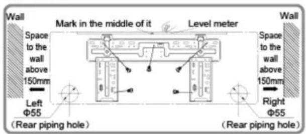
18K:

24K:

Drill a piping hole of diameter 55 or 70 at the chosen location for the outlet pipe. To allow for proper drainage, the piping hole in the wall must slant slightly downwards to the outdoor side, with a gradient of 5 - 10^ .
| Piping hole Model | |
| ∅ 55 Cooling | capacity < 6000 W |
| ∅ 70 Cooling | capacity > 6000W |
N.B.:
• Take the necessary safety measures when drilling the hole and do not allow dust to enter.
- The plastic wall plugs are not supplied but must be purchased on site.

| Indoors | |
| Outdoors |
Step four: outlet pipe
The pipe can be brought out in various different directions: right, rear right, left or rear left.
Once you have selected the direction of the outlet (left or right), drill the corresponding hole at the bottom.

Step five: connect the indoor unit pipe
Position the pipe joint in the corresponding bellmouth.
Pre-tighten the union nut by hand.
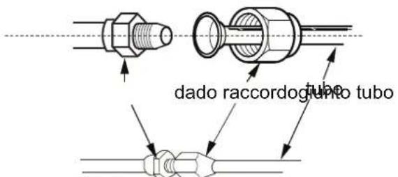
Adjust the torque according to the following table. Position the open-end spanner on the pipe joint and position the torque wrench on the union nut. Tighten the nut with the wrench.

Wrap the indoor pipe and the joint of the connecting pipe with an insulating tube. Then wrap with tape.
Step six: install the condensate drain pipe
Connect the drain pipe to the outlet pipe of the indoor unit.
Bind the joint with tape.

- Add an insulating tube to the indoor drain pipe to prevent condensation.
• The plastic wall plugs are not supplied.
-
Open the panel. Remove the screw that secures the small panel covering the terminal board.
-
Insert the indoor and outdoor unit connecting cable into the rear hole corresponding to the terminal block. Then pull it out of the front.
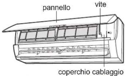

- Remove the cable clip. Connect the power cable to the terminal block according to colour. Tighten the screw and secure the power cable with the clip.

- Reposition the terminal block cover and tighten the screws.
- Close the panel.
N.B.:
- All wiring must be connected as shown on the unit's wiring diagram.
All indoor and outdoor unit cables must be connected by a qualified technician.
- If the power cable is not long enough, contact the supplier for a new one. Do not attempt to extend it yourself.
- For air conditioners equipped with a plug, the plug must be easily accessible upon completion of installation.
- For air conditioners without a plug, install a circuit breaker on the line. The circuit breaker must be single-pole and the contact gap must be greater than 3mm.
Step eight: bind the pipes
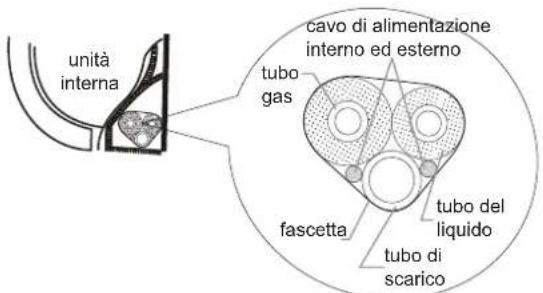
- Bind together the connecting pipe, the power cable and the drain pipe with binding tape.
-
Reserve a section of the drain pipe and power cable for installation when binding. When you have bound up to a certain point, separate the indoor power cable and then the drain pipe.
-
Bindthemevenly.
-
The liquid pipe and gas pipe must be bound, respectively at the end.
N.B.:
The power cable and signal control cable must not be rolled or coiled.
The drain pipe must be bound at the bottom.
Step nine: hang the indoor unit
- Insert the bound pipes into the wall pipe and route them through the hole in the wall.
- Hang the indoor unit on the wall-installation plate.
- Fill the gap between the pipes and the hole in the wall with sealant.
- Secure the wall pipe.
- Check that the indoor unit is securely installed and flush against the wall.
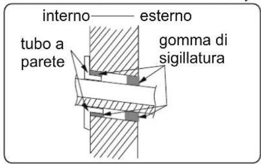

- Avoid bending the drain pipe too much in order to prevent clogging.
Outdoor unit installation
Step one: secure the outdoor unit support
-
Choose a location for the unit according to the structure of the house.
-
Use expansion screws to secure the outdoor unit support in the chosen position.
N.B.:
• Take the appropriate safety measures when installing the outdoor unit.
• Make sure that the bracket can support at least four times the weight of the unit.
- The outdoor unit must be connected at least 3 cm above the ground in order to install the drain joint.
- Units with a cooling capacity of 2300 W – 5000 W require 6 expansion screws; units with a cooling capacity of 6000 W – 8000 W require 8 expansion screws; units with a cooling capacity of 10000 W – 16000 W require 10 expansion screws.

natural_image
Line drawing of a rectangular air conditioner unit with grid grille and base-mounted base (no text or symbols)at least 3 cm above the ground
Step two: install the drain joint
-
Connect the outdoor drain joint into the hole on the chassis, as shown below.
-
Connect the drain hose into the drain hole.
Step three: secure the outdoor unit
-
Position the outdoor unit on the support.
-
Secure the foot holes of the outdoor unit with bolts.

fori piedini
Step four: connect the indoor and outdoor pipes
-
Remove the screw on the right-hand handle of the outdoor unit and remove the handle.
-
Pre-tighten the union nut by hand.

impugnatura
| vite | screw |
| impugnatura | handle |
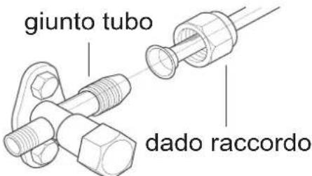
-
Remove the screw cap of the valve and position the pipe joint in the bellmouth of the pipe.
-
Tighten the union nut with the wrench according to the following table.

| Hex nut diameter Tightening torque(Nm) | |
| _6.35 | 15 – 20 |
| _9.52 | 30 – 40 |
| _12.7 | 45 – 55 |
| _15.88 | 60 – 65 |
| valvola del liquido liquid valve | |
| tubo del liquido liquid pipe | |
| tubo del gas gas pipe | |
| valvola del gas gas valve |
Step five: connect the outdoor electrical cable
- Remove the wire clip. Connect the power cable and the signal control cable (only for cooling and heating units) to the wiring terminal according to colour. Secure them with the screws.
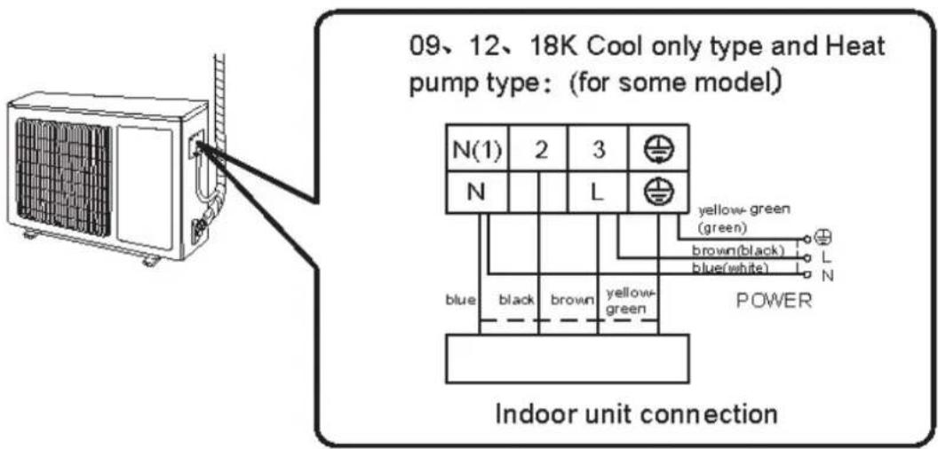
- Secure the power cable and the signal control cable with the clip (only for cooling and heating units).
N.B.: • Once you have tightened the screw, pull on the power cable gently to check it is secure.
- Never cut the power cable to extend or reduce the distance.
Step six: tidy up the pipes
- The pipes should be routed along the wall, bent only as much as is necessary and, if possible, hidden from view. Minimum pipe bending radius: 10 cm.
- If the outdoor unit is higher than the hole in the wall, you must create a U-bend in the pipe before it enters the room to prevent rain from getting into the room.

- The height of the drain pipe through the wall must not be greater than the height of the hole for the indoor unit's outlet pipe.

- Slant the drain pipe slightly downwards. The drain pipe must not be bent, raised, twisted, etc.

natural_image
Simple line drawing of a rectangular container with a checkmark above it and a coiled cable extending from its side (no text or symbols)• To ensure uniform drainage, the water outlet must not be placed in water.

Using the vacuum pump
- Remove the valve caps of the liquid valve and gas valve and remove the nut of the refrigerant charge port.
- Connect the piezometer charge pipe to the refrigerant charge bore of the gas valve. Then connect the other charge pipe to the vacuum pump.
- Open the piezometer completely and let it run for 10 – 15 minutes to check if the pressure of the piezometer remains at -0.1 MPa.
- Close the vacuum pump and maintain this condition for 1 – 2 minutes to check if the pressure of the piezometer remains at -0.1 MPa. If the pressure falls, there may be a leak.

- Remove the piezometer. Fully open the plunger of the liquid valve and gas valve with the inner hex key.
- Tighten the screw caps of the valves and refrigerant charge port.
- Reinstall the handle.
Leak detection
Check for leaks using a leak detector. If you do not have a leak detector you can use soapy water.
Post-installation checks
| Checks Possible fault | |
| Has the unit been installed securely? The unit could fall, move or produce excessive noise. | |
| Is the thermal insulation of the pipes sufficient? | Risk of condensation and dripping water. |
| Does the water drain properly? Risk of condensation and dripping water. | |
| Does the supply voltage match the voltage indicated on the data plate? | Risk of malfunction or damage to components. |
| Have the piping and electrical wiring been installed correctly? | Risk of malfunction or damage to components. |
| Has the unit been properly earthed? Risk of electric leakage. | |
| Does the power cable meet requirements? Risk of malfunction or damage to components. | |
| Are there any obstructions at the air inlet or outlet? The cooling (heating) capacity may be insufficient. | |
| Have the dust and other particles produced during installation been removed? | Risk of malfunction or damage to components. |
| Are the gas valve and liquid valve of the connecting tube fully open? | The cooling (heating) capacity may be insufficient. |
Connect the power and press the ON/OFF button on the remote control to start operation. Press the MODE button to select AUTO, COOL, DRY, FAN and HEAT mode and check the air conditioner operates normally. If the ambient temperature is below 16°C, the air conditioner will be unable to start cooling.
APPENDICES
Piping configuration
-
Standard connecting tube length: 5 m.
-
Minimum connecting tube length: 3 m.
-
Maximum connecting tube length and maximum height difference:
| Capacity | Maximum connecting tube length | Maximum height difference |
| 9000Btu/h | 15 | 10 |
| 12000Btu/h | 20 | 10 |
| 18000Btu/h | 20 | 10 |
Warning! Note the additional charge on the data plate affixed to the outdoor unit.
Additional oil and refrigerant charging
- If the length of the connecting pipe is increased by 10 m compared to the standard length, add 5 ml of refrigeration oil for every 5 m of pipe added.
- Method for calculating the amount of additional refrigerant charge (liquid pipe): amount of additional refrigerant charge = additional length of liquid pipe x additional amount of refrigerant charge per metre.
| Connecting pipe diameter Additional refrigerant | ||
| Liquid pipe (mm) Gas pipe (mm) (g/m) | ||
| Φ6.35 9.52 or | 12Φ Φ | 20 |
| Φ6.35 15.88 | Φ | 50 |
Procedure for extending the piping
N.B.:
Improper extension of piping is the main cause of refrigerant leaks. Proceed as shown below:
1. Cut the pipe
- Check the length of the pipe based on the distance between the indoor unit and outdoor unit.
- Cut the required pipe using a pipe cutter.
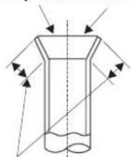
5. Expand the port
Expand the port using a pipe expander.

- Remove burrs with a file, ensuring they do not go into the pipe.

3. Secure an insulating tube
4. Install a union nut
- Remove the union nut on the indoor connecting pipe and outdoor valve. Install the union nut on the pipe.
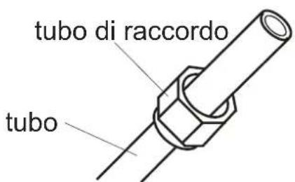
- "A" varies according to diameter:
| Outdoor diameter (mm) | A (mm) | |
| Max. | Min. | |
| 6.35 (1/4") 1.3 0.7 | ||
| 9.52 (3/8") 1.6 1.0 | ||
| 12.7 (1/2") 1.8 1.0 | ||
| 15.88 (5/8") 2.4 2.2 | ||
6. Inspection
Check the quality of the expanded port. If defective, expand the port again following the procedure described above.
superficie liscia
natural_image
Diagram of a cylindrical object with internal flow arrows indicating direction (no text or symbols)The unit contains R410A, a fluorinated greenhouse gas with global warming potential (GWP) = 2087.50. Do not release R410A into the atmosphere.

- USER AND INSTALLATION MANUAL
- Contents
- Information for use
- Guide to the remote control and display
- Maintenance
- Troubleshooting
- Installation instructions
- Installation
- Testing and operation
- Appendices
- INFORMATION FOR CORRECT DISPOSAL OF THE PRODUCT IN ACCORDANCE WITH THE EUROPEAN DIRECTIVE 2012/19/EU
- INFORMATION FOR USE Precautions for use
- WARNING
- Operating limits
- Description of components
- Indoor unit
- Outdoor unit
- GUIDE TO THE REMOTE CONTROL AND DISPLAY Remote control buttons
- Getting to know the display icons
- Getting to know the remote control buttons
- N.B.:
- ON/OFF button
- MODE button
- +/- Button
- FAN button
- SWING button
- SLEEP button
- TIMER mode
- Getting to know the button combination functions
- Remote control button lock function
- Switching temperature display
- Operating guide
- Replacing the remote control batteries
- INFORMATION FOR THE CORRECT DISPOSAL OF BATTERIES IN ACCORDANCE WITH EUROPEAN DIRECTIVE
- 2006/66/EC
- Emergency operation
- Care and cleaning
- Cleaning the casing of the indoor unit
- Cleaning the filters
- Open the panel
- Remove the filters
- Clean the filters
- Refit the filters
- WARNING!
- Before-use checks
- After-use checks
- Possible faults and solutions
- Analysing faults and solutions
- Error codes
- INSTALLATION INSTRUCTIONS Installation diagrams
- Electrical connection requirements
- Safety precautions
- Earthing
- Indoor unit installation
- Step two: mount the wall-installation plate
- Step three: drill the hole for the piping
- Step four: outlet pipe
- Step five: connect the indoor unit pipe
- Step six: install the condensate drain pipe
- Step eight: bind the pipes
- Step nine: hang the indoor unit
- Outdoor unit installation
- Step one: secure the outdoor unit support
- Step two: install the drain joint
- Step three: secure the outdoor unit
- Step four: connect the indoor and outdoor pipes
- Step five: connect the outdoor electrical cable
- Step six: tidy up the pipes
- Using the vacuum pump
- Leak detection
- Piping configuration
- Procedure for extending the piping
- Cut the pipe
- Expand the port
- Secure an insulating tube
- Install a union nut
- Inspection
Brand : ARGO
Model : WALL 18000 UI
Category : Air Conditioning