
AWIAS12DC - Air Conditioning ARGO - Free user manual and instructions
Find the device manual for free AWIAS12DC ARGO in PDF.
| Product type | Reversible split system air conditioner |
| Brand | ARGO |
| Model | AWIAS12DC |
| Power supply | 220-240 V ~ 50 Hz single phase |
| Refrigerant | R410A, PRG 2087.5 |
| Operating modes | Cooling, heating, dehumidification, ventilation, automatic |
| Fan speed | Automatic, high, medium, low |
| Special functions | Night/Eco, High Power, I-Feel (remote control sensor), TiO₂ filter, 24h timer, Holiday Timer |
| Air flow adjustment | Manual horizontal louvers, motorized vertical flap with 6 positions + oscillation |
| Remote control | With display, sensor selector, AAA 1.5V batteries (2 pcs) |
| Filters | Washable air filter + optional activated carbon filter |
| Emergency operation | Selector on indoor unit (OFF, COOL, HEAT) |
| Maintenance | Filter cleaning every 2 weeks, body with soft cloth |
| Self-diagnosis | Error codes E0 to E8 indicated by LEDs |
| Protection | Automatic shutdown in case of failure, restart after 3 minutes after power cut |
| Safety | Do not use flammable liquids, installation by professional, grounding mandatory |
| Repairability | Parts available from dealer, replaceable activated carbon filter |
| Standards | CE, RoHS2, Low Voltage 2006/95/EC, EMC 2004/108/EC |
| Disposal | Do not dispose with household waste, recycle according to WEEE directive |
Frequently Asked Questions - AWIAS12DC ARGO
User questions about AWIAS12DC ARGO
0 question about this device. Answer the ones you know or ask your own.
Ask a new question about this device
Download the instructions for your Air Conditioning in PDF format for free! Find your manual AWIAS12DC - ARGO and take your electronic device back in hand. On this page are published all the documents necessary for the use of your device. AWIAS12DC by ARGO.
USER MANUAL AWIAS12DC ARGO
If you have problems or questions concerning your Air Conditioner, you will need the following information. Model and serial numbers are on the nameplate on the bottom of the cabinet.
Model No.
Serial No.
Date of purchase
Dealer's address
Phone number
ALERT SYMBOLS
The following symbols used in this manual, alert you to potentially dangerous conditions to users, service personnel or the appliance:

WARNING
This symbol refers to a hazard or unsafe practice which can result in severe personal injury or death.

CAUTION
This symbol refers to a hazard or unsafe practice which can result in personal injury or product or property damage.
NOTE
This air conditioner is equipped with cooling, drying, heating and fan only functions.
Details on these functions are provided below; refer on these descriptions when using the air conditioner.
DECLARATION OF CONFORMITY
This product is marked C as it satisfies Directives:
- Low voltage no. 2006/95/EC (Standard: EN60335-2-40:2003 (incl. Corr.: 2006) + A11:2004 + A12:2005 + A13:2012 + A1:2006 + A2:2009 con EN 60335-1:2002 + A11:2004 + A12:2006 + A2:2006 + A13:2008 + A14:2010 + A15:2011).
Electromagnetic compatibility no. 2004/108/EC, 92/31 EEC and 93/68 EEC. (Standard: EN55014-1 (2006) + A1(2009) + A2(2011), EN 55014-2 (1997) + A1(2001) + A2 (2008), EN 61000-3-2 (2006) + A1(2009) + A2(2009), EN 61000-3-3 (2008)
RoHS2 no.201/65/EU
Regulation (EU) no. 206/2012, of 6 march 2012, concerning the specifications for ecodesign requirements of air conditioners and fans.
Regulation (EU) no. 626/2011, of 4 may 2011, concerning the labeling indicating the energy consumption of air conditioners.
This declaration will become void in case of misuse and/or non observance though partial of manufacturer's installation and/or operating instructions.
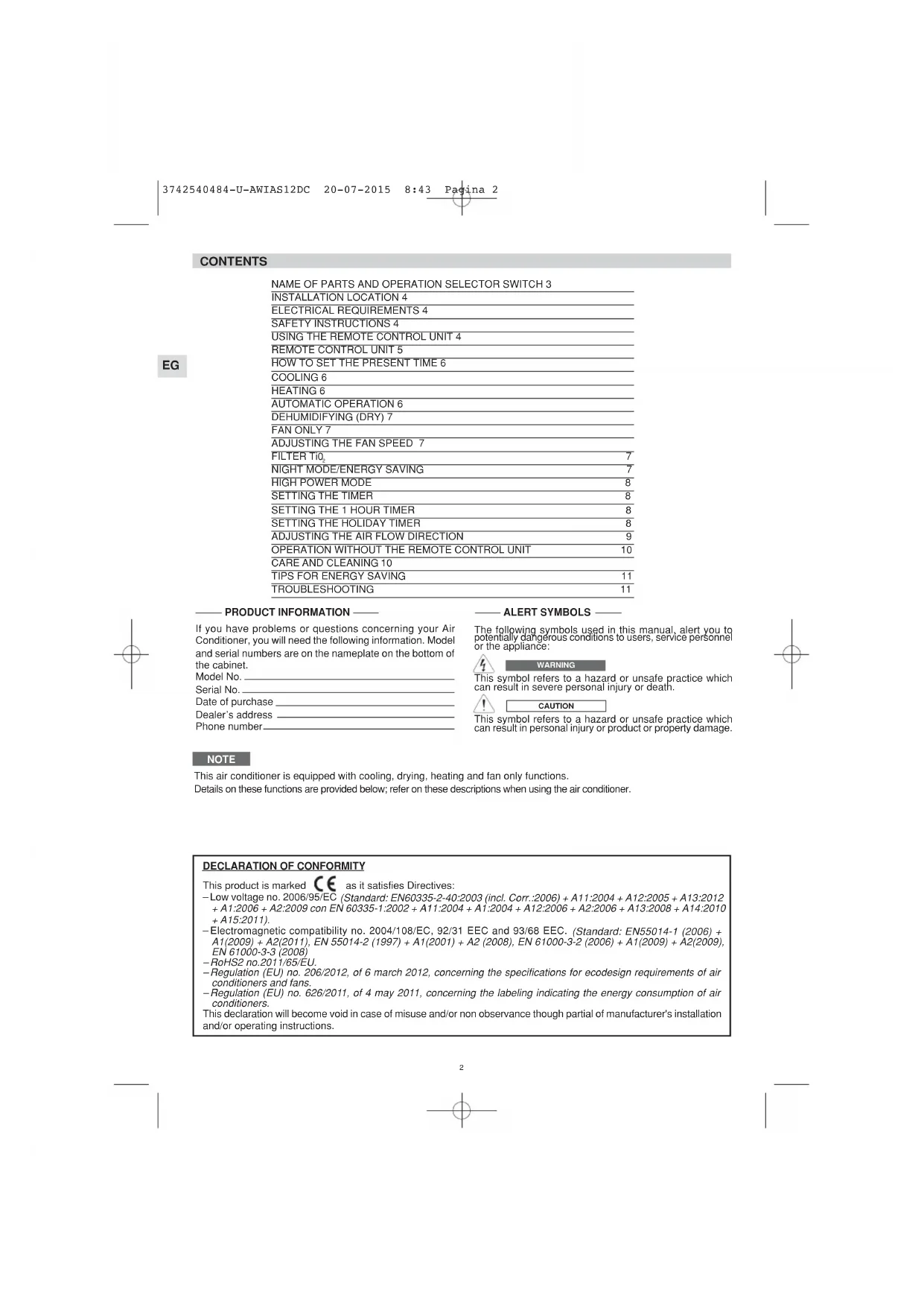
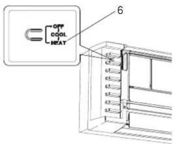
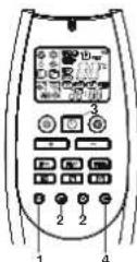
NAME OF PARTS AND OPERATION SELECTOR SWITCH
EG
- Remote control unit.
- Remote control sensor: Detects the room temperature around the remote control unit, the air conditioner is controlled accordingly.
- Air outlet: Conditioned air is blown out of the air conditioner through the air outlet.
- Air intake: Air from the room is drawn into this section and passes through air filter which removes dust.
- Remote control receiver: This section picks up infrared signals from the remote control unit (Transmitter).
- Operation selector (without remote control): Push the button to walk through the operation modes (OFF, COOL and HEAT)

WARNING
The OFF position does not disconnect the power. Use the main power switch to turn off power completely.
- OPERATION lamp: This lamp lights up during operation. It blinks once to announce that the remote control signal has been received and stored.
- STANDBY lamp: This lamp lights up when the air conditioner is connected to the power and ready to receive the remote control command.
- TIMER lamp: This lamp lights up when the system is being controlled by the timer.
NOTES
It is possible to set the air conditioner in order to let the OPERATION, TIMER and STANDBY lamps always OFF, even during operation.
Be sure that CLEAN/FILTER TiQ mode is OFF. Press contemporary the IFEEL and FAN buttons on the remote control unit for more than 5 seconds.
Repeat the same procedure to set again the normal operation conditions.
In case of troubleshooting the air conditioner diagnostic system activates the lamps accordingly, even if they are set to OFF. See paragraph TROUBLESHOOTING for further details.
MULTISPLITSYSTEM only
The blinking of TIMER and STANDBY lamps and OPERATION lamp ON, indicates that:
- Indoor unit has not been addressed.
- Heating mode has been selected, when the system was in cooling mode, or vice versa.
Select the correct mode, compatible with the system.
INSTALLATION LOCATION
- We recommend this air conditioner to be installed properly by qualified installation technicians in accordance with the Installation Instructions provided with the unit.

WARNING
EG
- Do not install this air conditioner where there are fumes or flammable gases, or in an extremely humid space such as a green house.
- Do not install the air conditioner where excessively high heat-generating objects are placed.
- Do not install the air conditioner where the atmosphere is extremely damp or humid (e.g. greenhouse or laundry) it could be wetted by drops of water (i.e. in laundries).
- To protect the air conditioner from heavy corrosion, avoid installing the outdoor unit where salty sea water can splash directly onto it or in sulphurous air near a spa.
ELETRICAL REQUIREMENTS
Before installation, check that the voltage of the electric supply in your home or office is the same as the voltage shown on the nameplate.
- All wiring must conform to the local electrical codes. Consult your dealer or a qualified electrician for details.
Each unit must be properly grounded with a ground (or earth) wire or through the supply wiring.
- Wiring must be done by a qualified electrician.
SAFETY INSTRUCTIONS
- Read this booklet carefully before using this air conditioner. If you still have any difficulties or problems, consult your dealer for help.
- This air conditioner is designed to give you comfortable room conditions. Use this only for its intended purpose as described in this Instruction Manual.

WARNING
- Never use or store gasoline or other flammable vapor or liquid near the air conditioner. It is very dangerous.
- Never install electrical equipment, which is not protected with IPX1 protection (protection against vertical water drop), under the unit.
- The manufacturer assumes no responsibilities if the safety regulations or local codes are not observed.

CAUTION
- Never use the power main switch to start or stop the air conditioner: always use the ON/OFF button on the remote control unit or the selector switch on the unit.
- Do not let children play with the air conditioner.
- Do not cool the room too much if babies or invalids are present.
- This air conditioner is not intended for use by persons (including children) with reduced physical, sensory or mental capabilities, or lack of experience and knowledge, unless they have been given supervision or instruction concerning use of the air conditioner by a person responsible for their safety.
USING THE REMOTE CONTROL UNIT
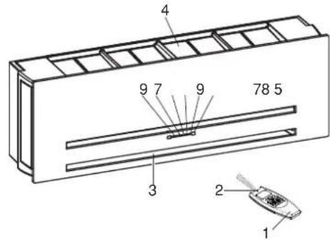
HOW TO INSTALL BATTERIES
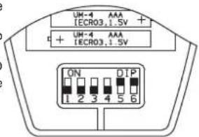
- Remove the lid in the rear part of the remote control unit and check the settings of the four microswitches as shown below: PLEASE. SEE THE END
- Insert two AAA alkaline batteries of 1.5 V-DC making sure that point in the direction marked in the battery compartment. The displayed time flashes. Press the SEL TYPE button.
Remote controller is now ready for operation. - The batteries last average more than six months, anyway it depends on how much you use the remote control unit. Remove the batteries if you do not use the remote control unit for more than one month. Replace the batteries when the remote control unit lamp fails to light, or when the air conditioner does not receive the remote control unit signals.
- The batteries of the remote control contain polluted substances. Exhausted batteries must be disposed according to the laws in force.
NOTE
IF YOU INSTALL MORE THAN ONE INDOOR UNIT IN THE SAME ROOM:
It is possible to utilise only one remote control for all the units.
On the contrary, if you want to address each remote control to its unit, follow the procedure"Remote control unit/indoor unit address" (see Installation Instructions).
TEMPERATURE SENSOR SELECTOR
Under normal conditions the room temperature is detected and checked by the temperature sensor placed in the remote controller (IFEEL icon displayed). This function is designed to provide a comfortable room temperature by transmitting the temperature control command from the location next to you. When using this function, the remote, control should always be pointed at the air conditioner, therefore it should be placed in a position in which it is visible by the indoor unit (for example, do not put it in a drawer).
- It is possible to disable the remote controller room sensor pressing the I FEEL button. In this case the I FEEL icon on the remote controller display lights off and only the sensor placed in the air conditioner becomes active.
NOTE
The remote control unit transmits signals to the indoor unit each time you press a key and at any temperature change detected by the IFEEL sensor. In case of troubles (low batteries, remote control placed in a position not visible by the indoor unit,...) room temperature control is automatically switched to the sensor of the indoor unit. In this case, the temperature around the remote control unit may differ from the temperature detected in the air conditioner position.
When using the remote control unit, always point the unit transmitter head directly at the air conditioner receiver.
HOW TO TURN ON THE AIR CONDITIONER
Press the ON/OFF button to turn the air conditioner on. The operation lamp will light up, indicating the unit is in operation.
REMOTE CONTROL UNIT
DISPLAY
Information is displayed when the remote controller is switched on. If switched off, only the operating mode, the room temperature and the clock are shown
IFEELmodeIsactive
(remote controller
sensor active)
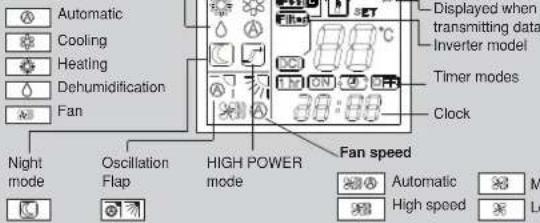
Operation mode
Room
temperature
Set point
temperature
MODE SELECTOR BUTTON
Press this button to modify the air conditioner mode.
(cooling)
The air conditioner makes the room cooler.
△ (dry)
The air conditioner reduces the humidity in the room.
(automatic)
When this setting is selected, the air conditioner calculates the difference between the thermostat setting and the room temperature and automatically switches to the "cool" or "heat" mode.
(tan)
The air conditioner works only as a circulation fan.
TEMPERATURE SETTING BUTTONS
- (cooler)
Press this button to decrease the set temperature.
- (warmer)
Press this button to increase the set temperature.
"FAN - BUTTON (fan speed)
图
Fan speed is automatically
selected by the microcomputer.
High speed.
Medium speed.
Low speed.
NIGHT/ECO BUTTON
Press this button in order to select the NIGHT/ECO mode.
"HIGH POWER" BUTTON
Press this button in order to select the HIGH POWER mode.
CLOCK AND TIMER SETTING BUTTON
Press this button in order to
- set the clock
set the ON/OFF timer
For details refer to paragraphs "SETTING
THE HOUR" and "SETTING THE TIMER".
SENSOR
A temperature sensor inside the remote control unit detects the room temperature.
TRANSMITTER
When you press the buttons of the remote control unit, the mark = appears on the display to transmit the setting changes to the receiver in the air conditioner.
MODE SELECTOR BUTTON
Press this button to modify the air conditioner mode.

(heating)
blinking
or fixed
The air conditioner makes the room warmer.

ON/OFF BUTTON
(automatic)
When this setting is selected, the air conditioner calculates the difference between the thermostat setting and the room temperature and automatically switches to the "cool" or "heat" mode.
This button turns the air conditioner ON and OFF.
FLAP BUTTON
Press this button in order to select the desired function.
TIMER SELECTION BUTTON
Fixed: six position
Continuous oscillations
Automatically oscillations
IFEELIFEELCSENSORSELECTOR
Press this button to modify the active setting for room temperature detection (from remote controller to air conditioner and viceversa).
CLEAN/FILTER TIO-MENU BUTTON
Press this button in order to select the mode or to enter the functions menu.
Press this button to select the type of timer to activate. For details refer to paragraph "SETTING THE TIMER".
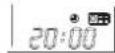
HOW TO SET THE PRESENT TIME
- Press the button ST three times. The time indication alone flash
- Press the H button until the present time hour is displayed. Press the M button until the present time minutes are displayed. The display will automatically stop flashing.
EG
COOLING
NOTE
Verify that the unit is connected to the main power and the STANDBY lamp is light up.
1.Set the selector to COOL (symbol on the display).
2. Press the +/- buttons (temperature selection) to set the desired temperature (the temperature range is between 32^ max. and 10^ min.).

THE DISPLAY SHOWS THE SELECTED TEMPERATURE.

AFTER.5 SECONDS FROM THE REQUIRED TEMPERATURE SETTING THE DISPLAY WILL SHOW THE ROOM TEMPERATURE AGAIN.
- Press the FAN button to select the fan speed.
HEATING
1.Set the selector to HEAT (symbol on the display.
2. Press the +/- buttons (temperature selection) to set the desired temperature (the temperature range is between 32^ max. and 10^ min.).

THE DISPLAY SHOWS THE SELECTED TEMPERATURE.

AFTER 5 SECONDS FROM THE REQUIRED TEMPERATURE SETTING THE DISPLAY WILL SHOW THE ROOM TEMPERATURE AGAIN.
- Press the FAN button to select the fan speed.
NOTE
For several minutes after the start of heating operation, the indoor fan will stop until the indoor heat exchanger coil has warmed up sufficiently. This is because the COLD DRAFT PREVENTION SYSTEM is operating. During this period, the STANDBY lamp remains lit.
DEFROSTING OF OUTDOOR UNIT HEAT EXCHANGER
When the outdoor temperature is low, frost or ice may appear on the heat exchanger coil, reducing the heating performance. When this happens, a protection function for the heat exchanger defrosting is activated. During this function operation, the fan of the indoor unit stops. Heating operation restarts after several minutes. (This interval will vary slightly depending on the room and outdoor temperature).
HEATING PERFORMANCE
A heat pump conditioner heats a room by taking heat from outside air. The heating efficiency will fall off when the outdoor temperature is very low. If enough heat is not obtained with this air conditioner, use another heating appliance in conjunction with it.
AUTOMATIC OPERATION
1.Set the or selector to AUTO (symbol on the display; also the symbol or remains displayed).
2. Press the +/- buttons (temperature selection) to set the desired temperature (the temperature range is between 32^ max. and 10^ min.).

HE DISPLAY SHOWS THE SELECTED TEMPERATURE.

AFTER.5 SECONDS FROM THE REQUIRED TEMPERATURE SETTING THE DISPLAY WILL SHOW THE ROOM TEMPERATURE AGAIN.
When this setting is selected, the air conditioner calculates the difference between the thermostat setting and the room temperature and automatically switches to the COOL or HEAT mode as appropriate, regardless of the symbol displayed.
- Press the FAN selector button to the setting you want.
Example of operation diagram in the (Auto) mode with the set room temperature at 23^
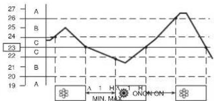
NOTE
The air conditioner changes the operation mode (from cool to heat or vice versa, if one of the following conditions occurs:
- ZONE A: changes if the difference between the room temperature and the temperature set on the remote control unit is at least 3^ .
- ZONE B: changes if the difference between the room temperature and the temperature set on the remote control unit is at least 1^ , one hour after the compressor stop.
- ZONE C: never changes if the difference between the room temperature and the temperature set on the remote control unit is no more than 1^ .
AUTOMATIC OPERATION IN MULTISPLIT CONFIGURATION
When the air conditioning system configuration is multisplit and there is more than one indoor unit connected, the automatic mode operates as follows:
the first unit that switches on the system also decides the operation mode (cooling or heating) for all the other units that will be switched on after the first one;
- when the system has been switched on in cooling mode and one unit is activated in heating mode, an error will be signaled for this unit (wrong operating mode). If the same unit is switched on in "automatic" mode and the desired temperature is lower than the detected ambient temperature, the unit will operate in cooling mode, like the other units of the system; on the contrary, if the desired temperature is higher than the detected one, the unit will operate in fan mode;
- when the system has been switched on in heating mode and one unit is activated in cooling mode, an error will be signaled for this unit (wrong operating mode). If the same unit is switched on in "automatic" mode and the desired temperature is higher than the detected ambient temperature, the unit will operate in heating mode, like the other units of the system; on the contrary, if the desired temperature is lower than the detected one, the unit will operate in fan mode.
DEHUMIDIFYING (DRY)
1.Set the button to DRY. The icon is displayed.
2. Press the +/- buttons (temperature selection) to set the desired temperature (the temperature range is between 32^ max. and 10^ min.).

THE DISPLAY SHOWS THE SELECTED TEMPERATURE.

AFTER 5 SECONDS FROM THE REQUIRED TEMPERATURE SETTING THE DISPLAY WILL SHOW THE ROOM TEMPERATURE AGAIN.
NOTE
- Use DRY operation when you want to reduce the humidity in the room.
- Once the room temperature reaches the set level, the unit repeats the cycle of turning on and off automatically.
During DRY operation, the fan speed is automatically set (Remote control lamp is ON) to prevent overcooling. - Dry operation is not possible if the indoor temperature is 10^ or less.
FAN ONLY
If you want to make air circulate without any temperature control, press button until only the fan symbol appears on the display.
ADJUSTING THE FAN SPEED
AUTOMATIC
Simply set the FAN selector to the position. A microcomputer automatically controls the fan speed when the AUTO mode is selected. When the air conditioner starts operating, in heating or cooling, the fan speed varies (high - medium - low - very low) according to the thermal load of the room.
NOTE
The automatic speed is not available in FAN ONLY mode.
MANUAL
If you want to manually adjust speed just set the FAN selector as desired.
High speed Me speed Low speed
CLEAN/FILTER TiO2 (if present)
Pressing the button (symbol on the display) the filtering system with titanium dioxide is activated; this is very effective to prevent bad odours and to eliminate bacteria and micro-organisms.
NOTE
The filter is active only if the internal fan is operating.
This mode enables you to save energy.
- Set the or selector to cool, dry or heat.
- Press the button.
- The mark appears on the display. Press the button again to release the function.
What does the NIGHT mode mean?
When you select the NIGHT mode, the air conditioner will modify automatically the set temperature after 60 minutes. This enables you to save energy without sacrificing your comfort.
OPERATING MODE SEIT TEMPERATURE CHANGE
Heating Lowered by 2^
Cooling and Dry Raised by 1^
NOTA
During the NIGHT mode the internal fan speed is automatically lowered and reduces the noise.
HIGH POWER MODE
When this mode is active the internal fan speed is set automatically and the air conditioner operates at the maximum power in the selected operating mode (cooling or heating).
NOTE
EG During the high power operation the room temperature could not correspond to the set temperature.
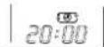
SETTING THE TIMER
- Press the ST button once.
The ON and time indications flash. - Press the H button until the designed hour is displayed.
Press the M button until the designed minutes are displayed. The display will change automatically back to show the present time after 10 sec. - Press the ON/OFF button to start the air conditioner.
- Press the button to activate the ON timer.
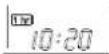
- Press the ST button twice. The OFF and time indications flash.
- Press the H button until the designed hour is displayed.
Press the M button until the designed minutes are displayed. The display will change automatically back to show the present time after 10 sec. - Press the ON/OFF button to start the air conditioner.
- Press the button two times to activate the OFF timer.
C) HOW TO SET A PROGRAM FOR DAILY ON/OFF OPERATION (OR VICEVERSA)
- Set the timer ON/OFF as shown in A) and B).
- Press the ON/OFF button to start the air conditioner.
- Press three times the button to activate the DAILY timer.
NOTE
After timer setting, press ST button in order to check the ON/OFF setting time.
SETTING THE 1 HOUR TIMER
This function causes the unit to operate for one hour at the set conditions, regardless of whether the unit is on or off.
TIMER SETTING PROCEDURE.
Press four times the button.The 1 HOUR TIMER mark will appear on the display.
CANCELLATION PROCEDURE
- Press the ON/OFF button to turn the air conditioner off.
- Wait for the indoor unit to stop operating.
- Press the ON/OFF button again to turn the air conditioner on.
SETTING THE HOLIDAY TIMER
The Holiday Timer function allows you to activate the indoor unit (either it is the only one of a monosplit system or one unit of a multisplit system), with a delay up to 99 days you can set for the Daily Timer, On Timer, Off Timer functions (not available for 1 HOUR TIMER) already explained in this manual.
With this function you can set the air conditioner to be switched on again after a long week end, a holiday of one week or more, ecc...
To activate this function you have to follow the following steps in order :
- Keep pressed the button "TIMER SELECTION" of the remote control unit (clock figure) for more than 6~7 seconds. In this way you enter the menu to select the number of days of delay.
- Select the desired timer (Daily Timer, On Timer, Off Timer) pressing on the same button "TIMER SELECTION".
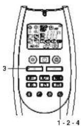
- Set the desired number of days of delay using the button "4."
- Keep pressed again the button "TIMER SELECTION" for more than 6~7 seconds. You enter again the normal menu of the remote control unit.
At this point, the symbol of the desired timer will flash and the selected timer will be activated only after the set number of delay days.
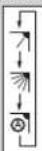
ADJUSTING THE AIR FLOW DIRECTION
HORIZONTAL (manual)
The horizontal air flow can be adjusted by moving the vertical vanes to the left or right, as indicated in the following figures.
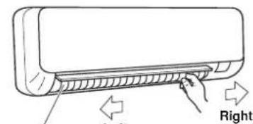
Vertical vane
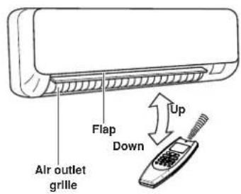
VERTICAL (with remote control unit)
Make sure that the remote control unit has been turned on. Press the FLAP button to select the flap function
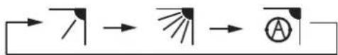
Fixed:
six
position
Continuous
oscillations
Automatical
oscillations
| FLAP | MODE |
| FLAP | MODE |
| FLAP | MODE |
NOTES
The flap automatically closes when the unit is off.
- When the unit starts in heating operation, the fan stops and the flap is in the 4 position (if automatic oscillation is selected) until the air being blown out of the unit begins to warm. Once the air warms up, the flap position and fan speed change to the settings specified with the remote control.

CAUTION
Do not move the flap with your hands when the air conditioner is running.

CAUTION
- Use the FLAP button on the remote control to adjust the position of the flap. If you move the flap by hand, the factual flap position and the flap position on the remote control may no longer match. If this should happen, shut off the unit, wait for the flap to close, and then turn on the unit again; the flap position will now be normal again.
- Do not have the flap pointed down during cooling operation. Condensation may begin to form around the air vent and drip down.
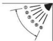
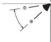
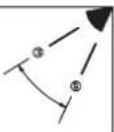
HOW TO ADJUST THE FLAP DIRECTION
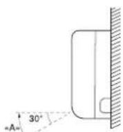
Zone «A»
for cooling and dehumidifying
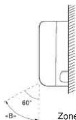
Zone B for heating

CAUTION
Set vertical vanes to the front position during COOLING/DRY operation if humidity is high. If the vertical vanes are set to the left-most or right-most position, condensation will form around the air outlet and drip off.
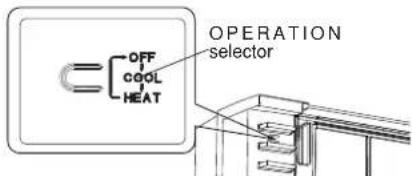
OPERATION WITHOUT THE REMOTE CONTROL UNIT
If you have lost the remote control unit or it has troubles, follow the steps below.
- WHEN THE AIR CONDITIONER IS STOPPED
If you want to turn on the air conditioner push the OPERATION selector with a pen to select the desired mode (COOL or HEAT).
EG
NOTE
The air conditioner will start in HIGH fan speed. The temperature setting is 25^ for cooling mode and 21^ for heating mode.
- WHEN THE AIR CONDITIONER IS RUNNING
If you want to turn off the air conditioner push the OPERATION selector with a pen until the OPERATION lamp is turned off.
NOTE
Power failure during operation.
In the event of power failure, the unit will stop. When the power is resumed, the unit will restart automatically after 3 minutes.
CARE AND CLEANING

WARNING
- Maintenance operations must be carried out by specially trained personnel.
- For safely, be sure to turn the air conditioner off and also to disconnect the power before cleaning.
- Do not pour water on the indoor unit to clean it. This will damage the internal components and cause an electric shock hazard.
CASING AND GRILLE (INDOOR UNIT)
Clean the casing and grille of the indoor unit with a vacuum cleaner brush, or wipe them with a clean, soft cloth. If these parts are stained, use a clean cloth moistened with a mild liquid detergent.
When cleaning the grille, be careful not to force the vanes out of place.

CAUTION
- Never use solvents, or harsh chemicals when cleaning the indoor unit. Do not wipe the plastic casing using very hot water.
Some metal edges and the vanes are sharp and may cause injury if handled improperly; be especially careful when you clean these parts. - The internal coil and other components of the outdoor unit must be cleaned every year. Consult your dealer or service centre.
AIR FILTER
The filter behind the front panel should be checked and cleaned at least once every two weeks.
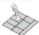
HOW TO REMOVE THE FILTER
The front panel is fixed to the unit with four magnets.
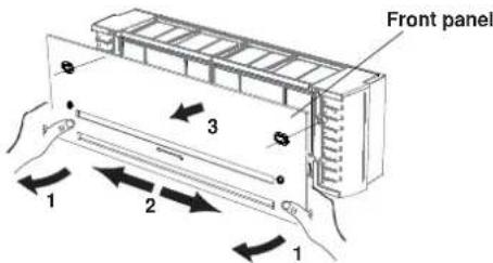
- Grasp both ends of the front panel and pull the lower part slightly towards you, in order to detach the magnets.
- Slide the panel to the right or left.
- Pull the panel again towards you in order to detach the upper magnets.
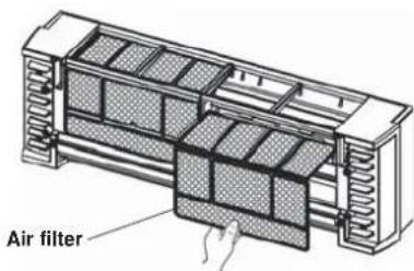
-
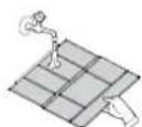
Push the filter up slightly, and then pull it down. Clean the air filter.
-
Replace the filter:
-
Slide the filter up into the unit and insert it in its place.
After installing the filter, replace the front panel.
FILTER CLEANING
Use a vacuum cleaner to remove light dust. If there is sticky dust on the filter, wash the filter in lukewarm, soapy water, rinse it in clean water, and dry it.
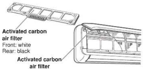
ACTIVATED CARBON AIR FILTER (ACCESSION)
The activated carbon air filter is to be added to the standard filter.
It is made of two layers:
- the first layer consists in a synthetic honey comb high efficiency media to remove the dust and purifying the air.
- the second layer in charcoal media deodorizing the ambient air.
NOTE
- The activated carbon air filters are in a polyethylene bag. 2. Open the bag just before installing the activated carbon air filters, otherwise, the deodorizing effect durability of the filter may be decreased.

WARNING
This activated carbon air filter cannot remove harmful gases or vapors nor ventilate air in the room. You must open doors or windows frequently when you use gas or oil heating appliances. Otherwise there is a risk of suffocation in an extreme case.
REPLACEMENT OF ACTIVATED CARBON AIR FILTER
The filter is disposable.
- Do not throw away the filter frame, if present.
The used filter cannot be reused even after cleaning up.
- Obtain the filters for replacement at your nearest dealer.
- Check the state of dirtiness at least once every two weeks.
- Replace the filter after six months' operation.
ACTIVATED CARBON AIR FILTER INSTALLATION PROCEDURE
The activated carbon air filter needs to be installed behind the air filter.
1.Remove the air filter.
2.Install the air clean filter in the position shown in the figure with the symbol "FRONT" facing you.
3.Reinstall the air filter.
TIPS FOR ENERGY SAVING
DO NOT:
- Block the air intake and outlet of the unit. If they are obstructed, the unit will not work well, and may be damaged.
- Let direct sunlight into the room. Use sunshades, blind or curtain.
DO:
Always try to keep the air filter clean. A clogged filter will impair the performance of the unit.
To prevent conditioned air from escaping, keep windows, doors and any other openings closed.
TROUBLESHOOTING

WARNING
- The use of portable telephones near the air conditioner may cause disturbance to its normal operation and must be avoided. In case abnormal operation is noticed, (OPERATION lamp lights, but the air conditioner will not run) to restore normal operation turn-off electric supply for about 3 minutes, by disconnecting the main switch or the wall plug, then start again the air conditioner.
If your air conditioner does not work properly, first check the following points before requesting service.
If it still does not work properly, contact your dealer or service centre.
Trouble: the air conditioner does not run at all.
Possible cause:
- Power failure.
- Leakage breaker tripped
- Operation button is OFF.
- Batteries in remote control unit have run down.
Remedy:
- Restore power.
- Contact service centre.
- Press the button again.
- Replace batteries.
Trouble: Poor cooling or heating performance.
Possible cause:
- Dirty or clogged air filters.
- Heat source or many people in room.
- Doors and/or windows are open
- Obstacle near air intake or air discharge port.
- The set temperature on the remote control unit is too high.
-
Outdoor temperature is too low (heat pump version).
-
Defrosting system does not work (heat pump version).
Remedy:
- Clean air filters to improve airflow.
- Eliminate heat source if possible.
- Shut them to keep the heat or cold out.
- Remove it to ensure good airflow.
- Set the right temperature on the remote control unit.
- Try to use a back-up heater.
- Consult your dealer.
Trouble: Clicking sound is heard from the air conditioner. Possible cause:
- During operation, any plastic parts may expand or shrink due to a sudden temperature change. In this event, a clicking sound may occur.
Remedy:
- This is normal, and the sound will disappear when an even temperature is settled.
AUTO-DIAGNOSIS TABLE
| ERROR | LEDS OPERATION | TIMER | STANDBY | POSSIBLE CAUSE SYSTEM | BEHAVIOUR SOLUTION | |
| E0 | • | F | F | Unit has not been addressed correctly. | Fan is stopped and flap is closed. The system restarts automatically as soon as the unit is addressed correctly. | Set the outdoor/indoor unit refrigerant circuit address (see Installation Instructions) |
| Operating mode selected is not compatible with the system (ex. heating mode has been selected, when the system was in cooling mode, or vice versa). | Select an available or compatible mode with the other units of the system. | |||||
| Fan is stopped and flap is closed. The system restarts automatically as soon as a correct operating mode is selected. | ||||||
| E1 | O O F | Error on the outdoor unit. Fan is stopped | and flap is closed. The system restarts automatically as soon as the problem on the outdoor unit is solved. | Check the error code using the appropriate LEDs on the PCB of the outdoor unit.Follow the indications of the diagnosis for the outdoor unit. |
O = LED OFF = LED ON F = Flashing LED
| ERROR | OPERATION | LEDS TIMER | STANDBY | POSSIBLE CAUSE SYSTEM | BEHAVIOUR SOLUTION | |
| E3 | FFF | Communication error between the out-door unit and the indoor unit | Fan is stopped and flap is closed after 30 seconds of missing communication. The system restarts automatically as soon as the communication is recovered. | Check that connections between C1 and C2 on outdoor and indoor terminal block are correct (C1 terminals connected together, C2 terminals connect- ed together). Check that a shielded communication cable has been used. Check that the dip-switch SW1 for com-munication address setting is in the correct position. Check that all earth cables are proper- ly connected to every terminal. Check that the shield of the communi-cation cable is properly connected to every terminal. Check the communication fuse on out- door and indoor unit. Check that the outdoor unit has power supply and that it is working. Check that all PCBs are powered on. Be sure that power supply has not been connected to the communication terminals. Check that there are no burnt signs on the PCBs, in particular close to commu-nication cables. Check that the fan motor is not dam- aged and it doesn't create short circuit on the indoor PCB. |
O = LED OFF = LED ON F = Flashing LED
| ERROR | LEDS OPERATION | TIMER | STANDBY | POSSIBLE CAUSE SYSTEM | BEHAVIOUR SOLUTION | |
| E4 | FFO | Defective or not connected indoor coil temperature sensor. | Fan is stopped and flap is closed.The system restarts automatically as soon as the sensor is repaired. | Check that the sensor is properly con- nected to the PCB as shown in the electrical wiring diagram. | ||
| Check that the sensor is not damaged and, if necessary, replace it. | ||||||
| E5 | FOF | Defective or not connected room air tem- perature/humidity sensor. | Fan is stopped and flap is closed.The system restarts automatically as soon as the sensor is repaired. | Check that the sensor is properly con- nected to the PCB as shown in the electrical wiring diagram. | ||
| Check that the sensor is not damaged and, if necessary, replace it. | ||||||
| E6 | OFF | Fan motor error. Fan is stopped and flap | is closed.The system restarts automatically after some seconds. | Check that the fan motor is properly connected to the PCB as shown in the electrical wiring diagram. | ||
| Check that the fan motor is not locked. | ||||||
| Check that the fan motor is not dam- aged and, if necessary, replace it. | ||||||
| E8 | OFO | Combination between outdoor unit and indoor units is not correct. | Fan is stopped and flap is closed. | Check that you have selected, during the installation of the system, a proper combination between outdoor unit and indoor units. | ||
| Check that none of the indoor units of the system has a communication error.If present, first solve this error. |
O = LED OFF = LED ON F = Flashing LED
NOTE: If the trouble is not solved with the above actions, contact your service centre.
EXPLANATION AND USE OF THE REMOTE CONTROL UNIT'S MICROSWITCHES
Switch 1 and 2: These switches are used to match the remote control with the specific internal units.
Switch 3 and 4: these switches have been provided for future use; they have no function today. Keep them in OFF position.
Switch 5 and 6: these switches set the remote control in WIRELESS or WIRED mode. Default position is ON (WIRELESS mode). For WIRED control, remove the batteries and set in OFF position.
EG
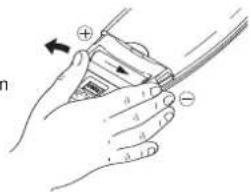
HOW TO REMOVE BATTERIES
- Remove the lid.
- Press the battery toward the negative end and lift it out by its positive end (as shown in the figure).
- Remove the other battery in the same way.

INFORMATION FOR CORRECT DISPOSAL OF THE PRODUCT IN ACCORDANCE WITH THE EUROPEAN DIRECTIVE 2012/19/EU
At the end of its working life this equipment must not be disposed of as an household waste.
It must be taken to special local community waste collection centres or to a dealer providing this service.
Disposing of an electrical and electronic equipment separately avoids possible negative effects on the environment and human health deriving from an inappropriate disposal and enables its components to be recovered and recycled to obtain significant savings in energy and resources.
In order to underline the duty to dispose of this equipment separately, the product is marked with a crossed-out dustbin.

INFORMATION FOR CORRECT DISPOSAL OF THE BATTERY IN ACCORDANCE WITH THE EUROPEAN DIRECTIVE 2006/66/EC
Please replace battery when its electricity charge is used up: please do not eliminate this battery together with normal household waste. It must be taken to special local community waste collection centres or to a dealer providing this service. Disposing of a battery separately avoids possible negative effects on the environment and human health deriving from an inappropriate disposal and enables its components to be recovered and recycled to obtain significant savings in energy and resources. In order to underline the duty to dispose of this equipment separately, the battery is marked with a crossed-out dustbin.
REGULATION (EU) No. 517/2014 - F-GAS
The unit contains R410A, a fluorinated greenhouse gas with a global warming potential (GWP) of 2087.50. Do not release R410A into the atmosphere.
INDICE
INFORMATIONS SUR LE PRODUIT
Oscillation continue
HIGH POWER-PROGRAMM 8
TIMER-EINSTELLUNG 8
KLIMAGERAT AUBER BETRIEB
CUIDADOS E MANUTENCAO 10
SUGESTOES PARA GARANTIR O MAXIMO CONFORTO E O MINIMO CONSUMO 11
POSSIVEIS CAUSAS E REPARACAO DE AVARIAS 11
P
INFORMACOES SOBRE O PRODUTO
SIMBOLOS DE ALERTA
NYXTEPINO NPOFAMMA 7
HIGH POWER IIPORPAMMA 8
PYOMIISHTOYXPONOIAKONTTH 8
PYOMIISHTOYXPONOIAKOTH1QPA 8
PYOMIISH TOY "HOLIDAY TIMER"8
PYOMIHTHOHTOYAEPA9
AEIOTYPIA XQPIE THAXEIPIETHPIO 10
\SYNTHPHSH KAI PONTIADA 10
YMBOYAEIAMERIETHANEH KAI EAXISTHKATANAAO2H 11
EAKPBQH KAI AYSH NPOBAMATQN AEITOYPIA1 11
NAHPOΦOPIEΣXETIKE Σ ME TO NPOION
ETTMREEMNNEPEPMNNTSA

AYETEPOAENTA META TH PYOMUSHTHENIOYMHTHX OEPMOKAEAT2THNOGONHO EPMANOTETEA EANH OEPMOKAPASI NEPIBAAANTONTO.
- Ntntote To moutov FAN yia va enavapuuaeTe tv Tauxnta Tou Eeaepiatapaa
ΘΕΡΜΑNΣΗ

- ALERT SYMBOLS
- WARNING
- CAUTION
- NOTE
- DECLARATION OF CONFORMITY
- NAME OF PARTS AND OPERATION SELECTOR SWITCH
- NOTES
- MULTISPLITSYSTEM only
- INSTALLATION LOCATION
- ELETRICAL REQUIREMENTS
- SAFETY INSTRUCTIONS
- USING THE REMOTE CONTROL UNIT
- HOW TO INSTALL BATTERIES
- IF YOU INSTALL MORE THAN ONE INDOOR UNIT IN THE SAME ROOM:
- TEMPERATURE SENSOR SELECTOR
- HOW TO SET THE PRESENT TIME
- COOLING
- HEATING
- DEFROSTING OF OUTDOOR UNIT HEAT EXCHANGER
- HEATING PERFORMANCE
- AUTOMATIC OPERATION
- AUTOMATIC OPERATION IN MULTISPLIT CONFIGURATION
- DEHUMIDIFYING (DRY)
- FAN ONLY
- ADJUSTING THE FAN SPEED
- AUTOMATIC
- MANUAL
- CLEAN/FILTER TiO2 (if present)
- What does the NIGHT mode mean?
- NOTA
- HIGH POWER MODE
- SETTING THE TIMER
- C) HOW TO SET A PROGRAM FOR DAILY ON/OFF OPERATION (OR VICEVERSA)
- SETTING THE 1 HOUR TIMER
- TIMER SETTING PROCEDURE.
- CANCELLATION PROCEDURE
- SETTING THE HOLIDAY TIMER
- ADJUSTING THE AIR FLOW DIRECTION
- HORIZONTAL (manual)
- HOW TO ADJUST THE FLAP DIRECTION
- OPERATION WITHOUT THE REMOTE CONTROL UNIT
- EG
- CARE AND CLEANING
- CASING AND GRILLE (INDOOR UNIT)
- AIR FILTER
- HOW TO REMOVE THE FILTER
- FILTER CLEANING
- ACTIVATED CARBON AIR FILTER (ACCESSION)
- REPLACEMENT OF ACTIVATED CARBON AIR FILTER
- ACTIVATED CARBON AIR FILTER INSTALLATION PROCEDURE
- TIPS FOR ENERGY SAVING
- DO NOT:
- DO:
- TROUBLESHOOTING
- Possible cause:
- Remedy:
- EXPLANATION AND USE OF THE REMOTE CONTROL UNIT'S MICROSWITCHES
- HOW TO REMOVE BATTERIES
- INFORMATION FOR CORRECT DISPOSAL OF THE PRODUCT IN ACCORDANCE WITH THE EUROPEAN DIRECTIVE 2012/19/EU
- INFORMATION FOR CORRECT DISPOSAL OF THE BATTERY IN ACCORDANCE WITH THE EUROPEAN DIRECTIVE 2006/66/EC
- REGULATION (EU) No. 517/2014 - F-GAS
- INDICE
- INFORMATIONS SUR LE PRODUIT
- P
- INFORMACOES SOBRE O PRODUTO
- SIMBOLOS DE ALERTA
- NAHPOΦOPIEΣXETIKE Σ ME TO NPOION
- ΘΕΡΜΑNΣΗ
Brand : ARGO
Model : AWIAS12DC
Category : Air Conditioning