
42ADF025 - Air Conditioning CARRIER - Free user manual and instructions
Find the device manual for free 42ADF025 CARRIER in PDF.
| Product Type | Split air conditioner indoor unit Hi-Wall |
| Brand | Carrier |
| Model | 42ADF025 |
| Refrigerant | R410A (HFC) |
| Power Supply | 220-240 V ~ 50/60 Hz, single-phase |
| Recommended Fuse | 25 A |
| Required Circuit Breaker | All-pole disconnection with contact gap of at least 3 mm |
| Power Cable | H07RN-F or 245 IEC66, cross-section ≥ 1.5 mm² |
| Compatible Outdoor Unit | 38VYX025-R or 38VYX035-R |
| Maximum Piping Length | 10 m (38VYX025-R) / 15 m (38VYX035-R) |
| Maximum Height Difference | 8 m (38VYX025-R) / 10 m (38VYX035-R) |
| Liquid Pipe Diameter | 6.35 mm (1/4 inch) |
| Gas Pipe Diameter | 9.52 mm (3/8 inch) |
| Installation Type | Wall-mounted |
| Air Purge | By vacuum pump (evacuate 15 min for 20 m) |
| Recommended Maintenance | Regular cleaning of filters, checking connections |
| Grounding | Mandatory |
| Standards | EMC Directive 89/336/EEC |
Frequently Asked Questions - 42ADF025 CARRIER
User questions about 42ADF025 CARRIER
0 question about this device. Answer the ones you know or ask your own.
Ask a new question about this device
Download the instructions for your Air Conditioning in PDF format for free! Find your manual 42ADF025 - CARRIER and take your electronic device back in hand. On this page are published all the documents necessary for the use of your device. 42ADF025 by CARRIER.
USER MANUAL 42ADF025 CARRIER
38VYX025-R, 38VYX035-R


R-410A
GB OUTDOOR INSTALLATION MANUAL
BL BUITENMODULE MONTAGE-INSTRUCTIES
42ADF025, 42ADF035 R-410A
ENGLISH
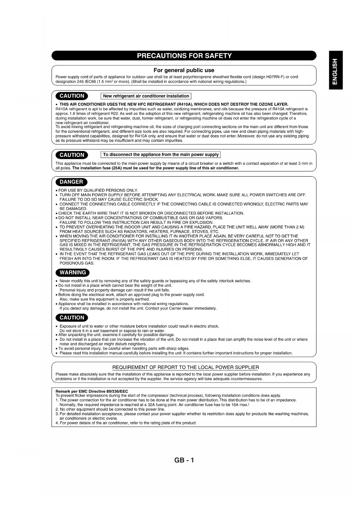
GB Split system "Hi-Wall" indoor unit
ITALIANO
PRECAUTIONS FOR SAFETY 1
Installation Place 2
Refrigerant Piping Connection 3
Evacuating 3
Wiring Connection 4
OTHERS
Gas Leak Test 4
INDICE
PRECAUZIONI PER LA SICUREZZA 1
NP_ΦYΛEiεAΣΦΑΛEIAΣ 1
EynéI_EyKaTaOToaOns. 2
EuvseonPsiukikwvIomegaVWosv 3
Ekkévωση 3
Euvseon Kaawsiomega 4
A_INA
ELevXoc Aiapp_nC Aepi_U 4
INDICE
PRECAUÇÖES RELATIVAS A SEGURANÇA 1
PRECAUTIONS FOR SAFETY
For general public use
Power supply cord of parts of appliance for outdoor use shall be at least polychloroprene sheathed flexible cord (design H07RN-F) or cord designation 245 IEC66 (1.5 mm² or more). (Shall be installed in accordance with national wiring regulations.)
CAUTION
New refrigerant air conditioner Installation
THIS AIR CONDITIONER USES THE NEW HFC REFRIGERANT (R410A), WHICH DOES NOT DESTROY THE OZONE LAYER.
R410A refrigerant is apt to be affected by impurities such as water, oxidizing membranes, and oils because the pressure of R410A refrigerant is approx. 1.6 times of refrigerant R22. As well as the adoption of this new refrigerant, refrigerating machine oil has also been changed. Therefore, during installation work, be sure that water, dust, former refrigerant, or refrigerating machine oil does not enter the refrigeration cycle of a new-refrigerant air conditioner.
To avoid mixing refrigerant and refrigerating machine oil, the sizes of charging port connecting sections on the main unit are different from those for the conventional refrigerant, and different size tools are also required. For connecting pipes, use new and clean piping materials with high-pressure withstand capabilities, designed for R410A only, and ensure that water or dust does not enter. Moreover, do not use any existing piping as its pressure withstand may be insufficient and may contain impurities.
CAUTION
To disconnect the appliance from the main power supply
This appliance must be connected to the main power supply by means of a circuit breaker or a switch with a contact separation of at least 3mm in all poles. The Installation fuse (25A) must be used for the power supply line of this air conditioner.
DANGER
FOR USE BY QUALIFIED PERSONS ONLY.
- TURNOFF MAIN POWER SUPPLY BEFORE ATTEMPTING ANY ELECTRICAL WORK. MAKE SURE ALL POWER SWITCHES ARE OFF. FAILURE TO DO SO MAY CAUSE ELECTRIC SHOCK.
- CONNECT THE CONNECTING CABLE CORRECTLY. IF THE CONNECTING CABLE IS CONNECTED WRONGLY, ELECTRIC PARTS MAY BE DAMAGED.
- CHECK THE EARTH WIRE THAT IT IS NOT BROKEN OR DISCONNECTED BEFORE INSTALLATION.
DO NOT INSTALL NEAR CONCENTRATIONS OF COMBUSTIBLE GAS OR GAS VAPORS.
FAILURE TO FOLLOW THIS INSTRUCTION CAN RESULT IN FIRE OR EXPLOSION.
TO PREVENT OVERHEATING THE INDOOR UNIT AND CAUSING A FIRE HAZARD, PLACE THE UNIT WELL AWAY (MORE THAN 2 M) FROM HEAT SOURCES SUCH AS RADIATORS, HEATHERS, FURNACE, STOVES, ETC.
- WHEN MOVING THE AIR CONDITIONER FOR INSTALLING IT IN ANOTHER PLACE AGAIN, BE VERY CAREFUL NOT TO GET THE SPECIFIED REFRIGERANT (R410A) WITH ANY OTHER GASEOUS BODY INTO THE REFRIGERATION CYCLE. IF AIR OR ANY OTHER GAS IS MIXED IN THE REFRIGERANT, THE GAS PRESSURE IN THE REFRIGERATION CYCLE BECOMES ABNORMALLY HIGH AND IT RESULTINGLY CAUSES BURST OF THE PIPE AND INJURIES ON PERSONS.
- IN THE EVENT THAT THE REFRIGERANT GAS LEAKS OUT OF THE PIPE DURING THE INSTALLATION WORK, IMMEDIATELY LET FRESH AIR INTO THE ROOM. IF THE REFRIGERANT GAS IS HEATED BY FIRE OR SOMETHING ELSE, IT CAUSES GENERATION OF POISONOUS GAS.
WARNING
- Never modify this unit by removing any of the safety guards or bypassing any of the safety interlock switches.
- Do not install in a place which cannot bear the weight of the unit.
Personal injury and property damage can result if the unit falls - Before doing the electrical work, attach an approved plug to the power supply cord. Also, make sure the equipment is properly earthed.
- Appliance shall be installed in accordance with national wiring regulations.
If you detect any damage, do not install the unit. Contact your Carrier dealer immediately.
CAUTION
- Exposure of unit to water or other moisture before installation could result in electric shock.
Do not store it in a wet basement or expose to rain or water.
After unpacking the unit, examine it carefully for possible damage. - Do not install in a place that can increase the vibration of the unit. Do not install in a place that can amplify the noise level of the unit or where noise and discharged air might disturb neighbors.
- To avoid personal injury, be careful when handling parts with sharp edges.
- Please read this installation manual carefully before installing the unit. It contains further important instructions for proper installation
REQUIREMENT OF REPORT TO THE LOCAL POWER SUPPLIER
Please make absolutely sure that the installation of this appliance is reported to the local power supplier before installation. If you experience any problems or if the installation is not accepted by the supplier, the service agency will take adequate countermeasures.
Remark per EMC Directive 89/336/EEC
To prevent flicker impressions during the start of the compressor (technical process), following installation conditions does apply.
1. The power connection for the air conditioner has to be at the main power distribution. This distribution has to be of an impedance. Normally, the required impedance is reached at a 32A fusing point. Air conditioner fuse has to be 16A max!.
2. No other equipment should be connected to this power line.
3. For detailed installation acceptance, please contact your power supplier whether its restriction does apply for products like washing machines, air conditioners or electric ovens.
4. For power details of the air conditioner, refer to the rating plate of the product.
Optional Installation Parts
| Parts name | Q'ty |
| Refrigerant piping Liquid side : Ø6.35 mm Gas side : Ø9.52 mm (38VYX025-R, 38VYX035-R) | One each |
| Pipe insulating material (polyethylene foam, 6 mm thick) | 1 |
| Putty, PVC tapes | One each |
Fixing bolt arrangement of outdoor unit
- Secure the outdoor unit with fixing bolts and nuts if the unit is likely to be exposed to a strong wind.
- Use 8 mm or 10 mm anchor bolts and nuts.
- If it is necessary to drain the defrost water, attach drain nipple ⑨ and cap water proof ⑩ to the bottom plate of the outdoor unit before installing it.
Remark :
- Detail of accessory and installation parts can see in the accessory sheet.
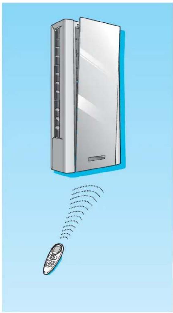
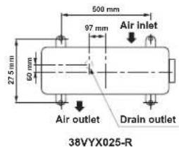
| 38VYX025-R | 38VYX035-R | |
| A | 400 mm | 600 mm |
| B | 45 mm | 100 mm |
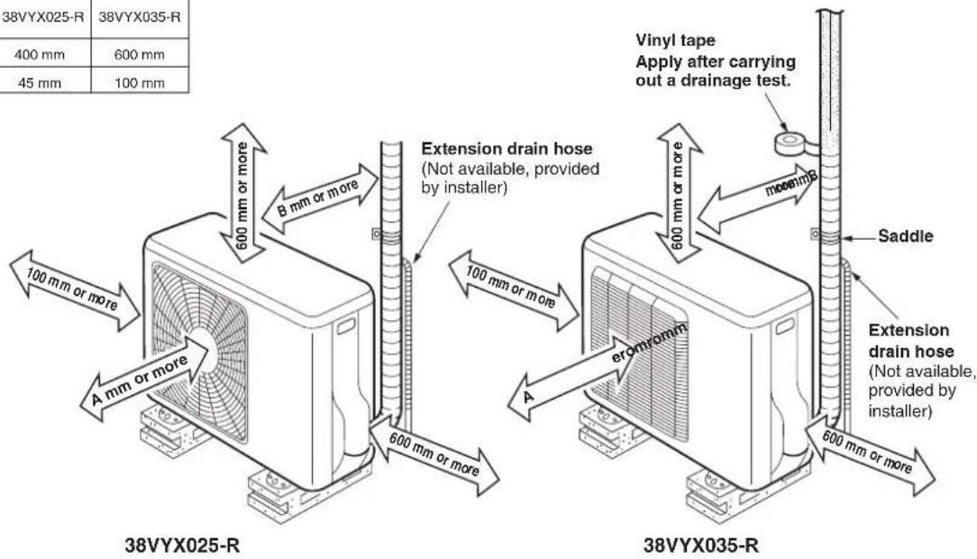
Installation Place
- A place which provides the spaces around the outdoor unit as shown in the diagram
- A place which can bear the weight of the outdoor unit and does not allow an increase in noise level and vibration
- A place where the operation noise and discharged air do not disturb your neighbors
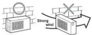
- A place which is not exposed to a strong wind
- A place free of a leakage of combustible gases
- A place which does not block a passage
- When the outdoor unit is to be installed in an elevated position, be sure to secure its feet.
- An allowable length of the connecting pipe is up to 10m for 38VYX025-R and 15m for 38VYX035-R.
An allowable height level is up to 8 m for 38VYX025-R and 10 m for 38VYX035-R - A place where the drain water does not raise any problems
CAUTION
1.Install the outdoor unit without anything blocking the air discharging.
-
When the outdoor unit is installed in a place always exposed to strong wind like a coast or on a high storey of a building, secure the normal fan operation using a duct or a windshield.
-
In particularly windy areas, install the unit such as to avoid admission of wind.
4.Installation in the following places may result in trouble. Do not install the unit in such places.
- A place full of machine oil
A saline-place such as the coast
A place full of sulfide gas - A place where high-frequency waves are likely to be generated as from audio equipment, welders, and medical equipment
Refrigerant Piping Connection Evacuating
Flaring
1.Cut the pipe with a pipe cutter.


2.Insert a flare nut into the pipe and flare the pipe.
- Projection margin in flaring: A (Unit: mm)
Rigid (clutch type)
| Outer dia. of copper pipe | R410A tool used Co | Conventional tool used |
| 6.35 0 to 0.5 | 1.0 to 1.5 | |
| 9.52 0 to 0.5 | 1.0 to 1.5 |
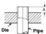
Imperial (wing nut type)
| Outer dia. of copper pipe R410A | |
| 6.35 1.5 to 2.0 | |
| 9.52 1.5 to 2.0 | |
Tightening connection
Align the centers of the connecting pipes and tighten the flare nut as far as possible with your fingers. Then tighten the nut with a spanner and torque wrench as shown in the figure.
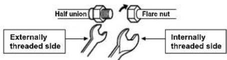
Use a wrench to secure.
Use a torque wrench to tighten.
CAUTION
Do not apply excess torque. Otherwise, the nut may crack depending on the conditions.
(Unit:N·m)
| Outer dia. of copper pipe | Tightening torque |
| Ø6.35 mm | 16 to 18 (1.6 to 1.8 kgf-m) |
| Ø9.52 mm | 30 to 42 (3.0 to 4.2 kgf-m) |
- Tightening torque of flare pipe connections
The operating pressure of R410A is higher than that of R22 (approx. 1.6 times). It is therefore necessary to firmly tighten the flare pipe connecting sections (which connect the indoor and outdoor units) up to the specified tightening torque. Incorrect connections may cause not only a gas leakage, but also damage to the refrigeration cycle.
Shaping pipes
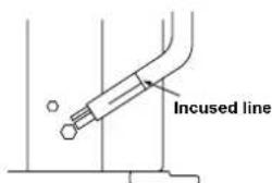
1.How to shape the pipes Shape the pipes along the incused line on the outdoor unit.
2.How to fit position of the pipes Put the edges of the pipes to the place with a distance of 85mm from the incused line.
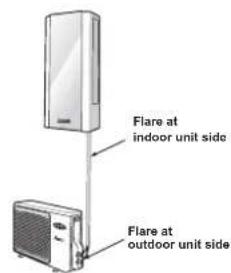
After the piping has been connected to the indoor unit, you can perform the air purge together at once.
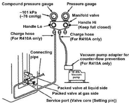
AIR PURGE
Evacuate the air in the connecting pipes and in the indoor unit using a vacuum pump. Do not use the refrigerant in the outdoor unit. For details, see the manual of the vacuum pump.
Using a vacuum pump
Be sure to use a vacuum pump with counter-flow prevention function so that inside oil of the pump does not flow backward into pipes of the air conditioner when the pump stops.
(If oil inside of the vacuum pump enters the air conditioner, which use R410A, refrigeration cycle trouble may result.)
1. Connect the charge hose from the manifold valve to the service port of the packed valve at gas side.
2. Connect the charge hose to the port of the vacuum pump.
3. Open fully the low pressure side handle of the gauge manifold valve.
4. Operate the vacuum pump to start evacuating. Perform evacuating for about 15 minutes if the piping length is 20 meters. (15 minutes for 20 meters) (assuming a pump capacity of 27 liters per minute) Then confirm that the compound pressure gauge reading is -101kPa (-76cmHg)
5.Close the low pressure side valve handle of the gauge manifold valve.
6. Open fully the valve stem of the packed valves (both gas and liquid sides).
7. Remove the charging hose from the service port.
8. Securely tighten the caps on the packed valves.
CAUTION
- KEEP IMPORTANT 4 POINTS FOR PIPING WORK.
(1) Take away dust and moisture (inside of the connecting pipes).
(2) Tighten the connections (between pipes and unit).
(3) Evacuate the air in the connecting pipes using a VACUUM PUMP.
(4) Check gas leak (connected points).
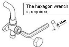
Packed valve handling precautions
- Open the valve stem all the way out, but do not try to open it beyond the stopper.
- Securely tighten the valve stem cap with torque in the following table:
| Gas side 30 to (29.52 mm) (3.0 to 4.2 kgf-m) |
| Liquid side 16 to (26.35 mm) (1.5 to 1.8 kgf-m) |
| Service port |
| 9 to 10 N-m (0.9 to 1.0 kgf-m) |
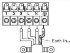
Wiring Connection
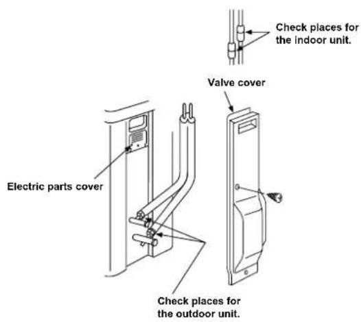
- Remove the valve cover from the outdoor unit.
- Connect the connecting cable to the terminals as identified with their respective matched numbers on the terminal block of indoor and outdoor unit.
- When connecting the connecting cable to the outdoor unit terminals, make a loop as shown in the installation diagram of indoor and outdoor unit to prevent water coming in the outdoor unit.
- Insulate the unused cords (conductors) from any water coming in the outdoor unit. Proceed them so that they do not touch any electrical or metal parts.
Stripping length of the connecting cable
Terminal block
Connecting cable
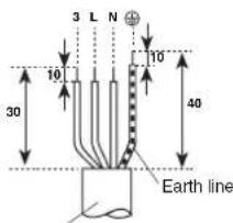
Connecting cable
| Model 38VYX025-R 38VYK035-R | |
| Power source 50/60 Hz, 220 | 240 V Single phase |
| Maximum running current 8A | 11A |
| Plug socket & fuse rating 25A | |
| Power cord H07RN-F or 245 | EC66 (1.5 mm 2or more) |
CAUTION
- Wrong wiring connection may cause some electrical parts burn out.
- Be sure to comply with local cords on running the wire from indoor unit to outdoor unit (size of wire and wiring method, etc.).
- Every wire must be connected firmly.
- This installation fuse (25A) must be used for the power supply line of this air conditioner.
- If incorrect or incomplete wiring is carried out, it will cause an ignition or smoke.
- Prepare the power supply for exclusive use with the air conditioner.
- This product can be connected to the mains. Connection to fixed wiring: A switch which disconnects all poles and has a contact separation of at least 3mm must be incorporated in the fixed wiring.
NOTE: Connecting cable
Wire type:More than H07RN-F or 245 IEC66
OTHERS
Gas Leak Test
- Check the flare nut connections for the gas leak with a gas leak detector or soap water.
PRECAUZIONI PER LA SICUREZZA
NapatnpnbaaTncOdyiae EMC 89/336/EOK
Ia va aotopuyete tpoan taev cokvion tou ouimieo (texvki diabkaia), npente i eapuootov ol akououc auvkenek yekataotaan.
1. H ouvEeTn Tnpoxh Tou Kauatiotikou Th npenti va yivei otov kevtipok niva katavounc. H kupia npox npenti va exei kalann aviptaan.
Fouiooyikn anatouevn avtotaon eituyxavetai ae aopala 32A.H aopala tou kaiataotikou npenei va eivai 16A yioTo.
2. npenei va ouydeetai aan n aeKpiik katavalawon otny iia ypaunioxuc
3. IaeiTojepiec Oxytka e EvkTion nckyataom, Ekoivovnoe nEv npnnaeipoiou yva va uabeE av apapoe 3peipoiou o npovta onwe ta Nauvmpia, ka Kuatiatika kai o nekptikoi pouvoi.
4. Ia nnpopopiec oxetikc me tv loxu katavawong tou kaiatotikou deite tv nivakiia xaapakntpiotkov tou npoiovtoc.
NpOaipEtiKa EApTnMaTa EykataoTaon
4 ZHMANTIKA ZHEMEA IOY IPENEI NA THPENE I E T E P A E I E I OAHNOHZE.
Via R. Sanzio, 9-2005 Villasanta (MI) Italy - Tel. 039/3636.1
The manufacturer reserves the right to change any product specifications without notice.
La cura costante per il miglioramento del prodotto cui lo spocare sono preavviso, cambiamenti o modifiche a quanto descritto.
La recherche permanente de perfectionnement du produit peut nécessiter des modifications ou changements, sans préavis.
DE Änderungen im Zuge der technischen Weiterentwicklung vorbehalten.
El fabricante se reserve el derecho de cambioalgnas specifications de los productos sin previo aviso.
Wijzigingen voorbehonden.
GR H Oaepn TpootraEia via Tny kautepeuon Tou TpoiovtocmuTpei va Etnippei, Xwpi TpoeiOtoinon, aalayec n TPOITOTIOINeic o6o TEPiPyapknav.
O fabricanteresha-seodireito dealterquaisquerespecificaçõesdoproduo,semaviso prévio.
Tillverkaren forbehaller sig ratten till andringar utan foregående meddelande.
FIN Valmistaja pidattaa oikeudet mahdollisin muutoksiin ilman erillsta ilmoitusta.
- 42ADF025, 42ADF035 R-410A
- ENGLISH
- ITALIANO
- INDICE
- PRECAUTIONS FOR SAFETY
- For general public use
- CAUTION
- New refrigerant air conditioner Installation
- To disconnect the appliance from the main power supply
- DANGER
- WARNING
- REQUIREMENT OF REPORT TO THE LOCAL POWER SUPPLIER
- Remark per EMC Directive 89/336/EEC
- Optional Installation Parts
- Fixing bolt arrangement of outdoor unit
- Remark :
- Installation Place
- Refrigerant Piping Connection Evacuating
- Flaring
- Tightening connection
- - Tightening torque of flare pipe connections
- Shaping pipes
- AIR PURGE
- Using a vacuum pump
- - KEEP IMPORTANT 4 POINTS FOR PIPING WORK.
- Packed valve handling precautions
- Wiring Connection
- NOTE: Connecting cable
- OTHERS
- PRECAUZIONI PER LA SICUREZZA
- NapatnpnbaaTncOdyiae EMC 89/336/EOK
- NpOaipEtiKa EApTnMaTa EykataoTaon
Brand : CARRIER
Model : 42ADF025
Category : Air Conditioning