Lia 11 - Heating Superior - Free user manual and instructions
Find the device manual for free Lia 11 Superior in PDF.
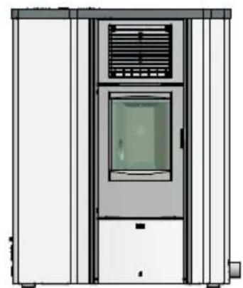
| Product type | Wood stove |
| Brand | Superior |
| Model | Lia 11 |
| Height | 80 cm (estimated) |
| Width | 50 cm (estimated) |
| Depth | 50 cm (estimated) |
| Weight | 120 kg (estimated) |
| Combustion air supply | Combustion air (wood fuel) |
| Nominal power | 10 kW (estimated) |
| Efficiency | 80% (estimated) |
| Main functions | Convection heating; rear or side combustion air connection |
| Cladding material | Ceramic or steel (depending on version) |
| Air connection diameter | 40 mm and 60 mm |
| Primary air throttle system | Yes |
| Maintenance and cleaning | Regular cleaning of the firebox and flue; removal of cladding to access internal components |
| Safety | Ensure the flexible hose does not touch moving parts; possible connection to an external air intake; professional installation recommended |
| Included spare parts | 40 mm and 60 mm connectors, flexible hose, M5 screws, self-tapping screws, clamping collar |
| Repairability | Accessible by removing the cladding; spare parts available on request |
| General information | Manual available in multiple languages; includes detailed installation diagrams |
Frequently Asked Questions - Lia 11 Superior
User questions about Lia 11 Superior
0 question about this device. Answer the ones you know or ask your own.
Ask a new question about this device
Download the instructions for your Heating in PDF format for free! Find your manual Lia 11 - Superior and take your electronic device back in hand. On this page are published all the documents necessary for the use of your device. Lia 11 by Superior.
USER MANUAL Lia 11 Superior
Combustion air connector
No. Description Qty.
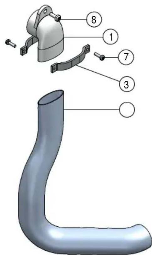
1 Elbow 40 mm 1
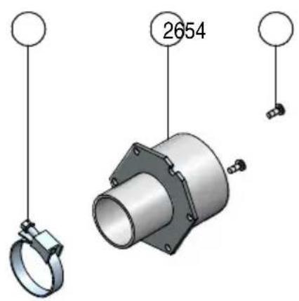
2 Reducing connector 60mm 1
3 Two screw pipe clamp 2
4 Hose 1
5 Hose clip 1
6 Self-tapping screw 2
7 Screw M4 2
8 Screw M5 1
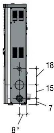
2.0 DIMENSIONS
DT2033750-02

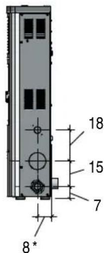
Measurements in cm.
= Dimension includes the rear spacers.
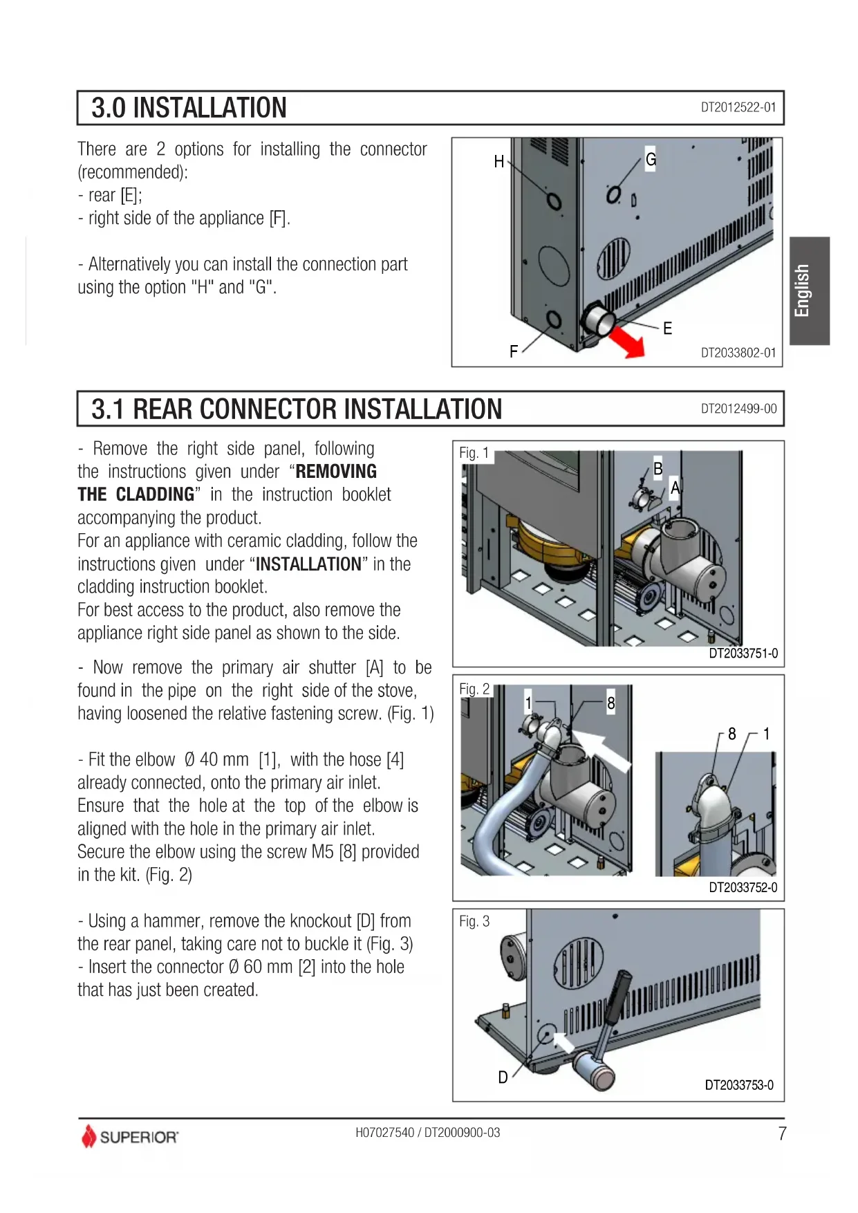
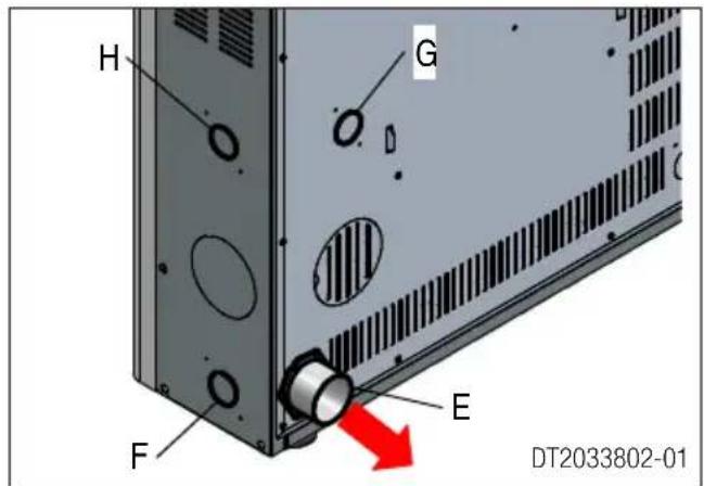
3.0 INSTALLATION
DT2012522-01
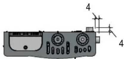
There are 2 options for installing the connector (recommended):
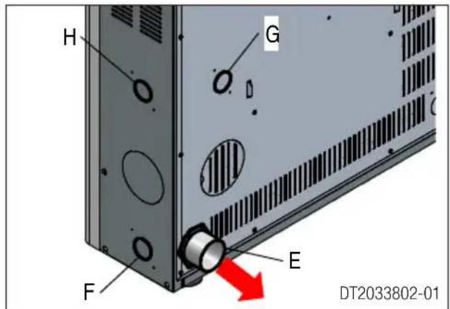
- rear [E];
- right side of the appliance [F].
- Alternatively you can install the connection part using the option "H" and "G".
3.1 REAR CONNECTOR INSTALLATION
DT2012499-00
- Remove the right side panel, following the instructions given under "REMOVING
THE CLADDING" in the instruction booklet accompanying the product.
For an appliance with ceramic cladding, follow the instructions given under "INSTALLATION" in the cladding instruction booklet.
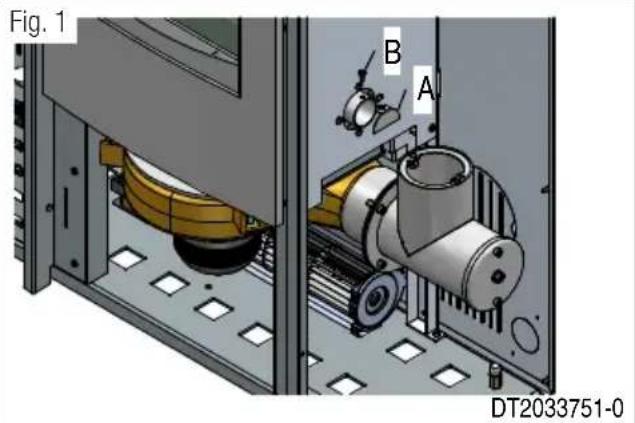
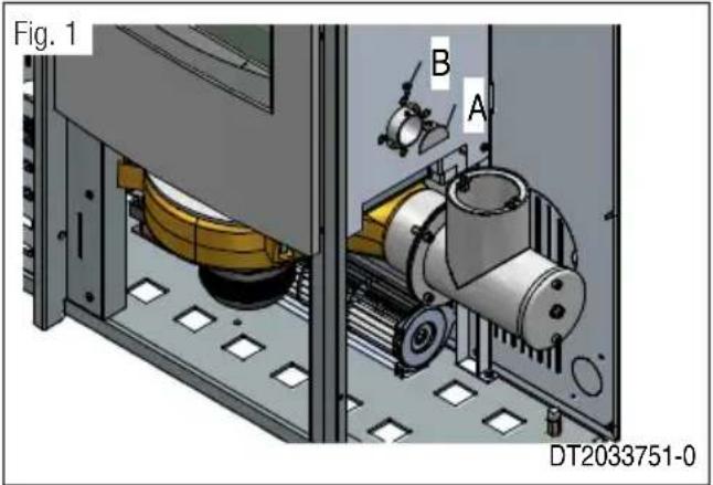
For best access to the product, also remove the appliance right side panel as shown to the side. - Now remove the primary air shutter [A] to be found in the pipe on the right side of the stove, having loosened the relative fastening screw. (Fig. 1)
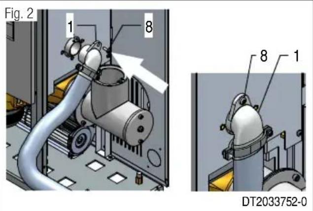
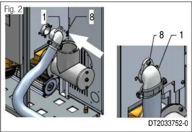
- Fit the elbow 40 mm 1 ,with the hose [4] already connected, onto the primary air inlet.
Ensure that the hole at the top of the elbow is aligned with the hole in the primary air inlet.
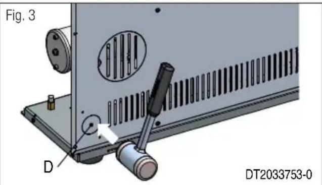
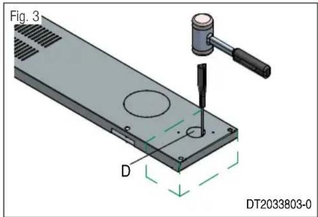
Secure the elbow using the screw M5 [8] provided in the kit. (Fig. 2) - Using a hammer, remove the knockout [D] from the rear panel, taking care not to buckle it (Fig. 3)
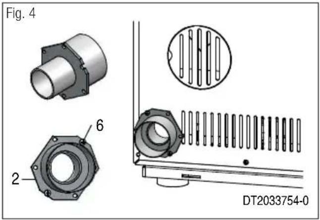
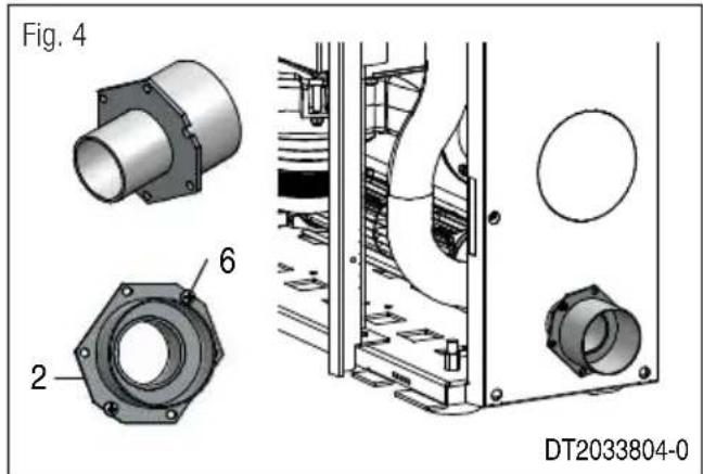
- Insert the connector 60mm [2] into the hole that has just been created.

- Align the slots in the connector [2] with the holes to be found in the rear panel and fasten the connector using the self-tapping screws [6] provided in the kit. (Fig. 4)
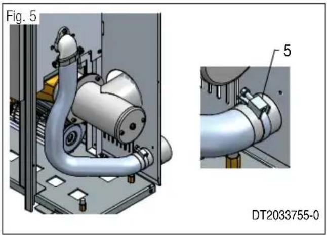
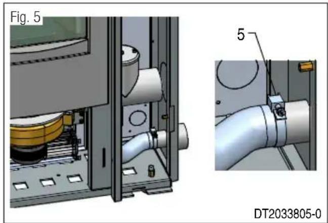
- Using the hose, connect up the connector and the elbow already fastened to the appliance, locking them in place with the hose clip [5] provided in the kit. (Fig. 5)
Check that the hose does not come into contact with parts of the appliance that move during operation.
- Refit the previously removed cladding in the reverse order to removal.
- Connect the appliance to any fresh air intake.
3.2 SIDE CONNECTOR INSTALLATION
DT2012523-00
- Remove the right side panel, following the instructions given under "REMOVING
THE CLADDING" in the instruction booklet accompanying the product.
For an appliance with ceramic cladding, follow the instructions given under "INSTALLATION" in the cladding instruction booklet.
For best access to the product, also remove the appliance right side panel as shown to the side.
- Now remove the primary air shutter [A] to be found in the pipe on the right side of the stove, having loosened the relative fastening screw. (Fig. 1)
- Fit the elbow 40 mm 1 ,with the hose [4]
already connected, onto the primary air inlet.
Ensure that the hole at the top of the elbow is aligned with the hole in the primary air inlet.
Secure the elbow using the screw M5 [8] provided in the kit. (Fig. 2)
- Remove the knockout [D] from the appliance side panel, taking care not to buckle or scratch the panel. (Fig. 3)
- Refit the previously removed side panel.
- Align the slots in the connector [2] with the holes to be found in the appliance side panel and fasten the connector using the self-tapping screws [6] provided in the kit. (Fig. 4)
- Using the hose, connect up the connector and the elbow already fastened to the appliance, locking them in place with the hose clip [5] provided in the kit. (Fig. 5)
- Check that the hose does not come into contact with parts of the appliance that move during operation.
- Refit the previously removed cladding in the reverse order to removal.
- Connect the appliance to any fresh air intake.
Nr. Designation Q. te
1 Raccord coude 40 mm 1
2 Raccord 60 mm 1
3Demi-collier de serrage 2
4 Tuyau flexible 1
5 Bride de serrage 1
6 Vis auto-taraudeuse 2
7 Vis M4 2
8 Vis M5 1
2.0 DIMENSIONS
DT2033750-02
Dimensions en cm.
Alternatively you could use the following technique to connect a connection on the left.
3.1 INSTALLATION DU RACCORD ARRIÈRE
DT2012499-00
Afmetinger in centimeter.
Tel. +39.04235271 - Fax +39.042355178
www.superiorstufe.com
e-mail: info@superiorstufe.com