
PDPS09LR - Pregnant PIONEER - Free user manual and instructions
Find the device manual for free PDPS09LR PIONEER in PDF.
| Product type | Loudspeaker (two-way system) |
| Brand | Pioneer |
| Model | PDPS09LR |
| Intended use | Exclusively with Pioneer plasma display PDP-4330HD or PDP-433HDE |
| Dimensions (W x H x D) | 74 x 630 x 101 mm |
| Weight | 1.6 kg |
| Nominal impedance | 8 Ω |
| Frequency range | 60 Hz - 20,000 Hz |
| Sensitivity | 82 dB/W (at 1 m) |
| Maximum input power | 12 W |
| Rated input power | 4 W |
| Crossover frequency | 3 kHz |
| Woofer | Oval cone type |
| Tweeter | 2.5 cm dome type |
| Enclosure type | Open baffle design |
| Supplied accessories (for 2 speakers) | Speaker cables x2, mounting accessories (upper right, upper left, lower x2), flathead countersunk screws x4, hexagonal head countersunk screws x4, hex key, instruction manual |
| Usage precautions | Do not exceed max power; turn off power before connection; avoid shocks; do not use with a low-power amplifier driven to high volume |
| Cabinet maintenance | Clean with a soft dry cloth; for stubborn dirt, use a cloth dampened with diluted cleaning liquid, then wipe with a dry cloth. Do not use wax, thinner, benzene, or chemicals. |
| CRT display compatibility | Keep away from CRT monitors to avoid interference or color distortion |
| Installation | To be performed by qualified personnel; use the supplied mounting accessories; observe the LEFT/RIGHT sides and UP mark |
| Repairability | Contact a specialist or your dealer; Pioneer disclaims all responsibility for damages resulting from incorrect installation or use |
Frequently Asked Questions - PDPS09LR PIONEER
User questions about PDPS09LR PIONEER
0 question about this device. Answer the ones you know or ask your own.
Ask a new question about this device
Download the instructions for your Pregnant in PDF format for free! Find your manual PDPS09LR - PIONEER and take your electronic device back in hand. On this page are published all the documents necessary for the use of your device. PDPS09LR by PIONEER.
USER MANUAL PDPS09LR PIONEER
Operating Instructions
Mode d'emploi
Bedienungsanleitung
Thank you for buying this Pioneer product.
Please read through these operating instructions before using your speaker system so you will know how to make the most of its performance. After you have finished reading the instructions, put them away in a safe place for future reference.
CAUTION
This product is designed exclusively for use with the PDP-4330HD, PDP-433HDE, PDP-433HDG Pioneer plasma display.
BEFORE USE
●The nominal impedance of this speaker system is 8 ohms.
- In order to prevent damage to the speaker system resulting from input overload, please observe the following precautions:
- Do not supply power to the speaker system in excess of the maximum permissible input. This can result in damage or a possible fire hazard.
- When connecting or disconnecting pin-plugs, be sure that amplifier power is OFF.
- When using a graphic equalizer to emphasize loud sounds of a high frequency range, do not use excessive amplifier volume.
- Do not force a low-powered amplifier to produce a loud volume of sound (the amplifier's harmonic distortion will be increased, and you may damage the speaker).
- Please handle the speakers with sufficient care, as the grille net and the cabinet can become damaged or broken when they are subjected to strong external impacts.
- Placing a CRT computer screen or CRT monitor near to the speakers may result in interference or color distortion. If this happens, distance the monitor from the speakers.
Notes on Installation Work:
This product is marketed assuming that it is installed by qualified personnel with enough skill and competence. Always have an installation specialist or your dealer install and set up the product.
PIONEER cannot assume liabilities for damage caused by mistake in installation or mounting, misuse, modification or a natural disaster.
CHECKING THE ACCESSORIES
■Speaker cable x 2
natural_image
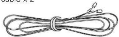
Simple line drawing of a coiled rope or cord with no text or symbols■Speaker mounting fittings
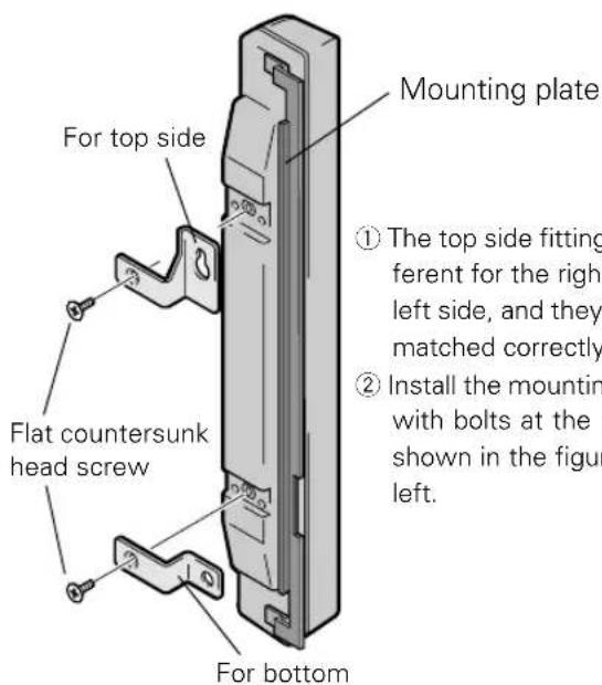
For top right side x 1
For top left side x 1
natural_image
Four identical 3D metal bracket shapes with mounting holes, shown from different angles (no text or symbols)For bottom x 2
■Speaker mounting bolts
Flat countersunk head screw x 4
Hexagon socket head screw x 4


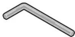
■Mounting tool (Hex wrench)
■Operating Instructions
NOTE:
● Always use the accessory mounting fittings for installation.
- When screws other than those enclosed as accessories are used to install the speakers, the speakers may drop off or accidents may be caused. Always use the screws enclosed as accessories.
INSTALLATION ON THE PLASMA DISPLAY
Perform installation according to the following steps 1 to 2.
1 Attach the mounting fittings to the speakers.
The illustration shows the right speaker.
2 Attach the speakers to the display.
Install the unit marked "RIGHT" on the right side of the display.
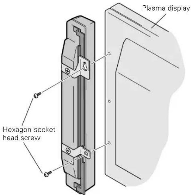
Install the unit marked "LEFT" on the left side of the display.
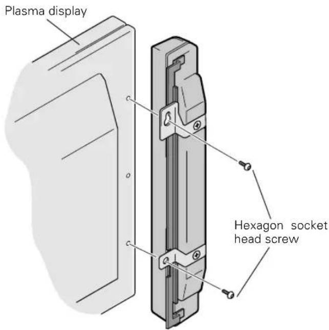
①To attach the speakers to the display, start by placing the upper screw where indicated, tightening until there is a small space of about 5mm between the head of the screw and the display.
②Check the rear of the speakers for the LEFT and RIGHT indicators to make sure you are attaching the correct speaker to the corresponding right or left side. Make sure the UP mark is pointing up, and then attach the speaker by fitting the upper mounting over the head of the screw and sliding down until snug.
③Affix the lower fitting to the display and tighten the screw about halfway.
④ Adjust the position so that the gap between the speaker and the display is uniform, and then tighten the screws firmly.
NOTE:
- When the display is to be moved after speaker installation, do not hold the display by the speakers. Hold the bottom of the display to move it.
- The grille nets are designed to protect the speakers, however excessive force (such as pushing on, or inserting objects between the grille nets) may result in damage.
CONNECTION TO A PLASMA DISPLAY
1 Connecting the speaker cables
①Switch off the power of the plasma display.
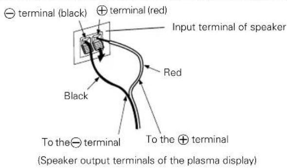
②Connect the input terminals of the speaker system and the speaker output terminals of the plasma display with the accessory speaker cable. Make sure the positive (⊕) and negative (⊖) terminals match when connecting.
- Remove the insulation and twist the core ends together.

- Push the lever, insert the cable into the hole, and release the lever.
- For the input terminals on the plasma display, push the tab to the open position, and insert the wire. Then, close tab firmly to secure the wire in place.
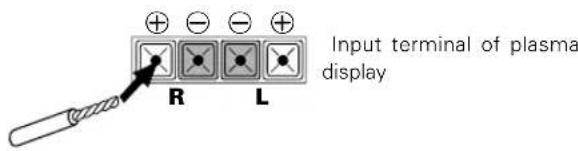
●After connection to the terminals, pull lightly on the cable to confirm that the tips of the cable are properly connected to the terminals. An imperfect connection can cause sound interruptions and noise.
- When cable cores stick out and and lines are short-circuited, an excessive load will be applied to the plasma display and the operation will stop or trouble will be caused.
- When the polarity is reversed for one speaker (left or right) at the time of connection to the plasma display, the bass reproduction will be reduced, the sound positioning will be lost, and a correct stereo effect will not be obtained.
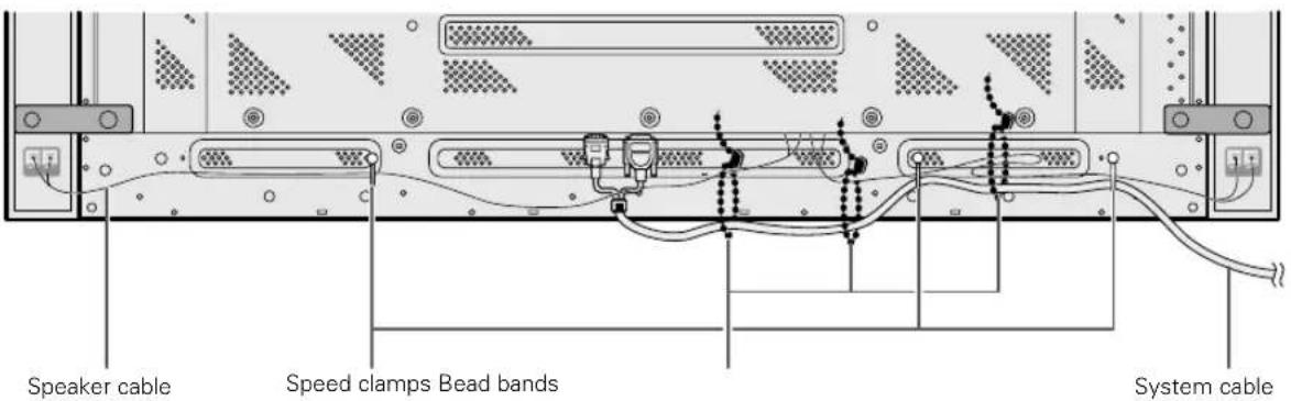
2 How to route cables
Speed clamps and bead bands are included with the plasma display for tidying your cables and keeping extra cable length out of the way.
NOTE:
Cables can be routed to the right or left.
*As viewed from the rear of the display.
To the right
To the left
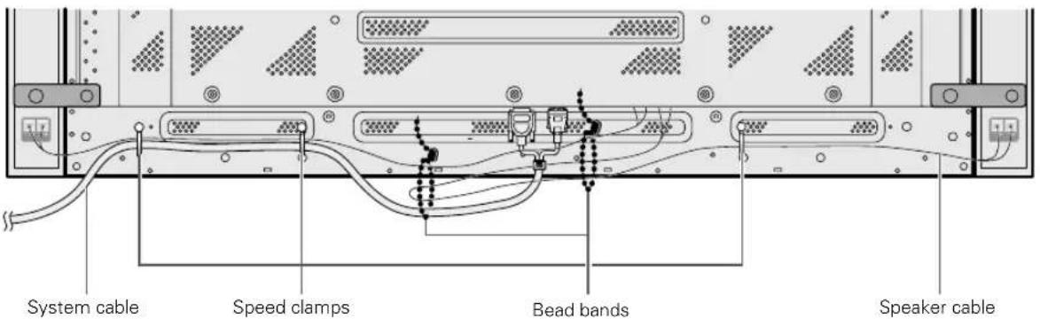
1 Organize cables together using the speed clamps provided with the plasma display.
Insert ① into an appropriate hole on the rear of the unit, then snap ② into the back of ① to fix the clamp.
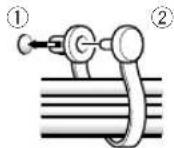
Speed clamps are designed to be difficult to undo once in place. Please attach carefully.
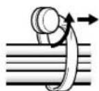
To remove speed clamps
Using pliers, twist the clamp 90° and pull it outward. In some cases the clamp may have deteriorated over time and may be damaged when removed.
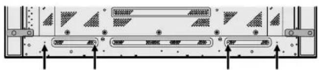
To attach the speed clamps to the main unit
Connect the speed clamps using the 4 holes marked with • below, depending on the situation.
2 Gather separated cables together and secure them with the bead bands provided with the plasma display.

CABINET MAINTENANCE
- Use a polishing cloth or dry cloth to wipe off dust and dirt.
- When the cabinet is very dirty, wipe with a soft cloth moistened with water-diluted cleanser; then wipe again with a dry cloth. Do not use furniture wax or cleaners. They may damage the surface of the cabinet.
●Never use thinner, benzine, insecticide sprays and other chemicals on or near the cabinets, since these will corrode the surfaces. - When a chemical cloth is used, read the cautions for the chemical cloth carefully.
SPECIFICATIONS
Cabinet : Enclosed type
Used speakers (two-way system):
Woofer (for low tones) ...... Oval cone type
Tweeter (for high tones).... 2.5 cm dome type
Nominal impedance 8 Ω
Frequency Range.... 60 to 20,000 Hz
Sensitivity 82 dB/W (at 1 m distance)
Permissible input :
Max. input 12 W
Rated input 4 W
Crossover frequency 3 kHz
External Dimensions ..... 74 (W) x 630 (H) x 101 (D) mm
Weight 1.6 kg
Accessory parts (for 2 speakers)
Speaker cable x 2
...... Speaker mounting fittings (for top left side) x 1
...... Speaker mounting fittings (for top right side) x 1
Speaker mounting fittings (for bottom) x 2
Flat countersunk head screw x 4
Hexagon socket head screw x 4
Mounting tool (Hex wrench) x 1
Operating Instructions x 1
NOTE:
Specifications and design subject to possible modification without notice, due to improvements.
Published by Pioneer Corporation.
Copyright © 2001 Pioneer Corporation.
All rights reserved.
natural_image
Simple line drawing of a coiled rope or cable with no text or symbolsnatural_image
Two identical L-shaped metal bracket diagrams with mounting holes, labeled '1' and 'sup', no text or symbols present.Pour le bas x 2
INSTALLATION SUR ÉCRAN DE VISUALISATION AU PLASMA
Publication de Pioneer Corporation.
© 2001 Pioneer Corporation.
natural_image
Illustration of a coiled cable or wire with connectors (no text or symbols)natural_image
Technical drawing of two L-shaped metal bracket components with holes and mounting holes (no text or symbols)INSTALLATION DES PLASMA DISPLAYS
natural_image
Illustration of a coiled rope or cable with tied ends and connectors (no text or symbols)natural_image
Technical line drawing of two L-shaped metal bracket components with mounting holes (no text or symbols)Copyright © 2001 Pioneer Corporation.
natural_image
Simple line drawing of a coiled cable or rope with no text or symbolsBEVESTIGING TEGEN HET PLASMABEELDSCHERM
Copyright © 2001 Pioneer Corporation.
natural_image
Simple line drawing of a bundle of rope or cord (no text or symbols)natural_image
Two identical metal bracket diagrams with holes, labeled 'derecho' and 'Para' (no text or symbols on the brackets themselves)Para la parte inferior x 2
Copyright © 2001 Pioneer Corporation.
Selecting fine audio equipment such as the unit you've just purchased is only the start of your musical enjoyment. Now it's time to consider how you can maximize the fun and excitement your equipment offers. This manufacturer and the Electronic Industries Association's Consumer Electronics Group want you to get the most out of your equipment by playing it at a safe level. One that lets the sound come through loud and clear without annoying blaring or distortion-and, most importantly, without affecting your sensitive hearing.
Sound can be deceiving. Over time your hearing “comfort level” adapts to higher volumes of sound. So what sounds “normal” can actually be loud and harmful to your hearing. Guard against this by setting your equipment at a safe level BEFORE your hearing adapts.
To establish a safe level:
- Start your volume control at a low setting.
- Slowly increase the sound until you can hear it comfortably and clearly, and without distortion.
Once you have established a comfortable sound level:
- Set the dial and leave it there.
Taking a minute to do this now will help to prevent hearing damage or loss in the future. After all, we want you listening for a lifetime.
We Want You Listening For A Lifetime
Used wisely, your new sound equipment will provide a lifetime of fun and enjoyment. Since hearing damage from loud noise is often undetectable until it is too late, this manufacturer and the Electronic Industries Association's Consumer Electronics Group recommend you avoid prolonged exposure to excessive noise. This list of sound levels is included for your protection.
Decibel
Level Example
30 Quiet library, soft whispers
40 Living room, refrigerator, bedroom away from traffic
50 Light traffic, normal conversation, quiet office
60 Air conditioner at 20 feet, sewing machine
70 Vacuum cleaner, hair dryer, noisy restaurant
80 Average city traffic, garbage disposals, alarm clock at two feet.
THE FOLLOWING NOISES CAN BE DANGEROUS UNDER CONSTANT EXPOSURE
90 Subway, motorcycle, truck traffic, lawn mower
100 Garbage truck, chain saw, pneumatic drill
120 Rock band concert in front of speakers, thunderclap
140 Gunshot blast, jet plane
180 Rocket launching pad
Information courtesy of the Deafness Research Foundation.


S001 En
AFTER-SALES SERVICE FOR PIONEER PRODUCTS
Please contact the dealer or distributor from where you purchased the product for its after-sales service (including warranty conditions) or any other information. In case the necessary information is not available, please contact the Pioneer's subsidiaries (regional service headquarters) listed below:
PLEASE DO NOT SHIP YOUR PRODUCT TO THE COMPANIES at the addresses listed below for repair without advance contact, for these companies are not repair locations.
AMERICA
PIONEER ELECTRONICS (USA) INC.
CUSTOMER SUPPORT DIVISION
P.O.BOX1760, LONG BEACH, CA90801-1760, U.S.A.
EUROPE
PIONEER EUROPE NV
EUROPEAN SERVICE DIVISION
HAVEN 1087, KEETBERGLAAN 1, B-9120 MELSELE, BELGIUM
ASEAN
PIONEER ELECTRONICS ASIACENTRE PTE. LTD.
SERVICE DEPARTMENT
253, ALEXANDRA ROAD #04-01 SINGAPORE 159936
JAPAN AND OTHERS
PIONEER CORPORATION (HEAD OFFICE)
CUSTOMER SUPPORT CENTER
Published by Pioneer Corporation.
Copyright © 2001 Pioneer Corporation.
All rights reserved.

- CAUTION
- BEFORE USE
- Notes on Installation Work:
- CHECKING THE ACCESSORIES
- NOTE:
- INSTALLATION ON THE PLASMA DISPLAY
- Attach the mounting fittings to the speakers.
- Attach the speakers to the display.
- CONNECTION TO A PLASMA DISPLAY
- Connecting the speaker cables
- How to route cables
- To the right
- To the left
- Organize cables together using the speed clamps provided with the plasma display.
- To remove speed clamps
- To attach the speed clamps to the main unit
- Gather separated cables together and secure them with the bead bands provided with the plasma display.
- CABINET MAINTENANCE
- SPECIFICATIONS
- INSTALLATION SUR ÉCRAN DE VISUALISATION AU PLASMA
- INSTALLATION DES PLASMA DISPLAYS
- BEVESTIGING TEGEN HET PLASMABEELDSCHERM
- To establish a safe level:
- Once you have established a comfortable sound level:
- We Want You Listening For A Lifetime
- Decibel
- Level Example
- THE FOLLOWING NOISES CAN BE DANGEROUS UNDER CONSTANT EXPOSURE
- AFTER-SALES SERVICE FOR PIONEER PRODUCTS
- AMERICA
- EUROPE
- ASEAN
- JAPAN AND OTHERS
Brand : PIONEER
Model : PDPS09LR
Category : Pregnant