SMART SX MLINK Set - Remote control MULTIPLEX - Free user manual and instructions
Find the device manual for free SMART SX MLINK Set MULTIPLEX in PDF.

User questions about SMART SX MLINK Set MULTIPLEX
0 question about this device. Answer the ones you know or ask your own.
Ask a new question about this device
Download the instructions for your Remote control in PDF format for free! Find your manual SMART SX MLINK Set - MULTIPLEX and take your electronic device back in hand. On this page are published all the documents necessary for the use of your device. SMART SX MLINK Set by MULTIPLEX.
USER MANUAL SMART SX MLINK Set MULTIPLEX
natural_image
Interior view of a battery pack with three cylindrical batteries (no visible text or symbols)- Binding
Concept for the future!
natural_image
Illustration of a light bulb with the letters 'ID' and a starburst background (no text or symbols)text_image
100% 90% 70%radar
| Segment | Value (%) | |---|---| | Top Left | 100 | | Top Right | 70 | | Bottom Left | 5 | | Bottom Right | 100 |natural_image
Black KOCUBUCH drone controller with battery, battery pack, and power supply components (no text or symbols on main body)natural_image
White model airplane with attached control panels and battery pack (no visible text or symbols)natural_image
Interior view of a battery pack with three cylindrical batteries, no visible text or symbols on the main body.natural_image
Illustration of a light bulb with the letters 'ID' and a starburst background (no text or symbols on the bulb itself)natural_image
Line drawing of a propeller airplane viewed from above (no text or symbols)natural_image
White model airplane with visible tail and wing edges, no text or symbols presentModell Easy Star II
natural_image
Black and white illustration of a stylized aircraft with visible wings and tail (no text or symbols)Modell FunCopter
natural_image
Black multi-plex speed controller with labeled 'SMARTEX' branding (no additional text or symbols visible)natural_image
Symbol of a waste bin with no text or labels3.2 Features of the SMART SX 17
-
Safety notes, other information 18
-
Set contents / Accessories 20
-
Specification
6.1 SMART SX transmitter 20
6.2 RX-5 light M-LINK receiver 21
- Handling
7.1 Transmitter controls 21
7.2 Receiver controls 21
7.3 Transmitter aerial 21
7.4 Inserting dry / rechargeable cells 22
7.5 Voltage monitor / operating times 22
7.6 Binding 22
7.7 Channel assignment 22
7.8 Mode switching 23
7.9 Servo reverse 23
7.10 Trims 23
7.11 Dual Rates 23
7.12 Fail-Safe 24
7.13 Auxiliary (AUX) channel 24
7.14 Range checking 24
7.15 Model memory (ID) 24
7.16 Installing the receiver in the model 25
7.17 The SMART SX as Pupil transmitter 25
7.18 Firmware update / settings for future RR+ models 26
7.19 Installing aluminium sticks 26
7.20 Speech output of telemetry data 26
-
Advice and Service 26
-
Care and Maintenance 27
-
CE Conformity Declarations 27
-
Guarantee / Liability Exclusion 27
-
Disposal 27
-
Fault-finding 28
Congratulations on purchasing your new radio control system. We are delighted that you have selected the MULTIPLEX SMART SX M-LINK. You are now the owner of a superb system for the newcomer to the hobby of radio-controlled modelling. We hope you have many hours of fun and success with your new equipment.
2. QUICK-START
- Unpatch the transmitter and receiver
Store the documents safely.
16
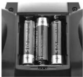
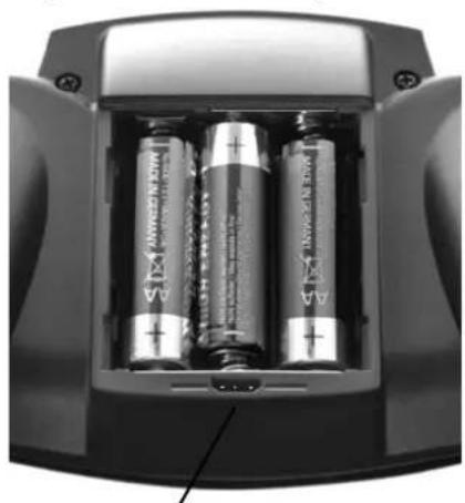
- Insert the batteries
It is essential to maintain correct polarity (see adjacent illustration). Reversed polarity may ruin the transmitter and / or the cells.
natural_image
Interior view of a battery pack with three cylindrical batteries (no visible text or symbols)- Binding
• Preparing the model
When binding is complete, the receiving system immediately starts operating. Secure the model carefully so that no damage can result if the propeller should start turning.
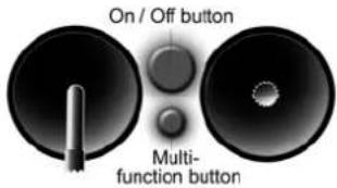
• Prepare the transmitter
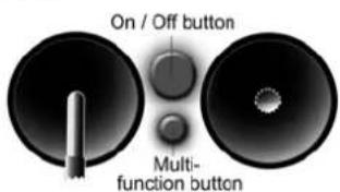
Hold the multi-function button pressed in and switch the transmitter on, then release the button again. The LED flashes at a high rate.
• Prepare the receiver
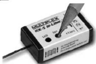
Switch the receiver on with the SET button held pressed in; the receiver LED now flashes at a high rate.
text_image
On / Off button Multi- function button
text_image
MATELEX 6X-S M-LINK 120 4x 75 8x 4.1mmIf binding is successful, both LEDs revert to a slow flashing rate.
- Check the directions of servo rotation
• Model with ID receiver
The transmitter emits an audible signal when it detects the receiver. No further adjustments are required.
- Model with normal M-Link receiver (light or telemetry)
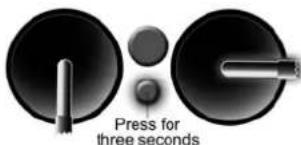
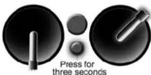
All the control surfaces (servos) must respond to the sticks in the correct direction; check and reverse the servos if necessary: move the correct stick to one end-point and hold the multi-function
button pressed in for three seconds: the servo now reverses, and moves to the opposite end-point.
text_image
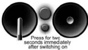
Press for three seconds- Carry out a range check
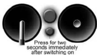
It is important to check radio range before the first flight: hold the multi-function button pressed in for two
seconds immediately after switching on, and the LED glows constantly. The transmitter now generates greatly reduced power, and emits an audible warning signal. In this mode the
text_image
Press for two seconds immediately after switching oncontrol system must continue to function up to a distance of about fifty metres.
6. Flying the model
These few steps are all you need to do before the first flight. Be sure to keep to the correct sequence of switching on and off: always switch the transmitter on first, and only then the receiving system; reverse the sequence when switching off. Before you launch and fly your model please read through the manufacturer's notes; those concerning safety and other warnings are particularly important.
3. INTRODUCTION
These operating instructions are an integral part of the product, and contain important information and safety notes. Please store them in a safe place, and be sure to pass them on to the new owner if you ever dispose of the equipment.
3.1 The SMART SX philosophy
The SMART SX M-LINK is a compact, intelligent six-channel beginners' radio control system with a
concept for the future!
The SMART SX intelligent beginners' radio control system is fully compatible with other MULTIPLEX systems, from the telemetry-capable COCKPIT SX right up to the high-end PROFI TX system. The same applies to the small ID receiver supplied in the set, which even works with the sophisticated PROFI TX transmitter.
However, MULTIPLEX offers much more than this: our range also includes a carefully considered, consistent series of models. Our complete RTF (Ready-to-Fly) packages contain the model, factory-assembled and almost ready for the air, the SMART SX transmitter, an RX-5 M-LINK ID receiver, dry cells, a rechargeable flight battery and a 230 V battery charger. Once you have unpacked the model, all you have to do is attach the wings, charge the flight pack and receiver battery (if used), and prepare the transmitter. When these few procedures are out of the way, there is nothing to stop you flying the model.
The presence of the M-LINK ID receiver enables the SMART SX to detect the specific model, and automatically activate the associated settings from its enormous reserve of model memories: fifty independent model memories are available. All compatible MULTIPLEX ELAPOR® models from RR+ to RTF are programmed in the transmitter as standard. Many models from other manufacturers can be fitted with an ID receiver,

natural_image
Illustration of a light bulb with a 'ID' on its body, surrounded by radiating lines (no text or symbols)and this makes it very simple for the intelligent SMART SX transmitter to detect each ID receiver, and exploit its advantages. The overall concept of transmitter and model expands with the demands of the model pilot. MULTIPLEX offers a complete and consistent system whose components are all compatible.
Once you have gained initial experience with an RTF model, and wish to own and fly another aircraft, we recommend that you move on to a MULTIPLEX RR+ model. Our RR+ packages are just as complete as the RTF models, with the exception of the SMART SX M-LINK transmitter and battery charger, as you already own these two components from your first RTF model. You can use them again, since the transmitter and charger are fully compatible with the RR+ models. The transmitter detects all compatible RR+ models which are currently available. When new models come onto the market, you can load their settings into your transmitter using the free MULTIPLEX Launcher software; this saves you the task of making the adjustments yourself.
When your requirements have expanded to the point where you are keen to invest even more time in the hobby of model flying, you can easily upgrade to an even more powerful MULTIPLEX transmitter, e.g. a COCKPIT SX system, since all the receivers are compatible. This represents long-term system compatibility, and saves you money.
3.2 Features of the SMART SX
The SMART SX M-LINK is a compact, intelligent six-channel beginners' radio control system which includes groundbreaking features, some of them patented.
- The transmitter exploits its intelligent patented model identification system to assign a specific model (i.e. its receiver) to a pre-programmed model memory. All MULTIPLEX RR+ and RTF models are already programmed in separate model memories.
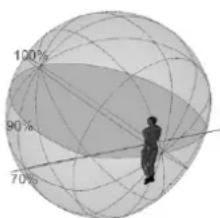
- The transmitter is fitted with an aerial incorporating the newly patented IOAT technology. The optimised directional characteristics significantly enhance
text_image
100% 90% 70%IOAT radiation pattern
radar
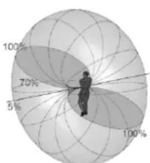
| Angle | Value (%) | |---|---| | 0 | 5 | | 30 | 70 | | 60 | 100 | | 90 | 5 | | 120 | 5 |Radiation pattern of a conventional 2,4 GHz aerial
security, and take effective range far beyond the limits of vision. The 2.4 GHz aerial integrated into the transmitter case is always directed at the optimum angle, and the radiated signal to the rear is minimal; all the radiated power is effectively concentrated in the flying sector.
- The small, light transmitter is very easy to handle, and can be used for many types of model. Its ergonomically efficient case is very comfortable to hold.
- Five fully proportional channels are available: elevator, rudder and throttle plus two aileron channels. A switched channel can also be used, controlled by the throttle function trim lever.
- All the primary control surface functions feature digital trims.
- A buzzer is used to provide audible feedback to the user, indicating the most important processes, such as: detecting the ID receiver, range-check, voltage monitor, trim function, Dual Rate setting, model select.
- The transmitter software is carefully structured with ultra-simple operation in mind. The simplicity of operating the transmitter makes it extremely easy to set it up to suit virtually any other model from a huge range of manufacturers. The transmitter even stores the final trim settings for each specific model.
- The pioneering, ultra-secure M-LINK transmission process with its intelligent channel management system creates the best possible pre-conditions for totally reliable operation. The M-LINK process makes it possible to operate up to 150 models simultaneously without mutual interference.
- With the three recommended AA-size dry cells the SMART SX transmitter operates for the enormously long time of up to 25 hours. The unit also includes an integral voltage monitor with a warning threshold set at a sensible level.
- It is possible to set up the transmitter to control almost any RC model currently available.
- The SMART SX transmitter is ideal for use as a Pupil transmitter in a Trainer system, providing the beginner with the perfect opportunity to learn the initial steps in the art of model flying quickly and safely. The wireless connection to the Teacher transmitter requires the M-LINK Trainer Stick - which can be used with any Trainer-capable MPX transmitter fitted with a multifunction socket - or a PROFITx using COPILOT.
- The transmitter software (= firmware) can be updated using the integral interface located in the battery compartment. This makes it possible to keep the transmitter completely up-to-date at all times. The same method can be used to transfer the settings for new RR+ models into the transmitter.
4. SAFETY NOTES, OTHER INFORMATION
Radio-controlled models and the associated RC systems are not playthings in the usual sense of the term. Building and operating them safely calls for a certain level of technical competence and manual skill, together with discipline and a responsible attitude at the flying field. Errors and negligence in building and flying the model can result in serious personal injury and damage to property. Since neither we, as manufacturer, nor the retailer have any control over the con-
struction, maintenance and operation of our products, we are obliged to take this opportunity to point out these hazards and to emphasise your personal responsibility. We deny all liability.
It really is essential to observe the following safety notes, as you bear the responsibility for the safe operation of this product:
- Please read right through these instructions, and do not operate the system until you have studied the information and the following safety notes.
- It is never permissible to make technical modifications to the radio control system. Use genuine accessories and replacement parts exclusively; these include transmitter battery, receiver and servos.
- If you intend to operate the system in conjunction with products from other manufacturers, you must ensure that they are of good quality and work properly. Every new or changed combination of components must be checked exhaustively before use; the equipment must work correctly and at full range. Do not operate the RC system or the model if something is not in order. First seek out and eliminate the problem.
- A model flying out of control for whatever reason can certainly cause serious personal injury and property damage. For this reason it is the modeller's responsibility to take out third-party insurance for model aircraft, and heed the regulations. This really is mandatory.
- Always keep to the correct sequence when switching the system on and off, as this avoids the risk of the motor bursting into life unexpectedly:
- When switching on
Always switch the transmitter on before connecting the flight battery or switching the receiving system on. - When switching off
Always disconnect the flight battery or switch the receiving system off before switching the transmitter off. - Have your RC system - especially the transmitter and receiver - checked at regular intervals (every two or three years) by an authorised MULTIPLEX Service Centre.
- The transmitter must be operated exclusively within the stated temperature range. Please note that condensation may occur inside the transmitter if it is subjected to a major change in temperature. Damp can affect the operation of the transmitter and any other electronic equipment.
- If moisture affects any electrical unit, cease operations immediately, disconnect the power supply, and allow the device to dry out completely, preferably with the case open; this may take several days. After this carry out a careful check of its functions. If you are still unsure, take the affected equipment to an authorised MULTIPLEX Service Centre for checking.
In addition to these safety notes, please observe the following points.
- Build your model with great care; this applies in particular if you have to repair your model. The responsibility for completing the work competently rests with you.
- Install the servos and mechanical linkages in such a way that the control surfaces deflect freely, and are not mechanically obstructed (stalled) at either end-point (maximum travel).
- Adjust the horns, output arms and linkages as accurately as possible, taking care to keep lost motion (slop) to an absolute minimum. This avoids overloading the servos, which are then able to exploit their full potential performance. These measures ensure that the servos have a long useful life, providing the highest possible margin of safety.
- Provide effective protection for the receiver, the batteries, the servos and the other RC components, and observe the notes in the operating instructions supplied with them. An important factor in this is the correct balancing of propellers and rotors. Any part of a power system which is damaged or runs out of true must be replaced at once.
- Do not place cables under strain, do not kink them, and do protect them from rotating parts.
- Avoid unnecessarily long or superfluous servo extension leads, and always use cable of adequate conductor cross-section (voltage loss). We recommend at least 0.24 mm ^2 as a starting point.
- Take appropriate measures to avoid interference due to static charge, powerful electrical or electromagnetic fields (this includes the suppression of electric motors with suitable capacitors), and keep such sources well away from the RC system, the receiver aerial, wiring and batteries.
- Maintain adequate spacing between cables which carry high currents (e.g. electric power system leads) and the RC system. In particular the cables between brushless electric motors and their speed controllers must be kept short (max. 10 to 15 cm if possible).
- Check all functions carefully, and ensure that you are properly familiar with the method of operating your transmitter before using it to control a model.
You should also examine your model at regular intervals, checking the following points in particular:
- Check that control surfaces and linkages are free-moving and devoid of lost motion (slop);
- Check that pushrods, other linkage components, hinges, etc. are strong enough and in perfect condition:
- Look for fractures, cracks and distortions in the model, the RC components and the power system:
- All cables and connectors must be in good condition and make reliable contact;
- Check the condition of the power supply system and wiring, including the switch harness, and the
external condition of the battery cells. This also includes the use of appropriate charging procedures to match the battery type, and regular main-tenance of the batteries themselves.
Pay particular attention to the system's power supplies: both in the transmitter and in the model.
- Remove the dry cells from the transmitter if you know you will not be using it for a long period, as they could leak and cause damage.
• Always fit new dry cells after a protracted period of non-use. - If you hear the voltage monitor warning sound, land your model (or otherwise cease operations) immediately. Change the dry cells for new ones of the correct type.
- Never attempt to recharge dry cells, as they could explode.
- At regular intervals check the state of the receiver battery or batteries, and the BEC system.
- Rechargeable batteries must be charged regularly; never wait until the servos' movements are perceptibly slower. Make it a rule to charge your batteries before every flying session.
- If you are using rechargeable cells, it is essential to observe the charging instructions provided by their manufacturer.
Before every flight carry out the following procedures and checks:
- Carefully charge up the transmitter, receiver and flight batteries, and check their state of charge regularly during the session and between flights.
- When you arrive at the launch point, register with the site warden or flight director, and do not switch ON until you have checked with the other pilots present that your channel is free.
- Check that all control functions and auxiliary functions are working correctly and in the correct "sense" (direction).
If you discover a problem, do not launch the model. First seek the fault, eliminate it, and check again.
When operating your model you should always observe the following points:
- If you have no experience in flying a model aeroplane, please ask a skilled pilot to help you initially. A Trainer system is a great help during the early stages.
- Only fly your model at a suitable site. Never operate a model in the vicinity of buildings or roads.
- Do not fly or steer your model over or towards spectators. Never place people or animals in danger.
- Do not carry out any high-risk flying or driving manoeuvres.
- In Germany and in many other countries it is a legal requirement to take out third-party insurance cover for the operation of model aircraft. Find out the exact legal requirements for your region, and observe them strictly.
-
Be realistic when assessing your own skills and capabilities: don't over-estimate what you can do.
-
If you notice any sign of a problem or interference, land your model immediately, or cease operations.
• Static charge hazard!
In extremely dry air (in mountainous terrain and on steep slopes close to weather fronts) static charges may develop in the transmitter and / or the pilot. Such a charge may be dissipated by a static spark which could damage the transmitter or cause interference, and might even endanger the pilot. The same effects may occur when an electrical storm is building up.
• Counter-measures:
Cease operations as quickly as possible, walk a little way down the mountain in order to reach a less exposed point, and never fly in a thunderstorm or in the vicinity of such conditions.
- Keep well clear of mobile telephones!
As a basic rule we recommend that you switch off mobile telephones and any other device which could affect the pilot's concentration.
- The SMART SX is protected against interference from electro-magnetic fields, such as those generated by mobile telephones. The system far exceeds the legal requirements regarding interference rejection. However, the rapid development in mobile radio, and the enormous range of devices now in use, do represent a residual risk which is difficult to assess. For safety's sake we therefore recommend that you always keep at least two metres away from any mobile telephone which is switched on.
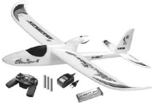
5. SET CONTENTS / ACCESSORIES
The SMART SX radio control set contains the components shown in the photo below:

natural_image
Black KNOBEN23 electric drone with battery, power cord, and lightbulb icon (no text or symbols on device)• SMART SX M-LINK transmitter
• RX-5 light M-LINK ID 1 receiver
• Three AA-size dry cells
• Multi-lingual instructions
A set of optional aluminium stick tops can be fitted to the transmitter (see Chapter 7.19). It Aluknüppel are in black (# 7 3305) and orange (# 7 3306) available.
natural_image
White model airplane with propeller wings and control components (no visible text or symbols)If you have acquired the transmitter together with a MULTIPLEX RTF model aircraft, the set contents also include the aeroplane, a matching flight battery and a 230 V battery charger, as shown in the second photo.
The transmitter is available in two different stick modes (see Chapter 7.8):
• SMART SM M-LINK Mode 1 + 3 (# 1 5300)
• SMART SM M-LINK Mode 2 + 4 (# 1 5301)
The following additional items are available:
- RX-5 light M-LINK receiver If, for example, you wish to build and equip a MULTI- PLEX RR model, a normal kit or another model, you
will need an additional M-LINK receiver. In this case please note the ID number required to match the model concerned (see Chapter 7.15).
text_image
MOLY-EBX RLS R-LINK ID 1 123 A17003 ISO 1.045- USB PC lead (# 85149)
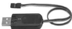
You will need a USB adapter with Uni connector to load a firmware update via the port in the battery compartment, or to transfer
new RR+ model settings into the transmitter (see Chapter 7.18).
6. SPECIFICATION
6.1 SMART SX transmitter
Frequency band: 2.4 GHz
Transmission type: FHSS M-LINK
Aerial: Integral IOAT aerial
Servo channels: 6
Model memories: 50
Servo signal format: 1.5 +/- 0.55 ms (at 100% travel)
Power supply: 3 AA-size cells
Current drain: approx. 85 mA
Weight: approx. 355 g (incl. batteries)
Dimensions (L x W x H): approx. 193 x 148 x 53 mm
6.2 RX-5 light M-LINK receiver
Servo channels: 5
Connector system: UNI
Receive system: 2.4 GHz FHSS
Operating voltage: 3.5 V ... 9.0 V
Power supply: 4 - 6 NiXX cells, 2S LiXX
Permissible operating
temperature range: -20 ^ C ... +55 ^ C
Weight: approx. 7 g
Dimensions (L x W x H): approx. 34 x 19.5 x 11 mm
7. HANDLING
7.1 Transmitter controls
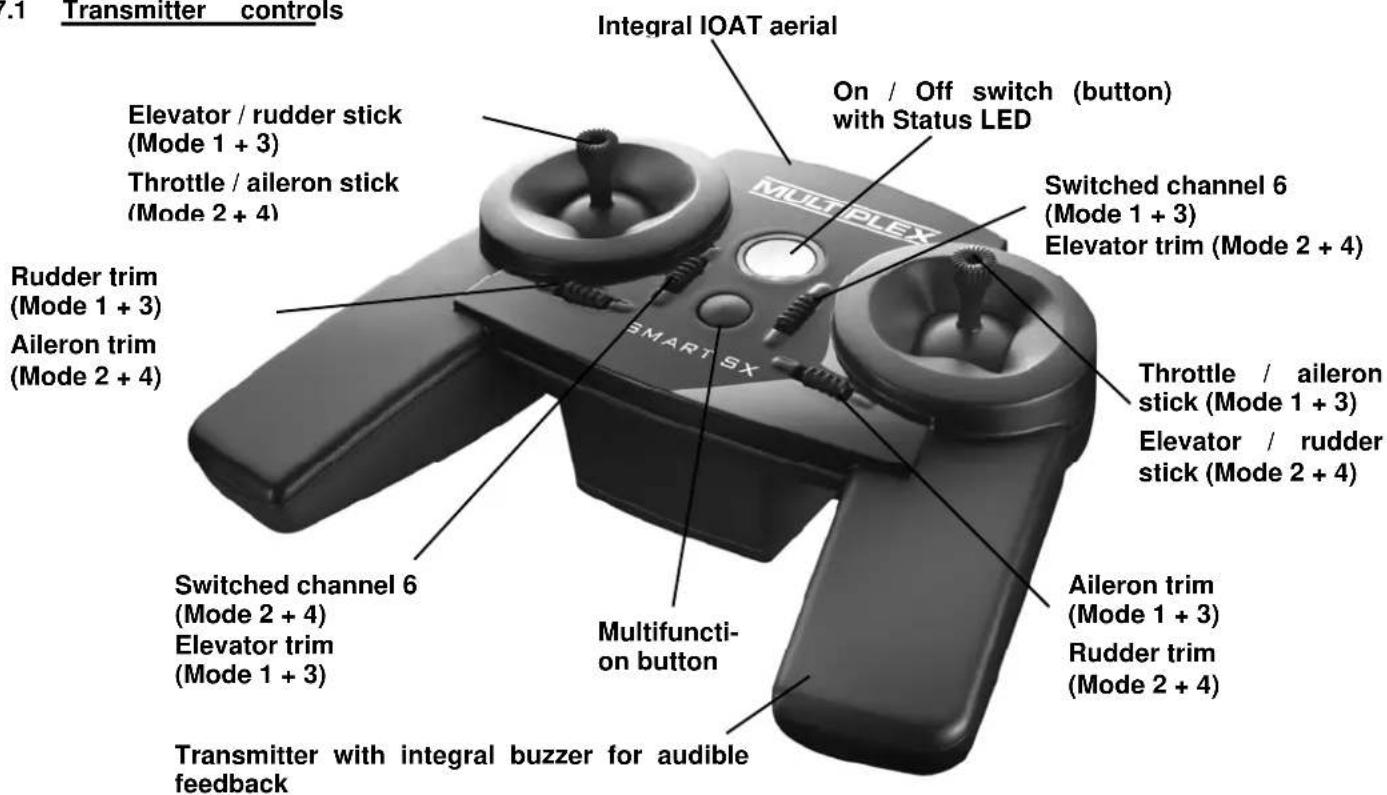
text_image
Transmitter controls Elevator / rudder stick (Mode 1 + 3) Throttle / aileron stick (Mode 2 + 4) Rudder trim (Mode 1 + 3) Aileron trim (Mode 2 + 4) Switched channel 6 (Mode 2 + 4) Elevator trim (Mode 1 + 3) Transmitter with integral buzzer for audible feedback Multifunction button Integral IOAT aerial On / Off switch (button) with Status LED Switched channel 6 (Mode 1 + 3) Elevator trim (Mode 2 + 4) Throttle / aileron stick (Mode 1 + 3) Elevator / rudder stick (Mode 2 + 4) Aileron trim (Mode 1 + 3) Rudder trim (Mode 2 + 4)Battery compartment with cells fitted (always maintain correct cell polarity, as shown in this photo)
natural_image
Interior view of a battery pack with three cylindrical batteries, no visible text or symbols on the main body.PC communication port with USB lead (# 85149).
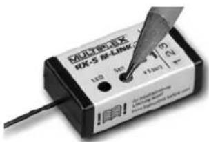
7.2 Receiver controls
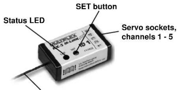
text_image
Status LED SET button Servo sockets, channels 1 - 52.4 GHz aerial, do not bend sharply, deploy active end in a straight line
7.3 Transmitter aerial
The transmitter is fitted with an aerial exploiting the new, patented IOAT technology. The integral aerial exhibits a radiation pattern which is ideal for the user, and completely new in the sphere of RC system transmitters: all the radiated power is effectively concentrated in the flight sector.
The 2.4 GHz aerial integrated into the transmitter case is always oriented in the ideal direction, doubling the signal density over the radio link to the model. In conjunction with the optimised transmitting direction this aerial system provides a significant improvement in transmission security: effective range is far beyond the limits of vision.
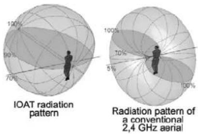
text_image
IOAT radiation pattern Radiation pattern of a conventional 2,4 GHz aerial7.4 Inserting dry / rechargeable cells
The SMART SX transmitter is powered by three AA-size dry cells; one set of cells is included in the set. Open the battery compartment on the back of the transmitter, and insert the dry cells as shown in the illustration on page 7. Close the battery compartment again. Remove the cells from the transmitter if you know you will not use it for a long period, e.g. during the Winter break.
Note:
It is essential to fit the batteries with correct polarity. The negative terminal of each cell must mate with the spring contact. Reversed polarity may ruin the transmitter and / or the cells.
It is also possible to use three rechargeable cells instead of the dry cells. However, these cells must always be recharged outside the transmitter, as no charge socket is present. Be sure to use a suitable battery charger.
7.5 Voltage monitor / operating times
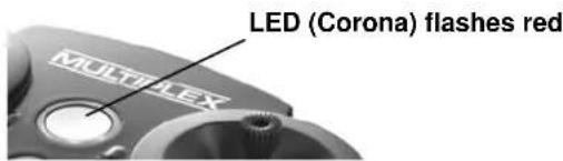
The SMART SX transmitter features a permanent warning function which alerts the user to low battery voltage. When the dry or rechargeable cells are almost flat, you will hear an audible warning, and the LED will flash red instead of yellow. If this should happen, land the model or cease operations without delay, and fit new or fully charged cells.
text_image
LED (Corona) flashes red MULTI-LEXThanks to the low energy requirement typical of 2.4 GHz equipment, the transmitter operates for the long period of up to 25 hours with three AA dry cells.
7.6 Binding
The first time you make the connection between transmitter and receiver the two components must be 'bound'. For safety's sake remove the propeller before doing this. When binding is complete, the receiving system immediately starts operating. First secure the model carefully so that no damage can result if the propeller should start turning. If you are unsure, for safety's sake remove the propeller first.
• Prepare the transmitter for binding
Switch the transmitter on with the multi-function button pressed in, and then release the button again. The Status LED flashes yellow at a high rate.
text_image
On / Off button Multi- function button• Prepare the receiver for binding
Switch the receiver on with the SET button pressed in. The LED on the receiver now also flashes yellow at a high rate.
text_image
MUDREXX RX-5 RX-LINK 1.00 4x +1.00 23 24 An Inverter Dialysis Dialysis Dialysis DialysisPlace the transmitter and receiver close to each other.
Transmitter power is greatly reduced for the binding process; the distance between the two units may need to be 20 cm or less. As soon as the transmitter and receiver have "found" each other, the flashing rhythm on both components changes to a slow rate. Any servos connected to the receiver will now follow the movement of the corresponding sticks.
The binding information is stored permanently in the receiver, i.e. the binding procedure only needs to be carried out once.
If you are using an ID receiver, you will hear an audible signal when binding is complete, and the transmitter automatically loads the appropriate settings. This means that you do not need to adjust settings 7.7 to 7.11 every time.
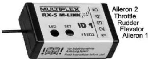
7.7 Channel assignment
The channel assignment of the SMART SX transmitter is fixed; the sequence is as follows:
Channel 1: Aileron 1
Channel 2: Elevator
Channel 3: Rudder
Channel 4: Throttle
Channel 5: Aileron 2
Channel 6: AUX auxiliary function (min. six-channel receiver required)
text_image
MULTIPLEX® RX-S M-LINK ID 1 LED SET #55822 Aileron 2 Throttle Rudder Elevator Aileron 1 Vor Indoorabnahme Anleitung Level! Fixed contactless before use!Connect the individual servos to the receiver in the sequence shown above.
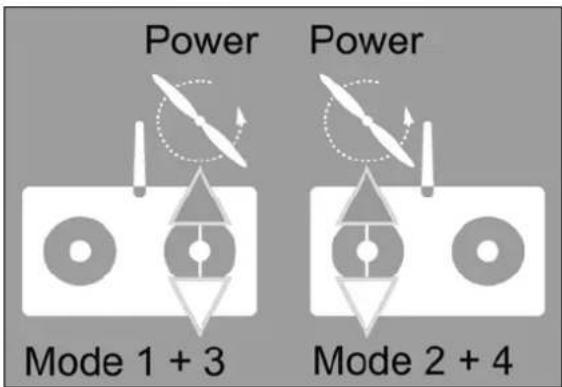
7.8 Mode switching
Basically there are four methods of assigning the control functions aileron, elevator, rudder and throttle to the two dual-axis sticks of the SMART SX transmitter. Which of these options is used varies according to the personal preference and habits of the model pilot. The stick modes are defined as follows:
Mode 1: Right stick Throttle vertical
| Aileron | horizontal | |
| Left stick Elevator vertical | Rudder | horizontal |
| Mode 2: Right stick Elevator vertical | ||
| Aileron | horizontal | |
| Left stick Throttle vertical | Rudder | horizontal |
| Mode 3: Right stick Throttle vertical | ||
| Rudder | horizontal | |
| Left stick Elevator vertical | Aileron | horizontal |
| Mode 4: Right stick Elevator vertical | ||
| Rudder | horizontal | |
| Left stick Throttle vertical | Aileron | horizontal |
The SMART SX transmitter is available in two versions, each offering two stick modes. When you purchase your set you must decide on one of the combinations, which is determined by the non self-cent-ring throttle function.
• SMART SX M-LINK Mode 1 + 3 (# 1 5300)
• SMART SX M-LINK Mode 2 + 4 (# 1 5301)
The stick mode can be changed within the selected combination. The first set (# 1 5300) can be switched between Mode 1 and 3. The second set (# 1 5301) can be switched between Mode 2 and 4.
text_image
Power Power Mode 1 + 3 Mode 2 + 4If you wish to change the stick mode, please use this procedure:
Locate the stick with two self-centring planes (no throttle function), and move it to the top right corner, then press the multi-function button for a period of three seconds: you
text_image
Press for three secondswill now hear an audible signal; the number of beeps indicates the new stick mode. It is only possible to swap rudder and aileron, as shown above, since the throttle function and the elevator are permanently assigned, depending on the set you have purchased. The setting is stored permanently for each model.
7.9 Servo reverse
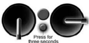
The direction of servo rotation can be changed for the three control surface functions (= all except throttle). If any control surface operates in the wrong direction, it is a simple matter to reverse the direction of operation for that function.
Locate the stick for the control function you wish to reverse, move it to one end-point, and hold the multi-function button pressed in for a period of three seconds, i.e. until the servo
text_image
Press for three secondsswitches to the opposite end-point. It will now respond in the desired direction. Servo reverse is not necessary for the throttle function, as the system always controls a speed controller the "right way round". The setting is stored permanently for each model.
7.10 Trims
The transmitter features digital trims for the three control surface functions. The trims are used to fine-tune the centre position of the servos. When you adjust the trims, you will hear a beep for every increment. For clarity you will hear different double-beeps at the centre position and both end-points. No trim is provided for the throttle function, as modern speed controllers for electric power systems adjust themselves automatically to the throttle stick's travel. The trim setting is stored permanently for each model.
7.11 Dual Rates
In the case of a model aircraft it may be useful to reduce the control surface travels at full movement of the sticks, e.g. when the model is flying at high speed. In contrast, full control surface travels are necessary when flying aerobatics. The Dual Rate function allows the pilot to switch between full and reduced control surface travels while the model is flying (Dual Rate does not affect the throttle func-
tion). Push down on one of the two sticks to switch the Dual Rate function on or off for the control functions operated by that stick.
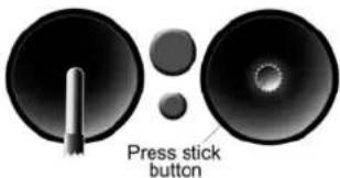
text_image
Press stick buttonAn audible signal indicates the current status: a brief beep indicates reduced servo travel; a long beep normal servo travel.
7.12 Fail-Safe
The receiver features a Fail-Safe function. If interference occurs, preventing the receiver picking up a valid M-LINK signal, the servos move to the previously programmed positions. In the case of a model aeroplane this usually means centred control surfaces, with the motor switched off. This significantly enhances safety when flying a model.
Move the transmitter controls to the point where the servos take up the desired fail-safe positions. When you are satisfied, press the SET button on the receiver: This action permanently stores the Fail-Safe positions in the receiver. However you can overwrite the settings at any time by setting new positions and pressing the button again.
text_image
MULTI-BOX 8X-5 IR-LINK 142 30V 1100Ω DC DC DC DC DC DC DC DC DC DC DC DC DC DC DC DC DC DC DC DC DC DC DC DC DC DC DC DC DC DC DC DC DC DC DC DC DC DC DC DC DC DC DC DC DC DC DC DC DC DC DSC DSC DSC DSC DSC DSC DSC DSC DSC DSC DSC DSC DSC DSC DSC DSC DSC DSC DSC DSC DSC DSC DSC DSC DSC DSC DSC DSC DSC DSC DSC DSC DSC DSC7.13 Auxiliary (AUX) channel
The SMART SX features one switched channel (= servo channel 6). This option can be used when an M-LINK receiver with six or more channels is used. The trim lever adjacent to the throttle stick controls the switched function.
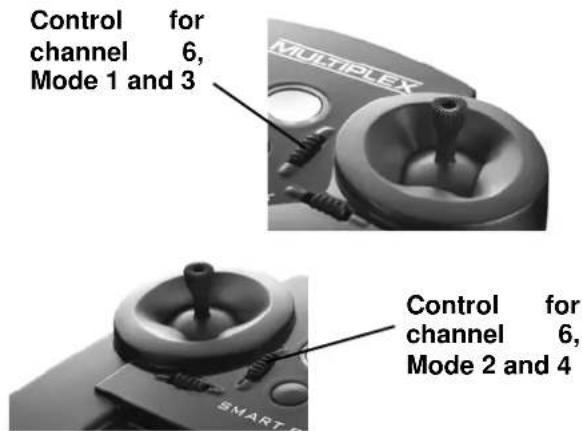
text_image
Control for channel 6, Mode 1 and 3 MULTIPLEX Control for channel 6, Mode 2 and 4This function can be used to switch working systems on and off, such as a model's lighting system, retractable undercarriage, etc.
7.14 Range checking
Before launching a model you should always check the range of the radio control system. Regular range checks are very important - even when using a 2.4 GHz system - to ensure that the RC system continues to work properly, and to allow you to detect problems in good time.
To carry out a range check, switch the transmitter on, then immediately press the multi-function button for a period of two seconds, i.e. until the Status LED glows constantly. The transmitter now emits an audible warning signal every ten seconds to alert you to the fact that it is in range-check mode, and is only transmitting at low power.
text_image
Press for two seconds immediately after switching onIn this state the model control system must continue to work up to a range of about fifty metres. If, and only if, this is the case, the system will operate at full range - beyond the limits of vision - when the transmitter is in normal operating mode. Switch the transmitter off to disable range check mode; when you switch on again, the system will be ready for normal use.
7.15 Model memory (ID)
The set is supplied complete with a compact 2.4 GHz M-LINK receiver with the UNI connector system, whose small case and in-line servo sockets make it ideal for use in relatively small models. However, the outstanding feature of this intelligent

natural_image
Illustration of a light bulb with the letters 'ID' and a starburst background (no text or symbols on the bulb itself)receiver is its ID (model identification) capability.
This feature enables the SMART SX transmitter to recognise your model, and switch to the corresponding model memory. This eliminates the constant requirement to alter servo directions and adjust trim settings, which is typical of beginners' transmitters. If you possess several models fitted with ID receivers, and switch to a different model, you simply need to switch the transmitter off and then on again. As soon as you hear the audible ID detect signal, your model is ready to fly. The settings for compatible MULTI-PLEX RTF and RR+ models are already programmed into the transmitter when you purchase it, i.e. you do not have to carry out any adjustments at all for these models.
However, it is also possible to overwrite or fine-tune the model data sets at the transmitter, which means that an ID receiver can be used in any model.
Other M-LINK receivers (light or telemetry) can also be operated in conjunction with the SMART SX transmitter. If you use a non-ID receiver, the SMART SX remains at the standard model memory "0" when it is switched on, and the audible ID detect signal is disabled. Here again all adjustment facilities are available, and the settings are stored automatically and permanently.
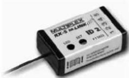
All compatible MULTIPLEX ELAPOR® RTF and RR+ models are programmed into the transmitter at the factory. The following receiver / IDs are available:
The receiver supplied in the set with the code 'ID 1' (# 5 5822) activates model memory 1 in the transmitter, to which no model is assigned. This ID code is free, i.e. any model can be operated with this receiver, and the user has
to program model memory 1 in the transmitter and set it up himself.
RX-5 M-LINK ID 1 (# 5 5822)
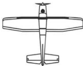
natural_image
Line drawing of a propeller airplane viewed from above (no text or symbols)No model assignment
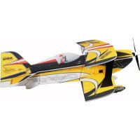
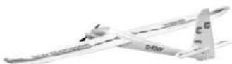
The receiver with the code 'ID 2' (# 5 5823) activates model memory 2 in the transmitter, to which the model 'Easy Star II' is assigned.
text_image
NECOSK RX-3 M-LINK ID 2 100 147 +11603 +11603RX-5 M-LINK ID 2 (# 5 5823)

natural_image
Model airplane with extended wings and visible propellers (no text or symbols)Model: Easy Star II
The receiver with the code 'ID 3' (# 5 5824) activates model memory 3 in the transmitter, to which the model 'Easy Glider' is assigned.

text_image
RZ-3 54.000 LED S2 ID 3 118001 AC-7600000000000000000000000000000000000000000000000000000000000000RX-5 M-LINK ID 3 (# 5 5824)
Model: Easy Glider
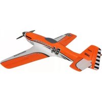
The receiver with the code 'ID 5' (# 5 5826) activates model memory 5 in the transmitter, to which the model 'Razzor' is assigned.

text_image
KONEX-5X RX-5 M-LINK 120V ID S 120V 120V 120V LED 600 +1000V +100VRX-5 M-LINK ID 5
(# 5 5826)

natural_image
Model of a black-and-white propeller airplane with checkered wings (no text or symbols on the aircraft body)Model: Razzor
The receiver with the code 'ID 6' (# 5 5827) activates model memory 6 in the transmitter, to which the model 'FunCopter' is assigned.

text_image
NOCTEX EX RZ-5 M LINK 100Ω 120V 100Ω 120V 100Ω 120V 100Ω 120VRX-5 M-LINK ID 6 (# 5 5827)

natural_image
Illustration of a helicopter with visible cockpit and propeller (no text or symbols)Model: FunCopter
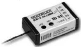
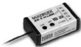
The receivers with the codes 'ID 21' (# 5 5828) and 'ID 22' (# 5 5829) activate model memories 21 and 22 in the transmitter respectively, to which no models are assigned; they are freely available, like the receiver with 'ID 1'.
text_image
RHYBEX RX-5 M-L1000 (1) LIO 35° 1D 24° 11/1000 °CRX-5 M-LINK ID 21 (# 5 5828)
text_image
KONEX UKS-5 UKM (1D 22) LTD 64 +1100V 4.5VRX-5 M-LINK ID 22 (# 5 5829)
7.16 Installing the receiver in the model
If you intend to fly a MULTIPLEX RTF or RR+ model, the receiver is installed in the correct manner as standard. If you wish to fly a different model, you must install an M-LINK receiver as described in the corresponding MULTIPLEX operating instructions. Please pay particular attention to the aerial deployment:
- Do not shorten or extend the aerial or its feed cable! If you need a longer or shorter aerial lead, please contact the MULTIPLEX Service Department, or a MULTIPLEX Service Centre.
- Install the receiver in the model in such a way that the aerial is as far away as possible from any conductive material.
- If your model's fuselage is made of electrically conductive material (e.g. carbon fibre), then the aerial must be installed in such a way that the active part (the final 30 mm) is located outside the model.
- Do not deploy the aerial parallel to servo leads, high-current cables or electrically conductive parts (e.g. pushrods).
All other information can be found in the instructions supplied with your receiver.
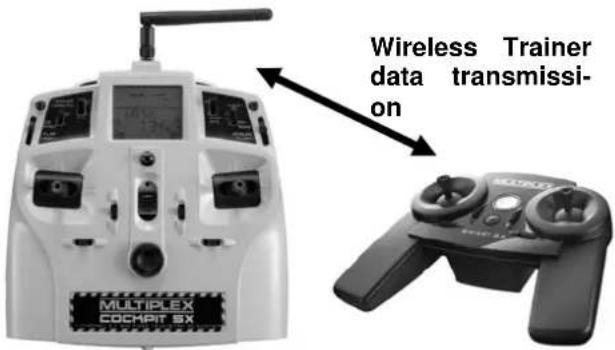
7.17 The SMART SX as Pupil transmitter
The SMART SX transmitter is prepared as standard for use in a wireless Trainer system; the Teacher transmitter can be any MULTIPLEX M-LINK transmitter fitted with a multifunction socket. The MULTIPLEX Trainer Stick can be plugged into this socket on the Teacher transmitter. A SMART SX transmitter will detect the presence of the stick, and switch automatically to Pupil mode. If you are using a PROFI TX transmitter with integral COPILOT, the same
functions can be used just as conveniently. Once again, please refer to the instructions supplied with the systems mentioned above for more information.
text_image
MULTIPLEX COCHPIT SX Wireless Trainer data transmissi- onTrainer mode operations in conjunction with a MULTIPLEX Cockpit SX transmitter.

text_image
PROFIT TX 12 Wireless Trainer data transmis- sionTrainer mode operations in conjunction with a MULTIPLEX PROFIT TX transmitter, with Trainer module.
7.18 Firmware Update / settings for future RR+ models
New firmware updates can be loaded into the memory of the SMART SX transmitter. This enables you at any time to bring the transmitter up to the latest technical standard. The settings for future RR+ models can also be loaded into the transmitter. You will need a USB
adapter with Uni connector (see Chapter 5, Accessories) to connect the SMART SX transmitter to a PC (see Chapter 5).
The settings for future RR+ models or a firmware update is carried out under menu control with the help of the MPX-Launcher PC program. This software is available on our website (www.multiplexrc.de) as a free download. Take a look at the site, as you may already find that a new firmware update is available for the SMART SX transmitter.
7.19 Installing aluminium sticks
A set of optional aluminium stick tops can be fitted to the transmitter. These upgrade items are available in the following colours: black (# 7 3305) and orange (#7 3306). The following figure shows the transmitter with black aluminium sticks.

natural_image
Black Multiplex Smart 8X controller with two dual motors and a central hub (no visible text or symbols)This is the procedure for fitting the new stick tops: the plastic stick top is a simple push-fit, and can easily be withdrawn; simultaneously twisting it eases the process. The aluminium stick top can now be slid into place, and retained by tightening the grubscrew on the side.
7.20 Speech output of telemetry data
You can still exploit the advantages of telemetry even if you use a SMART SX system. The basic requirement for this is the use of a telemetry-capable M-LINK 2.4 GHz receiver in the model, and - if desired - the corresponding MSB sensors. If you want the telemetry values to be generated as speech output, you need to use the special 'Souffleur' telemetry receiver (# 45185): this unit picks up the telemetry data from the
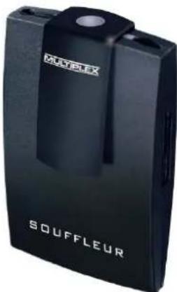
text_image
MULTIPELEX SOUFFLEURmodel, completely independently of the transmitter, and generates the values in spoken form in real time, as well as vario tones and warning indicators. Please refer to the operating instructions supplied with the device for all further details.
8. ADVICE AND SERVICE
We have taken great trouble to formulate these operating instructions in such a way that you can quickly and easily find answers to any questions which might arise. However, if you still have a query regarding your SMART SX M-LINK, please contact your model shop in the first instance, where you will find practical advice freely given.
The addresses of our Service Centres can be found on our website:
www.multiplex-rc.de
under CONTACT / SERVICE
9. CARE AND MAINTENANCE
The transmitter requires no special maintenance. We strongly recommend that you have your unit checked at regular intervals by an authorised MULTIPLEX Service Centre. This should occur every two or three years; more often if you use the system heavily. Regular checks of all working systems and radio range are mandatory in any case.
The best method of removing dust and dirt is to use a soft paintbrush. Stubborn soiling, such as grease and oil, can be removed with a moist cloth and - if necessary - a mild household cleaning agent. On no account use powerful cleaning agents such as white spirit or other solvents!
Avoid subjecting the transmitter to shock and pressure. The transmitter should always be stored and transported in a suitable protective container (transmitter case or bag).
10. CE CONFORMITY DECLARATION
This device has been assessed in accordance with European harmonised directives. This means that you are the owner of a product whose design satisfies the protective requirements of the European Community for the safe operation of equipment.
You can view the full CE Conformity Declaration in the form of a PDF file on the Internet at www.multiplexrc.de in the DOWNLOADS area under PRODUCT INFO.

11. GUARANTEE / LIABILITY EXCLUSION
The company MULTIPLEX Modellsport GmbH & Co. KG accepts no liability of any kind for loss, damage or costs which are due to the incorrect use and operation of this product, or which are connected with such operation in any way. Unless the law expressly states otherwise, the liability on the part of MULTIPLEX Modellsport GmbH & Co. KG to pay damages, regardless of the legal argument employed, is limited to the invoice value of those products supplied by MULTIPLEX Modellsport GmbH & Co. KG which were di-
rectly involved in the event in which the damage occurred. This does not apply if unlimited liability is incurred according to statutory law on account of intentional or gross negligence.
We guarantee our products in accordance with the currently valid statutory regulations. If you wish to make a claim under guarantee, your initial course of action should always be to contact the dealer from whom you purchased the equipment.
The guarantee does not cover faults and malfunctions which are caused by the following:
- Incorrect or incompetent use
- Maintenance carried out incorrectly, belatedly or not at all, or not carried out by an authorised Service Centre
- Incorrect connections
- The use of accessories other than genuine MULTIPLEX items
- Modifications or repairs which were not carried out by MULTIPLEX or by an authorised MULTIPLEX Service Centre
• Accidental or intentional damage
• Defects due to normal wear and tear - Operation of the unit outside the limits stated in the specification, or in conjunction with equipment made by other manufacturers.
12. DISPOSAL
Electrical equipment marked with the cancelled waste bin symbol must not be discarded in the domestic waste; the owner should use the appropriate specialised disposal system.
In the countries of the EU (European Union) electrical apparatus must not be discarded via the normal domestic waste system (WEEE - Waste of Electrical and Electronic Equipment, Directive 2002/96/EU). You can take your unwanted equipment to your nearest public collection point or recycling centre, where the staff will dispose of it in the proper manner at no charge to you.
The same applies to the batteries you use, which must never be discarded in the domestic waste. Instead please take them to the appropriate collection point. By disposing of your old equipment in a responsible manner you can make an important contribution to safeguarding the environment.
13. FAULT FINDING
Although the system is simple to use and extremely secure and reliable, you may still encounter the occasional problem when using the SMART SX. The table below lists a few possible problems, together with their causes and remedies. Please check the table, as the cause of a problem is often a mistake in handling, and the table is designed to help you locate errors which are often extremely simple.
| Fault | Reason | Remedy | |
| 1 | Transmitter cannot be switched on | Dry / rechargeable cells completely flat | Fit new dry cells, charge rechargeable cells, check cells are correctly inserted |
| 2 | Control surface travels too small | Dual Rates active | Check Dual Rate settings, see Chapter 7.11 |
| 3 | The system fails to work over the distance specified for the range check | The receiver aerial may not be installed correctly | Try a different aerial position; see Chapter 7.16 |
| 4 | Model cannot be controlled | Receiver not bound to transmitter Flat airborne battery | Carry out Binding procedure, Charge airborne battery |
| 5 | Binding cannot be carried out | Distance between transmitter and receiver too great | Reduce the distance to 20 cm or less |

natural_image
Symbol of a trash bin with crossed lines indicating no waste or discharge, and a solid rectangle below (no text or labels)The MULTIPLEX team hopes you have many hours of pleasure with your SMART SX radio control system.
Errors and amendments reserved
1. SOMMAIRE
1. Sommaire
2. Accès rapide 29
3. Introduction
3.1 Conception de la SMART SX 30
natural_image
Interior view of a battery pack with three cylindrical cells (no visible text or symbols)31
3. Binding
Concept for the future!
natural_image
Illustration of a light bulb with the letters 'ID' and a starburst background (no text or symbols)text_image
100% 90% 70%natural_image
Black KUETPEX drone with dual motors, battery pack, and small electronic device (no visible text or symbols)natural_image
White model airplane with attached control panels and battery pack (no visible text or symbols)Type de transmission: FHSS M-LINK
Alimentation: 3 éléments, Mignon (AA)
Consommantion: 85 mA
Poids: 355 g (piles incluses)
Dimensions (L x l x h): 193 x 148 x 53 mm
natural_image
Interior view of a battery pack with three cylindrical batteries and an open casing (no visible text or symbols)natural_image
Illustration of a light bulb with the letters 'ID' emerging from its body, surrounded by a starburst background (no text or symbols on the bulb itself)natural_image
Line drawing of a propeller airplane (no text or symbols)natural_image
Two white toy airplanes with curved blades, no visible text or markingsModèle Easy Star II
natural_image
Model airplane illustration with checkered wings and tail fin, labeled 'Modèle' below (no other text or symbols)Modèle Razzor
natural_image
Black and white illustration of a helicopter with visible cockpit, wings, and propellers (no text or symbols)Modèle FunCopter
natural_image
Black multi-plex speed controller with two motors and a brand logo (no visible text or symbols on the device body)natural_image
Black SOUFFLEUR device with visible branding (no text or symbols on body)8. CONSEILS ET SERVICE
natural_image
Symbol of a waste bin with crossed lines indicating no waste, and a solid black rectangle below (no text or labels)natural_image
Interior view of a battery pack with three cylindrical batteries (no visible text or symbols)- Collegamento
natural_image
Close-up of two black electronic components with circular tops and a cylindrical shaft, labeled 'Tenere premuto' (no other text or symbols visible)natural_image
Two black speaker stands with a probe inserted, no visible text or symbols on the stands themselves.natural_image
Illustration of a light bulb with a 'ID' symbol emerging from its tip, surrounded by radiating lines (no text or symbols beyond the graphic)natural_image
Black handheld drone with dual motors, battery pack, and small electronic device (no visible text or symbols)- Trasmittente SMART SX M-LINK
• Ricevente RX-5 light M-LINK ID 1 - Tre pile a secco AA
• Istruzioni multilingue
natural_image
Model of a white quadcopter-9 aircraft with attached control panels and battery pack (no visible text or symbols)Stick Gas / alettone (Mode 1 + 3)
Stick elevatore / timone (Mode 2 + 4)
Trim alettone
(Mode 1 + 3)
Trim timone
(Mode 2 + 4)
natural_image
Interior view of a battery pack with three cylindrical batteries, one partially open and one inserted (no visible text or symbols)text_image
Imadianians 100% 90% 70% 100% 70% 5%Irradiazione IOAT
natural_image
Two black speaker blades with a pointed tip, showing sound waves (no text or symbols)natural_image
Illustration of a light bulb with a 'ID' symbol emerging from its tip, surrounded by radiating lines (no text or symbols beyond the graphic)natural_image
Line drawing of a propeller airplane viewed from above (no text or symbols)natural_image
White model airplane with visible propellers and tail fin, no text or symbols presentModello: Easy Star II
text_image
MCHIPEX RDS-5 M-LINK LED 100V +160V +20V +25V +30VRX-5 M-LINK ID 5
(# 5 5826)

natural_image
Modello airship with checkered wings and tail fin, no visible text or symbols on the aircraft bodyModello: Razzor
natural_image
Illustration of a helicopter with visible cockpit and propeller (no text or symbols)Modello: FunCopter
text_image
MultipLEX COCMPT 6X Trasmissioni dati Wireless Trainernatural_image
Black multiflex smart transceiver device with two motors and a control panel (no visible text or symbols)natural_image
Symbol of a trash bin with crossed lines indicating no waste or discharge (no text or labels)1. TABLA DE CONTENIDOS
natural_image
Interior view of a battery pack with three cylindrical batteries (no visible text or symbols)- Asociación
natural_image
Illustration of a light bulb with a 'ID' symbol emerging from its tip, surrounded by radiating lines (no text or symbols beyond the graphic)text_image
100% 90% 70%natural_image
Black handheld drone with control panels and battery components, no visible text or symbolsnatural_image
Model of a white unmanned aerial vehicle with attached control panels and propeller components (no visible text or symbols)natural_image
Interior view of a battery pack with three cylindrical batteries, no visible text or symbolstext_image
100% 90% 70%text_image
100% 70% 5% 100%natural_image
Illustration of a light bulb with the letters 'ID' and a starburst background (no text or symbols on the bulb itself)natural_image
Line drawing of a propeller airplane viewed from above (no text or symbols)natural_image
White model airplane with black markings, no visible text or symbolsModelo Easy Star II
natural_image
Model airplane illustration with checkered wings and tail, labeled 'Modelo' below (no other text or symbols)Modelo Razzor
text_image
MAX-3 10.5 MHz LTD 10 ID 6 4-1000 200V/100V/100V MAX-3 10.5 MHz LTD 10 Power ControlRX-5 M-LINK ID 6 (# 5 5827)

natural_image
Illustration of a futuristic high-speed helicopter with visible cockpit and landing gear (no text or symbols)Modelo FunCopter
natural_image
Black Multiplex Smart Six controller device with dual motors and control knobs (no visible text or symbols on device body)ZUBEHÖR / ACCESSORIES / ACCESSORES
| #7 5305 | Smart SX Alu-Stick (2)black | 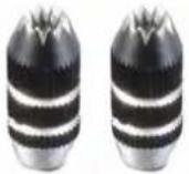 |
| #7 5306 | Smart SX Alu-Stick (2)orange |  |
| #72 4391 | Smart SX Sticker Decor 1EasyStar II |  |
| #72 4392 | Smart SX Sticker Decor 2EasyGlider PRO „Blue“ |  |
| #72 4393 | Smart SX Sticker Decor 3Carbon black |  |
| #72 4394 | Smart SX Sticker Decor 4Carbon red |  |