AcroMaster Pro - Model making MULTIPLEX - Free user manual and instructions
Find the device manual for free AcroMaster Pro MULTIPLEX in PDF.

| Product type | Radio-controlled model airplane (scale modeling) |
| Brand | Multiplex |
| Model | AcroMaster Pro |
| Category | Scale modeling |
| Wingspan | 1100 mm |
| Overall length | 1150 mm |
| Flying weight | Approximately 1350 g |
| Wing area | 36.6 dm² |
| Wing loading | 36.9 g/dm² |
| Power supply | LiPo 3S 2600 mAh 40C battery (recommended ROXXY EVO) |
| Motor | Roxy BL Outrunner C35-48-990kV |
| ESC | Roxy BL-Control 755 S-BEC |
| Propeller | 12x6 inches (fiber-reinforced plastic) |
| Servos | 2x HS-82 MG (ailerons), 2x HS-65 HB (elevator and rudder) |
| RC functions | Ailerons, elevator, motor, rudder |
| Material | ELAPOR® (particle foam) |
| Minimum age | 14 years (adult supervision for minors) |
| Assembly | Pre-assembled, requires gluing tail surfaces and mounting wings |
| Recommended glue | Zacki ELAPOR® (medium viscosity cyanoacrylate glue) |
| Center of gravity | 110 mm behind the leading edge |
| Normal control throws | Ailerons ±30 mm, elevator ±40 mm, rudder ±55 mm |
| 3D control throws | Ailerons ±50 mm, elevator ±60 mm, rudder ±85 mm |
| Spare parts | Available: propeller, motor, ESC, servos, etc. |
| Maintenance | Check attachment of control horns, servos, pushrods; concentricity of cone |
| Cleaning | Avoid water on electronics; use a dry cloth |
| Safety | Do not use under influence of alcohol/drugs, keep away from people and animals, comply with regulations |
Frequently Asked Questions - AcroMaster Pro MULTIPLEX
User questions about AcroMaster Pro MULTIPLEX
0 question about this device. Answer the ones you know or ask your own.
Ask a new question about this device
Download the instructions for your Model making in PDF format for free! Find your manual AcroMaster Pro - MULTIPLEX and take your electronic device back in hand. On this page are published all the documents necessary for the use of your device. AcroMaster Pro by MULTIPLEX.
USER MANUAL AcroMaster Pro MULTIPLEX
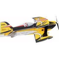
natural_image
Model airplane with visible branding and propeller, no readable text or symbols on the aircraft bodyACROMASTER
PRO

Bauanleitung
Abbildungen 14 - 17
Ersatzteile 18 - 19
5

Assembly instructions 9
Illustrations 14 - 17
Replacement parts 18 - 19

Safety information for MULTIPLEX airplane models
When operating the model, all warning and safety information in the operating instructions must be observed.
The model is NOT A TOY in the conventional sense. If you use your model carefully, it will provide you and your spectators with lots of fun without posing any danger. If you do not operate your model responsibly, this may lead to significant property damage and severe injury. You and you alone are responsible for following the operating instructions and for ensuring the safety guidelines are adhered to.
When setting up the model, operators declare they are familiar with and understand the contents of the operating instructions, particularly regarding safety information, maintenance work, operating restrictions, and deficiencies.
This model may not be operated by children under the age of 14. If minors operate the model under the supervision of a responsible and competent adult pursuant to the law, this person is responsible for adhering to the information in the operating instructions.
THE MODEL AND THE ASSOCIATED ACCESSORIES MUST BE KEPT OUT OF REACH OF CHILDREN UNDER 3 YEARS OF AGE! CHILDREN UNDER 3 COULD SWALLOW REMOVABLE SMALL PARTS OF THE MODEL. RISK OF SUFFOCATION!
Multiplex Modellsport GmbH & Co. KG is not liable for loss, damage and consequential damage of any kind caused by incorrect operation, improper use or misuse of this product, including the accessories used along with it.
Proper use
The model may only be used in the hobby sector. No other type of use is permitted. To operate the model, only the accessories recommended by Multiplex may be used. The recommended components have been tested and adjusted for safe functioning together with the model. If other components are used or the model is modified, all claims against the manufacturer or retailer are void.
In order to minimize the risk when operating the model, observe the following points in particular:
- The model is controlled via a remote control. No remote control is safe from radio interference. Interference may lead to a loss of control of the model. Therefore, always ensure large safety distances in all directions when operating the model. As soon as even the smallest indication of radio interference presents itself, operation of the model must be halted immediately!
- The model may only be put into operation after a complete function and range test has been successfully carried out as per the instructions for the remote control.
- The model may only be flown in good visibility. Do not fly in poor light or in the direction of the sun in order to avoid glare.
- The model may not be operated under the influence of alcohol or other intoxicants. The same applies for medicines that impair perception and responsiveness.
- Only fly the model in wind and weather conditions in which you can safely control it. Even with light wind, take into account that turbulence may build up on objects and have an effect on the model.
- Never fly in places where this would pose a danger to others, i.e. in residential areas, near power lines, roads, and railroad tracks.
- Never direct the model at people or animals! Avoid unnecessary risks and alert other pilots to potential hazards. Always fly in a manner that ensures neither you nor others are exposed to danger – even many years of accident-free flying experience are no guarantee for the next minute of flying time.
Residual risks
Even if the model is operated in accordance with the regulations and observing all safety aspects, there is always a residual risk.
Third-party liability insurance (powered model airplane) is therefore mandatory. If you are a member of a group or association, you might be able to take out the appropriate insurance there.
Ensure models and the remote control are properly maintained and are in good condition at all times.
Due to the construction and design of the model, the following dangers may arise in particular:
Injuries caused by the propeller: As soon as the battery is connected, the area around the propeller must be kept clear. Be aware that objects in front of the propeller may be sucked in and objects behind the propeller may be blown away. Always align the model ensuring it cannot move in the direction of other people if the motor starts up unintentionally. When performing adjustments for which the motor is running or may start up, the model must always be securely held in place by a helper.
- Crashes caused by control errors: Even the most experienced pilots can make mistakes. For this reason, only fly in a safe environment and at authorized model airplane flying fields.
- Crashes caused by technical failures, undetected damage from transportation or pre-existing damage: The model must be carefully inspected before each flight. Bear in mind that technical or material failures may occur at any time. Therefore, only operate the model in a safe environment.
- Adhere to operating limits: Excessively harsh flying weakens the structure of the model and may lead to technical and material failures as well as crashes immediately or, due to 'insidious' consequential damage, in later flights.
- Risk of fire due to malfunction of the electronics: Batteries must be stored safely. The safety information of the electronic components in the model, the battery, and the charging device must be observed.

Safety information for MULTIPLEX airplane models
The electronics must be protected from water. The controller and the batteries must be sufficiently cooled.
The instructions of our products may not be reproduced and/or published – not even in part – in print or electronic media without the express (written) permission of Multiplex Modellsport GmbH & Co. KG.
Safety information for MULTIPLEX construction kits
Familiarize yourself with the construction kit!
MULTIPLEX model kits are subjected to constant material inspection during production. We hope that you are satisfied with the contents of the kit. We nevertheless ask that you check all parts (according to the parts list) before use, as used parts cannot be exchanged. If a part is not OK, we will be happy to fix or replace it after verifying this. Please send the part with sufficient postage to our Service department. Be sure to include a short description of the fault along with the purchase receipt. We are continuously working on further developing the technology of our models. We reserve the right to make changes to the contents of the kit in terms of shape, dimension, technology, material, and equipment at any time and without warning. Please understand that no claims can be derived from specifications and illustrations in these instructions.
Caution!
Remote-controlled models, particularly airplane models, are not toys in the conventional sense. Their construction and operation requires technical understanding, a minimum level of artisan skills, discipline, and safety-awareness. Errors and negligences during building and operation may result in personal injury or property damage. As the manufacturer has no influence on proper assembly, maintenance, and operation, we explicitly refer to these dangers.
Warning:
Like any airplane, the model has static limitations! Nosedives and reckless maneuvers may result in damage to the model. Please note: In such cases, there is no replacement. Approach the limitations with caution. The model is fitted with the propeller recommended by us but can only withstand the loads if it is built flawlessly and is undamaged.
Crooked – does not really exist. If individual parts are bent during transit, they can be straightened again. Here, ELAPOR ^® behaves like metal. If you overbend the material slightly, it springs back minimally and retains its shape. The material of course has its limits – so don't overdo it!
Crooked – does indeed exist! If you want to paint your model, you do not need any primer for pretreatment when using the EC colors. Matt paints result in the best look. Under no circumstances may the paint coats be too thick or applied unevenly, otherwise the model will go out of shape and will be crooked, heavy or even unusable!
This model is not made of Styrofoam™! Therefore, adhesions using white glue, polyurethane or epoxy are not possible. These glues only stick superficially and may peel off in severe cases. Only use cyanoacrylate/ superglue of medium viscosity, preferably Zacki-ELAPOR® # 85 2727, the superglue optimized and adapted for ELAPOR® particle foam. When using Zacki-ELAPOR®, you can largely do without kickers or activators. If, however, you use other adhesives, and are unable to do without kickers/ activators, only spray outdoors for health reasons. Take care when working with all cyanoacrylate adhesives. These adhesives sometimes harden in seconds, so do not bring your fingers or other body parts into contact with them. To protect your eyes, be sure to wear protective goggles! Keep away from children! In some places, hot glue may also be used. If applicable, this is indicated in the instructions!
Working with Zacki ELAPOR®
Zacki ELAPOR ^® was developed specially for adhesion on our foam models made of ELAPOR ^® . In order to design the adhesion as optimally as possible, the following points should be taken into consideration:
- Avoid the use of activators. This causes the bonding to be significantly weakened. Especially for large-scale adhesion, we recommend allowing 24 hours for the parts to dry.
- Activators must only be used for point fixing. Only spray a little activator on one side. Allow the activator to flash off for approx. 30 seconds.
- For optimal bonding, sand down the surface using sandpaper (grain size 320).

text_image
ZACKI ELAPOR 100% Gas Chromatogram, a Gas Chromatogram Partikel Schahr
text_image
ZACKI85 2727
Accessories and tools
Required accessories Optional accessories
• 1x Zacki Elapor® 20 g # 85 2727
• 1x receiver RX-5 light M-LINK 2.4 GHz # 55 808
• 1x battery ROXXY EVO LiPo 3 - 2600M 40C # 316656
The following tools are required to assemble the model:
• Activator spray for CA adhesive
• Medium-sized cross-tip screwdriver
- Hex wrench 1.5
• 10 mm open-ended wrench or socket wrench
• 220-320 grit sandpaper
• WINGSTABI 7-channel #5 5010
• WINGSTABI RX-7-DR M-LINK # 5 5012
• Receiver RX-7-DR M-LINK 2.4 GHz # 5 5811
• Multiplex G sensor for M-LINK # 8 5409
• Propeller balancer # 33 2355
• Decal sheet blue-red # 1-00856
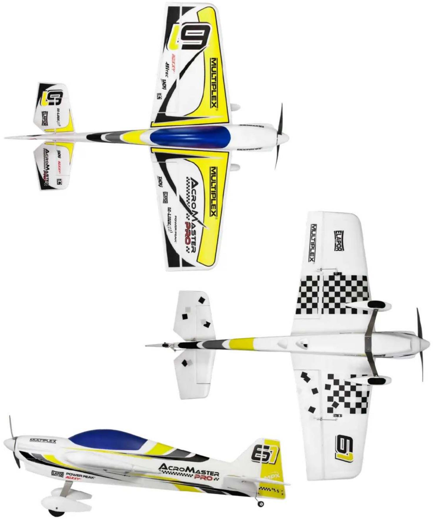
- Decal sheet yellow-silver #1-01012
Scope of delivery AcroMaster PRO RR
- ELAPOR ^ model (almost fully assembled)
• Drive motor Roxy BL C35-48-990kv
• Controller Roxy BL Control 755 S-BEC - 12x6" propeller
• 2 servos HS-82 MG
• 2 servos HS-65 HB
Specifications
| Wingspan: 1100 mm |
| Overall length: 1150 mm |
| Flight weight: Approx. 1350 g |
| Wing area: 36.6 dm2 |
| Wing loading: 36.9 g/dm2 |
| RC functions: Aileron, elevator, motor, rudder |
List of parts AcroMaster PRO
| Part No. | Qty. | Name | Material | Dimensions |
| 1 | 1 | Assembly instructions | Paper | DIN A4 |
| 2 | 1 | Complaints form for models | Paper | DIN A4 |
| 3 | 1 | ROXXY BL-Control 755 S-BEC instructions | Paper | DIN A4 |
| 4 | 1 | Fuselage fully assembled | Elapor | Finished component |
| 5 | 1 | Left wing fully assembled | Elapor | Finished component |
| 6 | 2 | Right wing fully assembled | Elapor | Finished component |
| 7 | 1 | Elevator fully assembled | Elapor | Finished component |
| 8 | 1 | Canopy fully assembled / painted | Elapor | Finished component |
| 9 | 1 | Rudder fully assembled | Elapor | Finished component |
| 10 | 1 | Holder for spinner | Plastic | Finished component |
| 11 | 1 | Spinner | EPP | ∅ 62 mm |
| 12 | 1 | Main spar | CFRP | ∅ 10x620 mm |
| 13 | 1 | Auxiliary spar | CFRP | ∅ 10x200 mm |
| 14 | 1 | Wing lock | Wood | Finished component |
| 15 | 1 | Battery board | Wood | Finished component |
| 16 | 1 | Undercarriage fully assembled | Aluminum / Plastic | Finished component |
| 17 | 2 | Self-tapping screws | Steel, galvanized | ∅ 2.9x16 mm |
| 18 | 1 | Propeller | Fiber-reinforced plastic | ∅ 12x6" |
| 19 | 1 | Propeller coupling | Aluminum | ∅ 5/6 mm |
| 20 | 3 | Mushroom head hook and loop tape | Plastic | 25x60 mm |
| 21 | 3 | Velour hook and loop tape | Plastic | 25x60 mm |
| 22 | 2 | Hook and loop strap | Plastic | Finished component |
Assembly instructions
Before assembly
Use the list of components on page 8 and Fig. 01 + 02 to check the completeness of the components supplied.
We recommend using a soft, clean and flat surface to ensure the model is not damaged during assembly. Always use, unless otherwise specifically stated Zacki ELAPOR® CA instant adhesive to glue the model.
1. Assembling the elevator
Slide the elevator 7 into the rear of the fuselage 4 and check the fit and that it is at a right angle to the fuselage. Pull it back out again from the rear and sand the contact surfaces slightly to ensure the adhesive adheres better later on. Make sure it fits correctly again. If you are satisfied, apply Zacki ELAPOR® to the fuselage and then insert the elevator Fig. 03. If necessary, use a paper towel to remove any excess adhesive. Ensure that it is at a right angle to the fuselage and that the lengths A and B are identical Fig. 04 + 05. A little activator spray speeds up the process.
Use the remote control to set the elevator servo to the neutral position. Make sure the elevator flap is also in the neutral position and screw the pushrod to the elevator horn.
2. Assembling the rudder
Proceed with the rudder in the same way as with the elevator. This means, initially check correct fit, then sand accordingly, apply adhesive, and align Fig. 06. Ensure that it is also at a right angle to the fuselage Fig. 07.
Use the remote control to set the rudder servo to the neutral position. Make sure the rudder flap is also in the neutral position and screw the pushrod to the rudder horn.
3. Assembling the undercarriage
Screw the undercarriage 16 to the fuselage using the self-tapping screws 17 Fig. 08.
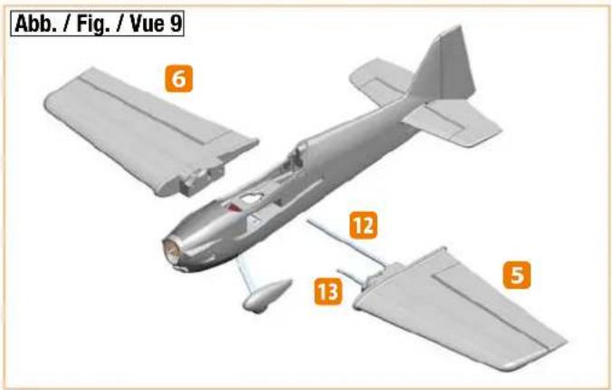
4. Assembling the wings to the fuselage
The long CFRP tube 12 is the rear main spar and the short CFRP tube 13 is the front auxiliary spar. Slide the spars into one wing and insert it into the fuselage. Now slide on the other wing and make sure that both servo cables are routed upward into the fuselage Fig. 09. To secure the wings, insert the wing lock 14 from above into the slots of the two wings Fig. 10.
5. Assembling the propeller
Push the propeller coupling 19 as far as possible onto the motor shaft. Balance the propeller 18, e.g. using the propeller balancer # 33 2355 or similar. Slide on the propeller and then the holder for the spinner 10.
Slide on the washer and screw on the nut Fig. 11. Tighten the nut firmly. Finally, position the spinner 11 on the holder.
6. Assembling the receiver
Insert the servo plugs into the receiver and use the hook and loop tape 20 and 21 to fix it to the area provided for this purpose in the fuselage Fig. 12. The servo plugs are labeled as follows:
1 LH aileron; 2 Elevator; 3 Rudder; 4 Motor; 5 RH aileron
7. Assembling the battery
Use the hook and loop tape 20 and 21 to fix the battery to the battery board Fig. 15 and tighten the hook and loop strap 22 around both Fig. 13. Insert the battery into the battery rail Fig. 14 and also fix it into position using the hook and loop tape 20 and 21, as well as a hook and loop strap 22. To do so, thread the hook and loop strap through the slot in the battery board and in the Elapor and tighten firmly Fig. 15
8. Preflight check and center of gravity
Always check the model before flying it for the first time. Check the following points before the initial flight:
- Rudder horns tight
- Servo screws tight (cross-head screws)
- Linkage rod tight (hex grub screws)
- Make sure the spinner is running true by rotating the propeller by hand
Position and secure the battery (3S 2600 mAh 40C) and the receiver in the model using the hook and loop tape and strap so that the center of gravity at the fuselage is 110 mm behind the leading edge Fig. 16
9. Rudder deflections
Normal settings
| Aileron distances40% Expo | Mounting points |
| Aileron +/- 30 mm | Innermost servo Outside rudder horn |
| Elevator +/- 40 mm | Innermost servo Outside rudder horn |
| Rudder +/- 55 mm | Innermost servo Outside rudder horn |
3D settings
| Aileron distances60% Expo | Mounting points | ||
| Aileron +/- 50 | mm Servo 2nd | hole fromoutside | Outside rudder horn |
| Elevator +/- 60 | mm Outermost servo | Center rudder horn | |
| Rudder +/- 85 | mm Outermost servo | Center rudder horn | |
10. Initial flight
Carry out a range test and make sure all the rudders are running in the correct direction and are in the neutral position. Start the model from the ground and familiarize yourself with the flight characteristics at high altitude.
text_image
Exploded view diagram of a mechanical assembly with numbered parts for identification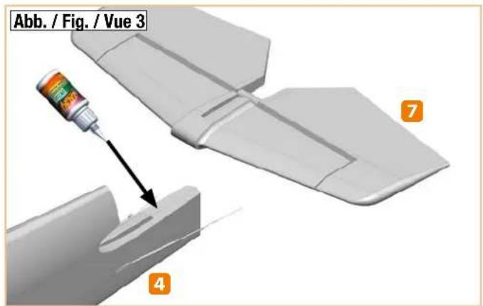
text_image
Abb. / Fig. / Vue 3 7 4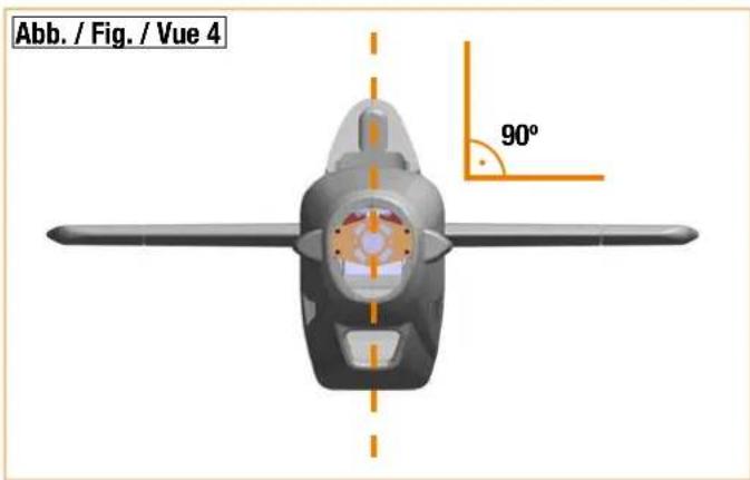
text_image
Abb. / Fig. / Vue 4 90°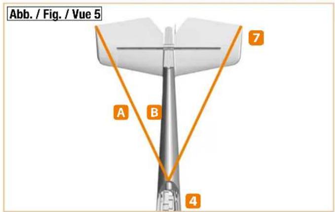
text_image
Abb. / Fig. / Vue 5 A B 4 7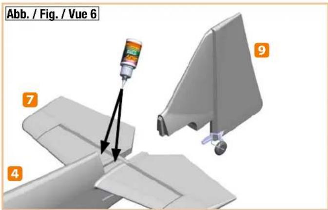
text_image
Abb. / Fig. / Vue 6 7 4 9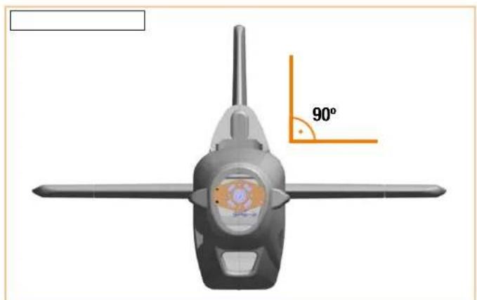
natural_image
Top-down view of a four-bladed aircraft with an orange 90-degree angle marker (no text or symbols on the aircraft body)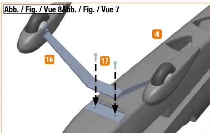
text_image
Abb. / Fig. / Vue 8Abb. / Fig. / Vue 7 16 17 4Abbildungen · Illustrations · Ilustrazioni · Ilustraciones
text_image
Abb. / Fig. / Vue 9 6 12 13 5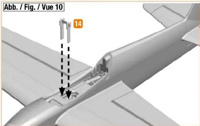
text_image
Abb. / Fig. / Vue 10 14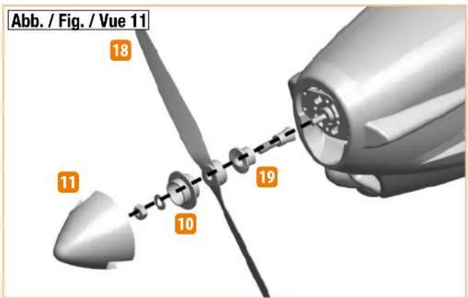
text_image
Abb. / Fig. / Vue 11 18 11 10 19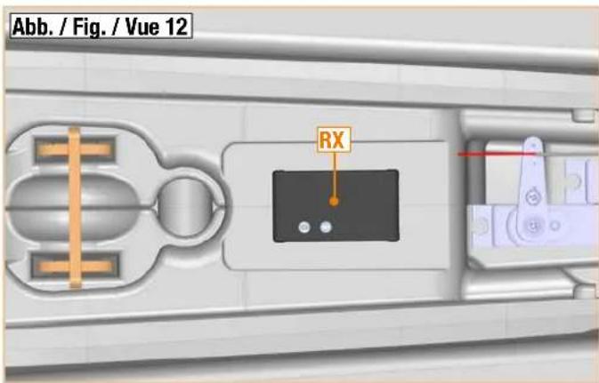
text_image
Abb. / Fig. / Vue 12 RX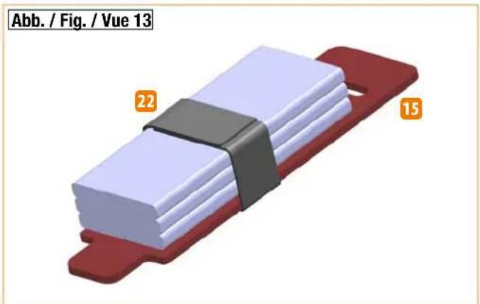
natural_image
3D model of a red and white mechanical component with black bands, labeled Abb. / Fig. / Vue 13 (no text or symbols on the object itself)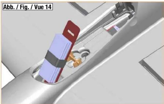
natural_image
3D mechanical assembly diagram showing a component inserted into a housing (no text or symbols visible)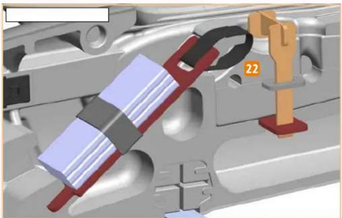
natural_image
3D mechanical assembly diagram showing a component with red and blue parts, no visible text or symbols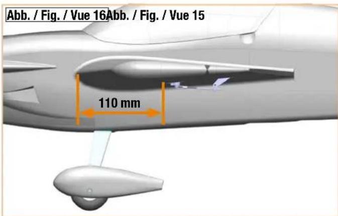
text_image
Abb. / Fig. / Vue 16Abb. / Fig. / Vue 15 110 mmDekorplatzierung • Decal positioning • Placement des autocollants • Posizionamento decalcabili • Colocación de la decoración
natural_image
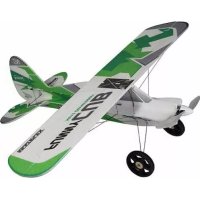
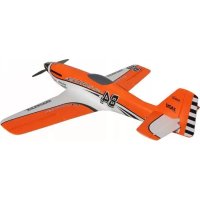
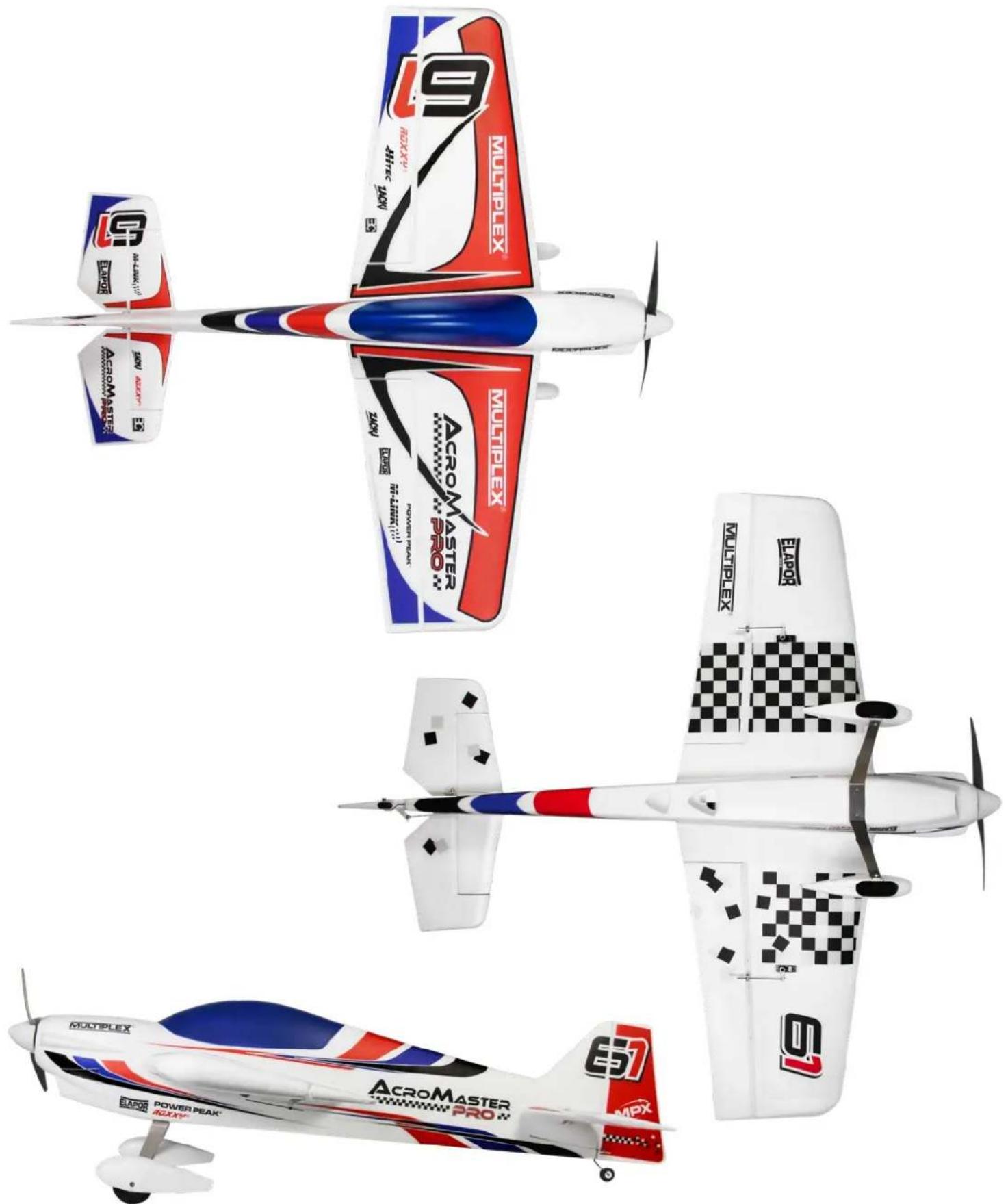
Four different propeller aircraft models from different manufacturers (e.g., Accelerator, Power Peak, Multiplex), shown in isometric view with no visible text or symbols on the aircraft themselves.Dekorplatzierung • Decal positioning • Placement des autocollants • Posizionamento decalcabili • Colocación de la decoración
natural_image
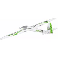
Four different propeller aircraft models from different angles, labeled with model name and registration number (e.g., 19 MULTIPLEX, 5 E20), shown in top, front, side, and perspective views respectively.Ersatzteile • Replacement parts • Pièces de rechange • Pezzi di ricambio • Repuestos
DE
natural_image
3D rendered mechanical part with no visible text or symbols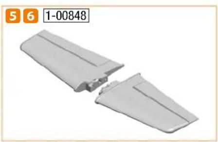
natural_image
Two gray plastic electronic components with cutouts, shown without any text or symbols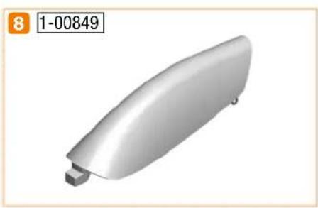
natural_image
3D rendered image of a silver-colored curved object with a small protrusion, labeled '8 1-00849' in the top-left corner (no other text or symbols)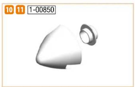
natural_image
3D rendered object resembling a conical or mechanical component with a flanged end (no text or symbols)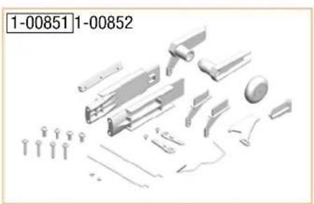
natural_image
Exploded view of mechanical components including screws, gears, and a dial (no text or symbols visible)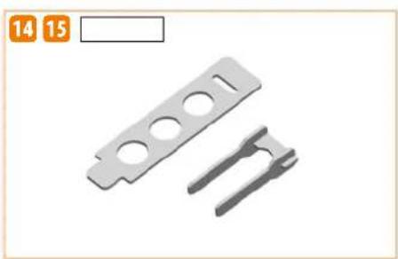
natural_image
Two metallic mechanical components with circular holes and triangular slots, no text or symbols visible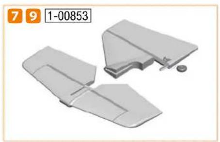
natural_image
3D model of a gray plastic component with cutouts and mounting bracket (no text or symbols)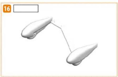
natural_image
Simple 3D diagram of two elongated objects connected by a line, with no text or symbols present.
natural_image
Four white plastic electronic devices with rounded ends, arranged diagonally (no text or symbols visible)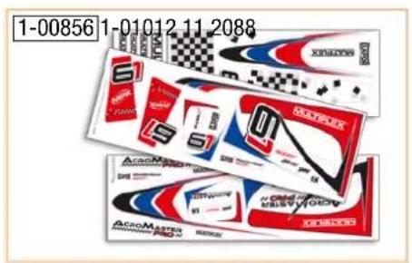
text_image
1-00856 1-01012 11 2088 S1 4 S MATELEX ACCO Master ACCO Master S1 S1 S1 S1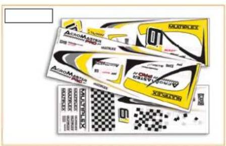
text_image
MULTIFLEX 01 ACROMATE MASCULARS 2000 MAXIMETER ACROMATE MASCULARS 2000 MAXIMETER MASCULARS 2000 MAXIMETER MASCULARS 2000 MAXIMETER MASCULARS 2000 MAXIMETER MASCULARS 2000 MAXIMETER MASCULARS 2000 MAXIMETER MASCULARS 2000 MAXIMETER MASCULARS 2000 MAXIMETER MAXIMETER 2000 MAXIMETER MAXIMETER 2000 MAXIMETER MAXIMETER 2000 MAXIMETER MAXIMETER 2000 MAXIMETER MAXIMETER 2000 MAXIMETER MAXIMETER 2000 MAXIMETER MAXIMETER 2000 MAXIMETER MAXIMETER 2000 MAXIMITER MAXIMITER 2000 MAXIMITER MAXIMITER 2000 MAXIMITER MAXIMITER 2000 MAXIMITER MAXIMITER 2000 MAXIMITER MAXIMITER 2000 MAXIMITER MAXIMITER 2000 MAXIMITER MAXIMITER 2000 MAXIMITER MAXIMITER 2000 MAXIMITEER MAXIMITEER 2000 MAXIMITEER MAXIMITEER 2000 MAXIMITEER MAXIMITEER 2000 MAXIMITEER MAXIMITEER 2000 MAXIMITEER MAXIMITEER 2000 MAXIMITEER MAXIMITEER 2000 MAXIMITEER MAXIMITEER 2000 MAXIMITEEER MAXIMITEEER 2000 MAXIMITEEER MAXIMITEEER 2000 MAXIMITEEER MAXIMITEEER 2000 MAXIMITEEER MAXIMITEEER 2000 MAXIMITEEER MAXIMITEEER 2000 MAXIMITEEER MAXIMITEEER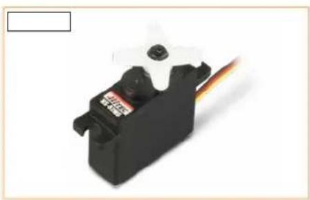
natural_image
Close-up of a black servo motor with white head and orange flame, no visible text or symbols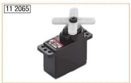
natural_image
Black and white photo of a mechanical device with a white handle and black body, labeled '11 2065' in the corner (no other text or symbols visible)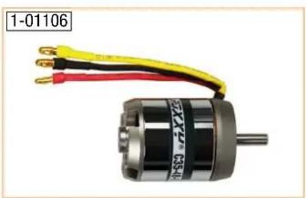
natural_image
Close-up of a black and yellow electric motor with three copper wires attached (no visible text or symbols)
text_image
73 4344 Abbildung kann vom Original abweichen. Picture may offer from original product. Les illustrations peuvent diverger de l'original. 31 3548 Abbildung kann vom Original abweichen. Picture may offer from original product. Les illustrations peuvent diverger de l'original.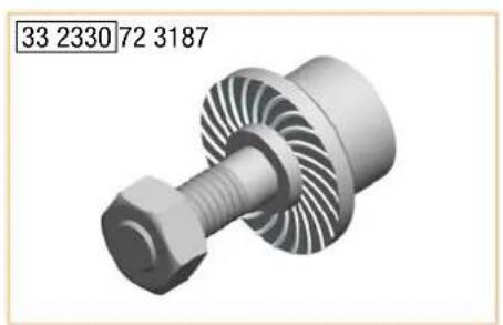
natural_image
3D rendered mechanical component with threaded shaft and hexagonal nut (no text or symbols)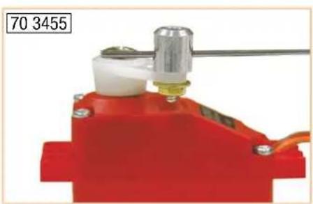
natural_image
Red mechanical device with a cylindrical component and attached wires, no visible text or symbols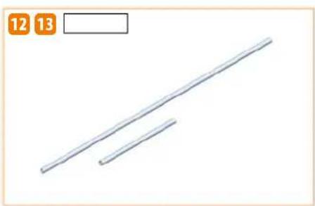
natural_image
Two parallel diagonal lines with a numbered label '12' and '13' in the top-left corner (no other text or symbols)text_image
ZACKI ELAPOR Elaborate Crude Oil Elaborate Crude Oil
text_image
ZACKI85 2727