FWD46B2TOUCH - Monitor SONY - Free user manual and instructions
Find the device manual for free FWD46B2TOUCH SONY in PDF.
Download the instructions for your Monitor in PDF format for free! Find your manual FWD46B2TOUCH - SONY and take your electronic device back in hand. On this page are published all the documents necessary for the use of your device. FWD46B2TOUCH by SONY.
USER MANUAL FWD46B2TOUCH SONY
Sony Corporation Printed in Taiwan © 2012 Sony Corporation4-424-539-03(1) Flat Wide Display Monitor
FWD-55B2 1,245mm×715.8mm×84mm 1,245mm×763.9mm×292.6mm
FWD-46B2 1,053.6mm×608.2mm×84mm 1,053.6mm×656.3mm×292.6mm
WARNING Owner’s Record The model and serial numbers are located on the rear. Record the model and serial numbers in the spaces provided below. Refer to these numbers whenever you call upon your Sony dealer regarding this product. Model No. Serial No. To reduce the risk of fire or electric shock, do not expose this apparatus to rain or moisture. To avoid electrical shock, do not open the cabinet. Refer servicing to qualified personnel only. THIS APPARATUS MUST BE EARTHED. On transportation When you carry the display unit, hold the unit itself, not the speakers. If you fail to do so, the speakers may come out of the unit and the unit may fall. This can cause injury. WARNING When installing the unit, incorporate a readily accessible disconnect device in the fixed wiring, or connect the power plug to an easily accessible socket- outlet near the unit. If a fault should occur during operation of the unit, operate the disconnect device to switch the power supply off, or disconnect the power plug. For customers in the U.S.A. This equipment has been tested and found to comply with the limits for a Class B digital device, pursuant to
Part 15 of the FCC Rules. These limits are designed to
provide reasonable protection against harmful interference in a residential installation. This equipment generates, uses, and can radiate radio frequency energy and, if not installed and used in accordance with the instructions, may cause harmful interference to radio communications. However, there is no guarantee that interference will not occur in a particular installation. If this equipment does cause harmful interference to radio or television reception, which can be determined by turning the equipment off and on, the user is encouraged to try to correct the interference by one or more of the following measures:
- Reorient or relocate the receiving antenna.• Increase the separation between the equipment and receiver.• Connect the equipment into an outlet on a circuit different from that to which the receiver is connected.• Consult the dealer or an experienced radio/TV technician for help. You are cautioned that any changes or modifications not expressly approved in this manual could void your authority to operate this equipment. All interface cables used to connect peripherals must be shielded in order to comply with the limits for a digital device pursuant to Subpart B of Part 15 of FCC Rules. If you have any questions about this product, you may call; Sony Customer Information Services Center 1-800-222-7669 or http://www.sony.com/ This device complies with Part 15 of the FCC Rules. Operation is subject to the following two conditions: (1) This device may not cause harmful interference, and (2) this device must accept any interference received, including interference that may cause undesired operation.
WARNING: THIS WARNING IS APPLICABLE FOR
USA ONLY. If used in USA, use the UL LISTED power cord specified below. DO NOT USE ANY OTHER POWER CORD. Plug Cap Parallel blade with ground pin (NEMA 5-15P Configuration) Cord Type SJT or SVT, three 16 or 18 AWG wires Length Minimum 1.5m (4 ft .11in.), Less than 2.5 m (8 ft. 3 in.) Rating Minimum 6A, 125V Using this unit at a voltage other than 120V may require the use of a different line cord or attachment plug, or both. To reduce the risk of fire or electric shock, refer servicing to qualified service personnel. Declaration of Conformity Trade Name: SONY Model: FWD-32B1 Responsible Party: Sony Electronics Inc. Address: 16530 Via Esprillo, San Diego, CA 92127 U.S.A. Telephone Number: 858-942-2230 Declaration of Conformity Trade Name: SONY Model: FWD-55B2/46B2/42B2 Responsible Party: Sony Electronics Inc. Address: 16530 Via Esprillo, San Diego, CA 92127 U.S.A. Telephone Number: 858-942-22303
IMPORTANT INFORMATION If a monitor is not positioned in a sufficiently stable location, it can be potentially hazardous due to falling. Many injuries, particularly to children, can be avoided by taking simple precautions such as:
- Using cabinets or stands recommended by the manufacturer of the monitor.
- Only using furniture that can safely support the monitor.
- Ensuring the monitor is not overhanging the edge of the supporting furniture.
- Not placing the monitor on tall furniture (for example, cupboards or bookcases) without anchoring both the furniture and the monitor to a suitable support.
- Not standing the monitors on cloth or other materials placed between the monitor and supporting furniture.
- Educating children about the dangers of climbing on furniture to reach the monitor or its controls. For customers in Canada This class B digital apparatus complies with Canadian ICES-003. For the customers in Europe The manufacturer of this product is Sony Corporation, 1-7-1 Konan, Minato-ku, Tokyo, 108-0075 Japan. The Authorized Representative for EMC and product safety is Sony Deutschland GmbH, Hedelfinger Strasse 61, 70327 Stuttgart, Germany. For any service or guarantee matters please refer to the addresses given in separate service or guarantee documents.
WARNING: THIS WARNING IS APPLICABLE FOR
1. Use the approved Power Cord (3-core mains lead) /
Appliance Connector / Plug with earthing-contacts that conforms to the safety regulations of each country if applicable.
2. Use the Power Cord (3-core mains lead) / Appliance
Connector / Plug conforming to the proper ratings (Voltage, Ampere). If you have questions on the use of the above Power Cord / Appliance Connector / Plug, please consult a qualified service personnel. For kundene i Norge Dette utstyret kan kobles til et IT- strφmfordelingssystem. The socket-outlet should be installed near the equipment and be easily accessible.4
For the customers in the USA (FWD-32B1 only) Lamp in this product contains mercury. Disposal of these materials may be regulated due to environmental considerations. For disposal or recycling information, please contact your local authorities or the the Telecommunications Industry Association (www.eiae.org). For the Customers in Brazil only
Precautions On safety
- A nameplate indicating operating voltage, power consumption, etc. is located on the rear of the unit.
- Should any solid object or liquid fall into the cabinet, unplug the unit and have it checked by qualified personnel before operating it any further.
- Unplug the unit from the wall outlet if it is not to be used for several days or more.
- To disconnect the AC power cord, pull it out by grasping the plug. Never pull the cord itself. Cleaning Be sure to unplug the power cord before cleaning the display. On cleaning the display Do not allow hard objects to scrape, or pound the display screen surface, or allow objects to hit the screen surface because that can damage the screen surface. The display screen has a special surface treatment. Follow the instructions below to prevent impair performance because of improper handling when cleaning.
- Gently remove any dust from the screen surface with a soft cloth. A cleaning cloth or cloth for wiping glasses is preferred.
- If it is excessively dirty, clean the screen surface with a soft cleaning cloth slightly dampened with water.
- Never use alcohol, benzine, thinner, acid or alkaline cleaning solvent, abrasive cleaners, or chemically-treated cloths because they will damage the screen surface. Cleaning the cabinet
- Gently wipe off stains using a dry, soft cloth. Wipe off grimy stains using a cloth slightly moistened with a mild detergent, then wipe the area again using a dry, soft cloth.
- Do not use alcohol, benzine, thinner or insecticide. Doing so may damage the finish of the surface or remove the markings on the unit.
- There is a danger that the screen will be damaged if wiped with a cloth that is dirty.
- Allowing the unit to come into prolonged contact with rubber or plastic products may alter the unit or cause the protective coating to come off. On the LCD panel
- Keeping the LCD panel facing toward the sun for a long time will damage the panel. Take this into account when you install the unit outdoor or by a window.
- Do not forcefully press or scratch the LCD screen. Do not place objects on the screen. Doing so may disrupt the display or damage the LCD screen.
- You may find that the screen is showing horizontal stripes or that it has afterimage. The screen may also look darker when using the unit in a cool environment. These do not indicate a screen malfunction. The screen will return to normal when the ambient temperature is higher.
- If a static image is displayed for a long time, screen burn or a residual image may occur. A residual image will disappear over time. If ghosting occurs, use the screensaver function, or use some kind of video or imaging software to provide constant movement on the screen. If light ghosting (image burn-in) occurs,it may become less conspicuous, but once burn-in occurs, it will never completely disappear.
- The panel surface, cabinet or frame may warm up during use.This does not a problem. Bright spots and dark spots on the LCD screen Although the LCD screen is manufactured by high technology with an effective resolution of at least 99.99%, it may show dark spots (pixel defects) or bright spots (red, blue, green, etc.) that are continuously lit or flashing. These are phenomenon of LCD screens that generated sometimes by pixel defects. These may occur after the device has been used for an extended period of time. These are not screen malfunctions. On installation
- Always verify that the unit is operating properly before use. SONY WILL NOT BE LIABLE FOR DAMAGES OF ANY KIND INCLUDING, BUT NOT LIMITED TO,
COMPENSATION OR REIMBURSEMENT ON
ACCOUNT OF THE LOSS OF PRESENT OR PROSPECTIVE PROFITS DUE TO FAILURE OF THIS
- Allow adequate air circulation to prevent internal heat build-up. Do not place the unit on surfaces (rugs, blankets, etc.) or near materials (curtains, draperies) that may block the ventilation holes.
- Do not install the unit in a location near heat sources such as radiators or air ducts, or in a place subject to direct sunlight, excessive dust, mechanical vibration or shock.
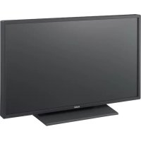
- When you install multiple equipment with the unit, the following problems, such as malfunction of the remote control, noisy picture, noisy sound, may occur depending on the position of the unit and other equipment. On repacking Do not throw away the carton and packing materials. They make an ideal container in which to transport the unit. When shipping the unit, repack it as illustrated on the carton. If you have any questions on this unit, contact your authorized Sony dealers. On the illustrations The illustrations of the display in the Operating Instructions are of the FWD-46B2. Introduction7
Recommendations on Installation Provide an ample amount of space around the display
- To prevent internal heat buildup from sealing off the display, make sure to ensure proper ventilation by leaving open the minimum amount of space around the display, as illustrated below.• The ambient temperature must be 0 °C to 40 °C (32 °F to
°F). Be careful when installing the display near a ceiling. The temperature there can become much higher than the normal, lower-level room temperature.• When using the stand, you use the applicable Tabletop Stand SU-S02 (not supplied).For the fitting method, see the installation manual of the Tabletop Stand.• Consult with Sony qualified personnel for wall mount installation.• Regarding the installation of hardware such as brackets, screws, or bolts, we cannot specify the products. Actual installation is up to the authorized local dealers. Consult with qualified Sony personnel for installation.• While the display is on, a certain amount of heat builds up inside. This can cause burns. Avoid touching the top or rear of the display when it is powered on or just after it has entered standby mode. When using the Tabletop Stand Front Side Units: cm (inches)25 (9 /8) (4)
10 (4)When moving or installing the display when it is attached to the tabletop stand (not supplied), do so with at least 2 people. Note9
When mounting the display horizontally When mounting the display vertically Front Side 25 (9
Front Side Make sure that the (POWER) switch is at the lower left. 20 (7
Front Location and Function of Parts and Controls Parts Description 1 1 (Power/Standby) indicator
- Lights up in green when the display is switched on.
- Lights up in red when the display is in standby mode. Lights up in orange when the display enters the power saving mode while a signal is input from a PC. When the 1 indicator blinks in red, see page 37. When the “LED” option in the “Multi Display” settings is set to “Off” and the “Position” option is not set to the right-bottom, the indicator does not light up in green even when the display is turned on, except for the case of no signal or an unsupported signal. 2 Remote control sensor Remote control light receptor. Note11
Parts Description 1 Mounting bracket installation holes Screw holes conforming to VESA standard. Pitch: 200 mm × 200 mm (FWD-32B1) 400 mm × 400 mm (FWD-55B2/46B2/42B2) Use screws with the proper thread and length, and tighten to the proper torque. Diameter of thread: M6 Thread length: 10 mm Torque: 20 kgf·cm 2 Speaker installation holes (FWD-55B2/46B2/42B2) For attaching the speakers SS-SPG02 (not supplied). 2 Internal speakers (FWD-32B1) 3 Tabletop stand installation holes For attaching the tabletop stand SU-S02 (not supplied). 4 1 (POWER) button Switches the display on or off (standby). Operate when the main power switch is “ON” ( side). 5 INPUT/ (ENTER) button Press to select a signal to be input from the INPUT connector. The signal to be input switches as follows each time you press the INPUT button. Press to set your choice. 6 +/–/F/f (volume/menu item selection) button Press to control speaker volume. When the menu is displayed, press to select the menu item or set a value. Press to set your choice. 7 MENU/ (RETURN) button Press to show menus. This returns to the preceding menu screen. Note Video HD15 DVI HDMI13
8AC IN socket Connect the supplied AC power cord to this socket and to a wall outlet (page 20). Once you connect the AC power cord and turn on main power switch, the 1 indicator lights up in red and the display goes into the standby mode. 9 / (main power) switch Turn the main power switch to “ON”(press the side) when setting up the display. When the main power switch is turned “OFF” (press the side), the power consumption is 0W. 0 SPEAKER socket (FWD-55B2/46B2/42B2) Connect the speakers SS-SPG02 (not supplied) to this socket. For more details on connecting the speakers, see the operating manual that came with the speakers. For details on how to route the speaker cords, see page 21. qa AUDIO OUT (L/R) (RCA connector) This is the audio monitor output terminal for external devices. Outputs an audio of the signal currently indicated on the screen.
- Settings assigned in “Sound Mode” or “Speaker Out” will not be reflected.
- The noise reduction status set by the remote control is not reflected. qs VIDEO VIDEO IN (BNC): Connects to the video output of a piece of video equipment. VIDEO OUT (BNC): Connects to the video input of a piece of video equipment. Pictures input from VIDEO IN will be output. Output regardless of whether the power is on or off (including standby). AUDIO IN (Stereo mini jack): Connects to the audio output of a piece of video equipment. Parts Description Notes14
) IN: Connects to the component signal output of a piece of video equipment or PC. . AUDIO IN: Inputs an audio signal. Connects to the audio signal output of a piece of video equipment or PC. Use the same connector as in qs VIDEO qf HD15 (RGB/ COMPONENT) (D-sub 15-pin) HD15 (RGB/COMPONENT) IN: Connects to the analog RGB signal or component signal output of a piece of video equipment or PC (page 42). HD15 (RGB/COMPONENT) OUT: Connects to the analog RGB signal or component signal input of a piece of video equipment or PC (page 42). Signals input from the HD15 (RGB/COMPONENT) IN connector above will be output. AUDIO IN: Inputs an audio signal. Connects to the audio signal output of a piece of video equipment or PC.
- When the display is not connected to an AC power or is in the standby mode, no signal is output from the HD15 (RGB/COMPONENT) OUT.
- When inputting a component signal, be sure not to input sync signals to pins 13 and 14. If you do so, the picture may not be displayed properly. qg HDMI HDMI IN: HDMI (High-Definition Multimedia Interface) provides an interface between the display and any HDMI-equipped audio/video equipment, as well as PC. You can enjoy enhanced or high-definition video, and two-channel digital audio. The appropriate mode for a piece of audio/video equipment or PC is automatically selected in accordance with the connected equipment. Be sure to use only an HDMI cable (not supplied) that bears the HDMI logo. We recommend that you use a Sony HDMI cable (high speed type). Parts Description Notes Note HDMI, High-Definition Multimedia Interface, and the HDMI Logo are trademarks or registered trademarks of HDMI Licensing LLC in the United States and other countries.15
Parts Description qh DVI (DVI-D 24-pin) DVI IN: Connects to the digital signal output terminal of the video equipment or PC. Supports HDCP copy protection. AUDIO IN: Inputs an audio signal. Connects to the audio signal output of a piece of video equipment, etc. qj REMOTE (STRAIGHT) (D-sub 9-pin)
- This connector enables remote control of the display using the RS-232C protocol. For details, contact your authorized Sony dealer. When using this connector, select “RS-232C” in “Network Port”. (page 31) qk REMOTE ( ) (10BASE-T/100BASE-TX) Serves to connect the display to a network, using a 10BASE-T/100BASE-TX LAN cable. You can assign various settings and control the display via the network from a PC. For safety, do not connect the connector for peripheral device wiring that might have excessive voltage to this port. Follow the instructions for this port. When using this connector, select “LAN” in “Network Port”. (page 31) Note Caution Note16
Remote Control You cannot use the S VIDEO button, button, the OPTION1 button and the OPTION2 button on this display. Button Description
- The 5 button and button have a tactile dot. Use the tactile dot as a reference when operating the display.
- Insert two size AA (R6) batteries (supplied) by matching the 3 and # on the batteries to the diagram inside the remote control’s battery compartment. Danger of explosion if battery is incorrectly replaced. Replace only with the same or equivalent type recommended by the manufacturer. When you dispose of the battery, you must obey the law in the relative area or country. Note 1 ON (power-on) button Press to turn the display on. Operate when the main power switch on the rear of the display is “ON.” 2 DVI button Press to select the signal input to the DVI port. 3 HDMI button Press to select the signal input to the HDMI IN connector from a piece of video equipment. 4 VIDEO button Press to switch between the input signals from VIDEO IN and COMPONENT IN 5 PICTURE button Selects “Picture Mode”. Each press toggles between “Vivid”, “Standard”, “Custom”, and “Conference”. 6 F/f/G/g/ buttons Press the F/f/G/g buttons to move the selected menu item and set the values. Pressing sets the selected menu or setting items. 7 button Press to change the aspect ratio (page 18). 8 MENU button Press to show the menu on the screen. Press again to hide the menu (page 22). NotesCaution
Push and slide to open17
Installing batteries Two size AA (R6) batteries are supplied for Remote Control RM-FW002. To avoid risk of explosion, use size AA (R6) manganese or alkaline batteries. 9 ID MODE (ON/0-9/SET/C/OFF) buttons You can operate a specific display by entering the "Index Number" of that display without affecting other displays installed at the same time.
- ON button: Press to show the “Index Number” on the screen.
- 0-9 button: Press to enter the “Index Number” of the display you want to operate.
- SET button: Press to set the input “Index Number”.
- C button: Press to clear the input “Index Number”.
- OFF button: Press to return to the normal mode (page 19). 0 +/– button Adjusts the picture (contrast) level. qa +/– button Press to adjust the volume. qs button Press to mute the sound. Press again to restore sound. qd DISPLAY button Press to display the currently selected input, the type of the input signal and the “Aspect” setting on the screen. Press again to hide them. If this displayed information is left undisturbed for a short time, it will disappear automatically. qf HD15 button Press to select the input signal of the HD15 (RGB/COMPONENT) connector. The RGB signal or component signal is selected automatically or manually in accordance with the menu settings. qg STANDBY button Press to change the display to the standby mode.18
Useful buttons on the Remote Control Using the Wide Mode You can change the aspect ratio of the screen. Tip You can also access the “Aspect” settings in the “Screen” settings (page 27). For input from video equipment such as Video, DVD, etc. (other than PC input) 4:3 Original Source
For PC Input Illustrations below indicate the input resolution of 800×600 If the input resolution is higher than the panel resolution (1,920 × 1,080)*, the display of “Real” is the same as “Full 1”.
Using the ID MODE button You can operate a specific display by entering the "Index Number" of that display without affecting other displays installed at the same time. 1 Press ON button. Display’s “Index Number” appears in black characters on the lower left menu on the screen. (Every display is allocated an individual preset “Index Number” from 1 to 255.) 2 Input the “Index Number” of the display you want to operate using the 0 - 9 buttons on the remote control. The input number appears right next to the “Index Number” of each display. 3 Press SET button. The characters on the selected display change to green while the others change to red. You can operate the specified display indicated with green characters only. Only the operation of ON (power-on) button and STANDBY/ID MODE-OFF button is effective to other displays, as well. 4 When all of the setting changes have been completed, press OFF button. The display returns to the normal screen. To correct the Index Number Press the C button to clear the current input “Index Number”. Return to Step 2, and input a new “Index Number”. Tip To change the “Index Number” of the display, see “Index Number” in “Control Setting” on page 28. Index Number : 117 Index Number Index Number : 117
- First make sure that the power of each piece of equipment is turned off.• Use cables suitable for the equipment to be connected.• Connect the cables, fully inserting them into the connectors or jacks. A loose connection may cause hum and other noise.• To disconnect the cable, pull it out by grasping the plug. Never pull the cable itself.• See the instruction manual of the equipment to be connected, too.• Insert the plug securely into the AC IN socket.• Use one of the two AC plug holders (supplied) to securely hold the AC plug. Connecting the Speakers (FWD-55B2/ 46B2/42B2) Connect the speakers SS-SPG02 (not supplied). Please be sure to connect the speakers correctly. For more details on connecting the speakers, see the operating manual of the speakers. For details on how to route the speaker cords, see page 21. Connecting the AC Power Cord 1 Plug the AC power cord into the AC IN socket. Then, attach the AC plug holder (supplied) to the AC power cord. 2 Slide the AC plug holder over the cord until it connects to the AC IN socket cover. To remove the AC power cord Release the clips of the AC plug holder from the lock of the AC IN socket cover, then hold the plug and pull out the AC power cord. Connections AC IN socketAC power cord AC plug holder Lock Clip AC IN socket cover21
Cable Management Using the cable holders You can neatly bundle the cables with the cable holders (×6 FWD-32B1: ×3) provided. Attach the cable holders as shown in the illustrations below.
Overview of the Menus 1 Press MENU button. 2 Press F/f to highlight the desired menu icon. 3 Press or g. To exit the menu, press MENU button. To change the on-screen language Select the desired language for on-screen settings and messages from “English”, “Deutsch”, “Français”, “Español”, “Italiano” or “ ”. “English” (English) is set for the default setting (page 28). The settings provide you access to the following features:
- Menu icons displayed at the bottom of the screen may not work, depending on the settings. Using the Settings
Picture/Sound Settings For the setting method, see “Overview of the Menus” (page 22). *: Not selected during PC input. Menu Function and operation Picture Mode You can choose a picture quality to match your picture type and surrounding brightness. Tip To change from one “Picture Mode” option to another, you can also use PICTURE button (page 16) on the remote control instead. Vivid Enhances picture sharpness, and maximizes contrast. Standard Flat setting. Custom Adjusts in more detail. Conference Adjusts the picture quality for video conferencing under fluorescent lights. “Conference” may not be effective depending on the environment of use or your video conference system. In this case, adjust the picture using “Picture Mode Adjust.” (page 23), or switch to a “Picture Mode” setting other than “Conference”. Picture Mode Adjust You can adjust picture quality for each “Picture Mode” in more detail.
- “Backlight”, “Noise Reduction” and “CineMotion” settings are common for all “Picture Mode”.
- During PC input, you cannot adjust “Chroma”, “Phase”, “Sharpness”, “Noise Reduction” or “CineMotion”. Backlight Adjusts LCD screen brightness. Contrast Adjusts to increase or decrease contrast. Brightness Adjusts picture brightness. Chroma * Adjusts color intensity. Phase * Adjusts the color tones of the picture. “Phase” is available if the video signal's color system is NTSC. Sharpness * Adjusts to sharpen or soften the picture. Noise Reduction * Reduces noise from connected equipment. Higher settings are effective when there is a lot of noise. Off/Low/Mid/High CineMotion * Select “Auto” or “Off”. If you select “Auto”, it optimizes the screen display automatically by detecting picture content and applying a reverse 3-2 or 2-2 pull-down process. The picture will appear clearer and more natural.
- “CineMotion” may not be correctly processed depending on the input signal pattern.
- The setting of “CineMotion” is invalid when displaying 1080/50i, 1080/60i or 1080/ 24psf signal with “Aspect” set to “Wide Zoom” or “Zoom”. Note Notes Note Notes24
Picture Mode Adjust Dynamic Picture Select “On” or “Off”. Select “On” to enhance contrast by making white brighter and black darker. You cannot set “Dynamic Picture” when “Picture Mode” is set to “Conference”. Gamma Correct. Balances the light and dark portions of pictures. Higher settings have larger gamma correction. You cannot set “Gamma Correct.” when “Picture Mode” is set to “Conference”. High/Mid/Low/ Color Temp. White tone can be adjusted to suit your preference. Default settings are set when shipped from factory. Tip Restores the default settings by selecting “Reset” on the tone adjusting screen. Cool Gives white colors a blue tint. Neutral Gives white colors a neutral tint. Warm Gives white colors a red tint. Custom Enables a broader range of white tone to be set than above. Brightness Boost Select “On” or “Off”. If you select “On”, then the picture quality is adjusted to emphasize brightness.
- You can set “Brightness Boost” when “Picture Mode” is set to “Vivid”.
- When “Brightness Boost” is set to “On”, you cannot adjust the “Backlight”, “Contrast”, “Brightness” or “Color Temp.” settings.
- When “Brightness Boost” is set to “On”, with “Backlight” set to “Max” and “ECO Mode” set to “Off”, the brightness is at its maximum. Reset Select “Cancel” or “OK”. If you select “OK”, it resets all settings of “Picture Mode Adjust” to default settings. Menu Function and operation Note Note Notes25
Sound Mode You can adjust the sound output from the speakers SS-SPG02 (not supplied) with various “Sound Mode” settings. For FWD-32B1, you can adjust the sound output from the internal speakers. Dynamic Enhances treble and bass. Standard Flat setting. Custom For more detailed adjustment. Sound Mode Adjust. You can adjust sound tone in detail. Tip You can set “Treble” and “Bass” when the “Sound Mode” is set to “Custom”. Treble Adjusts to increase or decrease treble. Bass Adjusts to increase or decrease base. Balance Adjusts left/right speaker balance. Surround Select the surround mode according to the type of picture. Off No surround output. Hall When you want to get an even richer stereo sound from movies or music programs. Simul. When you want to get a richer sound from ordinary monaural programs or news telecasts by using simulated stereo sound. Reset Select “Cancel” or “OK”. If you select “OK”, it resets all settings of “Sound Mode Adjust.” to default settings. Menu Function and operation26
Screen Settings For the setting method, see “Overview of the Menus” (page 22). If no signal is being input, “Aspect” and “Adjust Screen” cannot be set. Note Menu Function and operation Multi Display Allows you to make settings for connecting multiple displays to form a video wall.
- During video input, “Multi Display” displays a picture as close as possible to the current “Aspect” setting. But during PC input, it displays with “Aspect” set to “Full 2”.
- When “Position” is set to the right-bottom, the 1 indicator lights up even if “LED” is set to “Off”. The indicator also lights up even when the display is off (standby), errors are detected, or the display is in sleep mode including the case of no signal or unsupported signal.
- “Multi Display” function cannot be used for 480i, 576i,1080/50i, 1080/60i or 1080/ 24psf signal. Multi Display Do settings to form a video wall. Off Uses a single screen. 2×2 3×3 4×4 Settings to connect 2, 3 or 4 displays both vertically and horizontally. 1×2 1×3 1×4 Settings to connect 2, 3 or 4 displays horizontally. 2×1 3×1 4×1 Settings to connect 2, 3 or 4 displays vertically. Position Settings for the screen position of each display. Output Format You can select a picture output format. The picture position is automatically adjusted, and you can get a suitable picture output. Tiles Shows full signal on each screen. Window Shows one large picture with multi display naturally. Part of the signal will go behind the bezel area. LED Select “On” or “Off”. If you select “On”, the 1 indicator on the front panel (page 10) to be continually turned on. Notes27
- Not selected during PC input. ** Selected during PC input. Menu Function and operation Aspect Change the screen’s aspect ratio. For details, see page 18. Tips
- To change from one “Aspect” option to another, you can also use button on the remote control.
- Select “Zoom” to display movies and other DVD content with black bands, using the entire viewable area of the screen for video input. You cannot set “Aspect” while using the “Multi Display” function. Wide Zoom * Enlarges to fill screen with minimum distortion. Zoom * Enlarges the picture, keeping the same aspect ratio. Full * Enlarges the picture horizontally to fill the screen when the picture source is 4:3 (Standard definition). When the picture source is 16:9 (High definition), it displays in the same 16:9 aspect ratio. 4:3 * Displays all picture source in 4:3 aspect ratio. Full 1 ** Enlarges the picture to fill the screen in the vertical direction, keeping the same aspect ratio. A black frame may appear around the picture. Full 2 ** Enlarges the picture to fill the screen. Real ** Displays the picture in its original number of dots. If the input resolution is higher than the panel resolution (1,920 × 1,080, FWD-32B1: 1366 × 768), the display of “Real” is the same as “Full 1”. Adjust Screen Adjust screen size and position. “Auto Adjustment”, “Phase” and “Pitch” are not available when the PC signal is digitally input using a DVI IN or HDMI IN connector. Auto Adjustment ** Select “Cancel” or “OK”. If you select “OK”, the display automatically adjusts the position and phase of the picture when it receives an input signal from the connected PC. Note that “Auto Adjustment” may not work well with certain input signals. In such cases, manually adjust the options below. To adjust correctly, adjust while the entire screen displays a bright picture. Phase ** Adjusts the phase when the screen flickers. Pitch ** Adjusts the pitch when the picture has unwanted vertical stripes. H Size Adjusts the size of the picture horizontally. H Shift Adjusts the picture position left and right. V Size Adjusts the picture size vertically. V Shift Adjusts the picture position up/down. Reset Select “Cancel” or “OK”. Select “OK” to reset all settings of “Adjust Screen” to default settings. Note Note Note Note28
Setup Settings For the setting method, see the section of “Overview of the Menus” (page 22). Menu Function and operation Language Select from the language settings shown. Select “English”, “Deutsch”, “Français”, “Español”, “Italiano” or “ ”. Timer Setting You can adjust time, display the built-in clock, or set the timer to make the display power on/off at a predetermined time. If the main power switch is left turned off or the AC power cord removed for a long time, the built-in clock may lose or gain time significantly. In this case, reset the clock to the right time. Clock Set Sets the day of the week and the hour of the day. Date Set Sets the date (year, month, date). The day is automatically set. Time Set Sets the time. Clock Display Select “On” or “Off”. If you select “On”, when the remote control’s DISPLAY button is pressed, it shows the current time which was set. On/Off Timer Sets the day of the week and the hour of the day. This cannot be used unless the “Timer Setting” has been set. ECO Mode Reduces power consumption by changing the brightness of the backlight. Selecting “High” reduces power consumption more than “Low”. Off/Low/High Status Display Select “On” or “Off”. If you select “On”, the input signal and “Aspect” setting information show on the screen for about 5 seconds when the display is turned on. When you switch the input signal, the input signal information shows for about 5 seconds. Tip You can display the input signal and “Aspect” setting information by pressing DISPLAY button on the remote control. Speaker Out Select “On” or “Off”. If you select “On”, sound is output from the speakers. Advanced Setup Enter more detailed settings. Control Setting This menu is used for settings of operation of the display and the remote control. Index Number You can change the index number of the display if necessary. Select to set the index number of the display with F/f buttons on the display, and press button to confirm the setting. The “Index Number” cannot be set with the remote control. Note Note Note29
Advanced Setup Control Mode Set to control the display from the remote control or from the display. When this item is operated, the available modes will differ depending on whether you select by the remote control or the display. When setting this item with button on the remote control, you can select only “Display+Remote” or “Remote Only”. When setting this item with button on the display, you can select only “Display+Remote” or “Display Only”. Display+Remote Enables operation of the display with the control buttons on the display and the remote control. Display Only Enables operation of the display with the control buttons on the display. You can only use buttons on the display to enter this setting. Remote Only Enables operation of the display with the remote control. You can only use the remote control to enter this setting. Auto Screen Adjust Select “On” or “Off”. If you select “On”, it saves settings such as picture size and position for each input signal, and the last settings are automatically applied. The “Auto Screen Adjust” function only works during RGB input. Auto Shut Off Select “On” or “Off”. When “On” is selected, the display automatically goes into standby mode or power saving mode if no signal is input from the DVI, the HDMI, the HD15 (RGB/COMPONENT) or the COMPONENT input connectors for about 30 seconds. If no signal is input from the VIDEO connector for about 5 minutes, the display automatically goes into standby mode. Tips
- This function is available when “Screen Saver” is set to “Off”.
- If “DPMS” is set to “On”, you can select the settings for activating the power saving mode. DPMS Select “On” or “Off”. When “On” is selected, the display automatically goes into power saving mode if no signal is input from the DVI, the HDMI or the HD15 (RGB) input connectors for about 30 seconds. When “Off” is selected, the display automatically goes into standby mode if no signal is input from the DVI, the HDMI or the HD15 (RGB) input connectors for about 30 seconds. Tips
- While in the standby mode, press the 1 button on the display or the ON button on the remote control to turn the display on. In the power saving mode, the display is turned on automatically when a signal is input.
- This function is available when “Screen Saver” is set to “Off”.
- This function is available when “Auto Shut Off” is set to “On”. Overscan Selects whether to display images with overscan or justscan. Auto Automatically determines whether it is a DTV signal, then overscans and displays the image.
Displays image with overscan. Off Displays image with justscan. During DTV signal input, it may display a screen like when a PC signal is input. Example: 480P → 720 × 480/60 Menu Function and operation Note Note Note30
Advanced Setup Sync Mode Set the type of signal input at pin 13 of the HD15 (RGB/COMPONENT) IN connector.
- “Sync Mode” is available only when analog RGB signal is input to HD15 connector.
- There are some inputs for which only “H/Comp” can be selected. In this case, input horizontal/vertical synchronization signals through the pin 13 or 14 of the connectors.
- This display does not support the three value sync format of 576/60p.
- When “Video” is selected in “Sync Mode”, you can only set the 575/50i and 480/ 60i signals. H/Comp Sets a horizontal synchronous signal input. Video Sets a video signal input. RGB/YUV Sets the type of signal for a piece of video equipment or PC connected to the HD15 (RGB/COMPONENT) connector of the display. Auto Automatically sets whether an analog RGB signal or a component signal is input from a connected device. RGB Set when an analog RGB signal is input from a connected device. YUV Set when a component signal is input from a connected device. Color System Select “NTSC” or “PAL” to set the color system. Select “Auto” to set the color system automatically. “Color System” is available when the input signal is from a VIDEO IN connector (Composite video signal). RGB Signal Set whether a 1280 × 720/60, 720 × 480/60 or 1920 × 1080/60 RGB input signal is displayed as a PC signal or a video signal. Select “HD15”, “DVI” or “HDMI” according to the input connector, and then select “PC” or “Video” for each. The following input connectors are valid for each setting “HD15”, “DVI” or “HDMI”. “HD15”: HD15 (RGB/COMPONENT) IN connector “DVI”: DVI IN connector “HDMI”: HDMI IN connector
Screen Saver This is a setting to prevent or reduce screen burn or after-image that can occur by long periods of screen display of the same image. Off Disables the “Screen Saver” setting. All White Displays an all-white screen. (Stops automatically after about 30 minutes and the display enters standby mode.) Sweep Scrolls a white bar over the screen. Standby Turns on a screensaver for the time set in “Timer Setting” in standby (page 10). (The display is blank during screensaver operation.) When the set time has passed, the display returns to the regular standby state. Menu Position (FWD-55B2/46B2/42B2) Changes the menu screen's orientation to match the display's installation orientation. Landscape Show the menu screen horizontally. Portrait Show the menu screen vertically. Menu Function and operation Notes Note31
Advanced Setup Network Port Sets which terminal connects to the PC when the display is remote controlled by the PC.
- You cannot use REMOTE (STRAIGHT) and REMOTE ( ) simultaneously.
- Select “LAN” when performing “IP Address Setup” or “Speed Setup”. RS-232C Select when connecting the display and PC via the REMOTE (STRAIGHT) connector. LAN Select when connecting the display and PC via the REMOTE ( ) connector. IP Address Setup Sets an IP address to enable communication between the REMOTE ( ) connector of the display and a device such as a PC connected with a LAN cable. For details on how to make the settings, see the section of “Preparations for Using the Network Functions” (page 32). Speed Setup Sets a communication speed between the REMOTE ( ) connector of the display and a device such as a PC connected with a LAN cable. For details on how to make the settings, see the section of “Preparations for Using the Network Functions” (page 32). Power On Delay Adjusts the time from when the display is switched on until it actually turns on. Sets to “Off”, and 1 to 120 seconds. This suppresses a sudden load fluctuation to the power equipment when multiple units are connected. HDMI Control If you connect HDMI control compatible equipment to the HDMI input connector of the display, then the equipment can be controlled together. You should use the remote control to switch on/off the display and connected equipment. HDMI Control Select “On” or “Off”. If you select “On”, then HDMI equipment control works, and it can be set to “Auto Device Off” and “Auto Display On”.
- If it does not work, also set HDMI settings on the connected equipment.
- To control it, the connected equipment must be HDMI control compatible, and it must be set to enable HDMI equipment control.
- Depending on the HDMI equipment, this may not operate together with this device in some cases. Auto Device Off Select “On” or “Off”. If you select “On”, then when the display’s power is switched off, the connected HDMI equipment’s power is also switched off together. Auto Display On Select “On” or “Off”. If you select “On”, then when connected HDMI equipment play or other control is selected, the display’s power also turns on together. Information Displays the “Date”, “Model Name”, “Serial Number”, “Operation Time”, “Software Version” and “IP Address” of your display. All Reset Select “Cancel” or “OK”. If you select “OK”, then all adjustments and settings reset to defaults. The items included in the “Information” option and the “Index Number” will not be reset. Menu Function and operation Notes Note Notes Note32
Preparations for Using the Network Functions Precautions
- The software specifications of this display are subject to change for improvements without notice.
- Screens shown by application software may differ slightly from the illustrations shown in this manual.
- For safety, connect the port of this display only to a network where there is no danger of excessive voltage or voltage surges.
- The steps described in this manual are guaranteed only for use under the following environment conditions. Operating system: Microsoft Windows XP/Windows Vista/ Windows 7 Browser: Microsoft Internet Explorer 7.0 or later
- To ensure security on the network, setting a user name and password is recommended. For information on how to make these settings, see the section “Setup screen” (page 35). For security settings, refer to your network administrator. Setting an IP address The display can be connected to a network with 10BASE-T/100BASE-TX LAN cable. When connected to a LAN, the IP addresses of the display can be set using one of the following two methods. Consult your network administrator regarding details about IP address selection.
- Assigning a fixed IP address to the display Normally this method should be used. Note that in default setting, the display is set to obtain an IP address automatically.
- Automatically obtaining an IP address If the network to which the display is connected has a DHCP server, you can have the DHCP server automatically assign an IP address. Note that in this case the IP address may change every time the display in which the display is installed is turned on. Before setting the IP address, connect the LAN cable to the display to establish the network. After about 30 seconds, turn on the display, and then start making the desired settings. Network Functions
- Microsoft and Windows are registered trademarks of Microsoft Corporation in the United States of America and/ or other countries.
- All other product names, company names, etc. mentioned in this manual are trademarks or registered trademarks of their respective owners.33
Assigning a fixed IP address to the display 1 Press MENU to bring up the main menu. 2 Select “Setup” with F/f and press . 3 Select “Advanced Setup” with F/f and press . 4 Select “IP Address Setup” with F/f and press . 5 Select “Manual” with F/f and press . 6 Select an desired item to set from “IP Address”, “Subnet Mask”, “Default Gateway”, “Primary DNS”, “Secondary DNS” with F/f and press . 7 Set the three digit value (0 to 255) for each of the four box with F/f on the display or numeric keys on the remote control and press or g. 8 Set the three digit value (0 to 255) for each of the four boxes and press . Repeat the same procedure as step 6 and select the next desired item to set with F/f and press
9 After values are set for all the desired items, select “Execute” with F/f, then press . Select “Execute” and press . An IP address is set manually. Automatically obtaining an IP address 1 Press MENU to bring up the main menu. 2 Select “Setup” with F/f and press . 3 Select “Advanced Setup” with F/f and press . 4 Select “IP Address Setup” with F/f and press . 5 Select “DHCP” with F/f and press . Select “Execute” and press . An IP address is automatically set. When “Cancel” is selected, the setting will not be executed. When an IP address is not set properly, the following error codes will be displayed in accordance with the error cause.Error 1: Communication errorError 2: The specified IP address is already used for other equipmentError 3: IP address errorError 4: Gateway address errorError 5: Primary DNS address errorError 6: Secondary DNS address errorError 7: Subnet mask error Checking the automatically assigned IP address 1 Press MENU to bring up the main menu. 2 Select “Setup” with F/f and press . 3 Select “Information” with F/f and press
4 Select “IP Address” with F/f and press
The IP address currently acquired is displayed. Tip When an IP address cannot be acquired properly, the previously acquired IP address is shown in “Information” and in “Manual” of “IP Address Setup”. Setting a communication speed 1 Press MENU to bring up the main menu. 2 Select “Setup” with F/f and press . 3 Select “Advanced Setup” with F/f and press . 4 Select “Speed Setup” with F/f and press
5 Select a desired communication speed to set from “Auto”, “10Mbps Half”, “10Mbps Full”, “100Mbps Half”, or “100Mbps Full” with F/f and press . When “Auto” is selected, a communication speed appropriate for your network configuration is automatically set. 6 Select “Execute” with F/f and press to reflect the setting. Note34
PC Operation Controlling the display You can make various display settings on the screen of the PC.Make sure that the display, PC, and router or hub are properly connected with the network cable. Then turn on power to the display, the PC, and the router or hub.There are four display screens, divided by function: Information screen, Configure screen, Control screen, and Setup screen.For details on the functions of buttons, see instructions for each function of the display. 1 Start the browser of the PC (Internet Explorer 7.0 or later). 2 Enter the IP address that was assigned to the display in the previous page as “http://xxx.xxx.xxx.xxx”, then press the ENTER key on the keyboard. When a user name and password have been set, the “Network Password” screen appears. Enter the user name and password that were set, and then proceed to the next step. 3 Click the function tab at the top of the screen and select the desired screen. Setting items on respective screens When using the LAN function of the display Information screen This screen shows the model name, serial number and other display information, as well as the power status and the input signal selection.The screen is for information only. There are no items that can be set. Configure screen TimerLets you make settings for the timer function.Click “Apply” when done.Screen SaverLets you make settings for the screensaver function.Click “Apply” when done.Before setting the “Timer” function, make sure to configure the time setting on the Setup screen (page 35). Control screen POWERSwitches the display on or off.INPUTLets you select the input signal.PICTURE MODELets you select the picture mode.ASPECTLets you switch the aspect ratio of the image.Contrast +/– buttonsAdjust the screen contrast.Brightness +/– buttonsAdjust the picture brightness.Chroma +/– buttonsAdjust the color intensity. Note35
Phase +/– buttons Adjust the color balance. Reset button Resets the settings from “Contrast” to “Phase” to their factory default values.
- If the input signal is Video and the color system of the video signal is not NTSC, “Phase” is not available.
- “Chroma” and “Phase” are not available for PC input.
- “Normal” at the ASPECT setting corresponds to “4:3” for video input or “Real” for PC input. Setup screen This screen lets you set up the Network Password. The factory default settings are as follows: Name: root Password: pudadm After you have made any changes or entered information, click “Apply” at the bottom of each screen to enable the settings. Special characters cannot be used in the text fields. Owner Information Owner Enter owner information here. Display Location Enter information about the display installation location here. Do not use spaces when entering the information. Doing so may cause the file name to display incorrectly. Memo You can enter auxiliary information here. Time Time Enter the time, day of the week, year, month, and day. Network Internet Protocol (TCP/IP) Select “Specify an IP address” to enter each value in the IP address’s numeric string. Select “Obtain an IP address (DHCP)” to acquire an IP address automatically from the DHCP server. Note that in this case the IP address may change every time the display in which the display is installed is turned on. The IP address can be set from the menu of the display. For details, see “IP Address Setup” (page 31). Password The administrator and user name and password information can be entered here. The administrator name is fixed to “root”. Each can be a maximum of 8 characters long. Once a user name and password are set, the “Network Password” screen appears whenever the display control screen of the display is called up. To ensure security on the network, setting a user name and password is recommended. Mail Report Error Report When a display function error has occurred, an error report is immediately sent by e-mail (error notification). Status Report The status of the display can be reported via email according to the selected time interval. Address Enter the target e-mail address here. Up to four addresses can be specified, for simultaneous sending of an error report. The maximum length for each address is 64 characters. Mail Account Mail Address: Enter the allocated mail address here. The maximum length for the address is 64 characters. Outgoing Mail Server (SMTP): Enter the mail server address here. The maximum length for the address is 64 characters. Requires the use of POP Authentication before Send e-mail (POP before SMTP): If POP authentication is required when connecting to the SMTP server, select this check box. Incoming Mail Server (POP3): When POP authentication is used for the “POP before SMTP” setting, enter the POP3 server address here. Account Name: Enter the mail account name here. Password: Enter the mail password here. Send Test Mail: To test whether mail can be sent successfully to the specified address(es), select this check box and click “Apply”. A test mail will be sent. Notes Note Note36
If any of the following items is not set or not set correctly, an error message appears, and test mail cannot be sent:
- Mail account address and mail server address (SMTP) Advanced Gives access to advanced settings to enable use of various applications on the network. Make the settings as required by the respective application. Advertisement Lets you make settings for the Advertisement and Broadcast functions on the network. ID Talk Lets you make settings for the ID Talk function. ID Talk is a protocol that allows network-based control of the display. Controlled items includes various settings and adjustments such as color temperature and gamma. For information about supported ID Talk commands, contact your local Sony dealer. SNMP The display is a network equipment which supports SNMP (Simple Network Management Protocol). Besides standard MIB-II, Sony Enterprise MIB is also supported. This screen allows making settings for SNMP. For information about supported SNMP commands, contact your local Sony dealer. Returning to default settings To reset all settings made on the “Setup” screen to the factory default condition, reset to the default settings by assigning the “All Reset” setting, and then assign the appropriate settings of the network again. Note37
Troubleshooting Check whether the 1 indicator is flashing red. When it is flashing The self-diagnosis function is activated. 1 Check how many times the 1 indicator flashes and how long it stops flashing. For example, the indicator flashes 2 times, stops flashing for 3 seconds, and flashes 2 times. 2 Press 1 (POWER) switch on the display and the main power switch to switch off the power, then disconnect the power cord. Inform your dealer or Sony service center of how the indicator flashes (the number of flashes and the duration of light out). When it is not flashing 1 Check the items in the table below. 2 If the problem still persists, have your display serviced by qualified personnel. Other Information Problem Possible Remedies The power switch and control buttons on the display do not work.
- Check the settings of “Control Setting” (page 28). The power will not come on even if the 1 (POWER) switch is turned ON, or the ON (power-on) button on the remote control is turned ON.
- Check that the main power switch is not turned “OFF” (page 13). No video signal is output from the
- There is no HD15 (RGB/COMPONENT) OUT output when this device is in standby status or the AC power supply is switched off. No picture. No picture.
- Check the connection between the video equipment and the display.
- Check if the “Auto Shut Off” function is set to “On” (page 29).
- Check if the room temperature is not more than 40°C. The display turns on or off automatically.
- Check the “HDMI Control” settings (page 31). Poor picture. No color/Dark picture/The picture is too bright/Color is not correct/The picture gradually becomes dark/Horizontal noise appears on the picture
- Press PICTURE to select the desired “Picture Mode” (page 16).
- Adjust the “Picture Mode Adjust.” options in the “Picture/Sound” settings (pages 23, 24).
- Check the condition of the signal cable.
- Check if the room temperature is not more than 40°C.
- Check the settings in “ECO Mode” (page 28). The whole screen is tinged green or purple.
No sound/Noisy sound. Picture displayed, no sound.
- Check the volume control.
- Press on the remote control or + so that “Muting” disappears from the screen (page 17).
- Check the setting of “Speaker Out” (page 28). Remote control does not operate.
- Check the polarity of the batteries or replace the batteries.
- Point the remote control at the remote control sensor of the display.
- Keep the remote control sensor area clear from obstacles.
- Check the settings of “Control Setting” (page 28).
- Fluorescent lamps can interfere with remote control operation; try turning off the fluorescent lamps. Cannot connect to the network.
- Plug the cable firmly into the REMOTE connector.
- Check the network settings of the PC.
- Reset to the default settings by assigning the “All Reset” setting on the “Setup” setting menu, and then assign the appropriate settings of the network again.
- Check the settings of “Network Port” (page 31). The display control screen (the Web screen displaying the display’s GUI) does not appear.
- Click the refresh or reload button on your Web browser.
- Make sure the IP address is correct.
Input Signal Reference Chart TV/Video signals a) VGA is a registered trademark of International Business Machines Corporation, U.S.A. b) Macintosh is a trademark of Apple Inc., registered in the U.S. and other countries. c) VESA is a registered trademark of the Video Electronics Standards Association. d) VESA Coordinated Video Timing
- For HDTV signals, input the tri-level sync signal to the 2nd pin of HD15 (RGB/COMPONENT) IN connector.
- If colors appear too light after input of a DVD signal to the display, adjust “Chroma” in the “Picture/Sound” settings.
- When the phase is readjusted, the resolution will be reduced.
- The signals from the Macintosh computer will not be guaranteed for recognizing the digital RGB input.
- You cannot input the signal indicated with * to DVI IN.
- Composite synchronous signals correspond to no.2, 4, 5, 7, 12, 13 and 14 in the signal table shown in the left.
- Video signals without color burst signal are not guaranteed. PC signals Resolution horizontal frequency (kHz) vertical frequency (Hz) 1VGA
480 / 60 (e.g.) The selected input signal is a PC signal. 480 / 60I (e.g.) The selected input signal is component video. NTSC (e.g.) The selected input signal is video signal. Not Supported Signal The selected input signal is non-supported signal. No Signal There is no input signal. Component The selected input signal is component video. HD15 The selected input is HD15. “RGB/YUV” is set to “Auto”. HD15 RGB The selected input is HD15. “RGB/YUV” is set to “RGB”. HD15 Component The selected input is HD15. “RGB/YUV” is set to “YUV”. DVI The selected input signal is DVI. HDMI The selected input signal is HDMI. Video The Composite Video signal is selected.41
-inch (diagonal 1,387.8315 mm) FWD-46B2: 46-inch (diagonal 1,168.1 mm) FWD-42B2: 42
COMPONENT COMPONENT (Y P
(DVI Specification Rev. 1.0 compliant) AUDIO IN Stereo minijack (× 1) 500 mVrms, high impedance
7W + 7W *Same as for COMPONENT General Power requirements 100 V to 240 V AC, 50/60 Hz, FWD-32B1: 1.1 A (Maximum) FWD-55B2: 1.5 A (Maximum) FWD-46B2: 1.3 A (Maximum) FWD-42B2: 1.4 A (Maximum) Power consumption FWD-32B1: 110 W (Maximum) FWD-55B2: 150 W (Maximum) FWD-46B2: 130 W (Maximum) FWD-42B2: 135 W (Maximum)
0.5 W (maximum in standby mode)
Operating conditions Temperature: 0 °C to 40 °C (32 °F to 104 °F) Humidity: 20% to 90% (no condensation) Storing/transporting conditions Temperature: -10 °C to +40 °C (14 °F to 104 °F) Humidity: 20% to 90% (no condensation)42
in.) (including optional stands) (w/h/d, excluding projections) FWD-55B2 1,245 mm × 715.8 mm × 84 mm (49
in.) (including optional stands) (w/h/d, excluding projections) FWD-46B2 1,053.6 mm × 608.2 mm × 84 mm (41
in.) 1,053.6 mm × 656.3 mm × 292.6 mm (41
in.) (including optional stands) (w/h/d, excluding projections) FWD-42B2
in.) (including optional stands) (w/h/d, excluding projections) Mass FWD-32B1 Approx. 13.4 kg (29.5 lb.) Approx. 15.2 kg (33.5 lb.) (including optional stands) FWD-55B2 Approx. 29.5 kg (65 lb.) Approx. 31.3 kg (69 lb.) (including optional stands) FWD-46B2 Approx. 22.4 kg (49.4 lb.) Approx. 24.2 kg (53.4 lb.) (including optional stands) FWD-42B2 Approx. 20.2 kg (44.5 lb.) Approx. 22 kg (48.5 lb.) (including optional stands) Supplied accessories AC power cord (1) AC plug holder (2) Cable holder FWD-32B1 (3) FWD-55B2/46B2/42B2 (6) Remote Control RM-FW002 (1) Size AA (R6) manganese batteries (2) Operating instructions (1) Optional accessories Display stand SU-S02 Speakers SS-SPG02 (except FWD- 32B1) Safety regulations UL 60950-1, CSA No. 60950-1-03 (c- UL), FCC Class B, IC Class B, EN 60950-1 (NEMKO), CE, C-Tick Design and specifications are subject to change without notice. Pin assignment HD15 RGB/COMPONENT connector (D-sub 15-pin) When inputting a component signal, be sure not to input sync signals to pins 13 and 14. If you do so, the picture may not be displayed properly. Pin No. Signal 1 Red video or C
4Ground 5Ground 6 Red ground 7 Green ground 8 Blue ground 9 Not used 10 Ground 11 Ground 12 SDA 13 H sync, Composite sync or Composite Video (as sync signal) 14 V sync 15 SCL Note43
AC IN socket 13, 20 Address 35 Adjust Screen 22, 27 Advanced 36 Advanced Setup 22, 28 Advertisement 36 All Reset 22, 31 Aspect 18, 22, 27 AUDIO IN connector 13, 14, 15 AUDIO OUT connector 13 Auto Adjustment 27 Auto Device Off 31 Auto Display On 31 Auto Screen Adjust 29 Auto Shut Off 29
Backlight 23 Balance 25 Bass 25 Brightness 23 Brightness Boost 24
COMPONENT COMPONENT (Y P
1600 × 1200@60 Hz (VESA STD)* 75,0 60
COMPONENT COMPONENT (Y P
COMPONENT COMPONENT (Y P
Not Supported Signal
COMPONENT COMPONENT (Y P
Backlight 21 Balance 23 Bass 23 Brightness 21 Brightness Boost 22
返回按钮 10 Full 16, 25 Full 1 16, 25 Full 2 16, 25