
42LM5WPTC - Monitor SANYO - Free user manual and instructions
Find the device manual for free 42LM5WPTC SANYO in PDF.

| Product Type | Liquid Crystal Display (LCD) Monitor |
| Brand | Sanyo |
| Model | 42LM5WPTC |
| Screen Size (Diagonal) | 42 inches (107 cm) |
| Resolution | 1366 x 768 (WXGA) |
| Display Format | 16:9 |
| Contrast Ratio | 1500:1 |
| Viewing Angle | Horizontal: 178°, Vertical: 178° |
| Power Supply | 100~240 V AC, 50/60 Hz |
| Power Consumption (Estimated) | Approx. 150 W |
| Weight (Estimated) | 18 kg |
| Dimensions (W x H x D, Estimated) | 99 x 58 x 10 cm (without stand) |
| Protection Standard | IP66 (dust and water jet resistant) |
| Color System | PAL / SECAM / NTSC 3.58 |
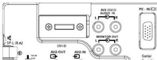
| Video Inputs | AV1 (SCART), AV2 (BNC: RGB H/V or Y Pb Pr), AV3 (composite), DVI-D, PC (mini D-SUB 15) |
| Audio Output | 2 x 6 W (built-in speakers), line out RCA |
| RS232C Serial Port | Input / Output for external control |
| Child Lock | Yes (disables local keys) |
| Winter Mode | Activates internal heater for temperatures < 4°C |
| Care and Cleaning | Unplug the device, use a damp cloth; do not apply liquid directly to the screen |
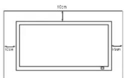
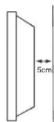
| Safety | Do not overload outlets, do not expose to open flames, provide ventilation space (5 cm rear, 10 cm sides/top) |
| Repairability | Do not open the back cover; contact an authorized technician for any repair |
| General Information | Manual available in multiple languages; remote control included with AA batteries |
Frequently Asked Questions - 42LM5WPTC SANYO
User questions about 42LM5WPTC SANYO
0 question about this device. Answer the ones you know or ask your own.
Ask a new question about this device
Download the instructions for your Monitor in PDF format for free! Find your manual 42LM5WPTC - SANYO and take your electronic device back in hand. On this page are published all the documents necessary for the use of your device. 42LM5WPTC by SANYO.
USER MANUAL 42LM5WPTC SANYO
Please read this Instruction book before using your LCD monitor. We wish you many hours of pleasure from your new LCD monitor
CAUTION: Please read and retain for your safety. This unit has been engineered and manufactured to assure your personal safety, but improper use can result in potential electric shock or fire hazards. In order not to defeat the safeguards incorporated in this monitor observe the following basic rules for its installation, use and servicing.
Installation and Use
Do not allow anything to rest on the power cord. Do not locate this LCD monitor where the cord will be damaged by people walking on it.
Do not overload wall outlets and extension cords as this can result in fire or electric shock.
A suitable socket outlet must be provided and shall be easily accessible.
Do not place this LCD monitor near any heat sources such as radiators, heaters, stoves and other heat-generating products (including amplifiers).
Do not place your LCD monitor on an unstable stand, shelf or table. Serious injury to an individual, and damage to the LCD monitor may result if it should fall. Your sales person can recommend approved wall mounting kit. A special wall mounting kit is available for this model.
This LCD monitor should be operated only from the type of power source indicated on the monitor or as indicated in the Operating Instructions. If you are not sure of the type of power supply, consult your sales person or your local power company.
For added protection it is strongly recommended that this LCD monitor is supplied via an approved earth fault protection device.
WARNING: To prevent injury the LCD monitor must be securely attached to the wall in accordance with the manufacturers installation instructions.
IMPORTANT:
This product must be earthed
This unit is not disconnected from the mains unless the mains lead is unplugged. The installer must make sure that the waterproof inline coupler is easily accessible.
This monitor is tested to IP66 standard rating.
This monitor is not protected against temporary or continuous immersion in liquid.
Do not use immediately after moving the LCD monitor from a low temperature to a high temperature environment, as this causes condensation, which may result in fire, electric shock, or other hazards. Before cleaning, unplug the monitor from the wall socket.
Do not mount near an open flame source. Open flames must never be used near this LCD monitor.
This LCD monitor should not be built in or enclosed in any way, heat build up will reduce the life of the monitor.
This LCD monitor should have a minimum distance of 5cm away from the wall and the monitor should have 10cm distance around the top and sides.
Always mount using recommended and substantial fixtures and fittings.
The rear finned section around the cabinet functions as a heat sink, removing heat away from the monitor. The external surface of the cabinet (finned area) must not be covered or the airflow restricted in anyway by enclosing the LCD monitor.
The operating temperature range of this monitor is guaranteed 0^ 40^ / 32^ 104^ . It is not recommended to install the screen in direct sunlight without adequate shading, as this will cause the temperature of the panel to rise above the maximum specified.
Doing so may cause a black shadow to appear on the screen, which will disappear when the screen temperature returns to within the specification. This "of course" does not produce any harmful effect on the lifetime of the monitor.
Do not apply liquid cleaners or aerosol cleaners directly onto the LCD monitor. Use a damp cloth for cleaning.
ADDITIONAL FOR NORTH AMERICA AND CANADA:
This monitor must NOT be permanently mounted to the building structure. It must be mounted in such a way that it can be removed using basic tools.
The power supply cord must NOT be attached to the building surface. The power supply cord must NOT be routed through walls, ceiling, floors, or other similar openings in the building structure. The power supply cord MUST be positioned so as to prevent physical damage.
Important: (UK only)
THIS PRODUCT MUST BE EARTHED
This equipment is fitted with an approved inline waterproof mains coupler and an approved non rewireable UK mains plug. To change a fuse in this type of plug proceed as follows:
- Remove the fuse cover and fuse.
- Fit a new fuse which should be a BS1362 13 Amp A.S.T.A. or BSI approved type.
- Ensure that the fuse cover is correctly refitted.
If the fuse cover is lost or damaged the plug must NOT be used but replaced with a serviceable plug. If the fitted plug is not suitable for your socket outlets, it should be cut off and an appropriate plug fitted in its place. If the mains plug contains a fuse, this should have a rating of 13 Amp, ensure the fuse cover is correctly fitted. If a plug without a fuse is used, the fuse at the distribution board should not be greater than 13 Amp.
Note: The severed plug must be destroyed to avoid a possible shock hazard should it be inserted into a 13 Amp socket elsewhere.
The wires in this mains lead are coloured in accordance with the following code:
Blue --Neutral
Brown --->Live
Green and Yellow ---> Earth
- The Blue wire must be connected to the terminal which is marked with the letter "N" or coloured BLACK.
- The Brown wire must be connected to the terminal with the letter "L" or coloured RED.
- The Green and Yellow wire must be connected to the terminal which is marked with the letter "E" or coloured GREEN or GREEN and YELLOW.
Before replacing the plug cover, make certain that the cord grip is clamped over the sheath of the lead - not simply over the wires.
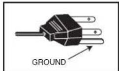
Do not attempt to bypass the safety purpose of the grounding type plug.
THIS UNIT IS NOT DISCONNECTED FROM THE MAINS UNLESS THE MAINS LEAD IS UNPLUGGED.
THE INSTALLER MUST MAKE SURE THE WATERPROOF INLINE COUPLER IS EASILY ACCESSIBLE.
Servicing
Your monitor is fully transistorised and does not contain any user serviceable components.
You must not remove the rear cover of the monitor by yourself. The apparatus is working with high voltages and could damage objects or even endanger people. Leave all required repair and service jobs to an authorised service technician. He will exclusively use such spare parts that are complying with the same safety standards as applicable to the original parts. The use of original spare parts can prevent fire, shock and other hazards.
Unplug the LCD monitor from the wall outlet and refer servicing to qualified service personnel under the following conditions:
If the power cord or plug is damaged.
If liquid has been spilt in to the LCD monitor.
If the LCD monitor has been dropped or the cabinet has been damaged.
If the LCD monitor exhibits a distinct change in performance.
If the LCD monitor does not operate normally by following the operating instructions.


Adjust only those controls that are covered in the operating instructions as improper adjustment of other controls may result in damage. This will often require extensive work by a qualified technician to restore the monitor to normal operation.
Important recycling information.

Your SANYO product is designed and manufactured with high quality materials and components which can be recycled and reused.
This symbol means that electrical and electronic equipment, at their end-of-life, should be disposed of separately.
In the European Union there are separate collection systems for used electrical and electronic products.
Please help us to conserve the environment we live in!
Note: This symbol mark and recycle system are applied only to EU countries are not applied to other countries of the world.
Declaration of Conformity: North America and Canada
Model Number: c42LM5WP
Trade name: Sanyo
Responsible party :SANYO FISHER COMPANY
Address: 21605 Plummer Street, Chatsworth, California 91311
Telephone:(818)998-7322
This device complies with Part 15 of the FCC Rules. Operation is subject to the following two conditions:
(1) this device may not cause harmful interference, and
(2) this device must accept any interference received, including interrence that may cause undesired operation.
AC Power Cord Requirement
The AC Power Cord supplied with this LCD monitor meets the requirement for use in the country in which you purchase it.
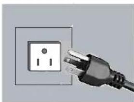
AC Power Cord for the United States and Canada:
AC Power Cord used in the United States and Canada is listed by the Underwriters Laboratories (UL) and certified by the Canadian Standard Association (CSA).
AC Power Cord has a grounding-type AC line plug. This is a safety feature to make sure that the plug will fit into the power outlet. Do not try to defeat this safety feature. Should you be unable to insert the plug into the outlet, contact your electrician.
THE SOCKET-OUTLET SHOULD BE INSTALLED NEAR THE EQUIPMENT AND EASILY ACCESSIBLE
End-User License
The product (meaning the equipment or appliance to which this documentation relates) incorporates Software (the software applications, utilities and modules embedded within the Product) which is owned by Sanyo or its licensors. Before using the product, please read the End-User License Conditions detailed below. If you do not agree to the terms and conditions of the End-User License, Please do not proceed to use the Product- repack the Product unused and return it to your supplier together with proof of purchase for a full refund. By using the product, you agree to be bound by the terms and conditions of the End-User License.
License Grant, Conditions and restrictions
- Sanyo grants you a non-exclusive, world-wide (subject to export controls), non-transferable (except as permitted by 2 below), royalty-free license to use the Software upon and with the Product.
- You may not transfer any of your license rights in the Software without the prior written consent of SANYO and if consent is provided then the Software shall only be transferred in conjunction with the transfer of the Product AND provided that the transferee has read and agreed to accept the terms and conditions of this license.
- You must ensure that the copyright, trademark and other protective notices contained in the Software are maintained and not altered or removed.
- The Software provided hereunder is copyrighted and licensed (not sold). SANYO especially does not transfer title or and ownership rights in the Software to you. The Software provided hereunder may contain or be derived from portions of materials provided to SANYO under license by a third party supplier.
-
Except as expressly permitted by statute you may not;
-
use the Software in conjunction with any other computer hardware other than the product;
- copy all or part of the Software;
-
incorporate all (or any of) the Software into other programs developed by (or on behalf of) you and/or used by you;
-
reverse-engineer, decompile or disassemble the Software;
- make the Software (or any part of it) available, or permit its redistribution, for use with any computer hardware other than the Product; or rent, lease, gift, loan, sell, distribute or transfer possession of the whole or any part of the Software.
Termination
This license is effective until terminated. This license will terminate automatically without notice if you fail to comply with any of its provisions.
Disclaimer
- The Software is (to the extent permitted by law) supplied 'as is' and SANYO and its suppliers expressly exclude all warranties, express or implied, including (but not limited to) warranties of satisfactory quality, fitness for purpose and non-infringement (save to the extent that the same are not capable of exclusion at law).
- In no circumstances will SANYO be liable for any direct, indirect, consequential, or incidental damage (including loss of profits, business interruption, loss of data or the cost of procurement of substitute goods, technology or services) arising out of the use or the inability to use the Software (save to the extent that such liability is not capable of exclusion at law).
General
- This End-User License will be governed by laws of England and the User may only bring claims in the English Courts and SANYO shall be entitled to bring a claim in the courts of any jurisdiction.
- This End-User License is governed by the laws of the State of California. The End-User and Sanyo agree that any action to enforce or interpret the terms of this End-User License shall be brought only in the appropriate state or federal court located in Los Angeles County, California. The End-User and Sanyo hereby submit to the exclusive jurisdiction and venue of such court.
- The above terms and conditions supersede any prior agreement, oral or written, between you and SANYO relating to the Software.
Step:1 Mains Connection
Connect the display unit to VGA, BNC and Scart connector as required.
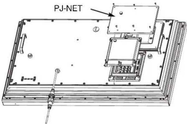
- Connect the in-line power connector to the connector attached to the LCD monitor as shown above.
- Connect the power cord of the LCD monitor to a wall outlet.
As this product does not have a mains On/Off switch, please ensure your mains plug is easily accessible.
The LCD monitor is prepared for a mains voltage AC100~240V, 50Hz/60Hz. To completely switch off the mains, or when the display unit is not to be used for an extended period of time, it is advisable to disconnect the power cord from the power outlet.
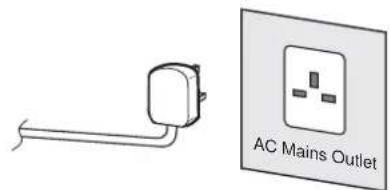

Please use the correct mains lead supplied with the set for your area.
3. Warning: To prevent injury, the unit must be securely attached to the wall in accordance with the installation instructions.

WARNING! High voltages are used in the operation of this set. Refer service to qualified service personnel.
Step:2 Connections
INPUT selection
To switch between AV1, RGB, AV2 (RGB H/V or Y, Pb, Pr) AV3, DVI or PC mode press the TV/ AV button on your remote control repeatedly or press and hold the TV/AV button for a few seconds and a selection menu will appear on screen.Use the 5 or 6 buttons to select the correct input.
1.AV1
SCART connection
2.RGB
TTL input (5V RGB signals) into SCART terminal
3. Y,Pb,Pr/ RGBHV connection (AV2)
This LCD monitor has a choice of Y, Pb, Pr or RGB H/V connections. You can connect your DVD player to the Y, Pb, Pr terminals instead of using a scart lead. This can support high definition in analogue component form. RGB H/V can be used as a PC input via the BNC terminals.Both options support a large range of resolutions (page 12).
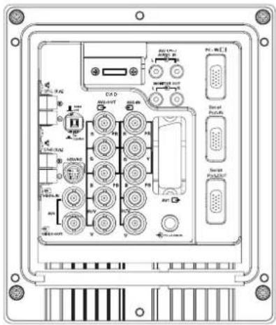
4.AV3
Composite (CVBS) signal input
AV3 OUT is to output the composite video signal from the VIDEO IN so that you can connect monitors with the use of a loop through function.
- RS232C IN/OUT: Is a input for external commands to control the monitor (see page 9).
6. DVI-D (Digital Video Interface)
This monitor has a DVI connector. This is located at the back of the monitor next to the phono sockets. This input will support a large range of resolutions as shown on page 12. See page 7 for details of menu operation.
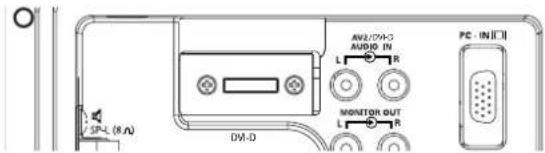
7 PC connection
This LCD monitor has a PC connector (PC-IN D-SUB). You can connect a PC to the LCD monitor and use it as a monitor display (see page 8). This input will support a large range of resolutions (see pg12). Audio can be connected via the 3.5mm PC audio in socket.
8. External Audio Output
To output the audio signal from AV 1,2,3, PC and DVI. The speaker impedance should be 8 ohms.
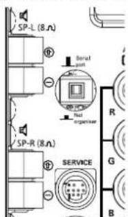
9.PJ Net IN/OUT: Has the ability for PJ-NET to be connected to control the monitor using a network.
10.Use of Monitor Audio Output Connections
The audio monitor out sockets on the rear of the set provide a fixed level audio output for reproducing sound via your audio equipment.
TV/AV button
To switch from AV1, RGB, AV2, AV3, DVI or PC mode press repeatedly or Press and hold in a few seconds, an AV selection menu appears. Select the mode you require using the 5 6 buttons
Screen mode selector
To select the screen mode, Natural, Full, Zoom, Title-in or Normal. Refer to page 10
MENU
To enter and exit the main menu, and sub menus.
Level up/down
To adjust the sound volume level, or enter sub menus
Picture mode selection
Press the button repeatedly to select the following picture modes.
Personal - Personal preference mode.
Dynamic - Suitable for brightly lit rooms.
Standard - Normal viewing mode.
Eco - Suitable for dimly lit rooms and gives a cinema - like effect.
Surround mode selector
To select the surround mode, OFF, MID, MAX
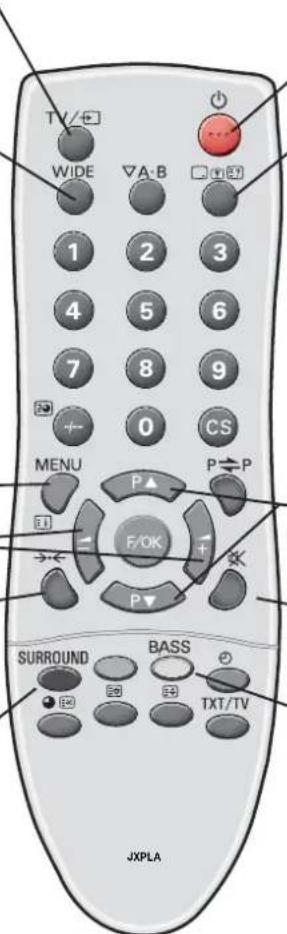
Standby
To switch the monitor on and off. Also see page 7
Recall
To display Input selection information and the
OFF Timer if set.
You can also select colour systems in AV mode as follows
AUTO->PAL->SECAM->NTSC3.58
Up and down
To select the next item
Sound mute
To mute the sound from the speakers.
The sound changes as follows;
Normal volume -> Mute
Bass expander
To get an emphasised bass sound ON or OFF.

Remote control battery installation
Install two "AA" 1.5 volt batteries so that the "+" and "-" marks on the batteries match the "+" and "-" marks inside the unit into the remote control handset.
Controls and Menus
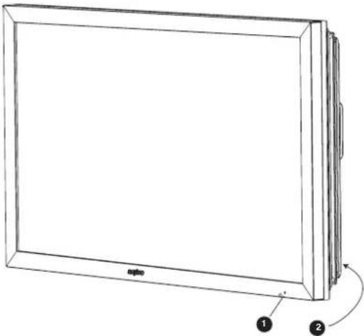
- The LCD display has a Standby light to show there is power.
Switching into/from standby mode
The Standby mode is used for switching the LCD monitor off for short periods of time. In standby mode the monitor is switched off but is still receiving mains power.
To turn the monitor into standby mode, press the 4 button. The blue power indicator illuminates more brightly.
To turn the monitor ON from standby mode, press any of the following buttons: 4, 5, 6 or 0-9 buttons.
If you find the power indicator flashing, disconnect power cord from the power outlet and contact our Service desk.
This warning is a sign to let you know that the power protection function of this TV set is now operating.
2. Control buttons (bottom corner of back cover)
Menu/F button: rotate between volume, Brightness, contrast, colour, sharpness and OSD language.


Input/ OK button: Switch between AV1, RGB, AV2, AV3, DVI and PC mode.
ed
buttons: provide up and down adjustments.
4 button: To switch to standby mode (to switch off completely disconnect the monitor from the power supply).
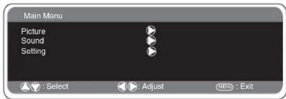
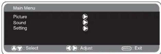
Menu Operation
Many of your monitors functions are controlled through the menu function, using the remote control handset.
MENU
During menu operation the bottom of the on screen display will show which controls can be used for menu navigation. Press the MENU button to enter the main menu.
A sub menu is selected using the 5 or 6 button and pressing the1 button when the required sub menu is highlighted. When you have finished you can press the MENU button to exit, then the MENU button again to exit the main menu.
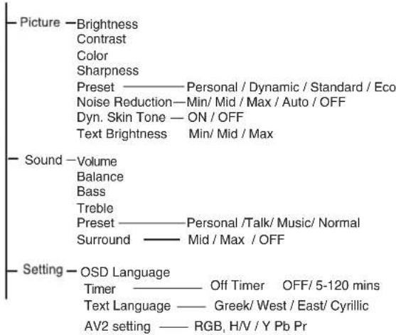
Picture menu
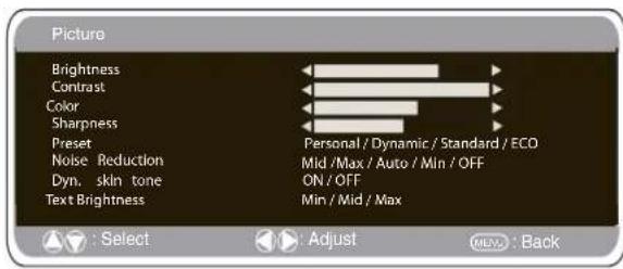
- Press the MENU button. Select Picture using the 5 or 6 button. Press the1 button to enter. Set the picture settings for your "personal" preference.
- Use the 5 or 6 button to select eg. Brightness and the 1 or2 button to adjust levels.
- Preset : You can select either your "Personal" settings, or Dynamic, Standard or Eco settings.
- Noise Reduction: May be used to reduce any local picture 'noise' (granular appearance) being experienced by using 1 or2 button to select between Mid / Max / Auto / OFF /Min.
- Dynamic skin tone: May be used to enhance skin tone by using 1 or 2 button to select between On / Off.
Tint : is only available if NTSC equipment is connected.
- Text Brightness: May be adjusted by using 1 or2 button to select between Min / Mid / Max.
Press the MENU button to return to Main Menu. These settings automatically store when you exit the menu.
Sound menu
Press the MENU button and select Sound using the 5 or 6 buttons, press the1 button to enter.
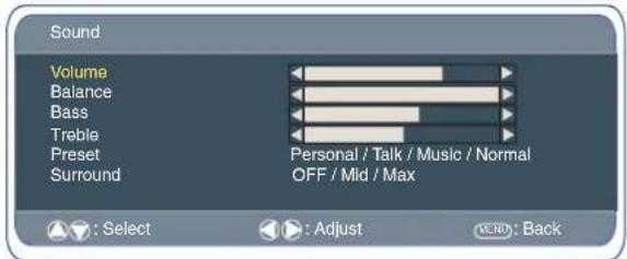
Select and adjust to obtain the best sound settings for your environment using the 5 or 6 and 1 or2 buttons. Press the MENU button to return to Main Menu. These settings automatically store when you exit the menu. Press the MENU button to exit menu.
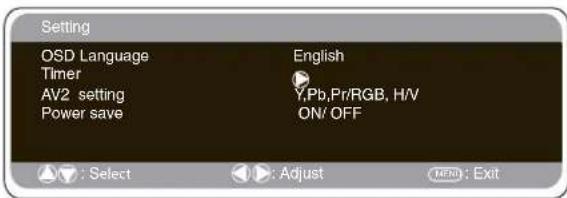
Setting menu
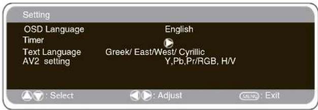
OSD Language
Use the 1 or 2 button to select the preferred OSD language (English, French, German, Italian, Spanish, Dutch). Press the MENU button to return to main menu.
Off-timer setting
The Off timer will switch the monitor into the standby mode when the selected time has elapsed.
Press the MENU button. Select Setting using the 5 or 6 button press the 1 button to enter. Select Timer using the 5 or 6 button, press 1 button to enter Timer Menu. Press the 1 or 2 button to change time.
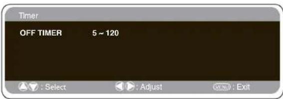
The time changes in 5 minute steps. The maximum time is 120 minutes. If you have set the off timer, a count down display appears in the corner of the screen when the recall button is pressed. If the monitor is switched off by the standby button 4 on the remote control or by the standby switch 4 on the back of the LCD monitor the timer settings will be cancelled.
Text Language
Press the MENU button. Select Setting using the 5 or 6 button press the1 button to enter.Select Text language using the 5 or 6 button. Press the 1 or 2 button to select West, East, Greek or Cyrillic. Press the MENU button to exit.
| WEST | EAST | GREEK | CYRILLIC | ||||
| ENGLISH | GERMAN | POLISH | ESTONIAN | ENGLISH | FINNISH | POLISH | SLOVENIAN |
| SWEDISH | ITALIAN | ROMANIAN | CZECH | GERMAN | DANISH | GERMAN | RUSSIAN |
| FINNISH | HUNGARIAN | SLOVAKIAN | CROATIAN | SWEDISH | HUNGARIAN | CROATIAN | LETTISH |
| FRENCH | SPANISH | GERMAN | SLOVENIAN | ITALIAN | FRENCH | ||
| TURKISH | DANISH | SLOVENIAN | TURKISH | ||||
| PORTUGUESE | GREEK | CROATIAN | |||||
AV2 setting
Press the MENU button. Select Setting using the 5 or 6 button press the 1 button to enter.
Select AV2 setting using the 5 or 6 button. Press the 1 or 2 button to select either Y,Pb,Pr or RGB H/V. Press the MENU button to exit, this automatically stores your changes. Press the MENU button again to exit the main menu.
PC menu settings
Connect your PC to either PC-IN or RGBHV on the rear of the set. Once connected select PC mode or AV2 (RGBHV, see page 5 for AV2 input settings) via the v button on your remote control. The set will become a monitor for the PC. By pressing the MENU button on the remote control a menu window will appear on screen, this allows the settings to be adjusted. To adjust the Picture settings select picture using the 5 or 6 buttons on the remote control then the1 button to enter the following picture settings menu.
Press the 1 or 2 buttons to adjust the Picture brightness and the same to adjust the contrast of the picture.
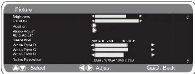
Picture position changes the picture horizontally and vertically. Press the1 button to enter the sub menus, adjustment is carried out using the1 or 2 buttons on the remote control. Video adjust changes the Phase and the clock of the screen. If the picture is blurred or grainy this function will adjust it to a clearer picture, adjustment is carried out using the 1 or 2 buttons on the remote control.
Auto Adjust will automatically centralize the picture by using the 1 button. This will change all the above settings automatically. Auto adjust can also be achieved by pressing the red button on the remote control without having to select the menu.
Resolution displays the current resolution of the picture. This is for information only and cannot be adjusted.
White tone: Using the 1 or2 buttons it is possible to adjust the colour tone of the picture using the White tone Red(R) / Green (G)/ Blue(B). This will adjust the picture to show more or less of the chosen colour. For example if red is selected you can adjust the proportion of red in the picture to increase or decrease using the 1 or 2 buttons. Native Resolution is used when the PC can output WXGA 1366 × 768 . The setting on your Monitor set can be changed to receive XGA/WXGA signal using the1 or 2 buttons. Once the native resolution has been selected, save the settings by switching the monitor off then on using the standby button.
For Sound settings refer to sound menu (Page 8)
Setting: Press the menu button on your remote control and use the 5 or 6 buttons to select Settings. The 1 button will enter the settings menu.
GB
PC OPERATION / INSTALLATION MENU/ RS232C
GB
PC menu settings
OSD Language, Timer and AV2 settings are the same as in all input modes (pg 8).
Power save if turned ON will switch the monitor into Powersave mode after 1 minute if no signal is detected, the LED light will turn a brighter blue to indicate stand by. The monitor will automatically turn back on when a signal has been detected (PC input / RGBHV). Use1 or 2 buttons to select power save ON or OFF. Press the menu button twice to initiate Powersave.
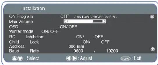
Installation Menu
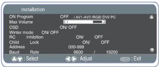
This LCD monitor allows you to set up the following:
SETTING PROCEDURE
- Press and hold the green button on the Remote control handset for 5 seconds.(Installation menu will appear)
- Use the 5 or 6 button to highlight each option, use the 1 or 2 button to adjust each option.
■ On Program
Select ON program using the 5 or 6 button, select the start up position using the 1 or 2 buttons. (Off / AV1 / RGB/ AV2/ AV3/ DVI/ PC) Press the MENU button to exit the menu.
Max Volume
Select Max volume using the 5 or 6 button, use the 1 or 2 buttons to set the maximum volume required.
OSD (On screen display)
Select OSD using the 5 or 6 button, select ON/OFF using the 1 or 2 buttons. Selecting OFF will inhibit the OSD. To re-instate OSD, press and hold the green button on the remote control to re-enter installation menu and select OSD ON.
Winter mode
This Function can be activated when the LCD monitor is used during cold temperature conditions, approximately 38^ / 4^ or below to maintain picture performance. Using the 5 or 6 button select winter mode, once highlighted you can select ON or OFF by pressing the 1 or 2 button. IMPORTANT: The AC cord should not be disconnected during the operation of Winter mode function. When in winter mode, power consumption is higher than normal standby consumption. This is entirely due to the operation of heating circuitry. We strongly recommend to turn off Winter mode when the ambient temperature is above 38^ / 4^ .
RC Inhibition
You can prevent unwanted remote control operation by selecting RC Inhibition. When selected an inhibit symbol will appear on screen when a button is pressed on the remote control. Select using the 5 or 6 button. Press the 1 or 2 button to select On or OFF. To re-instate RC operation press and hold the green button on the remote control and select RC inhibition OFF.
Child lock
You can prevent unwanted operation of the LCD monitor via the buttons on the rear of the monitor. Select using the 5 or 6 button. Press the 1 button to select On or OFF.
Disconnecting the mains supply before exiting installation menu will cancel the following features On program, RC inhibition, Address and Baud Rate.
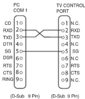
RS232C settings
This monitor can be controlled via the RS232C connector using a suitable computer/ control commands.
Serial Interface Specification
Transfer Specification
1. Transmission Speed: initial setting value is 19200.
2. Transmission speed can be changed via the Installation menu (see below baud rate)
| ITEM | SPECIFICATION |
| Synchronous system | Asynchronous |
| Transmission Speed | 9600 / 19200 |
| Data Length | 8 bit |
| Parity | None |
| Stop Bit | 1 |
| Flow Control | None |
Connection
The Designated RS-232C serial cable must be used for a connection to a computer and LCD monitor.
The TV command is defined by one command/ one line that starts with "C" and ends with carriage return. (0x0D)
There are two types of commands:
Functional Execution Command e.g Co5[CR] (table on page 64)
Status Read Commands e.g "CR0 [CR] (see table on page 64)
Setting the monitor address in RS232 mode
To Access Installation mode press the green button on the remote control and hold for 5 seconds. A new screen will appear.
Each monitor can have a specific Address for example 007, which enables the monitor to be controlled individually and will not affect other monitors connected to a controlling PC.
Address format command
The addressing format command is used for operating multiple monitor sets from a single PC via the RS232C command line. If you set your monitor address to '000', it will never respond to any addressing command from the PC. If the address from the PC is 'FFF', all monitor sets will execute the command. The Address format command is defined by one command, one line
The Address format command is defined by one command, one line which starts with 'A' and ends with carriage return. (0 x0D)
The Monitor starts to decode when it receives a carriage return.
(0x0D)
An address is added at the top of a control command
Example.
Functional execution command:
"A001C05" [CR] means address is 001 and the control command is C05
Status read command
"A001CR0"[CR] means address is 001 and command is CR0.
The monitor can set its own address in the Installation option menu (above) The address range is 000 - 999, the default address will be 000
The baud rate indicates the unit for transfer speed of data from the PC to the monitor sets
Selecting of picture size
Screen options
Today there are various transmission formats with different size ratios, eg. 4:3, 16:9 and video formats such as letterbox.
Press the WIDE button repeatedly to select your desired setting.
When in High Resolution (720p / 1080i) YPbPr or DVI, the picture will remain fixed in 16:9 format 'Full size' and may not be changed.
Natural
| 4:3 16:9 | Letterbox Video | |
| Stretches the picture horizontally to fill the screen. The picture is more stretched at the edges. | The picture fills the screen and is proportionally correct. | The black bars top and bottom remain and the height is compressed to fit the picture area. |
Zoom
| 4:3 | 16:9 | Letterbox Video |
| The correct picture width is maintained but the top and bottom are cropped. | Zooms in slightly cropping the top and bottom. | The black bars top and bottom are smaller and the picture height is compressed slightly. |
■ Title-In
| 4:3 16:9 | Letterbox Video |
| TILLE TILLE TILLE ON SCAH | TILLE TILLE TILLE ON SCAH |
| As Zoom (16:9), but bottom is compressed even more to allow subtles to be seen. | As Zoom (16:9), but bottom is compressed even more to allow subtles to be seen. |
Full
| 4:3 16:9 | Letterbox Video | |
| The whole screen is filled stretching the width. | The whole screen is filled with the correct picture ratio. | The black bars top and bottom are present and the height is compressed. |
Normal
| 4:3 16:9 | Letterbox Video | |
| The correct ratio is maintained with black bars on the left and right. | Black bars left and right, picture height is stretched. | Black bars left, right, top and bottom. |
Specification
Common spec
Power source
100~240V 50Hz / 60Hz
Colour system
PAL NTSC3.5,SECAM
AV terminal
AV1:Scart CENELEC Standard
Input: Composite video, RGB (5V RGB with 5V sync to
pin 14) and audio-L/R
Output: composite video and audio L/R
AV2:BNC
Input: RGB, H and V / Y, Pb, Pr and audio L/R
Output: RGB, H and V / Y, Pb, Pr
AV3:BNC
Input: Composite video
Output : Composite video
Audio Monitor.Out: CINCH L/R
Audio Speaker out: 2 × 6W
DVI Input: DVI-D GROUP Standard
PC Input: Mini D-SUB 15 PIN and
Audio 3.5mm Jack
Serial port: RS232C: Input / Output
Net Organiser: POA-LN01 (optional)
When ordering these products, give the Name and Type No. to the
sales dealer.
Contrast Ratio 1500:1
Screen(inches/cm) 42^ / 107 cm
-viewing measured
diagonally)
Display Native Resolution 1366 x 768 (WXGA)
Viewing angles H:178°, V:178°
Dimensions (WxHxDmm) 1027x620x167.5
Weight (kg) 40.7
Helpful hints
NO PICTURE, NO SOUND
-
Check if monitor is plugged in.
-
Check monitor is not in standby mode
POOR PICTURE, SOUND OK
Adjust BRIGHTNESS/ CONTRAST LEVELS (too low).
NO COLOUR, PICTURE OK
Adjust COLOUR control.
-
Check lead connections
-
Does the signal input have colour
■ REMOTE CONTROL DOES NOT WORK
-
Check batteries are inserted correctly
-
Check condition of batteries
-
Check to see if remote control inhibit is set ON
■ PICTURE OK, NO SOUND
-
Check external speakers are connected correctly
-
Check lead connections to external equipment
Volume turned down or mute selected
PC signal support timing
| Resolution | Horizontal Frequency (kHz) | Vertical Frequency (Hz) | Remark |
| 720_400 | 31.47 | 70.09 | DOS(VGA) |
| 640_480 | 31.50 | 60.00 | DOS(VGA VESA 60Hz) |
| 640_480 | 37.50 | 75.00 | VGA VESA 75Hz |
| 640_480 | 37.86 | 72.81 | VGA VESA 70Hz |
| 640_480 | 37.86 | 74.38 | VGA |
| 640_480 | 35.00 | 67.00 | Mac. |
| 640_480 | 34.97 | 66.60 | Mac LC 13" |
| 800_600 | 35.16 | 56.25 | SVGA VESA 5GHz |
| 800_600 | 37.90 | 60.32 | SVGA VESA 60Hz |
| 800_600 | 46.90 | 75.00 | SVGA VESA 75Hz |
| 800_600 | 32.70 | 51.09 | SVGA |
| 800_600 | 34.50 | 55.38 | SVGA |
| 800_600 | 37.90 | 61.03 | SVGA |
| 800_600 | 38.00 | 60.51 | SVGA |
| 800_600 | 38.60 | 60.31 | SVGA |
| 832_624 | 49.00 | 74.00 | Mac. |
| 1024_768 | 48.40 | 60.00 | XGA VESA 60Hz |
| 1024_768 | 56.50 | 70.00 | XGA VESA 70Hz |
| 1024_768 | 60.000 | 75.00 | XGA VESA 75Hz |
| 1024_768 | 44.00 | 54.58 | XGA |
| 1024_768 | 46.90 | 58.20 | XGA |
| 1024_768 | 47.00 | 58.30 | XGA |
| 1024_768 | 48.50 | 60.02 | XGA |
| 1024_768 | 58.03 | 72.00 | XGA |
| 1024_768 | 60.31 | 74.92 | XGA |
| 1024_768 | 61.00 | 75.70 | XGA |
| 1024_768 | 60.24 | 75.08 | MAC_Normal 19" |
| 1280_960 | 60.00 | 60.00 | SXGA VESA 60Hz |
| 1280_1024 | 79.976 | 75.025 | SXGA VESA 75Hz |
| 1280_1024 | 62.50 | 58.60 | SXGA |
| 1280_1024 | 63.370 | 60.01 | SXGA |
| 1280_1024 | 63.34 | 59.98 | SXGA |
| 1280_1024 | 63.74 | 60.01 | SXGA |
| 1280_1024 | 63.79 | 60.18 | SXGA |
| 1280_1024 | 63.90 | 60.00 | SXGA |
| 1280_1024 | 71.69 | 67.19 | SXGA |
| 1280_1024 | 76.97 | 72.00 | SXGA |
| 1280_1024 | 81.13 | 76.107 | SXGA |
| 1152_864 | 64.20 | 70.40 | SXGA |
| 1152_900 | 61.20 | 65.20 | SXGA |
| 1152_900 | 61.85 | 66.00 | SXGA |
| 1152_900 | 71.40 | 75.60 | SXGA |
| 1152_870 | 68.68 | 75.06 | MAC_Normal 21" |
| 1280_960 | 75.00 | 75.08 | Mac. |
| 1280_1024 | 80.00 | 75.00 | Mac.. |
| 1600_1200 | 75.00 | 60.00 | UXGA VESA 60Hz |
| 1366_768 | 48.36 | 60.00 | WXGA |
| 1360_768 | 47.70 | 60.00 | WXGA |
Component signal support timing
| Resolution H | horizontal frequency (KHz) | Vertical frequency (Hz) | Remark |
| 720x480 15 | 735 60i SDTV 480 | ||
| 720x576 15 | 625 50i SDTV 576 | ||
| 720x480 31 | 25 60p SDTV 4 80p | ||
| 720x576 31 | 25 50p DTV 576p | S | |
| 1280x720 45 | .00 60p HDTV 7 20p | ||
| 1280x720 37 | .50 50p HDTV 7 20p | ||
| 1920x1080 3 | 8.75 | 60i HDTV 1 080i | |
| 1920x1080 2 | 8.13 | 50i HDTV 1 080i |
DVI-D SIGNAL SUPPORT TIMING
| Resolution | Horizontal Frequency (kHz) | Vertical Frequency (Hz) | Remark |
| 640_480 | 31.43 | 59.88 | VGA VESA 60Hz |
| 640_480 | 37.86 | 72.81 | VGA VESA 72Hz |
| 640_480 | 37.5 | 75 | VGA VESA 75Hz |
| 640_480 | 34.97 | 66.6 MAC | LC 13" |
| 640_480 | 35 | 66.67 | MAC_NORMAL 13" |
| 800_600 | 35.16 | 56.25 | SVGA VESA 56Hz |
| 800_600 | 37.88 | 60.32 | SVGA VESA 60Hz |
| 800_600 | 46.875 | 75 | SVGA VESA 75Hz |
| 832_624 | 49.72 | 74.55 | MAC_NORMAL 16" |
| 1024_768 | 48.36 | 60 XGA | VESA 60Hz |
| 1024_768 | 60.23 | 75.03 | XGA VESA 75Hz |
| 1024_768 | 56.47 | 70.07 | XGA VESA 70Hz |
| 1024_768 | 60.24 | 75.08 | MAC_NORMAL 19" |
| 1152_870 | 68.68 | 75.06 | MAC_NORMAL 21" |
| 1280_1024 | 63.98 | 60.02 | SXGA VESA 60Hz |
| 720_480 | 31.7 | 59.94 | 480p |
| 768_575 | 31.25 | 50 | 575p |
| 1280_720 | 37.5 | 50 | 720p-50Hz |
| 1280_720 | 45 | 60 | 720p-60Hz |
| 1366_768 | 48.36 | 60 | WXGA |
| 1360_768 | 47.7 | 60 | WXGA |
| 1920_1080 | 28.125 | 50 | 1080i-50Hz |
| 1920_1080 | 33.75 | 60 | 1080i-60Hz |
Depending on the condition of signals and the type and length of cables, these signals may not be properly viewed. To save the native resolution 1366_768 setting switch the monitor off then on using the standby button.
Installation/Utilisation

Adresse: 21605 Plummer Street, Chatsworth, Californie 91311
Telephone: (818) 998-7322
Concession de license, conditions et restrictions
Dimensions (Lx H x P mm) 1027x620x167.5
Poids (kg) 40.7
Conseils Pratiques
PAS D'IMAGE NI DE SON
PAS DE COULEURS, IMAGE CORRECTE
DIESES PRODUKT MULLS GEERDET WERDEN.
Adresse: 21605 Plummer Street, Chatsworth, California 91311
Telefon: +1 - (818) 998-7322
Audio Monitor Out: CINCH:L/R
DIT PRODUCT MOET GEAARD ZIJN
Adres:21605 Plummer Street, Chatsworth, California 91311
Telefoon:(818)998-7322
6. DVI-D (Digital Video Interface)
AV1: SCART CENELEC standard
Audio speakeruit:2x6W
Laboratories (UL) e alla Canadian Standard Association (CSA).
SANYO Industries (U.K.) Limited
Oulton Works, School Road, Lowestoft,
Suffolk, NR33 9NA, United Kingdom.
Consiglio Utili
QUANDONONE'PRESENTENEGSUONONEIMAGINE
Parte responsible :SANYO FISHER COMPANY
PC signal support timing
| Resolution | Horizontal Frequency (kHz) | Vertical Frequency (Hz) | Remark |
| 720_400 | 31.47 | 70.09 | DOS(VGA) |
| 640_480 | 31.50 | 60.00 | DOS(VGA VESA 60Hz) |
| 640_480 | 37.50 | 75.00 | VGA VESA 75Hz |
| 640_480 | 37.86 | 72.81 | VGA VESA 70Hz |
| 640_480 | 37.86 | 74.38 | VGA |
| 640_480 | 35.00 | 67.00 | Mac. |
| 640_480 | 34.97 | 66.60 | Mac LC 13" |
| 800_600 | 35.16 | 56.25 | SVGA VESA 56Hz |
| 800_600 | 37.90 | 60.32 | SVGA VESA 60Hz |
| 800_600 | 46.90 | 75.00 | SVGA VESA 75Hz |
| 800_600 | 32.70 | 51.09 | SVGA |
| 800_600 | 34.50 | 55.38 | SVGA |
| 800_600 | 37.90 | 61.03 | SVGA |
| 800_600 | 38.00 | 60.51 | SVGA |
| 800_600 | 38.60 | 60.31 | SVGA |
| 832_624 | 49.00 | 74.00 | Mac. |
| 1024_768 48.40 | 60.00 | XGA VESA 60Hz | |
| 1024_768 56.50 | 70.00 | XGA VESA 70Hz | |
| 1024_768 | 60.000 | 75.00 | XGA VESA 75Hz |
| 1024_768 44.00 | 54.58 | XGA | |
| 1024_768 46.90 | 58.20 | XGA | |
| 1024_768 47.00 | 58.30 | XGA | |
| 1024_768 48.50 | 60.02 | XGA | |
| 1024_768 58.03 | 72.00 | XGA | |
| 1024_768 60.31 | 74.92 | XGA | |
| 1024_768 61.00 | 75.70 | XGA | |
| 1024_768 60.24 | 75.08 | MAC_Normal 19" | |
| 1280_960 | 60.00 | 60.00 | SXGA VESA 60Hz |
| 1280_1024 | 79.976 | 75.025 | SXGA VESA 75Hz |
| 1280_1024 62.50 | 58.60 | SXGA | |
| 1280_1024 | 63.370 | 60.01 | SXGA |
| 1280_1024 63.34 | 59.98 | SXGA | |
| 1280_1024 63.74 | 60.01 | SXGA | |
| 1280_1024 63.79 | 60.18 | SXGA | |
| 1280_1024 63.90 | 60.00 | SXGA | |
| 1280_1024 71.69 | 67.19 | SXGA | |
| 1280_1024 76.97 | 72.00 | SXGA | |
| 1280_1024 81.13 | 76.107 | SXGA | |
| 1152_864 64.20 | 70.40 | SXGA | |
| 1152_900 61.20 | 65.20 | SXGA | |
| 1152_900 61.85 | 66.00 | SXGA | |
| 1152_900 71.40 | 75.60 | SXGA | |
| 1152_870 68.68 | 75.06 | MAC_Normal 21" | |
| 1280_960 75.00 | 75.08 | Mac. | |
| 1280_1024 80.00 | 75.00 | Mac_. | |
| 1600_1200 | 75.00 | 60.00 | UXGA VESA 60Hz |
| 1366_768 | 48.36 | 60.00 | WXGA |
| 1360_768 | 47.70 | 60.00 | WXGA |
Component signal support timing
| Resolution Horizontal frequency (KHz) | Vertical frequency (Hz) | Dot Clock Frequency(Mhz) | Remark |
| 720x480 15 | 735 60i 12.27 SDTV 4 80i | ||
| 720x576 15 | 625 50i 13.50 SDTV 5 76i | ||
| 720x480 31 | 25 60p 27 SDTV 4 80p | ||
| 720x576 31 | 25 50p 27 HDTV 5 76p | ||
| 1280x720 45 | 00 60p 74.25 HDTV V 720p | ||
| 1280x720 37 | 50 50p 74.25 HDTV V 720p | ||
| 1920x1080 | 33.75 | 60i 74.25 | HDTV 10 80i |
| 1920x1080 | 28.13 | 50i 74.25 | HDTV 10 80i |
| 1920x1080 | 31.25 | 50i 74.25 | HDTV 11 52i |
DVI-D SIGNAL SUPPORT TIMING
| Resolution | Horizontal Frequency (kHz) | Vertical Frequency (Hz) | Remark |
| 640_480 | 31.43 | 59.88 VGA VESA 60Hz | |
| 640_480 | 37.86 | 72.81 VGA VESA 72Hz | |
| 640_480 | 37.5 | 75 | VGA VESA 75Hz |
| 640_480 | 34.97 | 66.6 | MAC LC 13" |
| 640_480 | 35 | 66.67 | MAC_NORMAL 13" |
| 800_600 | 35.16 | 56.25 SVGA VESA 56Hz | |
| 800_600 | 37.88 | 60.32 SVGA VESA 60Hz | |
| 800_600 | 46.875 | 75 SVGA VESA 75Hz | |
| 832_624 | 49.72 | 74.55 | MAC_NORMAL 16" |
| 1024_768 | 48.36 | 60 | XGA VESA 60Hz |
| 1024_768 | 60.23 | 75.03 | XGA VESA 75Hz |
| 1024_768 | 56.47 | 70.07 | XGA VESA 70Hz |
| 1024_768 | 60.24 | 75.08 | MAC_NORMAL 19" |
| 1152_870 | 68.68 | 75.06 | MAC_NORMAL 21" |
| 1280_1024 | 63.98 | 60.02 | SXGA VESA 60Hz |
| 720_480 | 31.7 | 59.94 | 480p |
| 768_575 | 31.25 | 50 | 575p |
| 1280_720 | 37.5 | 50 | 720p-50Hz |
| 1280_720 | 45 | 60 | 720p-60Hz |
| 1366_768 | 48.36 | 60 | WXGA |
| 1360_768 | 47.7 | 60 | WXGA |
| 1920_1080 | 28.125 | 50 | 1080i-50Hz |
| 1920_1080 | 33.75 | 60 | 1080i-60Hz |
Depending on the condition of signals and the type and length of cables,
these signals may not be properly viewed.
To save the native resolution 1366_768 setting switch the monitor off then on
Functional Execution Command Table
| Command | Item | Comment |
| C00 | Power ON | |
| C01 | Power OFF | |
| C23 | Wide "Auto" direct | |
| C24 | Wide "Natural" direct | |
| C29 | Wide "Full" direct | |
| C0F | Wide "Normal" direct | |
| C30 | Picture | Toggle (Dynamic, Standard, Eco, Perconal) |
| C70 | AV1 direct | |
| C71 | RGB direct | |
| C72 | AV2 RGBHV direct | |
| C73 | AV2 YPbPr direct | |
| C74 | AV3 direct | |
| C75 | DVI direct | |
| C76 | PC direct | |
| C64 | PC Auto adjust | |
| C92 | Factory settings | |
| CF PSAVE ON | Power save ON | |
| CF PSAVE OFF | Power save OFF | |
| CF CLOK ON | Child Lock ON | |
| CF CLOK OFF | Child Lock OFF | |
| CF DEA RMCY | RC inhibition OFF | |
| CF DEA RMCN | RC inhibition ON |
--"__means "No Function".
Status Read Command Table
| Command | Item | Note |
| CRO | Power | On, Standby, power error,... |
| CR1 | Input Mode | AV1, AV2,..., HDMI, PC |
| CR WIDE | Wide Mode | Auto, Normal, Full,... |
| CR PICTURE | Picture mode | Dynamic, Standard, ... |
| CR SIGNAL | Signal existence | Signal / No signal |
| CR CHILD | Child Lock | On / Off |
| CR PSAVE | Power Save (On/Off) | On / Off |
| CR TM | Panel operating time |
"---_means "No Function"
Part No. 1KA6P1P0366-B
N4JS
Interactive Touchscreen User Guide
For serial Interface
For use with models:
42LM4WPTC
42LM5WPTC
42LM4RTC
42LM5RTC
TABLE OF CONTENTS
ABOUT THIS MANUAL 4
CONTACT INFORMATION. 4
SHIPPING DAMAGE/UNPACKING 4
CARE AND CLEANING OF THE TOUCHSCREEN 4
INTRODUCTION 5
COMPATIBILITY 5
INSTALLATION 6
LOADING THE TOUCH DRIVER SOFTWARE ONTO PC 6
STARTING THE DRIVER CONTROL PROGRAM 7
CONFIGURING THE COMMUNICATIONS PORT 7
EXPLANATION OF THE STATUS SECTION 8
ADJUSTING THE TOUCH SENSITIVITY LEVEL 10
CALIBRATION 12
SETTING THE TOUCH OUTPUT TO SUIT THE APPLICATION PROGRAM 13
DIAGNOSTICS AND FREQUENTLY ASKED QUESTIONS 15
MOTOR MODE 16
USING EDGE ENHANCEMENT 17
DELAYED STARTING OF THE DRIVER OUTPUT 17
FAULT FINDING GUIDE 18
DRIVER DOES NOT SEE THE TOUCHSCREEN 18
TOUCHSCREEN PERFORMS BADLY NEAR THE EDGES OF THE DISPLAY 18
FALSE touches 18
FAILURE TO SEE TOUCH EFFECT 18
MOUSE MOVEMENT IS NOT SMOOTH 18
CHANGES TO THE DRIVER ARE NOT BEING SAVED 18
MOUSE CURSOR MOVES RANDOMLY OR SEEMS STUCK 18
PROBLEMS WITH WINDOWSTM AUTOMATICALLY RUNNING THE DRIVER FROM START-UP .. 18
SLOW TOUCH SCREEN RESPONSE WHEN USING POWER HUNGRY APPLICATIONS 18
CHECK OR CHANGE THE VIRTUAL MEMORY SETTINGS 19
DRIVER PRIORITY CHANGE 19
ABOUT THIS MANUAL
This manual is intended as a reference guide for the Interactive Touchscreen running under Windows XP™ or Windows Vista™.
This User Manual provides the information needed to set up the touchscreen. In addition, this manual describes basic technical information about the touchscreen and troubleshooting.
CONTACT INFORMATION
If you have any questions or issues, please contact your original equipment supplier.
SHIPPING DAMAGE/UNPACKING
Every precaution is taken in testing and packing this monitor prior to shipment.
On delivery of the monitor, check the shipping carton for damage. If any damage is seen that could have caused damage to the contents, keep all packing materials for later inspection by the carrier who are responsible for any shipping damage.
CARE AND CLEANING OF THE TOUCHSCREEN
Thorough cleaning of the touch screen should be performed regularly in order to assure optimum performance.
The touch screen surface should be kept free of dust, dirt, fingerprints and other foreign material as contamination of the screen can affect its optical properties such as brightness and clarity of image.
Use a soft, clean, slightly damp cloth with any commercially available window cleaner for cleaning the glass surface of the touch screen. Avoid applying the cleaner directly onto the screen but apply it to the cloth instead.
INTRODUCTION
This manual will explain the workings and setup of the touchscreen fitted to your display. An explanation of the monitor and its workings is covered in the Monitor Manual that came with this product. The following pages will tell you how to install the software needed by the touchscreen to function and go through the adjustments that user's can change to enable the screen to perform effectively in many different environments.

The Ma7 Driver software has been written to interface between the Interactive Touchscreen and a computer running the Windows XPTM operating system.

Windows Vista
Limited testing has been carried out using Windows Vista™ with no noticeable issues. Further testing is ongoing.
Contact your supplier for more information on other operating systems.
The software comes in three executable files:
The Driver (Ma7_Driver.exe) controls the mouse pointer and activates the mouse left button in various modes when a user touches the touchscreen.
The Control Program (Ma7_Control_En.exe) is used to set up the driver.
The Setup Program (Ma7_Setup_En.exe) is used to set up the calibration and sensitivity of the driver from the touchscreen without using the mouse.
The configuration of the touchscreen is stored in a file called Ma7.ini, this file is saved in the same directory as the Ma7_Driver.exe file. Once set up, only these files are required to run the driver.
COMPATIBILITY
This program is compatible with Windows XPTM.
Limited Windows Vista™ testing has not shown up any issues with running the touch software but has shown up an issue with one of the program element; Ma7_Setup_En.exe. Further tests are ongoing. In the mean time see the installation instructions listed for Windows Vista™.

The default settings for the touchscreen driver disable the mouse cursor movement of the touchscreen. The user must enable this in the later stages of the touchscreen driver setup. You must save the configuration before closing the Ma7_Control.En.exe program after the following setup procedure.
INSTALLATION
LOADING THE TOUCH DRIVER SOFTWARE ONTO PC
- Switch on monitor

Do not plug the touchscreen interface cable into your computer.
- Insert the 'Information & Touch Software installation CD' into the PC and follow the automatic installation instructions.
If the installation does not start automatically;
- Click START on the Windows™ Taskbar; then click RUN.
- Type d:\Autorun.exe where d is the letter of your CD-ROM drive. Click OK
- Select the 'Touch software' button from the on-screen menu.
The software will create a subdirectory call TouchScreen on your PC in the 'Program Files' sub directory and copy all the relevant files necessary to run the touchscreen into it. Once completed, 'launch the application' will finish the installation. Please follow the instructions in the next section to complete the installation and the setting up of your touch screen.

Windows Vista™ users; When the installation has finished and the
dialogue box asks if you want to launch the application, un-tick the box. Instead, Select
'Start', 'All Programs', 'Touchscreen' and select Ma7_Control_En.exe to continue.
STARTING THE DRIVER CONTROL PROGRAM
Connect the touchscreen cable to a free serial port of the.
- If the Touchscreen control panel is not already running, start the driver by clicking the icon on the desktop or select the Windows™ START button and RUN "Ma7_Control_En.exe" with the necessary path or double click Ma7_Control_En.exe from 'Windows Explorer™' or click the short cut placed on the desktop.
When the program is started it displays the following window (Fig 1):
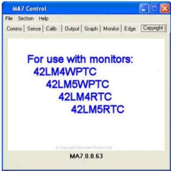
Fig 1
CONFIGURING THE COMMUNICATIONS PORT
When the program has loaded:
- Select the Comms tab.
- Select the comm port the Touchscreen is connected to.
- Make sure the driver box called 'Present' is red and select the appropriate port that the
touchscreen is connected to - Select a Baud rate of 19,200.
- Tick the 'Open' box in the Status section.
- When the driver recognizes the screen, the Open, Active and Valid boxes will go red (fig 2).
- The button called Reset will reset the touchscreen driver when pressed.
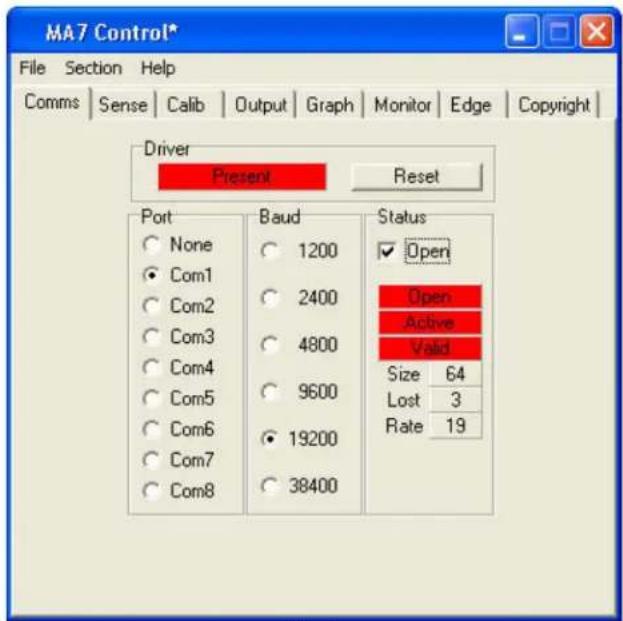
Fig 2
EXPLANATION OF THE STATUS SECTION
- The following explanation of the Status section assumes that the touchscreen is physically attached to a serial port of the PC:
Open - will go red and remain red only when the driver is present, the correct port is chosen and the Baud rate is set correctly.
If the Open box does not go red then the driver is not loaded or another driver has taken the port.
If the Open box goes on and off repeatedly then the driver is loaded but another piece of hardware is on that port or the Baud rate is set incorrectly.
Active - will go red and remain red only when the driver is present, the correct port is chosen and set to the correct Baud rate and when Open is red.
Active - will flash on and off to indicate there is activity on the port but it is some other hardware device.
Valid - will only go red and remain in this state when both Open and Active are red and the Baud rate is set correctly.
Only when Open, Active and Valid boxes have all changed to red and remain red is the touchscreen ready for the next stage of driver setup.
When communications exist between the driver and the touchscreen, the three boxes Size, Lost, Rate, will display data. These indicate the following information:
Size - number of wires in the touch sensor.
Lost - how many data scans have not been captured by the driver.
Rate - how many scans of the touchscreen per 1 second.
Reasons why the driver does not see the touchscreen are usually:
- Touchscreen is on a different port to the one selected
The Baud rate is incorrect - Another device, driver or program is using the port

The mouse pointer will not respond to a touch until it has been enabled in the
Output section of the Control Program. Details of this will follow later in this manual.
The Reset button loads fresh data from the touchscreen. This is used as a reference for detecting any new touches. This may be necessary if the touchscreen environment has been changed; for example, the touchscreen has been moved.
When you receive your unit, the sensitivity settings will have been optimised when the unit was manufactured. These settings should only be altered if you are experiencing problems such as an electrically noisy environment. Contact your supplier if you need further explanation.
- To select the sensitivity setup click on the Sense tab.
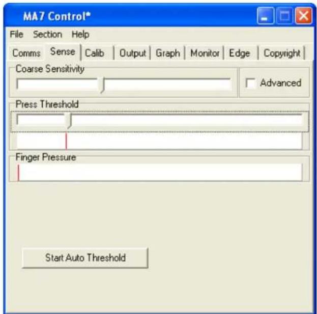
Fig 3
- First set the Course Sensitivity to approximately two thirds by dragging the bar with your mouse.
- Set the Press Threshold to approximately one third by dragging the bar with your mouse.
- Click on Start Auto Threshold. The following image appears:
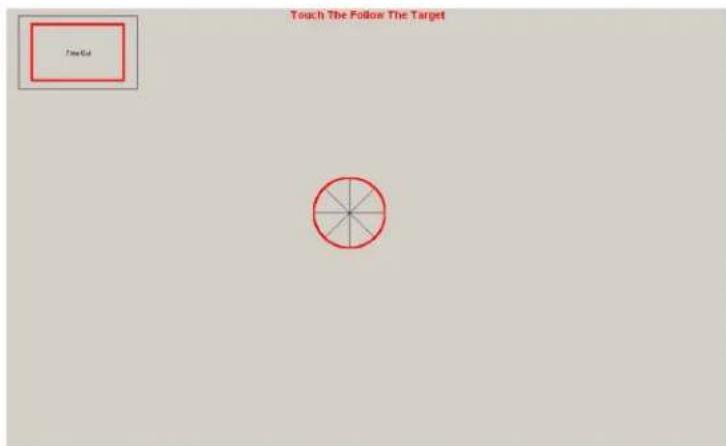
Fig 4
- Place your finger over the centre red circle (Fig4.) and follow it with your finger until it turns green, then remove your finger. The automatic adjustment of sensitivity is now complete and the screen returns to Fig 3.
Manual Sensitivity Setup
-
The Coarse Sensitivity slider is used to set the sensitivity of the touchscreen. If the slider is set to the right, the touchscreen is more sensitive to detecting a touch. More or less sensitivity may be required, dependent upon glass thickness or if the system is to be used with gloved hands.
-
The moving indicator under Finger Pressure shows the strength of touchscreens signal. Nominally the Coarse Sensitivity slider is adjusted so the Finger Pressure indicator moves about a third of the way along in response to a light touch.
- The Press Threshold slider is used to adjust the sensitivity of the touch to simulate a mouse button press. The driver recognises a touch when the Finger Pressure indicator exceeds the position of the Press Threshold slider. As default this is the same sensitivity level as required for mouse movement.
- To make certain that the touch is sensitive enough all over the display area, move a finger around the touchscreen and make certain that the Finger Pressure indicator always exceeds the Press Threshold slider position.
CALIBRATION
- Select the Calib tab as shown below (Fig 5), click the 'Start Calibration' box.
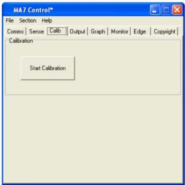
Fig 5
- You will see the following screen (Fig 6); there are three targets to touch in total, like the one shown below:
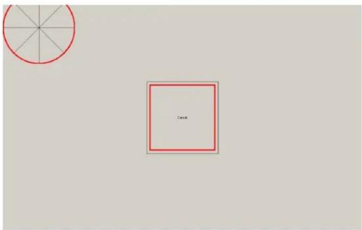
Fig 6
- When each of these targets is displayed, touch and hold your finger on the centre of the circular target. You must touch all three targets in turn.
- The red circle in the target slowly moves towards the centre of the target.
- Remove your finger only when the next target appears and touch that one.

If the touch calibration is not correct after this procedure, please run the process
again and adjust your finger position on the targets to compensate for the misalignment.
SETTING THE TOUCH OUTPUT TO SUIT THE APPLICATION PROGRAM
1. Select the Output tab.
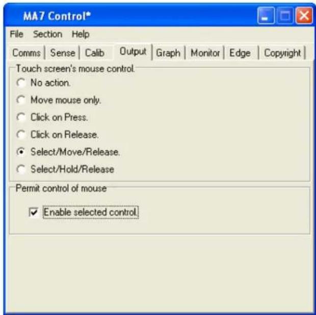
Fig 7
- Select the mouse control required for your application (Fig 7).

To enable the touch function on the screen, tick the Enable check box.
- No action selects no mouse pointer movement or button pressing when touching the touchscreen.
- Move mouse only enables mouse pointer movement but no button movement when touching the screen.
- Click on press enables mouse pointer movement and left button click when touching the screen.
- Click on release enables mouse pointer movement when touching the screen and left button click when the finger moves away from the touchscreen. This can be used in applications where the user needs confirmation the correct target has been selected before being activated with a button click by removing the finger.
- Select/Move/Release (Previously Drag and Drop) enables the mouse pointer movement and left button down when the screen is touched. The left button stays down as the finger is moved around the screen and left button click up does not occur until the finger is removed from the screen. The item selected is dragged around the screen following the mouse cursor movement and it is released only when the finger is removed from the screen.
- Select/Hold/Release enables the mouse pointer movement and left button down when the screen is touched. The left button stays down as the finger is moved around the screen and left button up does not occur until the finger is removed from the screen. The item selected remains selected but remains in its original position, it stays selected until the finger is removed from the screen.
This mode is useful for Web pages where scroll bars can be manipulated by touching the end buttons but text cannot be highlighted. If the user selects a target and then moves away from target when removing the finger, the target selection is still valid.
You must now save the settings
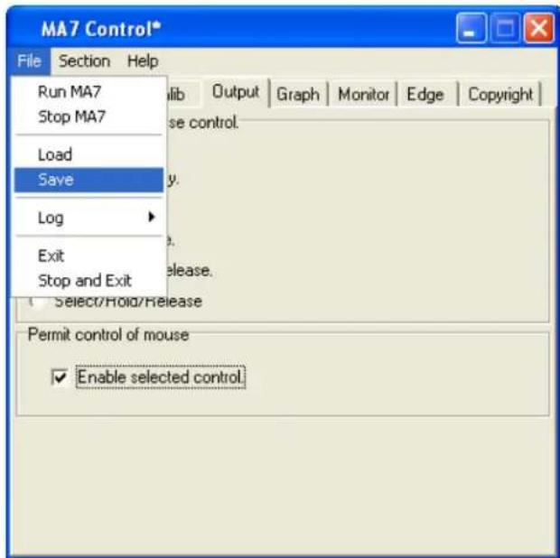
Fig 8
- (Fig 8) Click on file.
- Click on save to save the current settings.

When the touchscreen driver has been set up and there is no requirement to
change it.
DIAGNOSTICS AND FREQUENTLY ASKED QUESTIONS
Testing the Hardware with 'Graph'
- Select the Graph tab.
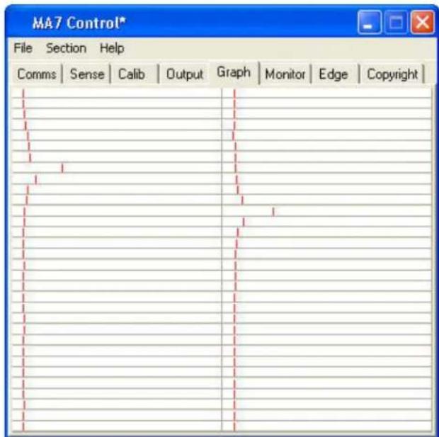
Fig 9
- Run a finger around the sensor, the effect of the finger on nearby wires can be seen by a visible movement on the indicators (Fig 9), each representing one wire. The algorithm in the driver interpolates the response curve to generate an accurate co-ordinate for the finger position.
The following hardware checks can now be made:
Wire Integrity Test
- Run a finger in both horizontal and vertical directions slowly and check that each wire indicator moves in a similar manner to the others. This test will identify touchscreen hardware and communication problems, which must be resolved before continuing with the driver setup. Contact your supplier for more information.
Signal to Noise Check
-
There will always be some noise pickup on the touchscreen; this can be seen by slight movement of the 64 indicators. The system can cope with this providing the noise is not excessive. Compare the signal strength of a finger against the noise. The touchscreen should function acceptably providing the peak noise is no more than one-third worst-case signal strength.
-
If the system is very noisy then the source of the noise must be investigated. The most likely source is high voltage switching near the touchscreen from nearby electronics. Try solving problems by earthing metalwork or moving the display further away. If the problem persists, contact your supplier.
Inter-Wire Linearity
- Checking the shape of the waveform in response to a touch may assist in setting up the Inter-Wire Linearity described in the Monitor section.
MONITOR MODE
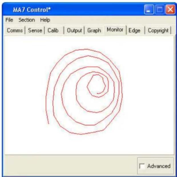
Fig 10
- This section is used to check the output of the touchscreen over the whole display area represented by the white box in the centre. It is useful in checking for any dead areas on the touchscreen and the performance of the touchscreen being able to follow the finger accurately and responsibly (Fig 10).
- When using this feature make sure that the touchscreen output is disabled by un-ticking the Enable Selection Control in the output section. When the finger is removed for a few seconds the display will automatically clear for more testing.
- When the Advanced box is ticked the Inter-Wire Linearity can be adjusted if necessary. This allows the driver to handle different response curves caused by different sizes of touchscreen and different glass thickness.
- The linearity can be adjusted for correct positioning between the wires. The default setting is centre, which should be satisfactory for most applications (Fig 11/12).
- If the touch sensor is large and there is a large gap between the wires or the signal is very strong the slider may need to be moved to the right. This is because the peak is very strong and involves very few wires and the algorithm to select touch position needs to change.
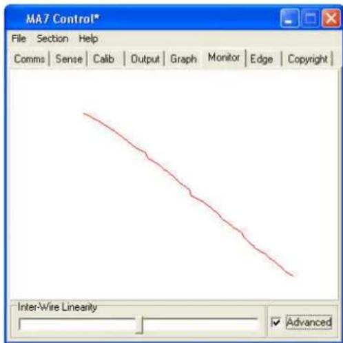
Fig 11
Inter-Wire Linearity set correctly
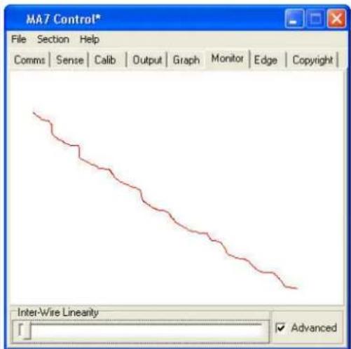
Fig 12
Inter-Wire Linearity set incorrectly
USING EDGE ENHANCEMENT
- To allow easy access to the sliders and buttons at the edge of the display, the cursor can be positioned nearer the edge of the screen. The amount of enhancement can be adjusted via the screen shown.
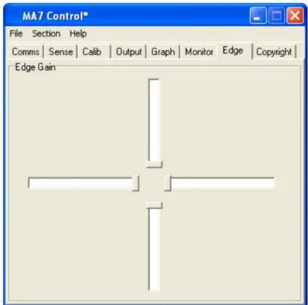
Fig 13
- Each of the sliders represents one edge of the sensor; the default position is as illustrated above (Fig 13).
- Edge Gain can also be used to counteract the effects of nearby metalwork that surrounds the display area.
- The further the sliders are away from the centre, the greater enhancement is given to the appropriate edge.

Too much edge enhancement will force the cursor to the edge of the display, it may not have the desired effect.
DELAYED STARTING OF THE DRIVER OUTPUT
- When starting a touchscreen computer system, it is sometime desirable to be able to prevent users from interfering with the start-up procedures from the touchscreen. Delaying the action from the touchscreen driver to the application can do this.
- This can be done by editing the MA7.ini file. This is found in the same directory as the MA7_Control_En and MA7_Driver_En programs. There is a line, StartDelayInt1=0. By changing the 0 to a number between 1 and 120 adds a delay of up to 120 seconds between the time when the driver is loaded and when it can be used to control an application program.
FAULT FINDING GUIDE
The following are some possible reasons why the touch screen might not work. If they do not solve your problem or you have a situation not covered please contact your supplier.
Touchscreen on a different comm port than the one selected.
The Baud rate is incorrect.
Another device, driver or program is using the port.
TOUCHSCREEN PERFORMS BADLY NEAR THE EDGES OF THE DISPLAY
Metal framework near to the touchscreen may interfere with the touchscreens performance. This effect can be diminished by increasing the distance between metalwork and the touch sensor or by coating the metalwork with an insulating paint or plastic coating. The driver can compensate by utilising the Edge Enhancement feature described in this document. The effects of the framework can be stabilised if it is grounded.
FALSE touches
If the noise on the system is great, then the Finger Pressure indicator may move by small amounts without the presence of a finger. If the Press Threshold is set too low, then the noise on the system could trigger false touches. This can be remedied by adjusting Coarse Sensitivity to a lower level, thus making the system less sensitive.
FAILURE TO SEE TOUCH EFFECT
The default settings for the touchscreen driver are set so that the mouse cursor movement is disabled during setup. The user must enable this output option by following Setting the Output Mode for the Driver.
If the selected option is enabled and touches are still not being registered, then adjustment to the Press Threshold is required to ensure the setting is to the left of the Finger Pressure indicator, all over the display area, when a finger is present.
MOUSE MOVEMENT IS NOT SMOOTH
Refer to Monitor Mode and the effects of Inter-Wire Linearity. Adjustment to the Press Threshold may be required to ensure the setting is to the left of the Finger Pressure indicator, all over the display area, when a finger is present.
CHANGES TO THE DRIVER ARE NOT BEING SAVED
Make sure that after making changes to the setup program that the Save command is used, in the File pull down menu. Make sure no other versions of Ma7.ini files exist on the system, this problem normally occurs when an old Ma7 files exists in a Windows™ main directory.
MOUSE CURSOR MOVES RANDOMLY OR SEEMS STUCK
For the touchscreen to work properly and effectively, it must be provided with a steady environment, therefore if the monitor is moved, this will upset the system. The driver should reset itself. However, a reset can be forced. Alternatively, by pressing CTRL+ALT+DELETE, the driver can be stopped from running and restarted by selecting File and Run Ma7 to restart.
PROBLEMS WITH WINDOWSTM AUTOMATICALLY RUNNING THE DRIVER FROM START-UP
If it is required to start the driver every time Windows™ is started then a short-cut to Ma7_Driver.exe can be put in the Start-Up folder. The program itself must NOT be put into the Start-Up menu. If this is done then the driver will place a copy of the Ma7.ini into the start-up menu and Notepad will open and display the Ma7.ini file information. To correct this problem the machine must be returned to pre-MA7 driver installation condition. ALL MA7 related files must be removed from the machine including the Start-up Menu and the driver re-installed.
SLOW TOUCH SCREEN RESPONSE WHEN USING POWER HUNGRY APPLICATIONS
There are several ways to improve system performance.
Optimise the Background performance against the Applications, to do this follow the simple instructions below:
Select the Windows™ START Button; go into Settings and Control Panel. Open the System folder and select the Advance tab.
Press the Performance Options button.
Change the selection from Optimise Performance for Applications to Optimise Performance for Background Services.
CHECK OR CHANGE THE VIRTUAL MEMORY SETTINGS
In the System folder under Advanced change the size of the page file. The rule of thumb is that the page size should be 112 times bigger than the installed Ram. Therefore if the system has 256MB of ram the page size should be 384MB. If Page size is less than the above rule change it. If this rule has been followed then increase the size by say 3 times. Check the system performance each time the size has been increased.
DRIVER PRIORITY CHANGE
All Programs and Applications are given a priority in windows™. Increasing the priority given to it by Windows™ can boost the performance of an application. The user can do this as follows: Run Task Manager by pressing CTRL, ALT and DELETE in that order and all at the same time.
Select Task Manager followed by Processes.
Scroll down the list of running processes until the MA7 driver is found and right-click it.
Highlight the Set Priority and the following list should appear:
LOW, BELOW NORMAL, NORMAL, ABOVE NORMAL, HIGH and REALTIME
The driver should be running in NORMAL, change this to ABOVE NORMAL.
Test the response of the touch screen, the highest recommended setting is HIGH.

Do not select REALTIME as this would set the driver priority to be the same as the operating system itself; this can make the Windows™ operating system unstable.

A priority change is only valid on the Windows™ session that it was performed in. Hence when Windows™ is restarted or the machine is powered off then the changes are lost, the driver will be set back to a NORMAL priority level.
To set the priority settings permanently when the system restarts:
Create a touch priority batch file called touchp.bat in
C:\Documents and Settings\All users\Start Menu\Programs\Startup
containing the following lines.
@echo off
start /high c:\program files\TouchScreen\MA7_Driver.exe
Where c:\program files\TouchScreen is the directory where the MA7_Driver.exe exists on your system.

A copy of touchp.bat will have been loaded into your startup group when the software was installed.