Inspiration 2 770 - Basket ROBLIN - Free user manual and instructions
Find the device manual for free Inspiration 2 770 ROBLIN in PDF.

User questions about Inspiration 2 770 ROBLIN
0 question about this device. Answer the ones you know or ask your own.
Ask a new question about this device
Download the instructions for your Basket in PDF format for free! Find your manual Inspiration 2 770 - ROBLIN and take your electronic device back in hand. On this page are published all the documents necessary for the use of your device. Inspiration 2 770 by ROBLIN.
USER MANUAL Inspiration 2 770 ROBLIN
natural_image
Exterior view of a stainless steel kitchen appliance with open door (no visible text or symbols)
natural_image
Exterior view of a modern office building (no signage)Inspiration 770 & 520
F SOMMAIRE
RACCORDEMENT ÉLECTRIQUE
CONSEILS D'INSTALLATIONS
POSE DE L'APPAREIL
FONCTIONNEMENT
CONSEILS D'UTILISATIONS
ENTRETIEN
GARANTIE ET SERVICE APRÈS-VENTE
REMARQUES
GB CONTENTS
ELECTRICAL WIRING
INSTALLATION ADVICE
FITTING THE APPLIANCE
OPERATION
USEFUL HINTS
MAINTENANCE
GUARANTEE AND AFTER-SALES-SERVICES
REMARKS
D INHALT
NETZANSCHLUSS
MONTAGEHILFEN
MONTAGE DES GERÄTES
BETRIEB DES GERÄTES
NUTZUNG
text_image
T1 1 2 3/i LThank you for buying a OL?IFK product which has been manufactured to the highest quality standards to meet your requirements.
We recommend you carefully read this booklet in which you will find instructions for installation, hints for use and maintenance.
The Instructions for Use apply to several versions of this appliance. Accordingly, you may find descriptions of individual features that do not apply to your specific appliance.
With this kit it is possible to place the blower of the kitchen hood to a remote position inside the house. Installation of the kit must be carried out by qualified staff, following all the rules given by the relevant authorities concerning the exhaust air ducting. The manufacturer will not be liable for any damages resulting from incorrect or from improper installation.
1 ELECTRICAL
- This cooker hood is fitted with a 3-core mains cable with a standard 10/16A earthed plug.
- Alternatively the hood can be connected to the mains supply via a double-pole switch having 3mm minimum contact gap on each pole.
- Before connecting to the mains supply ensure that the mains voltage corresponds to the voltage on the rating plate inside the cooker hood.
- Technical Specification: Voltage 220-240 V, single phase \~ 50 Hz / 220 V - 60Hz.
2 INSTALLATION ADVICE
- Ensure the cooker hood is fitted in compliance with the recommended fixing heights.
- To ensure the safe operation of this cooker hood, we recommend that the hood should not be fitted below 65cm (for electric) or (70cm for gas) the measurements taken from the surface of the cooking appliance to the underside of the cooker hood.
- It is a possible fire risk if the hood is not sited as recommended.
- To ensure the best results, the cooking fumes should be able to rise naturally towards the inlet grilles on the underside of the cooker hood and the cooker hood should be positioned away from doors and windows, which will create turbulence.
- Ducting
- If the room where the hood is to be used contains a fuel-burning appliance such as a central heating boiler then its flue must be of the room sealed or balanced flue type.
- If other types of flue or appliances are fitted ensure that there is an adequate supply of fresh air to the room. Ensure the kitchen is fitted with an airbrick, which should have a cross-sectional measurement equivalent to the diameter of the ducting being fitted, if not larger.
- The ducting system for this cooker hood must not be connected to any existing ventilation system, which is being used for any other purposes or to a mechanically controlled ventilation ducting.
- The ducting used must be made from fire retardant materials and the correct diameter must be used, as incorrect sized ducting will affect the performance of this cooker hood.
- When the cooker hood is used in conjunction with other appliances supplied with energy other than electricity, the negative pressure in the room must not exceed 0.04 mbar to prevent the fumes from combustion being drawn back into the room.
- The appliance is for domestic use only and should not be operated by children or people who are infirm without supervision.
- This appliance must be positioned so that the wall socket is accessible.
- This appliance is not intended for use by persons (including children) with reduced physical, sensory or mental capabilities, or lack of experience and knowledge, unless they have been given supervision or instruction concerning use of the appliance by a person responsible for their safety.
Children should be supervised to ensure that they do not play with the appliance.
3 FITTING
Any permanent electrical installation must comply with the latest regulations concerning this type of installation and a qualified electrician must carry out the work. Non-compliance could cause serious accidents
or injury and would deem the manufacturers guarantee null and void.
IMPORTANT - The wires in this mains lead are coloured in accordance with the following code :
green / yellow : earth blue : neutral brown : live
As the colours of the wires in the mains lead of this appliance may not correspond with the coloured markings identifying the terminals in your plug, proceed as follows.
- The wire which is coloured green and yellow must be connected to the terminal in the plug which is marked with the letter E or by the earth symbol 12 or coloured green or green and yellow.
- The wire which is coloured blue must be connected to the terminal which is marked with the letter N or coloured black.
- The wire which is coloured brown must be connected to the terminal which is marked with the letter L or coloured red.
ATTENTION: Do not forget to use adequate plugs to the support brackets. Enquire after the manufacturers. Do an embedding if necessary. The manufacturer accepts no responsibility in case of a faulty hanging due to the drilling and the setting up of plugs in the ceiling.
It is necessary to provide an adequate thermal isolation in case the blower is placed in particularly cold rooms.
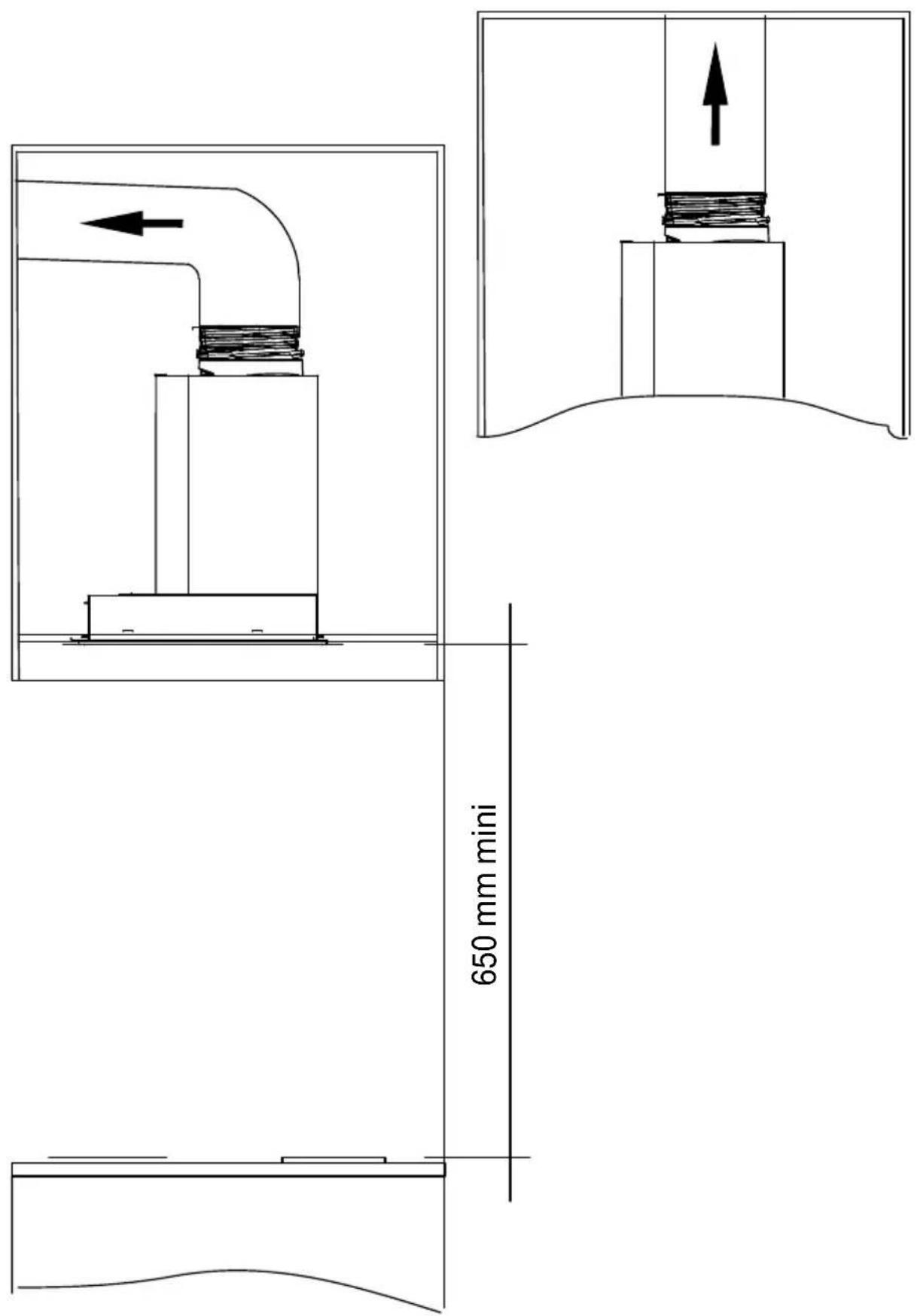
- The Hood can be fitted onto the lower surface of the wall furniture. (650 mm min. from the surface of the cooking appliance to the underside of the cooker hood.)
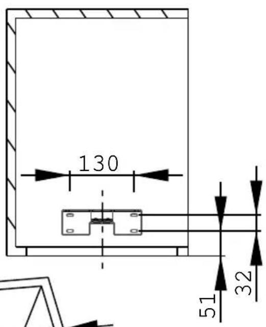
- To carry out a cutting (embedding) on the lower surface of the wall furniture, as indicated.
- To drill the outlet onto the top or the back of the wall furniture.
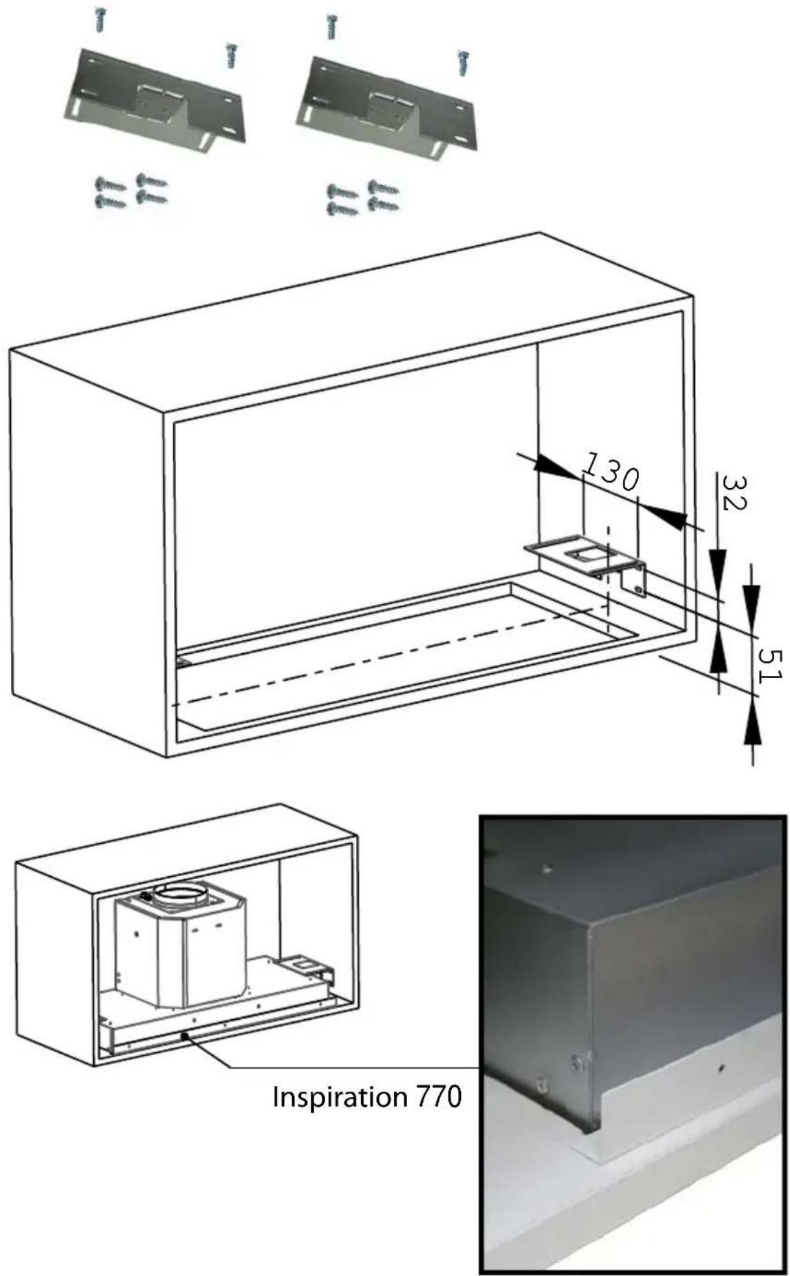
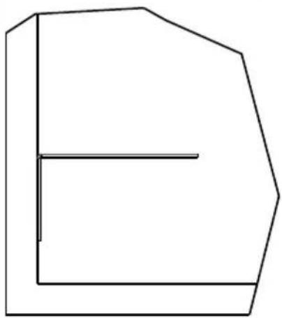
- To fix the 2 squares using the provided screws.
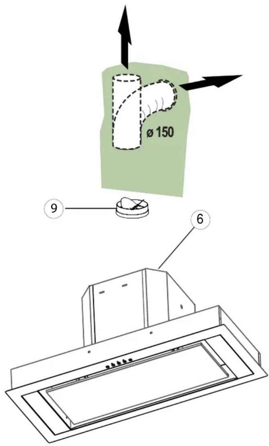
- To place the anti-backflowflats item 9 over the round outlet. To secure the connections with appropriate clamping rings or adhesive tape.
- To place the hood into the embedding and fit it on the 2 squares using the 4 screws supplied.
- DUCTING
The hood is more effective when used in the extraction mode (ducted to the outside). When the cooker hood is ducted to the outside, charcoal filters are not required.
The ducting used must be 150 mm (6 INS), rigid circular pipe and must be manufactured from fire retardant material, produced to BS.476 or DIN 4102-B1. Wherever possible utilise rigid circular pipe which has a smooth interior, rather than the expanding concertina type ducting.
Maximum length of ducting run:
- 4 metres with 1 x 90° bend.
- 3 metres with 2 x 90° bends.
- 2 metres with 3 × 90^ bends.
The above assumes our 150 mm (6 INS) ducting is being installed. Please note ducting components and ducting kits are optional accessories and have to be ordered, they are not automatically supplied with the chimney hood.
- In the extraction mode:
- To connect the round outlet of the hood via a rigid or flexible duct of 150 mm.
- To secure the connections with appropriate clamping rings or adhesive tape not provided.
-
To remove the possible charcoal filte.
-
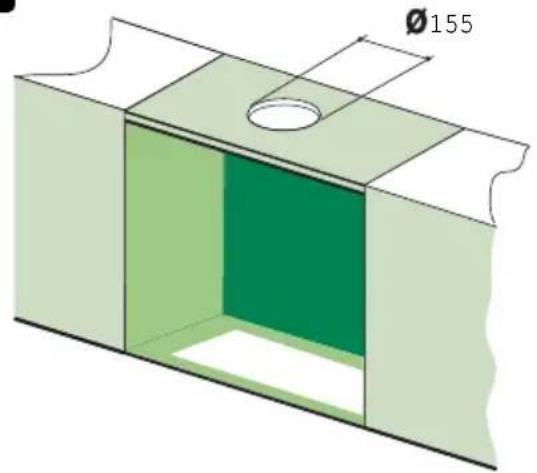
In the recirculation mode: The filtered air is evacuated in kitchen through an outlet placed on the top of furniture or the hood.
- To drill a hole of 155 mm on the top of furniture.
- To connect the round outlet of the hood via a rigid or flexible duct of 150 mm to the outlet on the top of
the furniture.
- To secure the connections with appropriate clamping rings or adhesive tape not provided.
• To Install the charcoal filters inside the canopy.
- The hood can be connected to the mains supply via a double-pole switch having 3mm minimum contact gap on each pole.
4 OPERATION
text_image
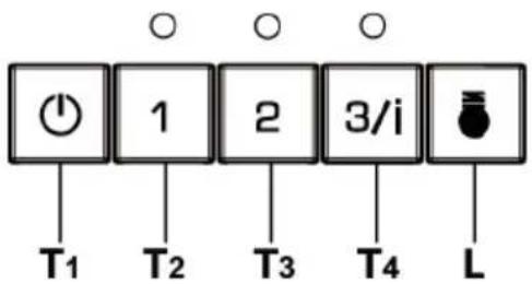
T1 T2 T3 T4 L 1 2 3/iControl panel
| BUTTON | LED | FUNCTIONS |
| T1 Motor | Turns the motor off. | |
| T2 Speed | On | Turns the Motor on at Speed one. |
| T3 Speed | On | Turns the Motor on at Speed two. |
| T4 Speed | Fixed | When pressed briefly, turns the Motor on at Speed three. |
| Flashing | Pressed for 2 Seconds. | |
| Activates Speed four with a timer set to 10 minutes, after which it returns to the speed that was set previously. Suitable to deal with the highest level of cooking fumes. | ||
| L Light | Turns the Lighting System on and off. |
5 USEFUL HINTS
- To obtain the best performance we recommend you to switch 'ON' the cooker hood a few minutes (in the boost setting) before you start cooking and you should leave it running for approximately 15 minutes after finishing.
• IMPORTANT: NEVER DO FLAMBÉ COOKING UNDER THIS COOKER HOOD - Do not leave frying pans unattended during use as over-heated fat and oil might catch fire.
- Do not leave naked flames under this cooker hood.
- Switch 'OFF' the electric and gas before removing pots and pans.
- Ensure heating areas on your hotplate are covered with pots and pans when using the hotplate and cooker hood simultaneously.
6 MAINTENANCE
Before carrying out any maintenance or cleaning isolate the cooker hood from the mains supply. The cooker hood must be kept clean; a build up of fat or grease may cause a fire hazard.
Casing
- Wipe the cooker hood frequently with a clean cloth, which has been immersed in warm water containing a mild detergent and wrung out.
- Never use excessive amounts of water when cleaning particularly around the control panel.
- Never use scouring pads or abrasive cleaners.
• Always wear protective gloves when cleaning the cooker hood.
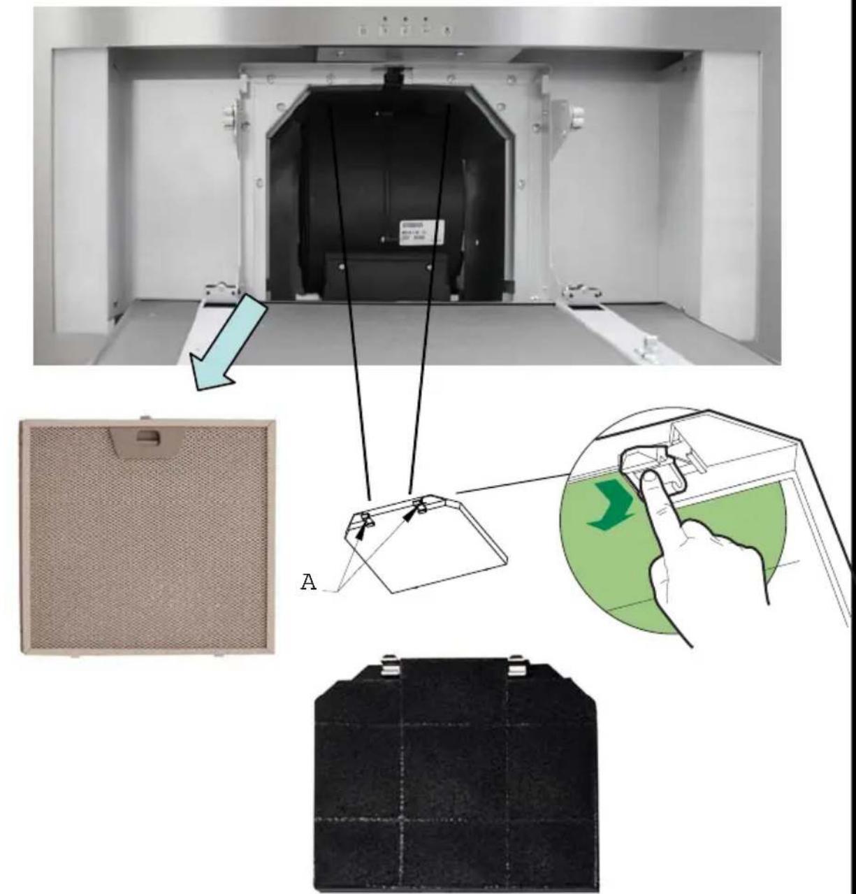
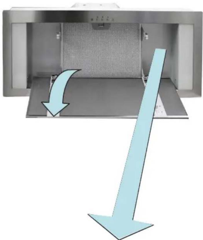
Metal Grease Filters : The metal grease filters absorb grease and dust during cooking in order to keep clean the cooker hood inside. The grease filters should be cleaned once a month or more frequently if the hood is used for more than 3 hours per day.
To remove and replace the metal grease filters
- Remove the metal grease filters one at a time by releasing the catches on the filters; the filters can now be removed.
- The metal grease filters should be washed, by hand, in mild soapy water or in a dishwasher.
- Allow to dry before replacing.
Active Charcoal Filter : The charcoal filter cannot be cleaned. The filter should be replaced at least every three months or more frequently if the hood is used for more than three hours per day.
To remove and replace the filter
- Remove the metal grease filters.
- Press against the two retaining clips, which hold the charcoal filter in place and this will allow the filter to drop down and be removed.
- Clean the surrounding area and metal grease filters as directed above.
- Insert the replacement filter and ensure the two retaining clips are correctly located.
- Replace the metal grease filters.
Extraction tube : Check every 6 months that the dirty air is being extracted correctly. Comply with local rules and regulations with regard to the extraction of ventilated air.
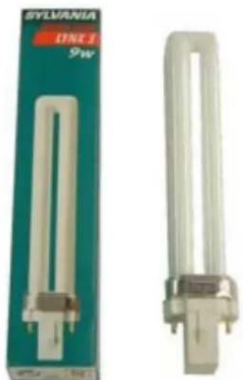
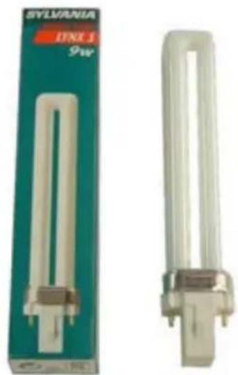
Lighting : If the lamp fails to function check to ensure it is fitted correctly into the holder. If lamp failure has occurred then it should be replaced with identical replacement.
Do not replace with any other type of lamp and do not fit a lamp with a higher rating.
Remote control handset : Caution, the remote control handset must be fitted with standard LR03-AAA size 1.5V zinc-carbon alkaline batteries. These batteries should give a long life and constant discharge throughout their life. These batteries must be disposed of properly and could explode if damaged or exposed to heat. Do not dispose of on fire. Dispose of batteries in the appropriate sort
7 GUARANTEE AND AFTER SALES SERVICE
- In the event of any malfunction or anomaly, notify your fitter who will have to check the appliance and its connection.
- In the event of damage to the mains supply cable, this can only be replaced by at approved repair centre appointed by the manufacturer who will have the required tools and equipment to carry out any repairs properly. Repairs carried out by other persons will invalidate the guarantee.
- Use only genuine spare parts. Should these warnings fail to be observed it could affect the safety of your cooker hood.
- When ordering spare parts quote the model number and serial number written on the rating plate, which is found on the casing behind the grease filters inside the hood.
• Proof of purchase will be required when requesting service. Therefore, please have your receipt available when requesting service as this constitutes the date from which your guarantee commenced.
This Guarantee does not cover :
- Damage or calls resulting from transportation, improper use or neglect, the replacement of any light bulbs or filters or removable parts of glass or plastic.
These items are considered to be consumable under the terms of this guarantee.
8 REMARKS
This appliance complies with European regulations on low voltages Directive 2006/95/CE on electrical safety, and with the following European regulations: Directive 2004/108/CE on electromagnetic compatibility and Directive 93/68 on EC marking.
When this crossed-out wheeled bin symbol ↗ is attached to a product it means the product is covered by the European directive 2002/96/EC. Your product is designed and manufactured with high quality materials and components, which can be recycled and reused. Please inform yourself about the local separate collection system for electrical and electronic product. Please act according to your local rules and do not dispose of your old products with your normal household waste. The correct disposal of your old product will help prevent potential negative consequences for the environment and human health.
text_image
T1 T2 T3 T4 L 1 2 3/iSchalttafel
text_image
T1 1 2 3/i LQuadro comandi
text_image
T₁ 1 2 3/i LTablero de mandos
3 INSTALLATIE VAN HET APPARAAT
text_image
T1 1 2 3/i LBedieningspaneel
natural_image
Simple line drawing of a wind turbine with four circular holes and a central vertical shaft (no text or symbols)3
natural_image
3D diagram of a rectangular chamber with a central green section and a circular hole, showing no text or symbols.2
text_image
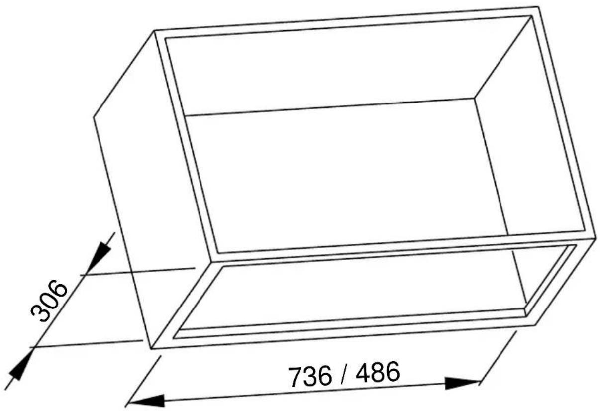
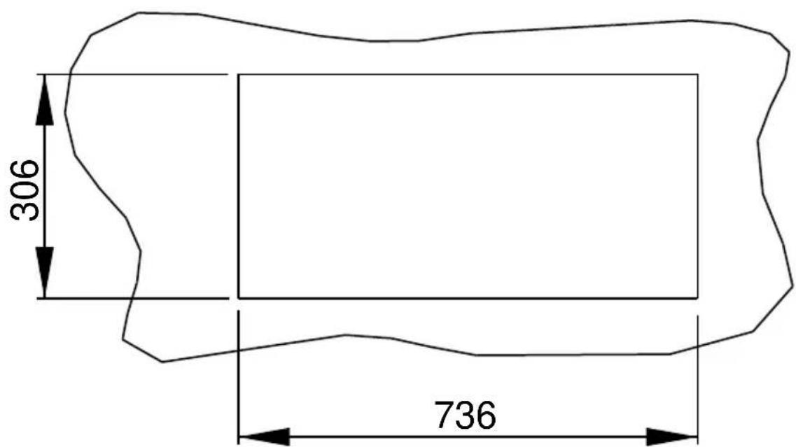
306 736 / 4864
5
natural_image
Pure geometric diagram of a 3D octagonal frame with an internal diagonal line and small rectangular elements (no text or symbols)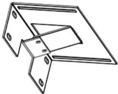
natural_image
Technical line drawing of a mechanical bracket or bracket assembly (no text or symbols)L = 900 mm
natural_image
Pure geometric line drawing of a 3D shape with no text, numbers, or symbols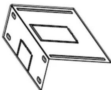
natural_image
Line drawing of a 3D rectangular metal bracket with mounting holes and a slot (no text or symbols)L = 800 mm
text_image
130 51 32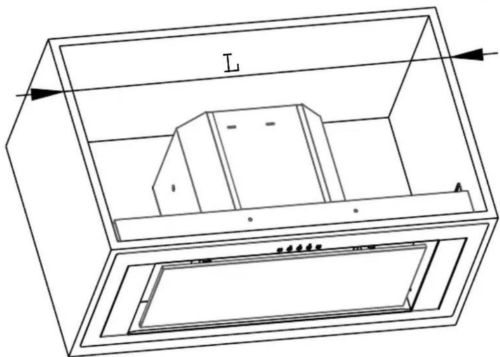
text_image
LInspiration 770
text_image
306 736Inspiration 520
text_image
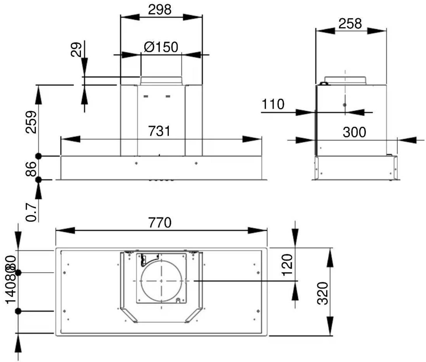
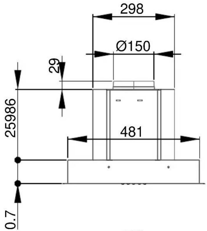
298 Ø150 29 25986 481 0.7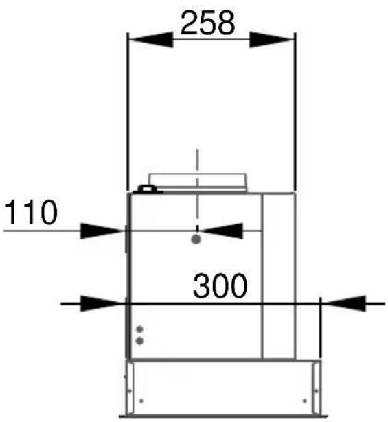
text_image
258 110 300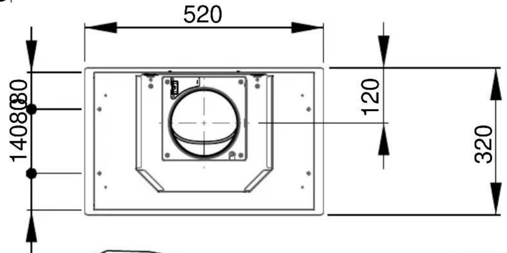
text_image
520 140880 120 320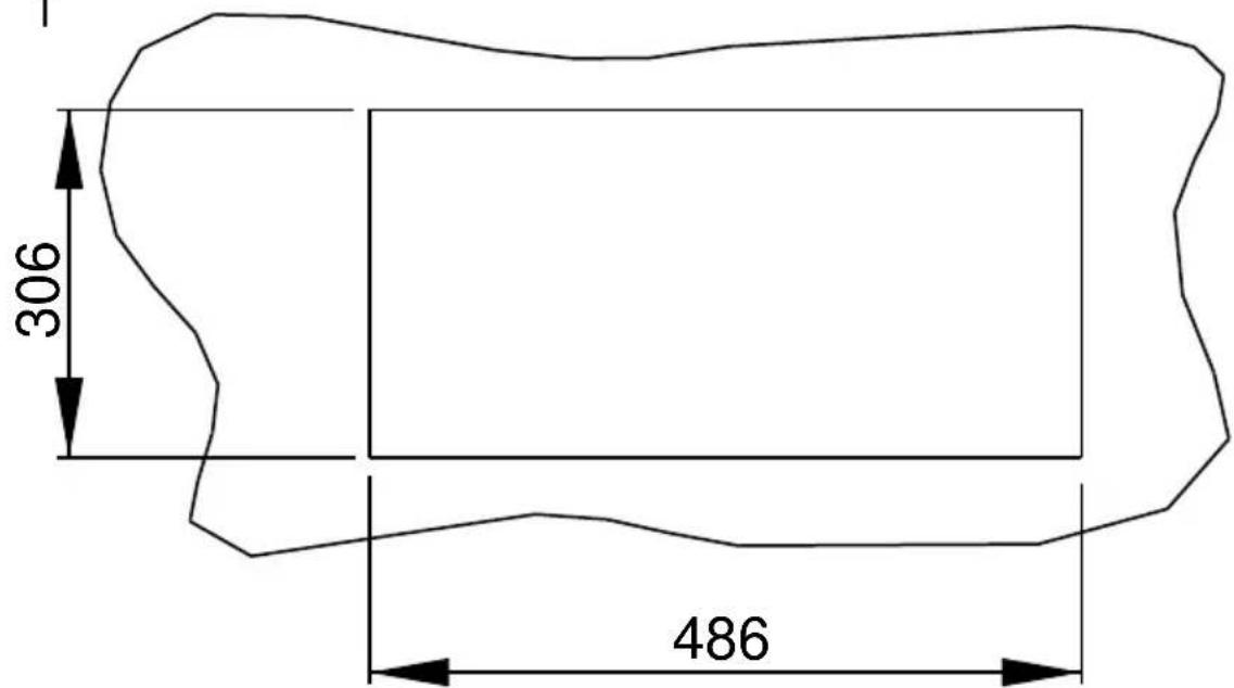
text_image
306 4866
text_image
Ø 150 ⑨ ⑥7
natural_image
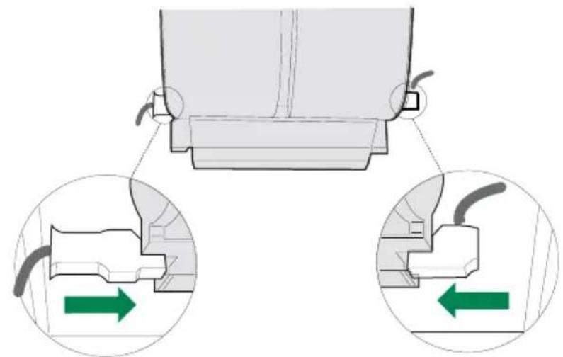
Mechanical component diagram showing two views of a housing with green directional arrows indicating movement or force (no text or symbols present)8
text_image
Technical diagram illustrating a mechanical assembly with labeled components and directional arrows, including a component labeled 'A'.9
A defective light is cutting off the second one's. In this case, you have to change the two lights.
natural_image
Interior view of a metallic enclosure or cabinet with a black arrow pointing to a component (no visible text or symbols)12EC003
natural_image
Two fluorescent light bulbs, one labeled 'SYLVANIA LINE 3 9w', shown against a green and white background (no additional text or symbols visible)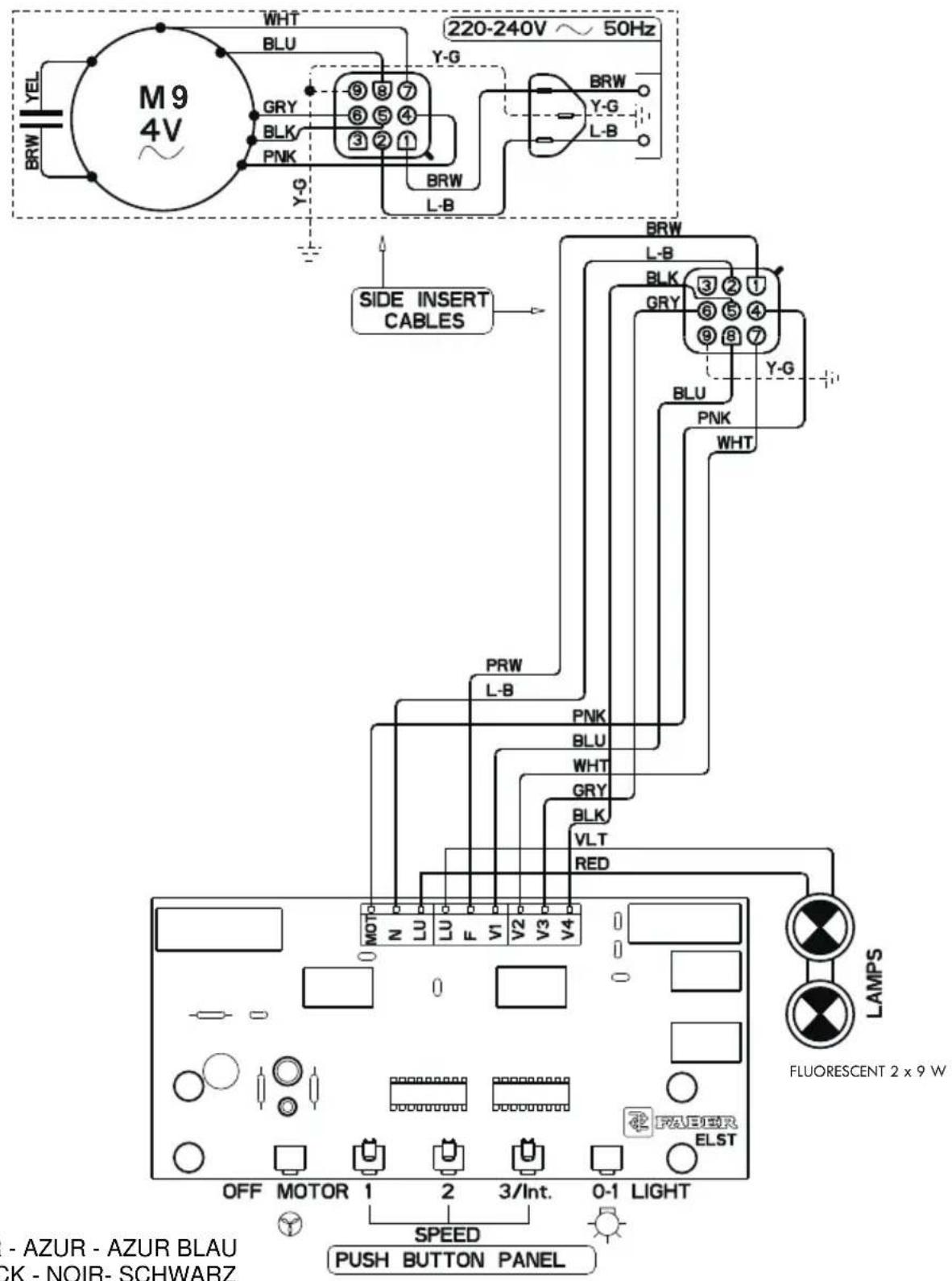
text_image
M9 4V WHT BLU GRY BLK PNK ⑨⑧⑦ ⑥⑤④ ③②① Y-G BRW L-B 220-240V ~ 50Hz BRW Y-G L-B SIDE INSERT CABLES BRW L-B BLK GRY ③②① ⑥⑤④ ⑨⑧⑦ Y-G BLU PNK WHT PRW L-B PNK BLU WHT GRY BLK VLT RED MOTN L1 L2 F V1 V2 V3 V4 OFF MOTOR 1 2 3/Int. 0-1 LIGHT SPEED PUSH BUTTON PANEL FLUORESCENT 2 x 9 W LAMPS - AZUR - AZUR BLAU CK - NOIR- SCHWARZA - AZUR - AZUR - AZUR BLAU
BK - BLACK - NOIR- SCHWARZ
B - BLUE - BLEU - BLAU
Br - BROWN - BRUN - BRAUN
G-Y - GREEN YELLOW - VERT JAUNE - GRÜN GELB
Gr - GREY - GRIS - GRAU
L B - LIGHT BLUE - BLEU CLAIR - HELL BLAU
P - PINK - ROSE - ROSA
V - PURPLE - MAUVE - MALVER FARBIG
R - RED - ROUGE - ROT
W - WHITE - BLANC - WEISS
W-P - WHITE PINK - BLANC ROSE - WEISS ROSA
Y - YELLOW - JAUNE - GELB
Roblin
MAJ (UPDATE) : 10/03/01
UK ELECTRICAL CONNECTION ELECTRICAL REQUIREMENTS
Any permanent electrical installation must comply with the latest I.E.E. Regulations and local Electricity Board regulations. For your own safety this should be undertaken by a qualified electrician e.g. your local Electricity Board, or a contractor who is on the roll of the National Inspection Council for Electrical Installation Contracting (NICEIC).
ELECTRICAL CONNECTION
Before connecting to the mains supply ensure that the mains voltage corresponds to the voltage on the rating plate inside the cooker hood.
This appliance is fitted with a 2 core mains cable and must be permanently connected to the electricity supply via a double-pole switch having 3mm minimum contact gap on each pole. A Switched Fuse Connection Unit to the terminal which is marked with the letter 'N' or coloured black.
to BS.1363 Part 4, fitted with a 3 Amp fuse, is a recommendedmains supply connection accessory ensure compliance with the Safety Requirements applicable to fixed wiring instructions.
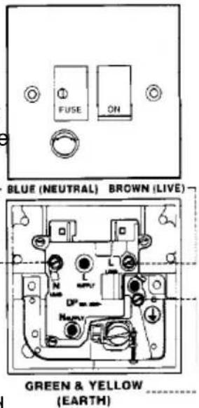
text_image
FUSE ON BLUE (NEUTRAL) BROWN (LIVE) N L MPPT DP NaPV GREEN & YELLOW (EARTH)The wires in this mains lead are coloured in accordance with the following code: Green & Yellow Earth Blue Neutral Brown Live
As the colours of the wires in the mains lead of this appliance may not correspond with the coloured markings identifying the terminals in your connection unit, proceed as follows:-
The wire which is coloured blue must be connected to the terminal which is marked with the letter 'N' or coloured black.
The wire which is coloured brown must be connected to the terminal which is marked with the letter 'L' or coloured red.
CH
natural_image
Coiled black electrical cable with two terminal leads, no text or symbols visible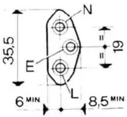
text_image
35,5 E N = 19 6 MIN L 8,5 MIN
text_image
Composants Components Bauelemente Componenti Componentes Onderdelen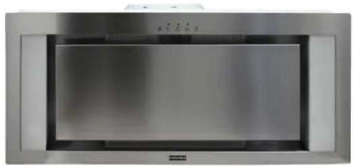
natural_image
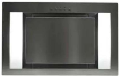
Exterior view of a stainless steel kitchen appliance with open door (no visible text or symbols)13MC070
323 × 262 × 9 mm (×1)
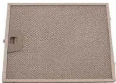
natural_image
Square mesh fan or vent grille with a small rectangular cutout on the left side (no text or symbols visible)INSPIRATION 770
natural_image
Exterior view of a modern office building (no signage)13MC090
262×266×9mm (x1)
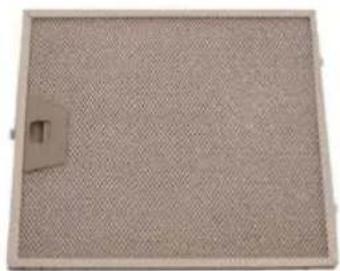
natural_image
Close-up of a mesh fan cover with a small rectangular cutout on the left side (no text or symbols visible)INSPIRATION 520
text_image
Illustration of a stack of documents with visible text lines, likely indicating a list or section
Plaque Signalétique de la hotte Rating plate of the cookerhood Typenschild im Inneren der Dunstesse Etichetta all'interno della cappa Etiqueta de la campana Typeplaatje van de afzuigkap
natural_image
Diagram of a kitchen chimney with a downward arrow indicating airflow or ventilation (no text or symbols present)Modèle
Model
Modell
Modello
Modelo
Model

Numéro de série
Serial number
Seriennummer
Numero di serie
Numero de serie
Serienummer
Roblin
Made in EC
CODE:6208007
MOD: INSPIRATION 770
natural_image
Interior view of a stainless steel kitchen appliance showing structural components and a close-up of the interior panel (no text or symbols visible)ACCESSOIRES ACCESSORIES ZUBEHÖRE
ACCESSORI ACCESORI ACCESSOIRES
12EC003
natural_image
Two white fluorescent lamp bulbs displayed side by side, one labeled 'SYLVANIA LINE 5 9w' (no additional text or symbols visible)
natural_image
Black rectangular battery cell with grid pattern and two metallic clips at top (no visible text or symbols)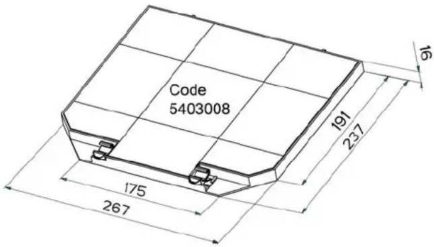
text_image
Code 5403008 191 237 175 267 16Roblin
FRANKE France S.A.S.