
ISLA ARCO - Range hood NODOR - Free user manual and instructions
Find the device manual for free ISLA ARCO NODOR in PDF.
| Brand | Nodor |
| Model | ISLA ARCO |
| Product type | Decorative hood |
| Power supply | 230 V - 50 Hz (check on nameplate) |
| Exhaust duct diameter | 120 mm minimum (rigid PVC recommended) |
| Minimum distance to cooking surface | 65 cm for gas, according to pattern for electric |
| Number of motor speeds | 3 speeds + Turbo |
| Lighting | Halogen lamp with aluminium reflector, adjustable intensity |
| Motor timer function | Yes, cycle up to 20 minutes after stop |
| Programmable alarm | Yes, up to 99 minutes 59 seconds |
| Filter saturation indicator | Yes, after approximately 5000 minutes of operation |
| Built-in clock | Yes, 12h/24h display |
| Grease filter type | Washable (dishwasher or hot water) |
| External cleaning | Non-corrosive liquid detergent |
| Lamp replacement | Disconnect, remove filter, replace with identical lamp |
| Reset function | Yes, press and hold keys and ↑ simultaneously for 3 seconds |
| Electrostatic discharge protection | Restart after turning off/on |
| Maximum number of cooking zones | 4 zones (gas or electric) |
| Electrical connection | Plug or omnipolar switch (contact opening ≥ 3 mm) |
| Certification | Directives 2006/95/EC and 2004/108/EC |
Frequently Asked Questions - ISLA ARCO NODOR
User questions about ISLA ARCO NODOR
0 question about this device. Answer the ones you know or ask your own.
Ask a new question about this device
Download the instructions for your Range hood in PDF format for free! Find your manual ISLA ARCO - NODOR and take your electronic device back in hand. On this page are published all the documents necessary for the use of your device. ISLA ARCO by NODOR.
USER MANUAL ISLA ARCO NODOR
natural_image
Close-up of a stainless steel NODOR air conditioner fan with control buttons (no visible text or symbols beyond branding)E Manual de instalación, uso y mantenimiento de campanas decorativas
D Handbuch zu Installation, Bedienung und Wartung von dekorativen Abzugshauben
F Manuel d'installation, d'utilisation et d'entretien de cloches décoratives
GB Manual for the installation, use and maintenance of decorative hoods
Manuale di installazione, uso e manutenzione di cappa aspirante decorativa
NL Handleiding voor installatie, gebruik en onderhoud van sierafzuigkappen
P Manual de instalação, utilização e manutenção das chaminés extractoras decorativas
DK Installations-, brugs- og vedligeholdelsesvejledning til dekorative emhætter
SF Liesituulettimen kuvun asennus-, käyttö- ja huolto-ohjeet
S Manual för installation, användning och underhåll av dekorativ köksfläkt
NK Installasjons-, bruks- og vedlikeholdsmanual for dekorative hetter
GR Εγχειρίδιο για την τοποθέτηση, χρήση και συντήρηση απορροφητήρων κουζίνας
RUS Инструкция по установке, использованию и уходу за дскоративными вытяжками
PL Instrukcja instalacji, użytkowania i konserwacji okapu dekoracyjnego
H Üzembehelyezési, használati és karbantartási útmutató konyhai szagelszívókhoz
CN 安装及使用手册, 装饰型排油烟机
natural_image
Simple line drawing of a cylindrical object with radiating lines and downward arrows indicating direction (no text or symbols)
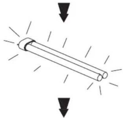
Cambio de los fluorescentes Austausch der Leuchtröhren Changement des fluorescents Changing the fluorescent tubes Sostituzione dei fluorescenti De tl-buizen vervangen Substituição das lâmpadas fluorescentes Udskiftning af lysstofrør Loisteputkilamppujen vaihtaminen Utbyte av lysrör Bytting av lysstoffrør Αλλαγή των λαμπτήρων φθορισμού Смена флуоресцентных ламп Wymiana świetlówek A beépített lámpatestek cseréje
荧光灯管的更换
INDICATIONS GENERALES
We are sure that the purchase of our extractor hood will fully satisfy all of your needs.
Please read this instruction manual carefully in order to obtain the best results from the use of the hood.
INSTRUCTIONS FOR INSTALLATION, MAINTENANCE AND USE
If you need any technical help or would like more information about our products, please do not hesitate to contact our official distributor.
GENERAL INDICATIONS
Before installing and using the hood, be sure that the voltage (V) and the frequency (Hz) indicated on the feature plate match the voltage and frequency at the installation site.
The feature plate and technical data are shown on the inside of the product.
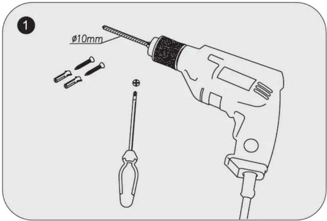
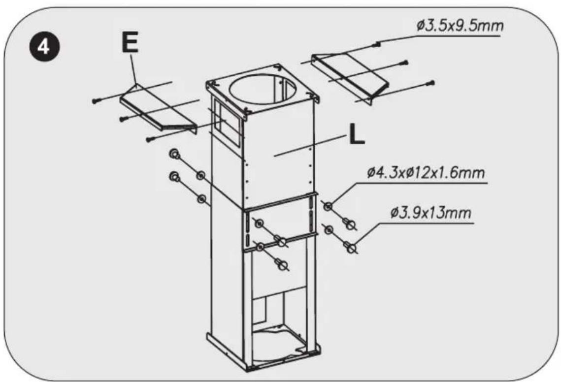
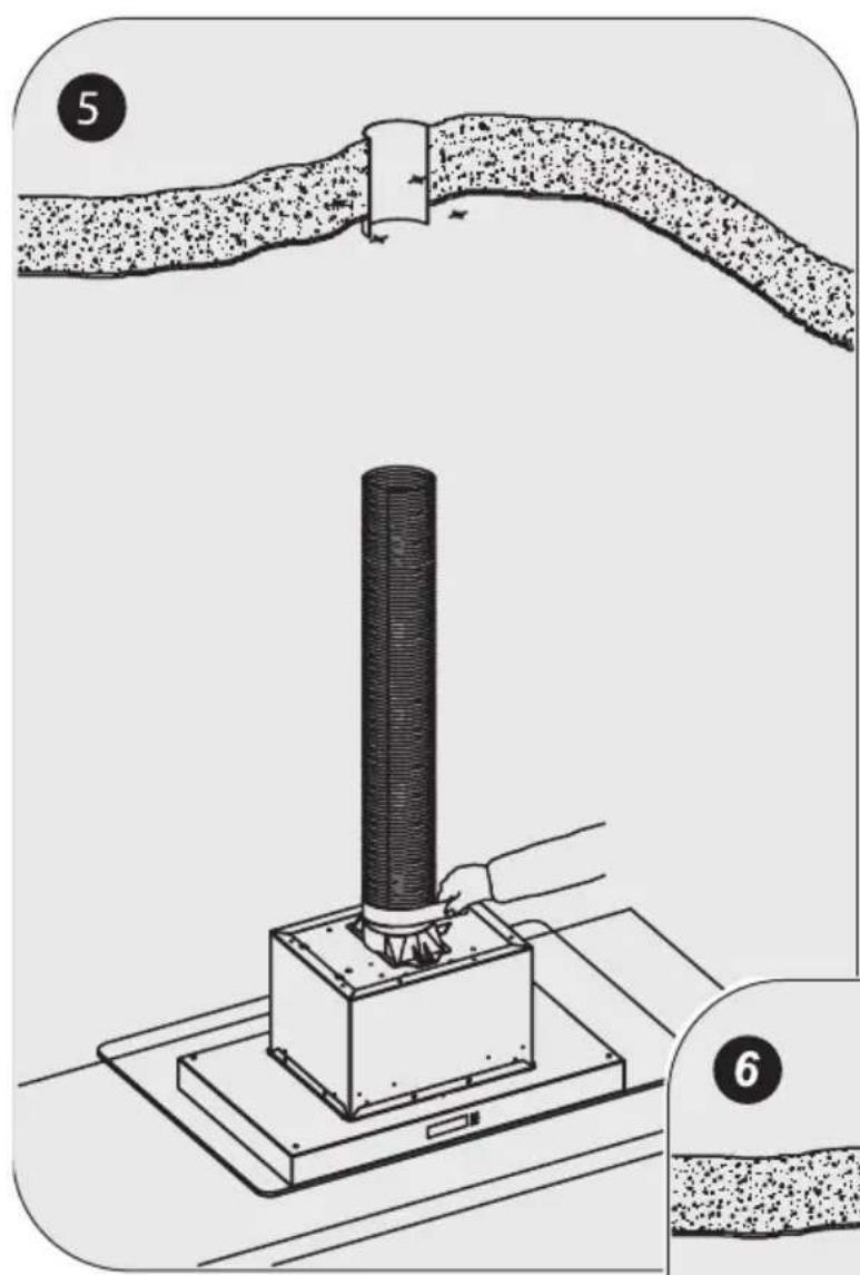
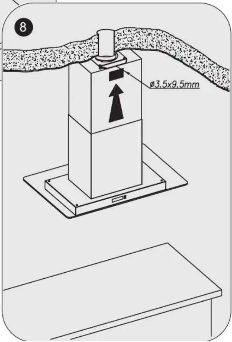
For better performance in extracting fumes we advise that tubing installed should be of a diameter not less than 120 mm. We also advise using rigid PVC tubing.
ELECTRICAL CONNECTION
Connect the cord to a socket or double pole switch, which must have a minimum contact opening distance of 3 mm.
The manufacturer shall not be liable for failure to observe all safety regulations in force for the correct and normal operation of electrical parts.
1- FUNCTION OR PROGRAMMING BUTTON ↗.
With the bell completely off, press for 3 seconds and select the different programming buttons in sequence (time, light and speeds). The corresponding icon will light up according to the function selected.
The sections described below show the system for programming the default values.
In the event of a fault with the power supply, the device will store the programmed speed and light information as the default but the clock will be deactivated.
a.- SETTING THE TIME. If you press the ⬆ key just once for 3 seconds, the time icon lights up. The clock digits should flash and using the ↑ and ↓ you should be able to regulate the time.
The default setting is that the un-programmed time will flash. At the start, the clock is in 24:H mode and by using the ↑ or ↓ keys you can select 24H or 12H. If you select 24h, the AM or PM indicators will not light up. After 2 seconds, if you have not pressed any key the time digits will flash allowing you to select the exact time.
If you keep the ↑ or keys pressed for more than 2 seconds, the time change speed increases. When you press the ➤ button again, it should be adjusted and it will go to the next function. The programming deactivates if you wait 20 seconds.
b.- SELECTING THE LIGHT PROGRAMMING. If you press the ➤ key again in programming mode, the time icon will go off and the light icon ⚙ will come on. You can programme the brightness you want when you switch on the lights. Maximum brightness will be the default. To select the brightness, press the ↑ or ↓ keys. If you wait 20 seconds, the programming will be deactivated.
c.- SELECTING THE DEFAULT SPEED. If you press the ⚡ key again in programming mode, the light icon ⚡ will go off ⚡ and the motor icon will light up. You can also programme the speed that you want and that it comes on by default every time the bell is switch on. The first speed will be the default. To select the speed, press the ⚠ and ⚡ keys. To complete the programming, press the programming key ⚡, or if you wait 20 seconds the programming will be deactivated.
2.- START/STOP BUTTON ⏻. It starts in the speed that you have programmed (the first speed is the default) and the corresponding rectangles will light up. If you press the button again, the motor will stop.
If neither the bell, extractor nor the light function, the display light will dim.
3.- LIGHT ACTIVATION/DEACTIVATION BUTTON
When you switch the light on, it will be activated at the same brightness that you have programmed in the programming function. The ↑ and keys are active and the brightness can be adjusted temporarily until the light is switched off. When you turn it back on, it will have the brightness that you programmed initially.
The light function deactivates after 20 second and returns to the motor position.

4 ALARM BUTTON . SELECTING AND PROGRAMMING
THE ALARM. When you select this option, the alarm icon comes on. The alarm should also flash 00:00. To adjust the alarm, press the ↑ and keys. The upper time limit is 99:59 minutes. If you keep pressing the ↑ or keys for more than 2 seconds, the alarm time change speed increases. After 5 seconds of not pressing any key, the bell symbol stops flashing and the countdown starts. When the alarm is activated, the symbol flashes and the audio warning is activated. Press any key to deactivate the alarm and this function will automatically be deactivated and then return to the status where it was before the function was activated. If you do not press any key, after 5 minutes the bell will stop in all options, with the bell symbol flashing. This flashing can be stopped by pressing any key.
5.- INCREASE ↑ OR DECREASE BUTTONS. A multi-function button:
The type of function that can be carried out by pressing these keys, will be the function that does not flash on the display. All functions that flash on-screen mean that they are activated functions but that their properties cannot be varied.
- Motor function. Default function. When the speed increases or decreases the bars on the screen come on or switch off. When the third speed is increased, the Turbo symbol comes on.
- Light Function. This should be adjusted using the ↑ or ↓ keys.
- Time Function. This is described in the function section.
- Alarm Function. This is described in the function section.
6. MOTOR FUNCTION TIMING BUTTON ↗.
This function only works when the motor is on.
When you press this function, the ⚠ symbol comes on and the speed bar flashes, which is activated at the time. The current speed is maintained for 5 minutes and when it ends the lower speed is activated for a further 5 minutes. This pattern continues until the speeds have ended. It will take 20 minutes at most. When the timing is complete, the motor will stop and so will the lights, if they were on.
7- RESET FUNCTION.
If you need to reset the whole circuit, press the ⏻, and ↓ keys simultaneously for 3 seconds. When the beep sounds, the system will restart.
8- DIRTY FILTERS FUNCTION
There should be a motor function counter to ensure that after approximately 5,000 minutes the wash filter symbol lights up.
When the alarm is activated, the cleaning symbol flashes and the audio level will be activated three times. To deactivate the alarm, press the ↑ and keys simultaneously for 3 seconds until you hear the beep. This function will automatically deactivate and the on counter will be restarted.
If you ignore the cleaning alarm, it will reactivate every time you turn the motor on.
IMPORTANT:
- Do not connect the hood to chimneys, ventilation pipes or hot air pipes. Before connecting any pipes, consult municipal ordinances on exhaust air and request permission from the person in charge of the building. Be sure there is adequate ventilation, even in cases where the hood is to be used simultaneously with another product.
- Never leave frying food unattended since grease can overheat and catch fire. The risk of fire is even greater in the case of used oil.
- Never use the hood in areas where devices with exhaust pipes connected to the outside are already operating unless perfect ventilation can be guaranteed.
- To avoid the possibility of fire, adhere strictly to all of the recommendations included here and to the periodic cleaning of the grease filters.
- During an electrostatic discharge (ESD) it is possible that the device will stop working. By switching the device OFF an ON the device will again work as intended. There is no risk and no risk will appear.
-
If the supply cord of this equipment is damaged, it must only be replaced by manufacturer or its service agent or similarly qualified person in order to avoid a hazard.
-
Never have a lighted flame under the extractor hood.
- The appliance must be placed in such a way, that the supply plug is accessible.
- The hood must be installed at a minimum distance of 65cm from the stovetop.
- During climatic conditions causing electrical interference, it is possible that the device may stop working. By switching the device OFF and ON the device will resume normal operation safety.
- This hood is not designed to be used by people (including children) with reduced physical, sensorial or mental capacity, or who lack experience or knowledge about it, unless they have had supervision or instructions on how to use the hood by someone who is responsible for their safety.
- Children must be supervised to ensure that they do not play with the hood.
- The evacuated air must not be sent along conduits that are used to evacuate smoke from devices powered by gas or other fuels (this does not apply to devices used exclusively to discharge air inside the room).
- When the extractor hood is turned on at the same time as other appliances powered by energy other than electricity, the air outlet must not be greater than 4 Pa (4x10⁻⁵ bar).
- Never use the hood in places where appliances are already operating with outputs connected to the exterior unless perfect ventilation of the place can be ensured.
- This hood can only be installed over electric or gas hobs with a maximum of 4 cooking points.
- If the extractor hood is installed over a gas cooking appliance, the minimum distance between the surface supporting the cooking elements and the lower part of the hood must be at least 65 cm. If the installation instructions for the gas cooker indicate a greater distance, this should be observed.
- If the extractor hood is installed over an electric cooking appliance, the minimum distance to be left between the surface supporting the cooking elements and the lower part of the hood is described in the assembly plan.
- The regulations with respect to air evacuation must be respected.
MAINTENANCE
-Cleaning.
Before any type of operation, always make sure that the electrical cord is disconnected and the switch is in the off position. Clean the external part with a mild, liquid detergent and avoid the use of abrasive cleaning products.
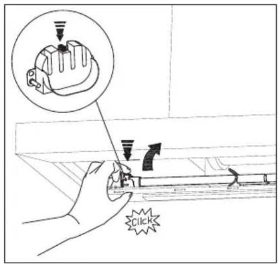
-Changing the light.
Before changing the light make sure that the hood is not connected.
Remove the grease filter and replace the light with a light bulb no more powerful than that specified in the Technical Characteristics. Place the filter in position.
-Cleaning the grease filter.
Depending on use, and at least once a month the grease filters should be disassembled and cleaned in a dishwasher or with hot soapy water.
If washed in a dishwasher, the filters should be placed in an upright position to prevent food remains from falling on them. After rinsing and drying, replace the filters by following the steps for disassembly in reverse order.
The active carbon filters must be replaced periodically to work properly, at least once every three months (depending on the frequency with which the hood is used).
IMPORTANT WARNING FOR EXTRACTOR HOODS WITH HALOGEN LAMPS
If the halogen lamps need replacing, they must be replaced by lamps with an aluminium reflector, never dichroic lamps, to avoid unnecessary overheating in the lamp holders.
THE MANUFACTURER WAIVES ALL LIABILITY FOR FAILURE TO OBSERVE THE INSTRUCTIONS FOR THE APPROPRIATE INSTALLATION, MAINTENANCE AND USE OF THE EXTRACTOR HOOD.
The manufacturer declares that this product meets all the essential requirements for low voltage electrical material set out in European directive 2006/95/EEC of 12 December 2006 and for electromagnetic compatibility as required by European directive 2004/108/EEC of 15 December 2004.
If you need any technical help or would like more information about our products, please do not hesitate to contact our official distributor.
THE MANUFACTURER reserves the right to effect any technological improvement or modification without prior notice.
NODOR
CAPPA ASPIRANTE DECORATIVA
Egregio Cliente,
7- MODALITÀ DI RESET.
1- FUNCTIE OF PROGRAMMA TOETS
6. MOOTTORIN TOIMINNAN AJASTUS
8- FUNKTION FÖR SMUTSIGA FILTER 📋.


- INDICATIONS GENERALES
- INSTRUCTIONS FOR INSTALLATION, MAINTENANCE AND USE
- GENERAL INDICATIONS
- ELECTRICAL CONNECTION
- 1- FUNCTION OR PROGRAMMING BUTTON ↗.
- 3.- LIGHT ACTIVATION/DEACTIVATION BUTTON
- ALARM BUTTON . SELECTING AND PROGRAMMING
- 5.- INCREASE ↑ OR DECREASE BUTTONS. A multi-function button:
- MOTOR FUNCTION TIMING BUTTON ↗.
- 7- RESET FUNCTION.
- 8- DIRTY FILTERS FUNCTION
- IMPORTANT:
- MAINTENANCE
- -Cleaning.
- -Changing the light.
- -Cleaning the grease filter.
- IMPORTANT WARNING FOR EXTRACTOR HOODS WITH HALOGEN LAMPS
- THE MANUFACTURER WAIVES ALL LIABILITY FOR FAILURE TO OBSERVE THE INSTRUCTIONS FOR THE APPROPRIATE INSTALLATION, MAINTENANCE AND USE OF THE EXTRACTOR HOOD.
- NODOR
- CAPPA ASPIRANTE DECORATIVA
- 7- MODALITÀ DI RESET.
- 1- FUNCTIE OF PROGRAMMA TOETS
- MOOTTORIN TOIMINNAN AJASTUS
- 8- FUNKTION FÖR SMUTSIGA FILTER 📋.
Brand : NODOR
Model : ISLA ARCO
Category : Range hood