1922 - Cooker NOVY - Free user manual and instructions
Find the device manual for free 1922 NOVY in PDF.

User questions about 1922 NOVY
0 question about this device. Answer the ones you know or ask your own.
Ask a new question about this device
Download the instructions for your Cooker in PDF format for free! Find your manual 1922 - NOVY and take your electronic device back in hand. On this page are published all the documents necessary for the use of your device. 1922 by NOVY.
USER MANUAL 1922 NOVY
GB: Instructions for use and installations instructions
GB: Table of Contents
Your appliance at a glance 5
GFC 2731
GFC 2732
GFC 2764
GFC 2795
Safety instructions. 9
Installation, connection and function
Operation
Using the appliance. 11
Igniting and adjusting the wok burner
Switching off the wok burner
Igniting and adjusting the wok burner
Switching off the cooking zone
Which are the best pots and pans?
Notes on energy-saving cooking
Cleaning and maintenance 14
All surfaces and parts
Glass ceramic hob
What to do if trouble occurs 15
Assembly and installation 16
Safety instructions
Conditions for building in the appliance
Gas connection
Electrical connection
Installation
Start of operation
Converting to a different type of gas. 25
Replacing the gas nozzles
Technical data. 29
Power, consumption and installation dimensions
Table Permitted gas types and gas pressures
Diameter of injectors
Gas connection schedule
Table Rated load
How you can contribute towards protecting the environment
Directive 2002/96/EC (WEEE): Information for the End User
The following information is directed only at those end users who own products marked, among other things, with the following symbol (Fig. A). This symbol can be found on the label with the technical data for the appliance (rating plate), that is affixed to the appliance:
This symbol means, that under existing regulations, the product is classed as electrical or electronic equipment and must comply with EU Directive 2002/96/EC (WEEE). Therefore, at the end of its serviceable life, the appliance must never be disposed of with your normal household waste. The appliance must be disposed of, either by dropping it off, free of charge, to a designated collection facility for electrical or electronic equipment, or by giving it to a reseller when you purchase a new product.

Fig. A
The end user is responsible for ensuring that the old appliance is disposed of in the proper manner as specified above. Failure to do so is against waste disposal laws currently in force, and could result in prosecution.
Proper separation and collection of old appliances for recycling and the disposal thereof in an environmentally friendly manner helps to protect human health and the environment by allowing components of the appliance to be reused.
For more information about the collection facilities available in your area, please contact your local city council, or the shop where you purchased the appliance.
The manufacturers and importers will meet their responsibility for product recycling and environmentally sound disposal thereof both directly, and by participating in a collection system.
Disposing of the packaging
The packaging serves to protect your appliance from being damaged during transport. We have chosen environmentally-compatible packaging materials that are
easy to dispose of and can hence be recycled. Corrugated board and cardboard are produced mainly from recycled paper.
The styrofoam moulds are free of CFC. Polyethylene (PE) has a proportion of secondary raw materials. The straps are made of polypropylene (PP).
Recycling the packaging material saves on resources and cuts down on waste.
You can generally return the packaging to your retailer.
Please find out where the nearest recycling centre is should you wish to dispose of the packaging material yourself.
Certificate of conformity
We as manufacturers declare that the appliance specified, with the CE no. indicated in the section on "technical data", was constructed in accordance with standard EC-guidelines for gas appliances 90/396/EWG, including adjustments.
The appliance complies with the design specified in the respective EC design test inspection certification.
Your appliance at a glance
GFC 2731
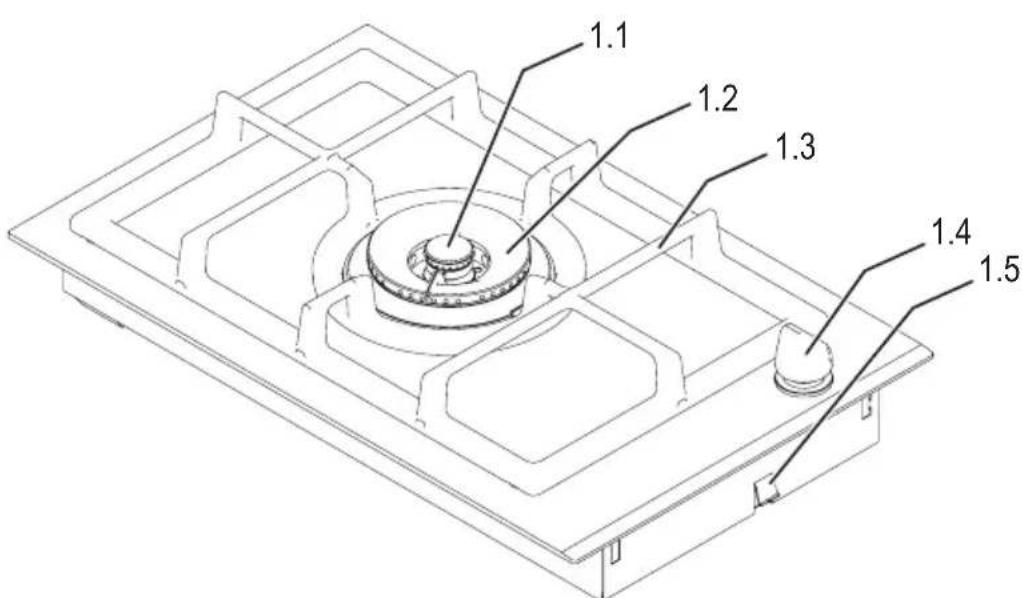
Figure 1
1.1 Inner circuit burner
1.2 Outer circuit burner
1.3 Saucepan support
1.4 Regulator
1.5 Clamps
Gas is connected 1 / 2^ (ISO 7) downwards at the rear in the centre.
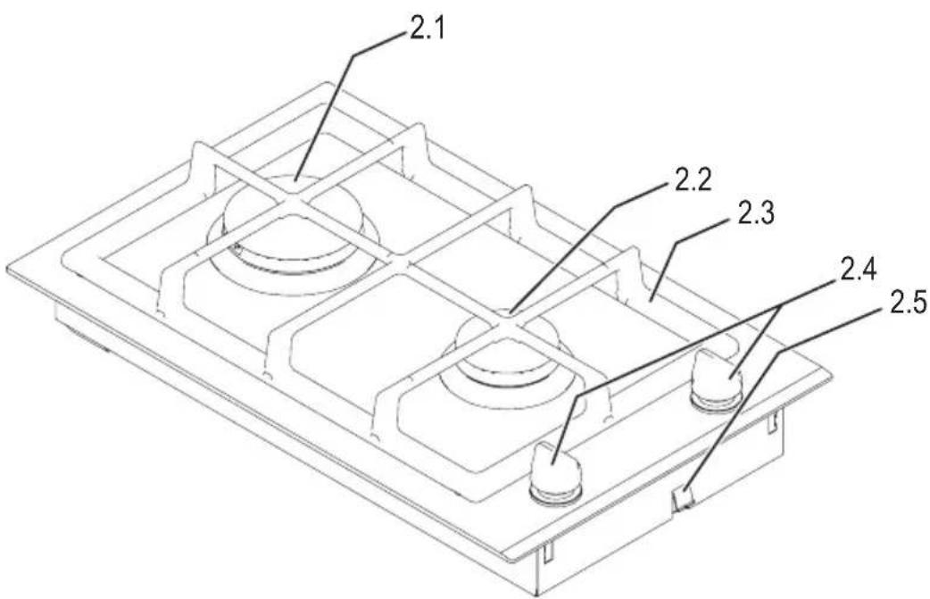
Figure 2
2.1 High speed burner
2.2 Standard burner
2.3 Saucepan support
2.4 Regulator
2.5 Clamps
Gas is connected 1/2 (ISO 7) downwards at the rear in the centre.
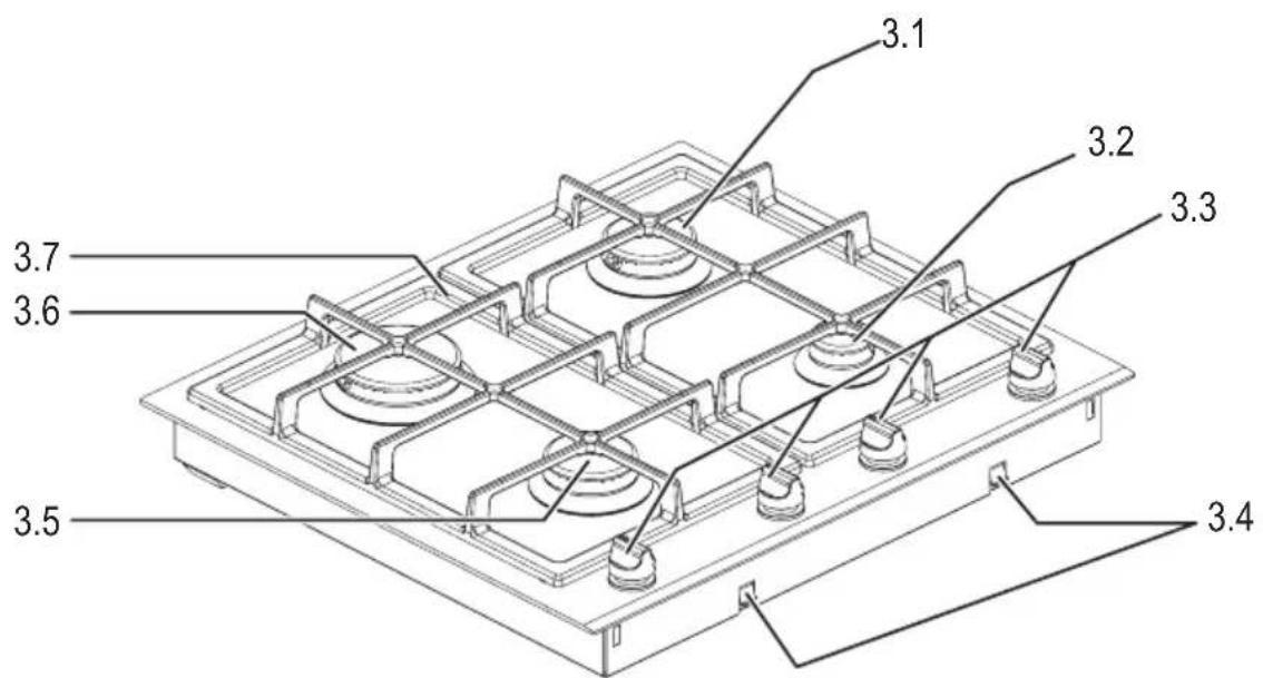
Figure 3
3.1 Standard burner
3.2 Economy burner
3.3 Control knob for cooking zones
3.4 Clamps
3.5 Standard burner
3.6 High speed burner
3.7 2-part pan support
Gas is connected 1 / 2^ (ISO 7) downwards at the rear in the centre.

Figure 4
4.1 Standard burner
4.2 Economy burner
4.3 Control knob for cooking zones
4.4 Clamps
4.5 Standard burner
4.6 High speed burner
4.7 Wok burner
4.8 3-part pan support
Gas is connected 1 / 2'' (ISO 7) downwards at the rear in the centre.
These operating and installation instructions must be discussed with the users and then handed over to them.
- The appliance should only be used with natural gas or liquefied petroleum gas (butane/propane or a mixture of the two).
- This appliance must be installed in accordance with the ruling regulations and may only be used in well ventilated rooms. Please read the instructions before installing and commissioning the appliance.
-
The supply pressure must be
-
for natural gas 2H G20 20 mbar
- for liquified gas 3+ G30 28-30 mbar
G31 37 mbar
Do not take the appliance into operation if the gas supply pressure is out of range.
- natural gas G20 min. 17 mbar, max. 25 mbar
- liquefied gas G30 min. 20 mbar, max. 35 mbar
G31 min. 25 mbar, max. 45 mbar.
- The appliance has been designed for a mains supply of 230V / 50Hz .
- The technical connection data can be found on the rating label of the appliance.
- Before connecting the appliance it must be checked whether the local supply conditions (type of gas and gas pressure) and the settings of the appliance correspond.
- The settings for this appliance are indicated on an indicating label (or on the identification plate). The settings can also be found in these instructions in the section „Technical data" (page 29).
- If a setting is changed, this must be clearly indicated.
- This appliance should not be connected to a pipe for extracting combustion products. It must be installed and connected in accordance with the applicable conditions of installation. Particular attention should be paid to sufficient ventilation measures.
- All work, such as connection to the gas mains or adjusting and converting the appliance, should only be carried out by a qualified gas fitter. The legally recognised regulations and the conditions for connection laid down by the local gas board should be observed in all details.
- All maintenance and repair work should only be carried out by a qualified gas fitter trained by the manufacturer. Always ensure to disconnect the appliance from the energy supply when repairs are being carried out on facilities for directing the flow of gas. Work which has been improperly carried out endangers the safety of the user!
- If the appliance is run on liquefied petroleum gas (butane or propane gas), all connections between the bottle and the appliance must be absolutely tight and leak-proof.
- Do not wedge in freely laid supply hoses or place them on the hot hob.
-
Minimum distance to adjacent wall cupboards hung high above the oven is 650~mm . Please take note of the instructions of the respective manufacturer of the cooker hood.
-
This appliance is not meant to be used by persons (including children) with physical, sensory or mental disabilities, or by persons with insufficient experience of and/or knowledge about its proper use, unless supervised by a person responsible for their safety or following a responsible person's instructions.
- Children should be supervised to ensure that they do not play with this appliance.
- WARNING: If the surface is cracked, disconnect the appliance from the power supply in order to rule out the risk of electric shock.
- The appliances must not be cleaned with a steam cleaner.
- Do not switch the appliance on until the installing gas fitter has explained the appliance to you.
- In addition you should carefully read the information in these operating and installation instructions. Here you will find important notes concerning safety and how to use the appliance. You should remember that any damage due to improper operation does not fall within the scope of the guarantee.
- Only original fittings produced by the manufacturer may be used in order to ensure safe operation of this hob.
- The appliance is designed solely for the preparation of food in the home.
- Never use the appliance to heat a room.
- In the event of any trouble during operation, immediately turn off the supply of gas.
- Please keep this manual in a safe place.
- Make sure that the burner covers are replaced correctly. Engage burner covers by turning.
- Do not switch the burner on if not using it for cooking.
- The surfaces of the hob and of the entire appliance become very hot in use. Always keep children away!
Overheated fats and oils may spontaneously ignite. Food involving the use of fats and oils, e.g. chips, may only be cooked under supervision. Never extinguish ignited fats and oils with water! Put the lid on, turn off the cooking zone and remove the pan. - Always keep pressure cookers under observation until the right pressure has been reached. First turn the burners of the rings up to maximum flame and then (following the instructions of the manufacturer of the pressure cooker) turn the heat down in good time.
- The use of a gas cooker causes heat and humidity to form in the room where the cooker is installed. Always ensure that the kitchen is wellventilated. Keep the natural ventilation openings open or provide a mechanical ventilation device (e.g. fume extractor hood).
- Intensive and prolonged use of the appliance may require additional ventilation, e.g. an open window, or effective ventilation, e.g. operation of the mechanical ventilation device at a higher setting.
Using the appliance

Please note the safety instructions on page 10!

When operating the cooking zones, switch on the cooker hood/extractor fan.
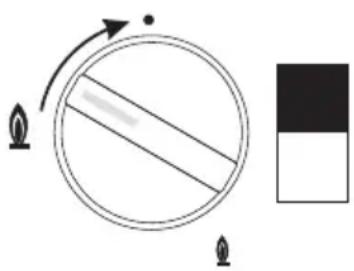
Igniting and adjusting the wok burner
The dual-circuit burner only has one knob for setting all of the functions. The symbols for the individual control positions are arranged in a circle around the control knob.
Control knob positions
1 Closed (OFF)
2 Ignition position
Outer and inner circuit - Full flame
3 Outer circuit - Low flame
4 l n n e r c i r c u i t - F u l l f l·a m Outer circuit, closed
5 l n n e r c i r c u i t - L o w f l a m e
- To ignite the burner, push in the control knob for the cooking zone and turn it anti-clockwise to the "Ignition" (2) position. The Wok burner is ignited automatically by the electric igniter.
- Pres s t h e k n o b f o r approx. 10 seconds.
This is necessary as the gas taps of the appliance are secured thermo electrically. It prevents unburned gas from permanently leaking if a burner goes off.
If the burner has not ignited within 10 seconds, or if the flame has gone out again, stop the ignition attempt. Wait at least a minute before you attempt to ignite the burner again.
- Should there be a power failure or should the spark plugs become damp, escaping gas can also be ignited with a match or with a gas igniter.
- After ignition turn the knob to set the flame as required. The change in the size of the flame between position (4) and (5) is hardly visible. The stability of the flame is limited for the lowest setting (position 5).
- Turning the knob anti-clockwise towards the "inner circuit low flame" (5) mark will reduce the flame.
- turning the knob clockwise towards the "ignition position" (2) mark will make the flame higher.

No settings may be made between the „ignition position" and "OFF".
- Parboil with a high flame and then turn the flame down.
Switching off the wok burner
- To switch off turn the knob clockwise to (1).
Each cooking zone has its own control button. Which control knob belongs to which cooking zone can be seen from the symbols on the control panel.
Example: Knob for the back cooking zone:
The following three symbols are shown beside the control knob for each cooking zone:
0ff

High flame

Low flame
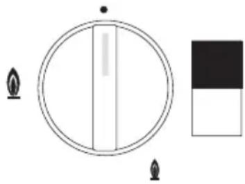
- To ignite the respective burner, push in the control knob for the required cooking zone and turn it to the "high flame" position.
The burner at the cooking zone is automatically ignited by the electric igniter.
- P r e s s t h e k n o b f o r approx. 10 seconds.
This is necessary as the gas taps of the appliance are secured thermo electrically. It prevents unburned gas from permanently leaking if a burner goes off.
If the burner has not ignited within 10 seconds, or if the flame has gone out again, stop the ignition attempt. Wait at least a minute before you attempt to ignite the burner again.
- Should there be a power failure or should the spark plugs become damp, escaping gas can also be ignited with a match or with a gas igniter.
-
After ignition turn the knob to set the flame as required.
-
Turning the knob anti-clockwise towards the "Low flame" mark will reduce the flame.
- Turning the knob clockwise towards the "High flame" mark will make the flame higher.

No settings may be made between the „High flame" and "OFF".
- Parboil with a high flame and then turn the flame down.
Switching off the cooking zone
- To switch off turn the knob clockwise to .
You can save time and power by choosing the best pans.
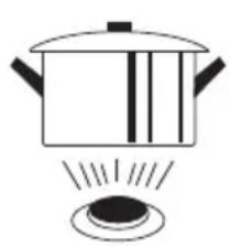
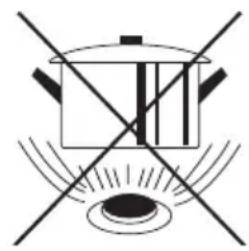
- Use pots and pans with a base that is suitable for the size of the cooking zone: The flames should cover the base of pots and pans but not burn beyond the edge of the cookware base. Heat which flows out around the sides cannot be used and will heat up the handles.
- Since gas flames ensure an optimal transmission of heat from the flame to the base of pats and pans any type of cookware may be used provided it is heat-resistant and suitable for use on flames.
Pots and pans made of stainless steel, aluminium, enamelling and cast iron are ideal, but glassware is also suitable as long as the manufacturer of such cookware expressly permits such use.
- Cookware with a very thin base or bases which are not quite flat is also suitable; this means that you will not need to buy any new special cookware. Sandwich-based cookware is also very suitable; it does, however, not have any advantage over standard cookware.
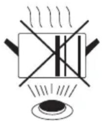
- Never use thin aluminium dishes or plastic vessels!
Pot diameter recommendations:
High speed burner: 22 to 26~cm
Standard burner: 14 to 24~cm
Economy burner: 8 to 16 cm.
Wok burner: 24 to 28 cm.
Notes on energy-saving cooking
- Only cook with very little liquid. The heating of the pot content takes less time and you loose less vitamins and minerals by not pouring away the liquid.
- Always put a well closing lid on the pot. The pot content only boils over if the selected cooking level is too high. If the pot content boils too much switch to a lower cooking level. You need less energy and avoid humidity when cooking.
- Only cook meals as long as necessary. Keeping food warm consumes more energy than warming cooled down food. In addition, you save vitamins: You lose less vitamins because they are not heat resistant.
- When preparing meals with a long cooking time you can save time and energy by using a pressure cooker.
Cleaning and maintenance
All surfaces and parts
. Do not use any a brasive agents and sponges or sharp cleaning agents!
mical oven cleaners, bleaching agents, rust and spot removers can have a corrosive effect and damage the surface of your hob.
- Cleaning agents containing acid or chlorine must not be used.
- Allow surfaces to cool before cleaning.
- Usually it is sufficient to clean the appliance with a damp cloth and a little washing-up liquid each time you use it. Wipe dry afterwards. Always completely remove any remains of cleaning agent with a damp cloth; they could have an corrosive effect.
- Avoid dirt burning and becoming encrusted.
- Take care that the burner covers are replaced correctly after cleaning. Engage burner covers by turning.
Glass ceramic hob
- Before cleaning always wait until the hob has cooled down sufficiently.
Exception: sugar and melted plastic (see below). - Encrusted dirt and food which has boiled over should be removed with a glass scraper. Remove sugar and melted plastic immediately while the cooking surface is still hot.
- Heavy dirt and spots which glitter like mother of pearl can be removed with a cleaning agent for stainless steel.
- Do not use any cleaning cloths or sponges that are used for other purposes. This can discolour the surface, but the discoloration will not become visible the next time you use the appliance.
- To protect and care for the glass ceramic hob we recommend special products to care for glass ceramic hobs such as Ceracle® or Vitroclen®. They protect the hob by covering it with a thin protective film which wards off water and dirt.
What to do if trouble occurs
Replacement may only be carried out by an authorised gas fitter!
First check whether there has been any operating error. You can deal with some problems that occur yourself.
Repairs during the guarantee period are not free of charge, when they are caused by operating errors or non-observation of the following instructions.
Should you need to contact Customer service or order spare parts, always quote the information printed on the model identification plate.
| Fault Cause Remedy | ||
| The cooking zone will not ignite/is out of order. | Blown fuse. Check and replace fuse, | f necessary. |
| Mains plug is non in the wall socket. | Plug the main plug into the wall socket. | |
| Power failure. Cooking zone can be switched on with a match or a lighter. | ||
| No gas supply. Open the gas connection supply. | ||
| Spark igniter damp, clogged or defect. | Clean the spark igniter. If necessary have it replaced.Cooking zone can be switched on with a match or a lighter. | |
| The conductor wire of the spark igniter is broken or the insulator is damaged. | Have the spark igniter replaced.Cooking zone can be switched on with a match or a lighter. | |
| Ignition transformer or switch defect. | Call Customer service.Cooking zone can be switched on with a match or a lighter. | |
| Air in the gas supply line (when putting the appliance into operation for the first time). | Repeat the ignition procedure, several times if necessary. | |
| Burner cover is not lying properly on the burner. | Place the burner cover properly on the burner. | |
| A cooking zone will not switch off. | Cooking zone tap defect. Close the gas connection tap, call Custo-mer service. | |
| Smell of gas in the room. | Leakage in gas supply line or gas connection tap or defective wok bur-ner. | Close the main gas valve,ventilate the room,do not actuate any electric switches,do not ignite any naked flames,notify a qualified gas fitter, your gas supplier, or customer service immediately. |
Assembly and installation
Safety instructions
- This appliance must be installed in accordance with the ruling regulations and may only be used in well ventilated rooms. Please read the instructions before installing and commissioning the appliance.
- Attention! The gas category permitted for the connection of the appliances can differ from region to region. In case of doubt enquire at your local gas board to find out which categories of gas come into question.
- Before connecting the appliance it must be checked whether the local supply conditions (type of gas and gas pressure) and the settings of the appliance correspond. If there are any discrepancies the appliance must be converted accordingly!
- The settings for this appliance are indicated on an indicating label (or on the identification plate). The settings can also be found in these instructions in the section „Technical data" (page 29).
- If the appliance is connected up to the gas mains, particular attention must be paid to the relevant regulations and guidelines laid down by the associations in the country where the appliance is being operated.
Regulations of the local gas utilities and authorities (e.g. for fire protection) are also to be observed.
Statutory regulations and the connection specifications issued by the local power supply company must be strictly observed. - The appliance should only be connected and put into operation by a qualified gas fitter who should also be the only person to carry out any work such as maintenance and repair or adjustment and conversion. The legally recognised regulations and the conditions for connection laid down by the local gas board should be observed in all details.
Work which has been improperly carried out endangers the safety of the user!
- This appliance should not be connected to a pipe for extracting combustion products. It must be installed and connected in accordance with the applicable conditions of installation.
Particular attention should be paid to sufficient ventilation measures. - If the connection plug should not be accessible, protect the appliance by line-protecting switches, fuses or contactors whose contact opening has a width of at least 3mm .
- When the appliance is being connected up and when repair work is being carried out on it, the appliance should be disconnected from the electricity supply using one of these devices. Always ensure to disconnect the appliance from the energy supply when repairs are being carried out on facilities for directing the flow of gas.
- If the power supply cable of this device is damaged, it must be replaced by a special supply cable available from the manufacturer directly or the customer service.
- The earth wire must be sufficiently long so that if the strain relief fails, the live wires of the connecting cable are subjected to tension before the earth wire.
- When converting from natural gas to liquefied petroleum gas, it is always necessary to change the injectors of the wok burner. This also applies if the reverse is the case. This conversion should only be carried out by a qualified gas fitter.
No changes may be made to the appliance unless with the express approval of the manufacturer. - When the appliance has been built in it should not be possible to come into contact with parts that are under electric current.
The installation space must have a minimum volume of 20m^3 and must have a window or door to the outside for ventilation purposes.
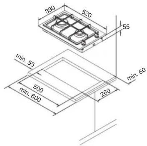
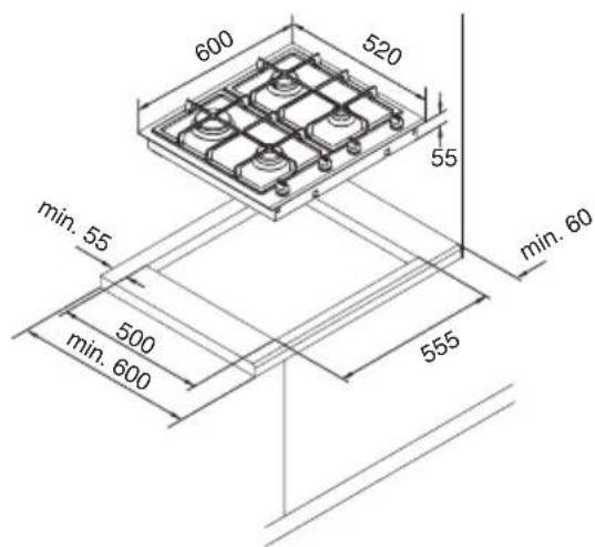
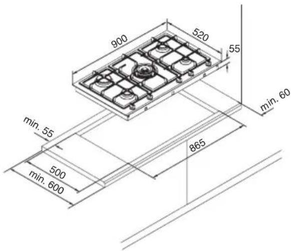
The hob is built into a worktop opening, which must be cut in accordance with the dimensions specified below.
The side clearance between the hob and wall units must be at least 60~mm . However, for practical reasons, a clearance of at least approx. 300~mm should be ensured.
The wall connection strip should be made of heat-resistant material and must not be provided with sockets in the area around the hob. We recommend using a support strip made of plastic and a covering strip made of aluminium. The lateral part on the worktop must not be longer than 30~mm .
The wall above the wall connection strip in the area around the appliance must be made of non-inflammable material. Wood, plastic, PVC foil etc. do not meet this requirement.
Under normal operating conditions heat with a temperature of 65^ above room temperature can radiate onto the surrounding furniture. The furniture parts must at least conform to this requirement.
The plastic finish or the veneer of built-in kitchen furniture must have been produced using a heat-resistant adhesive (100^) .
Minimum distance to adjacent wall cupboards hung high above the oven is 650~mm . Please take note of the instructions of the respective manufacturer of the cooker hood.
The underside of the properly installed hob must be protected by a cover (intermediate bottom or liner) to prevent any accidental contact with the underside of the the hob.
It must only be possible to remove this cover with tools.
When the appliance is fitted and installed, particular attention must be paid to the relevant regulations and guidelines.
First check whether you have the right type of gas and the right gas supply pressure. You will find the details of the gas supply pressure under the heading "Technical data".
The stick-on label indicates what type of gas the built-in hob has been set to run on.
It is possible to convert to another type of gas; this is explained in these operating and installation instructions under "Converting to a different type of gas".
The gas connection must only be done by an approved and qualified gas fitter!
The gas connection at a customer is preferably to be carried out so that it is easily accessible in an adjacent side cabinet.
It must be ensured that the connection parts are laid in such a way that they cannot heat up and become damaged while the appliance is in operation and that they cannot come into contact with the movable parts of the kitchen elements.
Leave the main gas cock closed initially and do not insert the plug into the socket yet.
Electrical connection
An earthed shockproof socket is required for electrical connection. The electrical connection must be carried out in compliance with VDE guidelines and should preferably be in an adjacent cabinet. The appliance has been designed for a mains supply of 230V / 50Hz . For details of electrical power input, please refer to the Technical Data on page 29.
The connection cables must be laid in such a way that they do not heat up and become damaged when the appliance is in operation.
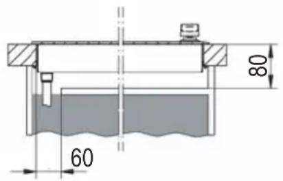
Installation dimensions
The worktop should be between 30mm and 40mm thick. The side clearance between the hob and wall units must be at least 60mm . However, for practical reasons, a clearance of at least approx. 300mm should be ensured.
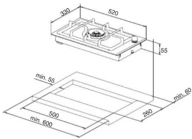
GFC 2731 GFC 2732
GFC 2764 GFC 2795
Preparing for installation
Cut out the worktop recess as accurately as possible according to the measurements provided with a straight saw blade or a surface milling cutter. The cut edges should then be sealed so that no moisture can penetrate.
Model GFC 2731
- Remove the appliance from the packaging.

The individual components are separately packed. Check to ensure that no transport damage has occurred prior to installation.
Installing the appliance
- Prepare the appliance for gas installation according to the instructions on page 18.
- Insert the lower part of the hob into the previously-prepared worktop recess.
- Push the screws (5.1) of all of the clamps (5.2) (for 30mm worktops turn the clamps (5.2)) to the edge of the cut-out and tighten them.
- Remove one of the gaskets (6.7) from the packaging and put it onto the burner (6.9).

Change the jets if necessary (to modify the hob for a different type of gas) prior to mounting the glass-ceramic top.
- Unpack the glass ceramic hob plate. Adhere the sealing strip supplied onto the bottom of the glass-ceramic top plate so that it is flush with the edges.
- Place the glass-ceramic top onto the worktop so that the brackets adhered to the bottom engage in the lower part of the hob.

It is essential that the glass-ceramic top is level on installation: it must be positioned carefully in the area around the burner opening.
- Put the second gasket (6.7) and the clamping ring (6.6) into the opening of the burner. Position the clamping ring so that the holes for the screws lie on the holes for the threads in the burner (6.9).

The clamping ring must be level (it may not be canted)!
- Use the screws supplied to screw the clamping ring (6.6) to the burner (6.9). Tighten the screws evenly.
- Remove the burner components from the packaging and install them one after the other (see illustration), ensuring that they engage as required.
- Take the control knobs (6.8) out of the packaging and snap them on.
Put on the pan supports (6.1).
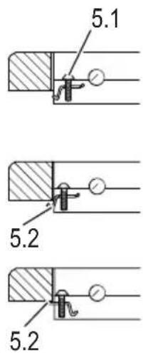
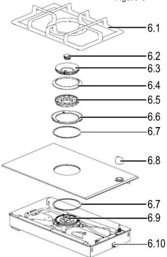
Figure 5
Figure 6
Model GFC 2732
- Remove the appliance from the packaging.

The individual components are separately packed. Check to ensure that no transport damage has occurred prior to installation.
Installing the appliance
- Prepare the appliance for gas installation according to the instructions on page 18.
- Insert the lower part of the hob into the previously-prepared worktop recess.
- Push the screws (5.1) (see page 20) of all of the clamps (5.2) (for 30mm worktops turn the clamps (5.2)) to the edge of the cut-out and tighten them.

Change the jets if necessary (to modify the hob for a different type of gas) prior to mounting the glass-ceramic top.
- Remove the glass-ceramic top plate from the packaging. Adhere the sealing strip supplied onto the bottom of the glass-ceramic top plate so that it is flush with the edges.
- Place the glass-ceramic top onto the worktop so that the brackets adhered to the bottom engage in the lower part of the hob.

It is essential that the glass-ceramic top is level on installation: it must be positioned carefully in the area around the burner opening.
- Put the clamping rings (7.4) with mounted gaskets (7.5) into position, so that the screws holes are aligned with the tapped holes in the burner.

The clamping ring must be level (it may not be canted)!
- Use the screws supplied to screw the clamping ring (7.4) to the burner. Tighten the screws evenly.
- Remove the burner components from the packaging.
- Put on the burner heads (7.3) and then the burner caps (7.2).
Put on the pan supports (7.1). - Take the control knobs out of the packaging and snap them on.
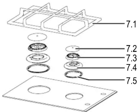
Figure 7
Model GFC 2764

To protect the glass ceramic hob plate during transport, it is delivered mounted to the hob base. Therefore, to install the appliance in the worktop, the glass ceramic hob plate must be taken off first.
- To do that, take the appliance out of its packaging and after unscrewing the fastening screws, remove the clamping rings (8.4) along with the mounted gaskets.
- Carefully put the glass ceramic hob plate down in a suitable place.
- Then install the appliance in the described manner.
Installing the appliance
- Prepare the appliance for gas installation according to the instructions on page 18.
- Insert the lower part of the hob into the previously-prepared worktop recess.
- Push the screws (5.1) (see page 20) of all of the clamps (5.2) (for 30mm worktops turn the clamps (5.2)) to the edge of the cut-out and tighten them.

Change the jets if necessary (to modify the hob for a different type of gas) prior to mounting the glass-ceramic top.
- Adhere the sealing strip supplied onto the bottom of the glass-ceramic top plate so that it is flush with the edges.
- Lay the glass ceramic plate on the worktop.

It is essential that the glass-ceramic top is level on installation: it must be positioned carefully in the area around the burner opening.
- Put the clamping rings (8.4) with the mounted gaskets into position, so that the screws holes are aligned with the tapped holes in the burner.

The clamping ring must be level (it may not be canted)! If the gaskets stick to the glass ceramic hob plate, make sure, when you pull them onto the clamping rings, that the approx. 1.5 cm wide lip of the gasket is properly inserted into the recess in the clamping ring.
- Use the screws supplied to screw the clamping ring to the burner (10.1) (see page 26). Tighten the screws evenly.
- Remove the burner components from the packaging.
- Put on the burner heads (8.3) and then the burner caps (8.2).
Put on the pan supports (8.1). - Take the control knobs (8.6) out of the packaging and snap them on.
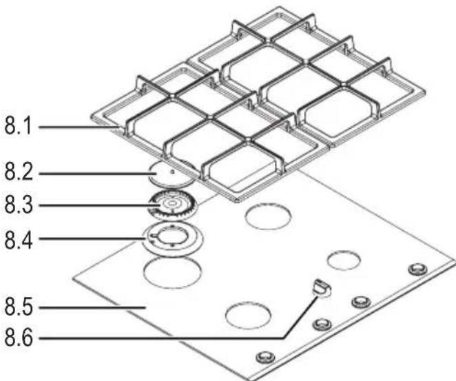
Figure 8
Model GFC 2795

To protect the glass ceramic hob plate during transport, it is delivered mounted to the hob base. Therefore, to install the appliance in the worktop, the glass ceramic hob plate must be taken off first.
- To do so, remove the appliance from the packaging and, after unscrewing the fastening screws, take off the clamping rings (9.10) with mounted gaskets and clamping ring (9.6) with gasket (9.7).
- Carefully put the glass ceramic hob plate down in a suitable place.
- Then install the appliance in the described manner.
Installing the appliance
- Prepare the appliance for gas installation according to the instructions on page 18.
- Insert the lower part of the hob into the previously-prepared worktop recess.
- Push the screws (5.1) (see page 20) of all of the clamps (5.2) (for 30mm worktops turn the clamps (5.2)) to the edge of the cut-out and tighten them.

Change the jets if necessary (to modify the hob for a different type of gas) prior to mounting the glass-ceramic top.
- Remove one of the gaskets (9.7) from the packaging and put it onto the burner (10.1) (see page 26).
- Adhere the sealing strip supplied onto the bottom of the glass-ceramic top plate so that it is flush with the edges.
- Lay the glass ceramic plate on the worktop.

It is essential that the glass-ceramic top is level on installation: it must be positioned carefully in the area around the burner opening.

Figure 9
Wok burner
- Put the second gasket and the clamping ring into the opening of the burner. Position the clamping ring so that the holes for the screws lie on the holes for the threads in the burner.

The clamping ring must be level (it may not be canted)!
- Use the screws supplied to screw the clamping ring to the burner (10.1) (see page 26). Tighten the screws evenly.
- Remove the burner components from the packaging and install them one after the other (see illustration), ensuring that they engage as required.
Standard, High-Speed and Economy Burners
- Put the clamping rings (9.10) with mounted gaskets into position, so that the screws holes are aligned with the tapped holes in the burner.

The clamping rings must lie flat (do not cant)! If the gaskets stick to the glass ceramic hob plate, make sure, when you pull them onto the clamping rings, that the approx. 1.5cm wide lip of the gasket is properly inserted into the recess in the clamping ring.
- Screw the clamping rings to the burners (10.2) with the supplied screws (see page 26). Tighten the screws evenly.
- Remove the burner components from the packaging and install them one after the other (see illustration), ensuring that they engage as required.
- Put the pan supports (9.1) and (9.13) into place.
- Take the control knobs (9.8) out of the packaging and snap them on.
All Models
Making the gas connection
- Make the gas connection according to the information on page 18.
Checking the supply lines
Power supply
- Check the installation of the connection cable.
It must not be pinched in any way, or be lead over the cooker, or lie alongside the exhaust duct.
Gas supply:
The hoses must be installed in such a way that they are at a safe distance from hot surfaces.
The hoses must not be tightly wedged in!
- Insert the plug into an earthed shock-proof socket.
- Open gas connection supply or plug the plug of the gas safety hose into the gas socket.
Before putting the appliance into operation it must be checked by the fitter for perfect functioning and any gas leaks. The appliance is then ready for operation.
The fitter must explain to the operator how to work the appliance on the basis of the instructions for use. These instructions must then be handed over to the user.
Converting to a different type of gas
- If the appliance is converted to run on a different type of gas, this should only be carried out by a qualified gas fitter.
-
All appliances marked with the setting G20 must be operated within Wobbe index range 11.3- 15.2 kWh/ m^3 without changing the setting.
-
If a setting is changed, this must be clearly indicated.
Ensure that injectors with the correct diameter are used! Suitable injectors are indicated on page 30 in the table "Diameter of injectors".
Before doing the conversion, shut off the gas and electricity supply to the appliance.
The following procedures refer specifically to Model GFC 2795.
As the modules of this hob are comparable in setup to the other models, a separate description of the procedures for converting to a different type of gas will not be given for each individual model.
- Remove the control knob.
- Remove the pan supports, the burner caps and the burner heads.
- Then unscrew the screws that secure the clamping rings to the burners.
- Take off the clamping rings along with the gaskets (see Fig. on page 23).
- Lift off the glass ceramic plate.
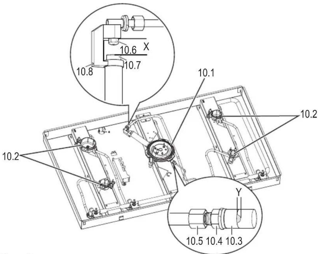
Figure 10
Replacing the main gas nozzles
Standard, High-Speed and Economy Burners
- Exchange the main gas nozzles in the bottom part of the burners (10.2) with socket key.
Wok Burner, Outer Circuit
- Loosen the locking screw (10.8) and push the MS injector (10.7) far enough into the mixing tube until the outer ring nozzle (10.6) is accessible.
Exchange the outer ring nozzle. - Adjust the MS injector until the clearance (X) corresponds with that given in the following table. Re-tighten the locking screw (10.8).
- After exchanging the nozzle, check, for any gas leaks.
| Gas type, Pressures | Outer burner X Inner burner Y | |
| Natural gas G20, 2H 20 mbar | 6 mm | 3/4 open() |
| Liquefied petroleum gas G30/G31, 3+ Butane/propane 28-30/37 mbar | 14 mm | fully open() |
Wok burner, Inner circuit
- Loosen the screw fitting (10.5) (see page 26) and unscrew the nozzle holder (10.4) (see page 26).
- Exchange the inner ring nozzle (11.1).
- Screw the nozzle holder back in and connect it to the feed line.
- Adjust the sliding sleeve (10.3) (see page 26) in accordance with the above table (Y).
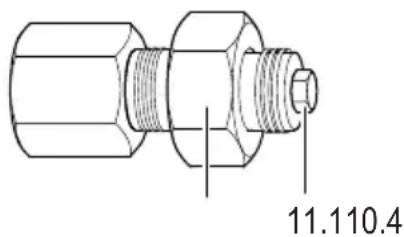
Figure 11
Adjusting the lowest setting

The lowest setting of the wok burner must be adjusted with the ceramic glass plate removed! The appliance may not be re-connected to the mains due to the fact that the electric wiring will then be accessible. Ignite the burner with a match or a gas igniter.
- Re-connect the gas supply.
Wok burner
Put the wok burner rings and caps into place. Make sure that they are positioned correctly!
- Turn the switch sideways, or remove the retaining ring and take off the MS washer, the spring and the switch.
- Unscrew the minimum flame nozzles (12.2) and (12.1) screw the new minimum flame nozzles fully in, as far as they will go. The larger diameter nozzle must be screwed into position (12.2).
- Ignite the cooking zone burner and turn the knob into position "Outer circuit - Low flame", (page 11, item 3).
- Make sure that the flames are not extinguished when the knob is turned from the highest to the setting (page 11, item 3). If this happens the minimum flame nozzle (12.2) can be turned back slightly.
- Then turn the knob into position "Inner circuit - Low flame" (page 11, item 5).
- Make sure that the flames are not extinguished when the knob is turned from the highest to the setting (page 11, item 5). If this happens the minimum flame nozzle (12.1) can be turned back slightly.
- Remove the burner rings and cap of the wok burner again.
- Turn the switch back to its original position, or re-install the switch, spring and MS-washer and secure them with the retaining ring.
- Perform a function test.
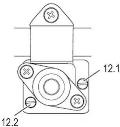
Figure 12
Standard, High-Speed and Economy Burners
- Turn the switch sideways, or remove the retaining ring and then take off the MS washer, the spring and the switch.
- Unscrew the minimum flame nozzle (13.1) and screw in the new minimum flame nozzle fully in, as far as it will go.
- Turn the switch back to its original position, or re-install the switch, spring and MS-washer and secure them with the retaining ring.
- Re-install the hob. To do so, proceed as described in the chapter "Assembly" (pages 20 to 24).
- Perform a function test.
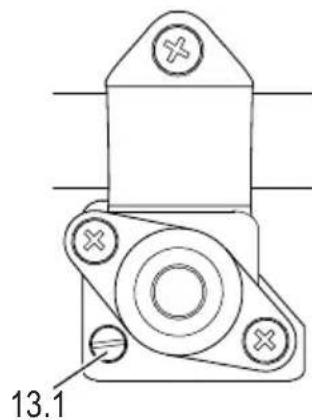
Figure 13
Technical data
Power, consumption and installation dimensions
| GFC 2731 GFC | 2732 GFC 2764 GFC | 2795 | |||
| Burner power based on HS (H) | |||||
| High speed burner | 1 x 3.0 (2.7) kW 1 | x 3.0 (2.7) kW 1 x 3.0 (2.7) kW | |||
| Standard burner | 1 x 1.65 (1.50) kW | 2 x 1.65 (1.50) kW | 2 x 1.65 (1.50) kW | ||
| Economy burner | 1 x 1.0 (0.9) kW 1 | x 1.0 (0.9) kW | |||
| Wok burner | 1 x 5.9 (5.35) kW | 1 x 5.9 (5.35) kW | |||
| Electrical connection | |||||
| Gas (liquified gas) | 5.90 (5.35) kW | 4.65 (4.20) kW | 7.3 (6.60) kW | 13.2 (11.95) kW | |
| Liquefied petroleum gas | 4.28 g/h | 338 g/h | 530 g/h | 958 g/h | |
| Electrical connection, total | 2 W | 2 W | 2 W | 2 W | |
| Appliance dimensions/mm | |||||
| Hob W x D x H | 330 x 520 x 55 | 330 x 520 x 55 | 600 x 520 x 55 | 900 x 520 x 55 | |
| Cutout W x D | 260 x 500 | 260 x 500 | 555 x 500 | 865 x 500 | |
| Appliance category | 3 | 3 | 3 | 3 | |
| Product identification number CE0085 | BQ0415 BQ0415 BQ0415 BQ0415 BQ0415 BQ0415 BQ0415 BQ0415 BQ0415 BQ0415 BQ0415 BQ0415 BQ0415 BQ0415 BQ0415 BQ0415 BQ0415 BQ04 | 15 BQ0415 BQ0415 BQ0415 BQ0415 BQ0415 BQ0415 BQ0415 BQ0415 BQ0415 BQ0415 BQ0415 BQ0415 BQ0415 BQ0415 BQ0415 BQ0415 B0415 B0415 B0415 B0415 B0415 B0415 B0415 B0415 B0415 B0415 B0415 B0415 B0415 B0415 B0415 B0415 B0415 B0415 B0415 B0415 | 15 BQ0415 BQ0415 BQ0415 BQ0415 B0415 B0415 B0415 B0415 B0415 B0415 B0415 B0415 B0415 B0415 B0415 B0415 B0415 B0415 B04 | 15 BQ0415 BQ0415 B0415 B0415 B0415 B0415 B0415 B0415 B0415 B0415 B0415 B0415 B0415 B0415 B0415 B0415 B0415 B0415 B0415 | 15 BQ0415 B0415 B0415 B0415 B0415 B0415 B0415 B0415 B0415 B0415 B0415 B0415 B0415 B0415 B0415 B0415 B0415 B0415 B0415 B15 B0415 B0415 B0415 B0415 B0415 B0415 B0415 B0415 B0415 B0415 B0415 B0415 B0415 B0415 B0415 B0415 B0415 B0415 B0415 B0315 B0315 B0315 B0315 B0315 B0315 B0315 B0315 B0315 B0315 B0315 B0315 B0315 B0315 B0315 B0315 B0315 B0315 B0315 B0315 B0415 B0415 B0415 B0415 B0415 B0415 B0415 B0415 B0415 B0415 B0415 B0415 B0415 B0415 B0415 B0415 B0415 B0415 B0415 B0245 B0245 B0245 B0245 B0245 B0245 B0245 B0245 B0245 B0245 B0245 B0245 B0245 B0245 B0245 B0245 B0245 B0245 B0245 B0245 B0215 B0215 B0215 B0215 B0215 B0215 B0215 B0215 B0215 B0215 B0215 B0215 B0215 B0215 B0215 B0215 B0215 B0215 B0215 B0215 B0225 B0225 B0225 B0225 B0225 B0225 B0225 B0225 B0225 B0225 B0225 B0225 B0225 B0225 B0225 B0225 B0225 B0225 B0225 B0225 B0215 B0215 B0215 B0215 B0215 B0215 B0215 B0215 B0215 B0215 B0215 B0215 B0215 B0215 B0215 B0215 B0215 B0215 B0215 B02 BQ0415 B0245 B0245 B0245 B0245 B0245 B0245 B0245 B0245 B0245 B0245 B0245 B0245 B0245 B0245 B0245 B0245 B0245 B0245 B0245 BQ0415 B0245 B0245 B0245 B0245 B0245 B0245 B0245 B0245 B0245 B0245 B0245 B0245 B0245 B0245 B0245 B0245 B0245 B0245 B0315 B0315 B0315 B0315 B0315 B0315 B0315 B0315 B0315 B0315 B0315 B0315 B0315 B0315 B0315 B0315 B0315 B0315 B0315 B03 BQ0415 B0315 B0315 B0315 B0315 B0315 B0315 B0315 B0315 B0315 B0315 B0315 B0315 B0315 B0315 B0315 B0315 B0315 B0315 B0315 BQ0415 B0315 B0315 B0315 B0315 B0315 B0315 B0315 B0315 B0315 B0315 B0315 B0315 B0315 B0315 B0315 B0315 B0315 B0315 B0215 B0215 B0215 B0215 B0215 B0215 B0215 B0215 B0215 B0215 B0215 B0215 B0215 B0215 B0215 B0215 B0215 B0215 B0215 B0315 B0315 B0315 B0315 B0315 B0315 B0315 B0315 B0315 B0315 B0315 B0315 B0315 B0315 B0315 B0315 B0315 B0315 B0315 B0215 B0315 B0315 B0315 B0315 B0315 B0315 B0315 B0315 B0315 B0315 B0315 B0315 B0315 B0315 B0315 B0315 B0315 B0315 B0215 B08 BQ0415 B0815 B0815 B0815 B0815 B0815 B0815 B0815 B0815 B0815 B0815 B0815 B0815 B0815 B0815 B0815 B0815 B0815 B0815 B0815 B0815 B0315 B0315 B0315 B0315 B0315 B0315 B0315 B0315 B0315 B0315 B0315 B0315 B0315 B0315 B0315 B0315 B0315 B0315 B0315 B08 BQ0415 B0815 B0815 B0815 B0815 B0815 B0815 B0815 B0815 B0815 B0815 B0815 B0815 B0815 B0815 B0815 B0815 B0815 B0315 B0315 B08 BQ0415 B0815 B0815 B0815 B0815 B0815 B0815 B0815 B0815 B0815 B0815 B0815 B0815 B0815 B0815 B0815 B0315 B0315 B08 BQ0415 B0315 B08 BQ0415 B0815 B0815 B0815 B0815 B0815 B0815 B0815 B0815 B0815 B0815 B0815 B0815 B0815 B0815 B0815 B0815 B0315 B0315 B08 BQ0315 B0315 B08 BQ0315 B0315 B08 BQ0315 B0315 B08 BQ0315 B0315 B08 BQ0315 B0315 B08 BQ0315 B0315 B08 BQ0315 B0315 BQ0315 B0315 BQ0315 B0315 BQ0315 BQ0315 BQ0315 BQ0315 BQ0315 BQ0315 BQ0315 BQ0315 BQ0315 BQ0315 BQ0315 BQ0315 BQ0315 BQ0315 BQ08 BQ08 BQ08 BQ08 BQ08 BQ08 BQ08 BQ08 BQ08 BQ08 BQ08 BQ08 BQ08 BQ08 BQ08 BQ08 BQ08 BQ08 BQ08 BQ08 BQ03 BQ03 BQ03 BQ03 BQ03 BQ03 BQ03 BQ03 BQ03 BQ03 BQ03 BQ03 BQ03 BQ03 BQ03 BQ03 BQ03 BQ03 BQ03 BQ03 BQ08 BQ08 BQ08 BQ08 BQ08 BQ08 BQ08 BQ08 BQ08 BQ08 BQ08 BQ08 BQ08 BQ08 BQ08 BQ08 BQ08 BQ08 BQ08 BQ0B BQ0B BQ0B BQ0B BQ0B BQ0B BQ0B BQ0B BQ0B BQ0B BQ0B BQ0B BQ0B BQ0B BQ0B BQ0B BQ0B BQ0B BQ0B BQ0B BQ08 BQ08 BQ08 BQ08 BQ08 BQ08 BQ08 BQ08 BQ08 BQ08 BQ08 BQ08 BQ08 BQ08 BQ08 BQ08 BQ08 BQ08 BQ08 BQ0 BQ08 BQ08 BQ08 BQ08 BQ08 BQ08 BQ08 BQ08 BQ08 BQ08 BQ08 BQ08 BQ08 BQ08 BQ08 BQ08 BQ08 BQ08 BQ08 BQ06 BQ06 BQ06 BQ06 BQ06 BQ06 BQ06 BQ06 BQ06 BQ06 BQ06 BQ06 BQ06 BQ06 BQ06 BQ06 BQ06 BQ06 BQ06 BQ06 BQ08 BQ08 BQ08 BQ08 BQ08 BQ08 BQ08 BQ08 BQ08 BQ08 BQ08 BQ08 BQ08 BQ08 BQ08 BQ08 BQ08 BQ08 BQ08 BQ09 BQ09 BQ09 BQ09 BQ09 BQ09 BQ09 BQ09 BQ09 BQ09 BQ09 BQ09 BQ09 BQ09 BQ09 BQ09 BQ09 BQ09 BQ09 BQ09 BQ08 BQ08 BQ08 BQ08 BQ08 BQ08 BQ08 BQ08 BQ08 BQ08 BQ08 BQ08 BQ08 BQ08 BQ08 BQ08 BQ08 BQ08 BQ08 BQ07 BQ07 BQ07 BQ07 BQ07 BQ07 BQ07 BQ07 BQ07 BQ07 BQ07 BQ07 BQ07 BQ07 BQ07 BQ07 BQ07 BQ07 BQ07 BQ07 BQ08 BQ08 BQ08 BQ08 BQ08 BQ08 BQ08 BQ08 BQ08 BQ08 BQ08 BQ08 BQ08 BQ08 BQ08 BQ08 BQ08 BQ08 BQ08 BQ02 BQ02 BQ02 BQ02 BQ02 BQ02 BQ02 BQ02 BQ02 BQ02 BQ02 BQ02 BQ02 BQ02 BQ02 BQ02 BQ02 BQ02 BQ02 BQ02 BQ08 BQ08 BQ08 BQ08 BQ08 BQ08 BQ08 BQ08 BQ08 BQ08 BQ08 BQ08 BQ08 BQ08 BQ08 BQ08 BQ08 BQ08 BQ08 BQ0C BQ0C BQ0C BQ0C BQ0C BQ0C BQ0C BQ0C BQ0C BQ0C BQ0C BQ0C BQ0C BQ0C BQ0C BQ0C BQ0C BQ0C BQ0C BQ0C BQ0D BQ0D BQ0D BQ0D BQ0D BQ0D BQ0D BQ0D BQ0D BQ0D BQ0D BQ0D BQ0D BQ0D BQ0D BQ0D BQ0D BQ0D BQ0D BQ0D BQ0C BQ0C BQ0C BQ0C BQ0C BQ0C BQ0C BQ0C BQ0C BQ0C BQ0C BQ0C BQ0C BQ0C BQ0C BQ0C BQ0C BQ0C BQ0C BQ0c BQ0C BQ0C BQ0C BQ0C BQ0C BQ0C BQ0C BQ0C BQ0C BQ0C BQ0C BQ0C BQ0C BQ0C BQ0C BQ0C BQ0C BQ0C BQ0C BQ0 C BQ0C BQ0C BQ0C BQ0C BQ0C BQ0C BQ0C BQ0C BQ0C BQ0C BQ0C BQ0C BQ0C BQ0C BQ0C BQ0C BQ0C BQ0C BQ0C BQ0O BQ0O BQ0O BQ0O BQ0O BQ0O BQ0O BQ0O BQ0O BQ0O BQ0O BQ0O BQ0O BQ0O BQ0O BQ0O BQ0O BQ0O BQ0O BQ0O BQ0C BQ0C BQ0C BQ0C BQ0C BQ0C BQ0C BQ0C BQ0C BQ0C BQ0C BQ0C BQ0C BQ0C BQ0C BQ0C BQ0C BQ0C BQ0C BQ0P BQ0P BQ0P BQ0P BQ0P BQ0P BQ0P BQ0P BQ0P BQ0P BQ0P BQ0P BQ0P BQ0P BQ0P BQ0P BQ0P BQ0P BQ0P BQ0P BQ0R BQ0R BQ0R BQ0R BQ0R BQ0R BQ0R BQ0R BQ0R BQ0R BQ0R BQ0R BQ0R BQ0R BQ0R BQ0R BQ0R BQ0R BQ0R BQ0R BQ0 R BQ0R BQ0R BQ0R BQ0R BQ0R BQ0R BQ0R BQ0R BQ0R BQ0R BQ0R BQ0R BQ0R BQ0R BQ0R BQ0R BQ0R BQ0R BQ0R BQ0F BQ0F BQ0F BQ0F BQ0F BQ0F BQ0F BQ0F BQ0F BQ0F BQ0F BQ0F BQ0F BQ0F BQ0F BQ0F BQ0F BQ0F BQ0F BQ0F BQ0 F BQ0F BQ0F BQ0F BQ0F BQ0F BQ0F BQ0F BQ0F BQ0F BQ0F BQ0F BQ0F BQ0F BQ0F BQ0F BQ0F BQ0F BQ0F BQ0F BQ0R BQ0R BQ0R BQ0R BQ0R BQ0R BQ0R BQ0R BQ0R BQ0R BQ0R BQ0R BQ0R BQ0R BQ0R BQ0R BQ0R BQ0R BQ0R BQ0r BQ0r BQ0r BQ0r BQ0r BQ0r BQ0r BQ0r BQ0r BQ0r BQ0r BQ0r BQ0r BQ0r BQ0r BQ0r BQ0r BQ0r BQ0r BQ0r BQ0R BQ0R BQ0R BQ0R BQ0R BQ0R BQ0R BQ0R BQ0R BQ0R BQ0R BQ0R BQ0R BQ0R BQ0R BQ0R BQ0R BQ0R BQ0R BQ0T BQ0T BQ0T BQ0T BQ0T BQ0T BQ0T BQ0T BQ0T BQ0T BQ0T BQ0T BQ0T BQ0T BQ0T BQ0T BQ0T BQ0T BQ0T BQ0T BQ07 BQ07 BQ07 BQ07 BQ07 BQ07 BQ07 BQ07 BQ07 BQ07 BQ07 BQ07 BQ07 BQ07 BQ07 BQ07 BQ07 BQ07 BQ07 BQ06 BQ06 BQ06 BQ06 BQ06 BQ06 BQ06 BQ06 BQ06 BQ06 BQ06 BQ06 BQ06 BQ06 BQ06 BQ06 BQ06 BQ06 BQ06 BQ07 BQ07 BQ07 BQ07 BQ07 BQ07 BQ07 BQ07 BQ07 BQ07 BQ07 BQ07 BQ07 BQ07 BQ07 BQ07 BQ07 BQ07 BQ07 BQ09 BQ9 BQ9 BQ9 BQ9 BQ9 BQ9 BQ9 BQ9 BQ9 BQ9 BQ9 BQ9 BQ9 BQ9 BQ9 BQ9 BQ9 BQ9 BQ9 BQ9 BQ9 BQ9 BQ9 BQ9 BQ9 Bq9 Bq9 Bq9 Bq9 Bq9 Bq9 Bq9 Bq9 Bq9 Bq9 Bq9 Bq9 Bq9 Bq9 Bq9 Bq9 Bq9 Bq9 Bq9 Bq9 Bq9 Bq9 Bq9 Bq9 Bq9 BQ9 BQ9 BQ9 BQ9 BQ9 BQ9 BQ9 BQ9 BQ9 BQ9 BQ9 BQ9 BQ9 BQ9 BQ9 BQ9 BQ9 BQ9 BQ9 BQ9 BQ9 BQ9 BQ9 BQ9 BZC BZC BZC BZC BZC BZC BZC BZC BZC BZC BZC BZC BZC BZC BZC BZC BZC BZC BZC BZC BZC BZC BZC BZC BZC BZc BZC BZC BZC BZC BZC BZC BZC BZC BZC BZC BZC BZC BZC BZC BZC BZC BZC BZC BZC BZC BZC BZC BZC BZC BZ C BZC BZC BZC BZC BZC BZC BZC BZC BZC BZC BZC BZC BZC BZC BZC BZC BZC BZC BZC BZC BZC BZC BZC BZC BZD BZD BZD BZD BZD BZD BZD BZD BZD BZD BZD BZD BZD BZD BZD BZD BZD BZD BZD BZD BZD BZD BZD BZD BZD BZC BZC BZC BZC BZC BZC BZC BZC BZC BZC BZC BZC BZC BZC BZC BZC BZC BZC BZC BZC BZC BZC BZC BZC BZCl BZC BZC BZC BZC BZC BZC BZC BZC BZC BZC BZC BZC BZC BZC BZC BZC BZC BZC BZC BZC BZC BZC BZC BZC BZCI BZCI BZCI BZCI BZCI BZCI BZCI BZCI BZCI BZCI BZCI BZCI BZCI BZCI BZCI BZCI BZCI BZCI BZCI BZCI BZCI BZCI BZCI BZCI BZCI BZCl BZCl BZCl BZCl BZCl BZCl BZCl BZCl BZCl BZCl BZCl BZCl BZCl BZCl BZCl BZCl BZCl BZCl BZCl BZCl BZCl BZCl BZCl BZCl BZCl BZCI BZCI BZCI BZCI BZCI BZCI BZCI BZCI BZCI BZCI BZCI BZCI BZCI BZCI BZCI BZCI BZCI BZCI BZCI BZCI BZCI BZCI BZCI BZCI BZC BZC BZC BZC BZC BZC BZC BZC BZC BZC BZC BZC BZC BZC BZC BZC BZC BZC BZC BZC BZC BZC BZC BZC BZCi BZCi BZCi BZCi BZCi BZCi BZCi BZCi BZCi BZCi BZCi BZCi BZCi BZCi BZCi BZCi BZCi BZCi BZCi BZCi BZCi BZCi BZCi BZCi BZCi BZCI BZCI BZCI BZCI BZCI BZCI BZCI BZCI BZCI BZCI BZCI BZCI BZCI BZCI BZCI BZCI BZCI BZCI BZCI BZCI BZCI BZCI BZCI BZCI BZCi BZCi BZCi BZCi BZCi BZCi BZCi BZCi BZCi BZCi BZCi BZCi BZCi BZCi BZCi BZCi BZCi BZCi BZCi BZCi BZCi BZCi BZCi BZCi BZ Ci BZCi BZCi BZCi BZCi BZCi BZCi BZCi BZCi BZCi BZCi BZCi BZCi BZCi BZCi BZCi BZCi BZCi BZCi BZCi BZCi BZCi BZCi BZCi BZCi BZCr BZCi BZCi BZCi BZCi BZCi BZCi BZCi BZCi BZCi BZCi BZCi BZCi BZCi BZCi BZCi BZCi BZCi BZCi BZCi BZCi BZCi BZCi BZCi BZCi BZC BZCi BZCi BZCi BZCi BZCi BZCi BZCi BZCi BZCi BZCi BZCi BZCi BZCi BZCi BZCi BZCi BZCi BZCi BZCi BZCi BZCi BZCi BZCi BZCr BZCr BZCr BZCr BZCr BZCr BZCr BZCr BZCr BZCr BZCr BZCr BZCr BZCr BZCr BZCr BZCr BZCr BZCr BZCr BZCr BZCr BZCr BZCr BZCr BZCi BZCi BZCi BZCi BZCi BZCi BZCi BZCi BZCi BZCi BZCi BZCi BZCi BZCi BZCi BZCi BZCi BZCi BZCi BZCi BZCi BZCi BZCi BZCr BZ Cr BZCr BZCr BZCr BZCr BZCr BZCr BZCr BZCr BZCr BZCr BZCr BZCr BZCr BZCr BZCr BZCr BZCr BZCr BZCr BZCr BZCr BZCr BZCr BZCr BZ Cr |
The ratings relate to the calorific value and are calculated with the test gases natural gas G20 (methane) and LPG G30 (butane).
The appliance must be inspected in accordance with the national regulations as well as the EU Gas Equipment Directive (90/396/EEC) and EN 30.
Table Permitted gas types and gas pressures
| Land (ISO abbreviation) | Category Nat'ural gas Liquefied petroleum gas | |
| United Kingdom (GB) II | 2H3+ | H (G20) 20 mbar Butane/propane gas (G30/G31, 3++) 28-30/37 mbar |
Diameter of injectors
| Gas type, Pressures | ∅ Injector for injectors (Diameter of the minimum flame nozzles) | ||
| High speed bur-ner | Standard burner | Economy burner | |
| Natural gas G20, 2H 20 mbar | 1.29 mm (0.60) | 0.97 mm (0.50) | 0.77 mm (0.45) |
| Liquefied petroleum gas G30/G31, 3+ Butane/propane 28-30/37 mbar | 0.87 mm (0.35) | 0.65 mm (0.30) | 0.50 mm (0.28) |
| Gas type, Pressures | ∅ Nozzles for burner/mm (low flame setting) | |
| Wok burner | ||
| Outer ring Inr | er ring | |
| Natural gas G20, 2H 20 mbar | 1.75 (0.74) | Y (0.40) |
| Liquefied petroleum gas G30/G31, 3+ Butane/propane 28-30/37 mbar | 1.15 (0.52) | E (0.25) |
Settings (G20, 2H, 2E, 20 mbar)
All appliances marked with the setting (G20, 2H, 2E, 20 mbar) must be operated within Wobbe index range 11.3 - 15.2kWh / m^3 ( 15^ , 1013 mbar) without changing the setting.

Only use special injectors obtained from the customer service! The values in the table are stamped on the injectors! The use of larger injectors than those approved for the gas connection pressure results in failure of the appliance and damage to the user's health (CO emission)!
The nozzles are labelled in 1 / 100mm units.
Table Rated load
| Gas type, Pressures | Gas flow rate | |||
| High speed burner | Standard burner | Economy burner | Wok burner | |
| Natural gas G20, 2H 20 mbar | 286 l/h 157 | l/h 95 l/h 562 l/h | ||
| Liquefied petroleum gas G30/G31, 3+ Butane/propane 28-30/37 mbar | 218 g/h 120 | g/h 73 g/h 428 g/h | ||
| Gas type, Pressures | Rated load based on HS (H1) per burner / kW | |||
| High speed burner | Standard burner | Economy burner | Wok burner | |
| Natural gas G20, 2H 20 mbar | 3 (2.7) 1.65 | (1.50) 1.0 (0.9) 5.9 | (5.35) | |
| Liquefied petroleum gas G30/G31, 3+ Butane/propane 28-30/37 mbar | 3 (2.7) 1.65 | (1.50) 1.0 (0.9) 5.9 | (5.35) | |