
PowerEdge R410 - Server DELL - Free user manual and instructions
Find the device manual for free PowerEdge R410 DELL in PDF.
User questions about PowerEdge R410 DELL
0 question about this device. Answer the ones you know or ask your own.
Ask a new question about this device
Download the instructions for your Server in PDF format for free! Find your manual PowerEdge R410 - DELL and take your electronic device back in hand. On this page are published all the documents necessary for the use of your device. PowerEdge R410 by DELL.
USER MANUAL PowerEdge R410 DELL
Information Update Processor Installation
Notes, Cautions, andWarnings

NOTE: A NOTE indicates important information that helps you make better use of your computer.

CAUTION: A CAUTION indicates potential damage to hardware or loss of data if instructions are not followed.

WARNING: A WARNING indicates a potential for property damage, personal injury, or death.
Information in this document is subject to change without notice.
© 2009 Dell Inc. All rights reserved.
Reproduction of these materials in any manner whatsoever without the written permission of Dell Inc. is strictly forbidden.
Trademarks used in this text: Dell, and the DELL logo are trademarks of Dell Inc.
Other trademarks and trade names may be used in this document to refer to either the entities claiming the marks and names or their products. Dell Inc. disclaims any proprietary interest in trademarks and trade names other than its own.
Information Update on Processor Installation
Removing a Processor

WARNING: Only trained service technicians are authorized to remove the system cover and access any of the components inside the system. Before you begin this procedure, review the safety instructions that came with the system.
1 Prior to upgrading your system, download the latest system BIOS version from support.dell.com and follow the instructions included in the compressed download file to install the update on your system.
2 Turn off the system, including any attached peripherals, and disconnect the system from the electrical outlet. When disconnected from AC power, press and hold the power button for 3 seconds to fully drain the system of stored power prior to removing the cover.

NOTE: It is recommended that you always use a static mat and static strap while working on components in the interior of the system.
3 Open the system. See "Opening the System" in the Hardware Owner's Manual.
4 Remove the cooling shroud. See "Removing the Cooling Shroud" in the Hardware Owner's Manual.

WARNING: The heat sink and processor are hot to the touch for some time after the system has been powered down. Allow the heat sink and processor to cool before handling them.

CAUTION: Never remove the heat sink from a processor unless you intend to remove the processor. The heat sink is necessary to maintain proper thermal conditions.
5 Release one of the heat-sink release levers or remove the screws from the corners of the heat sink. See your Hardware Owner's Manual for a system-specific illustration. See Figure 1-1.
6 Wait 30 seconds for the heat sink to loosen from the processor.
7 Release the other heat-sink release lever.
Gently lift the heat sink off of the processor and set the heat sink aside upside down (thermal grease side facing up).
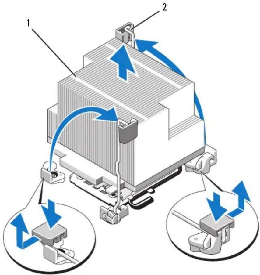
Figure 1-1. Installing and Removing the Heat Sink
1 heat sink 2 release lever (2)
NOTE: Your heat sink may appear differently than the one shown above. See your Hardware Owner's Manual for a system-specific illustration.

CAUTION: The processor is held in its socket under strong pressure. Be aware that the release lever can spring up suddenly if not firmly grasped.
9 Position your thumb firmly over the processor socket-release lever and release the lever from the locked position by pushing down and pulling out from under the tab. Rotate the lever 90 degrees upward until the processor is released from the socket. See Figure 1-2.
10 Use the tab on the processor shield to rotate shield upward and out of the way. See Figure 1-2.
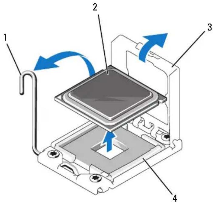
Figure 1-2. Removing a Processor
1 socket-release lever 2 processor
3 processor shield 4 ZIF socket

CAUTION: Be careful not to bend any of the pins on the ZIF socket when removing the processor. Bending the pins can permanently damage the system board.
11 Carefully, lift the processor out of the socket and leave the release lever up so that the socket is ready for the new processor.
After removing the processor, place it in an antistatic container for reuse, return, or temporary storage. Do not touch the bottom of the processor. Touch only the side edges of the processor.
If you are permanently removing the processor, you must install a processor blank and a heat-sink blank in the CPU2 socket to ensure proper system cooling. Adding the blank is similar to installing a processor. See "Installing a Processor".
Installing a Processor

WARNING: Only trained service technicians are authorized to remove the system cover and access any of the components inside the system. Before you begin this procedure, review the safety instructions that came with the system.

NOTE: In a single-processor configuration, the CPU1 socket must be used.
1 If you are adding a second processor for the first time, remove the heatsink blank and the processor blank from the vacant processor socket. Removing the blank is similar to removing a processor. See "Removing a Processor".
2 Remove the processor from the packing material by the processor's edges only. Do not touch the bottom of the processor. Handle the processor carefully with your fingers on the side edges. Place your hand beneath the processor when you are moving it to the system.
3 Locate the pin 1 indicator on the system board socket.
4 Locate the pin 1 indicator on the top of the processor. The pin 1 indicator is shown as a triangle on the top of the processor. See Figure 1-4.

CAUTION: Positioning the processor incorrectly can permanently damage the system board or the processor. Be careful not to bend the pins in the socket.
5 Place the processor over the socket with each pin 1 aligned and level. See Figure 1-3 and Figure 1-4.

CAUTION: Do not use force to seat the processor. When the processor is positioned correctly, it engages easily into the socket.
6 Align the notches in the processor with the socket keys on the ZIF socket. See Figure 1-4.
7 Install the processor in the socket. Keep the processor level (see Figure 1-3) and insert it straight down into the socket. Allow the processor to float on the pins, allowing the processor shield to hold it in place.
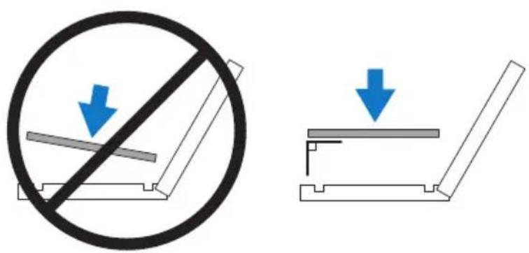
Figure 1-3. Keeping the Processor Parallel to the Socket
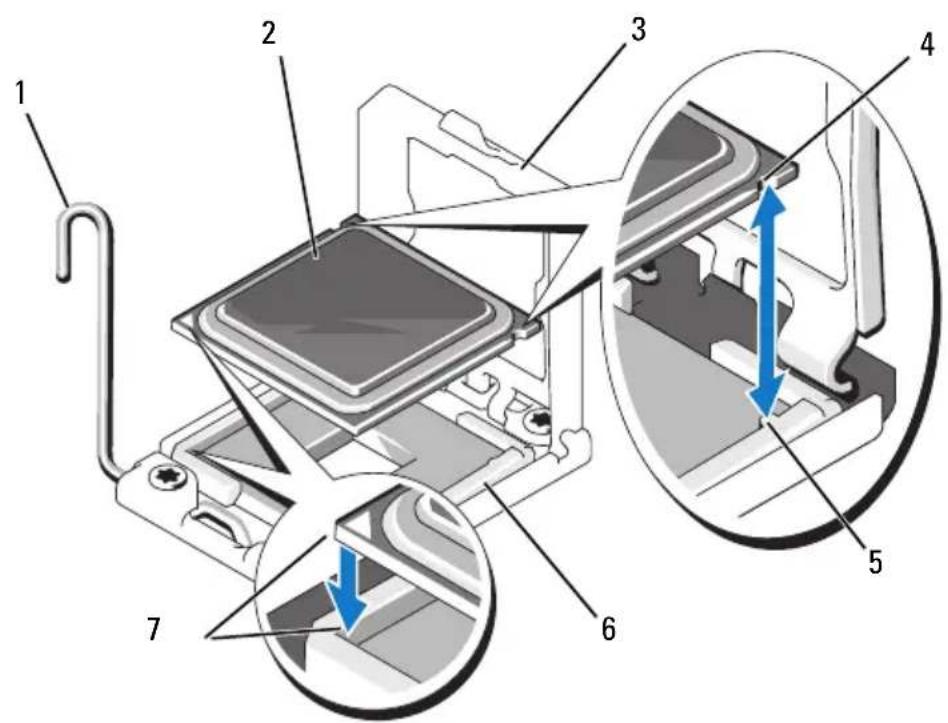
Figure 1-4. Aligning the Processor with the Socket Keys
1 socket-release lever 2 processor
3 processor shield 4 notch in processor (2)
5 socket key (2) 6 ZIF socket
7 pin 1 indicators (2)
8 Verify that the processor is properly aligned and seated.
9 Close the processor shield. See Figure 1-5.
10 Rotate the socket-release lever down until it snaps into place. See Figure 1-5.
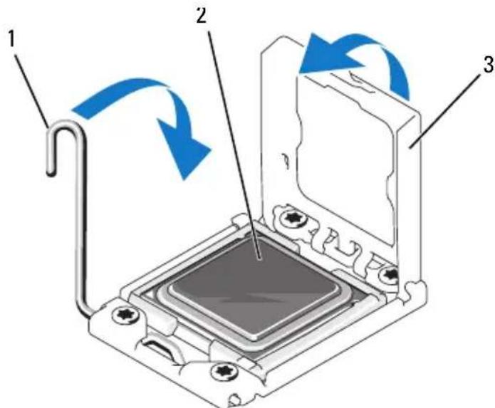
Figure 1-5. Installing a Processor
1 socket-release lever 2 processor
3 processor shield
11 Install the heat sink.

NOTE: Your kit may contain a replacement heat sink if you are installing a processor that consumes additional power. The new heat sink may not appear different than the original one; however, it has improved thermal dissipation specifications and must be used.
a Using a clean lint-free cloth, remove the thermal grease from the heat sink.

CAUTION: Applying too much thermal grease can result in excess grease coming in contact with and contaminating the processor socket.
b Open the grease applicator included with your processor kit and apply all of the thermal grease in the applicator to the center of the topside of the new processor.
c Place the heat sink on the processor. See Figure 1-1.
d Close the heat-sink release levers or replace the screws at the corners of the heat sink. See your Hardware Owner's Manual for a system-specific illustration. See Figure 1-1.
12 Replace the cooling shroud. See "Installing the Cooling Shroud" in the Hardware Owner's Manual.
13 Close the system. See "Closing the System" in the IHardware Owner's Manual.
14 Reconnect your system and peripherals to their electrical outlets, and turn on the system.
15 Press <F2> to enter the System Setup program, and check that the processor information matches the new system configuration. See "Entering the System Setup Program" in the Hardware Owner's Manual.
16 Run the system diagnostics to verify that the new processor operates correctly.
17 See "Running the System Diagnostics" in the Hardware Owner's Manual for information about running the diagnostics.
信息更新
处理器安装
注、小心和警告
*FJ:FJFJFJFJFJFJFJFJFJFJFJFJFJFJFJFJFJFJFJFJFJFJFJFJFJFJFJFJFJFJFJFJFJFJFJFJFJFJFJFJFJFJFJFJ