
ICMPDA4T03 - Flat screen mount Chief - Free user manual and instructions
Find the device manual for free ICMPDA4T03 Chief in PDF.
| Brand | Chief |
| Model | ICMPDA4T03 |
| Product Type | Swiveling Wall Mount for Flat Screen |
| VESA Compatibility | 100x100, 200x100, 200x200, 300x300, 400x200, 400x400 mm |
| Maximum Weight Capacity | 34 kg (75 lb) |
| Material | Steel |
| Color | Black |
| Approximate Arm Dimensions (WxHxD) | 400 x 400 x 150 mm (estimate) |
| Mount Weight | Approximately 4 kg |
| Tilt | Yes, adjustable via tension screws |
| Swivel | Yes, with tension adjustment |
| Extension | Yes, articulated arm |
| Cable Management | Integrated cable covers (parts D) |
| Included Parts | Base plate (B), swivel arm (A), vertical brackets (E), spacers (CC), various screws, hex keys (K, L), cable covers (D) |
| Safety | Do not exceed 34 kg; use provided screws; avoid finger pinching when closing the arm |
| Maintenance | Wipe with a soft, dry cloth |
| Repairability | Standard parts; contact manufacturer for spare parts |
| General Information | 116-page manual available in multiple languages |
Frequently Asked Questions - ICMPDA4T03 Chief
User questions about ICMPDA4T03 Chief
0 question about this device. Answer the ones you know or ask your own.
Ask a new question about this device
Download the instructions for your Flat screen mount in PDF format for free! Find your manual ICMPDA4T03 - Chief and take your electronic device back in hand. On this page are published all the documents necessary for the use of your device. ICMPDA4T03 by Chief.
USER MANUAL ICMPDA4T03 Chief
Milestone AV Technologies, and its affiliated corporations and subsidiaries (collectively, "Milestone"), intend to make this manual accurate and complete. However, Milestone makes no claim that the information contained herein covers all details, conditions or variations, nor does it provide for every possible contingency in connection with the installation or use of this product. The information contained in this document is subject to change without notice or obligation of any kind. Milestone makes no representation of warranty, expressed or implied, regarding the information contained herein. Milestone assumes no responsibility for accuracy, completeness or sufficiency of the information contained in this document.
Chief® and Centris™ are trademarks of Milestone AV Technologies. All rights reserved.

IMPORTANT WARNINGS AND CAUTIONS!

WARNING: A WARNING alerts you to the possibility of serious injury or death if you do not follow the instructions.

CAUTION: A CAUTION alerts you to the possibility of damage or destruction of equipment if you do not follow the corresponding instructions.

WARNING: Failure to read, thoroughly understand, and follow all instructions can result in serious personal injury, damage to equipment, or voiding of factory warranty! It is the installer's responsibility to make sure all components are properly assembled and installed using the instructions provided.

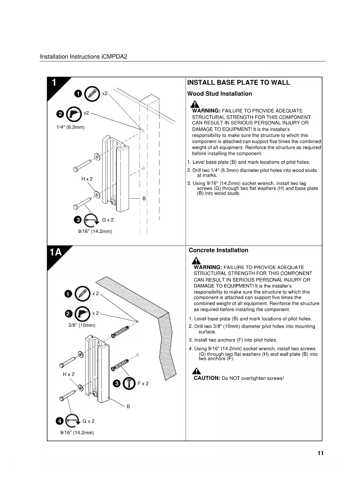
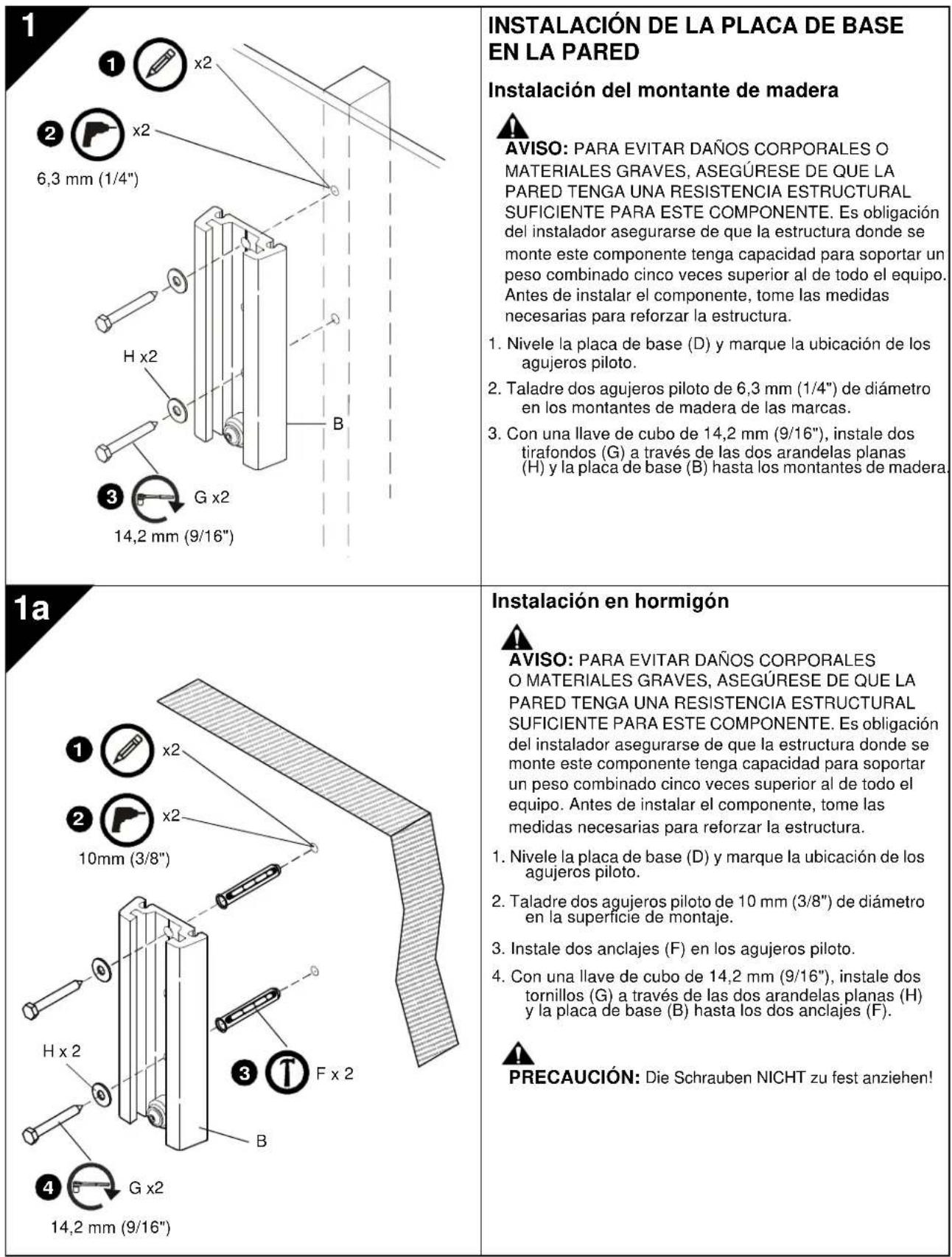
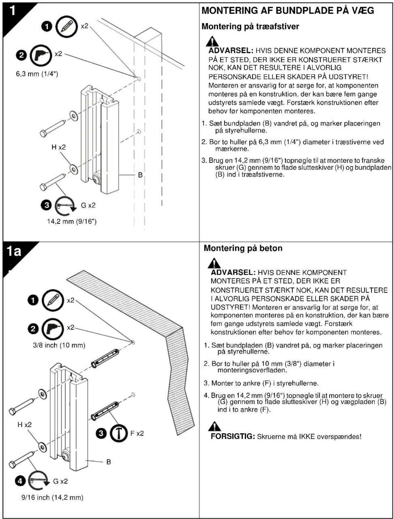
WARNING: Failure to provide adequate structural strength for this component can result in serious personal injury or damage to equipment! It is the installer's responsibility to make sure the structure to which this component is attached can support five times the combined weight of all equipment. Reinforce the structure as required before installing the component.

WARNING: Exceeding the weight capacity can result in serious personal injury or damage to equipment! It is the installer's responsibility to make sure the combined weight of all components attached to the iCMPDA2 does not exceed 75 lbs (34kg).

AVISOS Y PRECAUCIONES IMPORANTES!

Installation Instructions

PNEOCTEPEKHEIPEIOCTEPEKHEIPEPOBDITABOTOBHOCTBACXBOMOXHOCTNNOPEJDEHNNnpa3pyeHNObpyoBAHHcnnBuHe cneyete 3aOOHTCTAYQUAMMHNHCPTyRDAH.

PNDYPKDEHNEOTK3AHTATB,TIO6BJNOHOCTbO NOHTb,N CIEp083b3a BOEMV HCTPYKMMMOKET pNBECTcKOBpEHHOMY TEECHMOY NPOPEKDEHNO NOPEKDEHNE OOBOPDyABHIN,IMN OOB6kDEHNO 4oBPHNORAPAHNTI 1TO-OTBCTBENHOCTMONTAXHNO yDOCTEPBHTC,YTO BOKOMONHEHITJDRGNHMOBpOAMO CO6PAHn yCTAHABRMIA MNCNtBQAHNE pNDQCTAEHNHIXHINTCPKNI.

PNDQPYEKEHNE. OX3a 06eBcHnAaTb AekBaHNY CtpkTyPOAHTI 3TOKOMNHOHEA MOKET PnBcCTIK CepbEhMOY TeneCHOMY NOBpEeHNOHINIO NOBpEeHITb Hb OOpyoBBHNE! 3TO -OTBCTBENHOCTM OMHTAHXNKAA YQDOCTeBPRTCA KCTCPKya, K KOTOPR PNAXONHKH 3OT KOHOMNH, MOKET NODpeKXBt BnPTb PA3 o6bEHNHHB BE ACERoO6OpOBAHn. YKPenTeC TcPtyOy KaK TpeSyTEr pEPd MOKTAKOMKOMHOHNTA

IMPORTANT! If the display has a 100 × 100mm recessed mounting hole pattern, then display must be mounted to swing arm (A) before swing arm is installed to base plate (B). See "INSTALL DISPLAY, 100 × 100mm Recessed Mounting Hole Pattern". Continue below after display is installed.

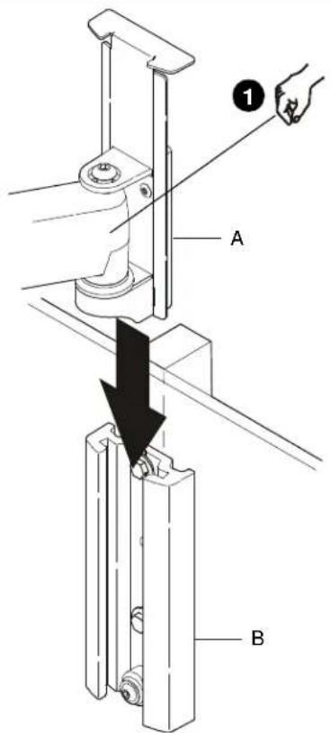
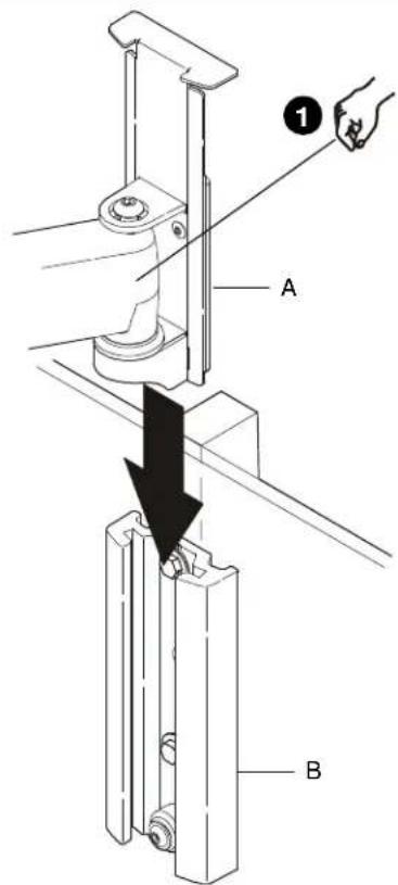
CAUTION: PERSONAL INJURY MAY OCCUR IF SWING ARM COLLAPSES AGAINST FINGERS! Be alert, keeping hands and fingers out of pinch points during installation.
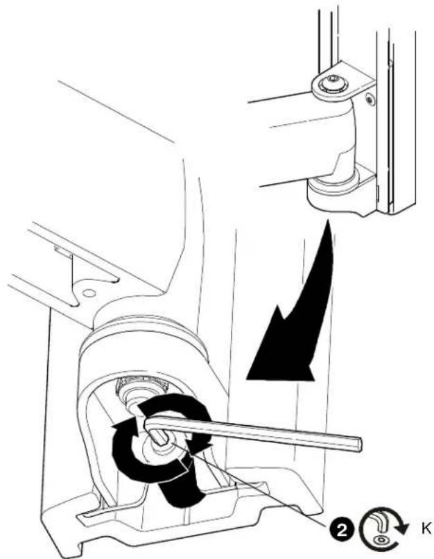
- Slide swing arm mounting bracket (A) down into base plate (B).
- Secure swing arm (A) to base plate (B) by tightening screw with hex key (K).
3
INSTALL DISPLAY
IMPORTANT! Proceed as directed below:
If installing a display with a 200x100, 200x200, 300x300, 400x200, or 400x400mm mounting hole pattern, proceed to Step 3A.
If installing a display with a 100× 100mm mounting hole pattern, proceed to step 3B or 3C, as applicable.
3A
200x100, 200x200, 300x300, 400x200 or 400x400 Mounting Hole Pattern
Attaching Vertical Brackets

WARNING: IMPROPER INSTALLATION CAN LEAD TO MOUNT FALLING CAUSING SERIOUS PERSONAL INJURY OR DAMAGE TO EQUIPMENT! DO NOT substitute hardware. Only use hardware provided or specified by manufacturer.
- Determine and mark the vertical center position between the left side upper and lower mounting holes in display.
- Determine and mark the vertical center position between the right side upper and lower mounting holes in display.
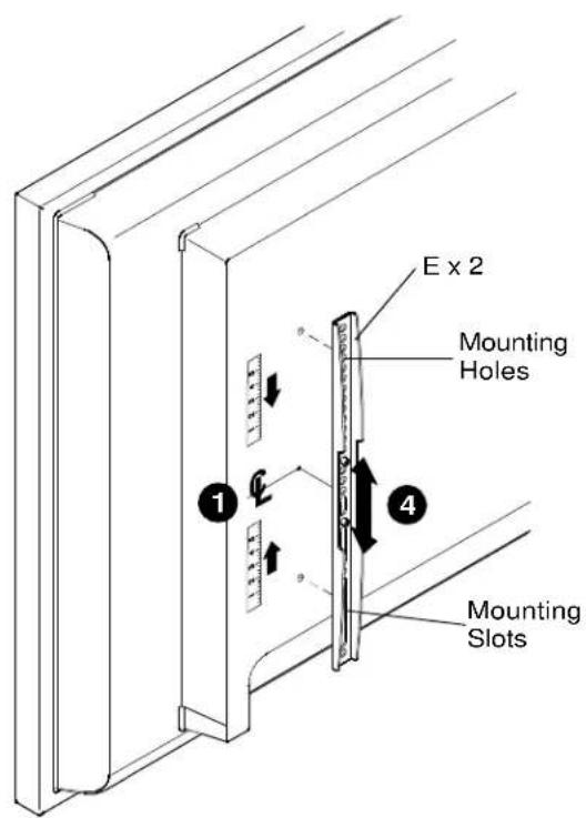
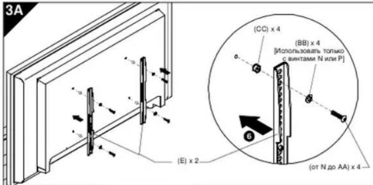
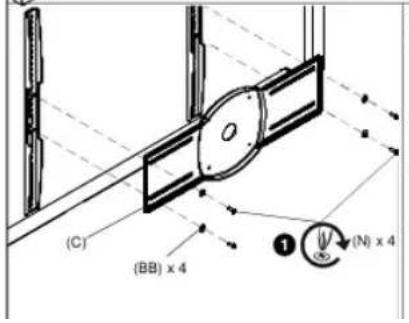
- Orient vertical mounting bracket (E) so that mounting holes are on top and mounting slots are on bottom.
- Align mounting holes and slots in vertical mounting bracket (E) with upper and lower mounting holes in display.
- Adjust vertical mounting bracket (E) position until mark made in Step 1 aligns with center mark in vertical mounting bracket (E).
- Secure left side vertical mounting bracket (E) to display using two Phillips pan head screws (N through AA).
NOTE: Also use #10 flat washers (BB) if using screws N or P.
NOTE: If the display has a recessed mounting surface, protrusions or a power box, a spacer and longer mounting hardware must be placed between the display and vertical mounting brackets (E).
7. Repeat Steps 3 through 6 for right side vertical mounting bracket using the same hole locations to align brackets horizontally.

3B
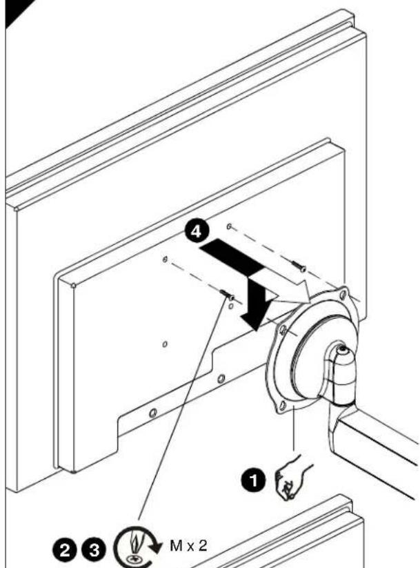
100 x 100mm Flush Mounting Hole Pattern
IMPORTANT! This procedure only applicable when 100 × 100 mm mounting holes on back of display are flush with back surface of display, OR brackets (C, E) were previously installed per Step 3A.

WARNING: EXCEEDING THE WEIGHT CAPACITY CAN
RESULT IN SERIOUS PERSONAL INJURY OR DAMAGE TO EQUIPMENT! It is the installer's responsibility to make sure the combined weight of all components attached to the iCMPDA2 does not exceed 75 lbs (34 kg).
- Ensure Centris bracket can swivel and tilt easily, yet still be tight enough to hold display in desired position. Adjust as required before proceeding. See "ADJUSTMENT".

UPTION:USING SCREWS OF IMPROPER SIZE CAN
DAMAGE DISPLAY! Screws should easily and completely thread into display mounting holes.
-
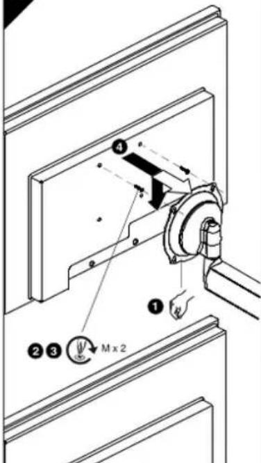
Using a Phillips screwdriver, install two screws (M) into upper threaded mounting holes in back of display (or in brackets C, E; if installed).
-
Thread screws completely into display (or in brackets C, E; if installed), then back out 3 complete turns.

WARNING: INADEQUATE THREAD ENGAGEMENT IN DISPLAY CAN LEAD TO MOUNT FALLING CAUSING SERIOUS PERSONAL INJURY OR DAMAGE TO EQUIPMENT! Back out screws ONLY as necessary to allow installation of Centris bracket!
- Lift and align display so that screws in back of display (or in brackets C, E; if installed) fit into upper teardrop mounting holes in Centris bracket. Lower display into place.
NOTE: DO NOT tighten screws at this time.
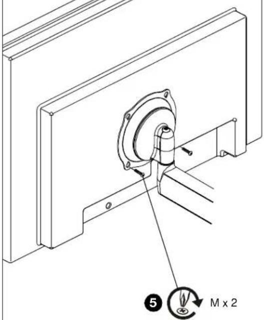
- Using Phillips screwdriver, install two screws (M) through lower teardrop mounting holes in Centris bracket into display (or in brackets C, E; if installed).
- Tighten all four screws (M). Do not overtighten!
3C
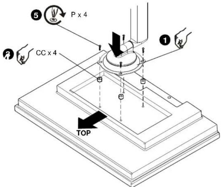
100 x 100mm Recessed Mounting Hole Pattern
IMPORTANT! This procedure only applicable when 100 × 100 mm mounting holes on back of display are recessed into back surface of display.

WARNING: EXCEEDING THE WEIGHT CAPACITY CAN RESULT IN SERIOUS PERSONAL INJURY OR DAMAGE TO EQUIPMENT! It is the installer's responsibility to make sure the combined weight of all components attached to the iCMPDA2 does not exceed 75 lbs (34 kg).
- Ensure Centris bracket can swivel and tilt easily, yet still be tight enough to hold display in desired position. Adjust as required before proceeding. See "ADJUSTMENT."
- Carefully place display face down on protective surface.

CAUTION: USING SCREWS OF IMPROPER SIZE CAN DAMAGE DISPLAY! Screws should easily and completely thread into display mounting holes.
- Place four spacers (CC) over mounting holes in display back.
- Orient mount so that teardrop mounting holes in Centris bracket are aligned with holes in four spacers (CC).

WARNING: INADEQUATE THREAD ENGAGEMENT IN DISPLAY CAN LEAD TO MOUNT FALLING CAUSING SERIOUS PERSONAL INJURY OR DAMAGE TO EQUIPMENT!
- Using a Phillips screwdriver, install four screws (P) through four teardrop mounting holes in Centris bracket and spacers (CC) into display. Tighten all four screws (P). Do not overtighten!
- Continue with "INSTALL SWING ARM TO BASE PLATE".
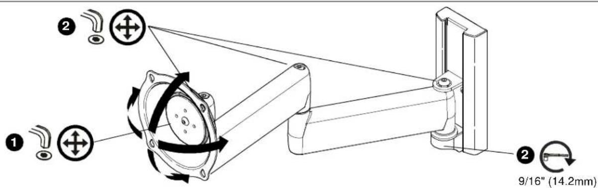
4 ADJUSTMENT
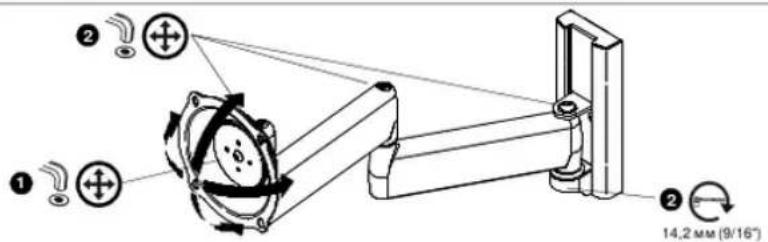
- To adjust pitch tension, slightly loosen or tighten adjustment screw as required using hex key (K).
NOTE: If display is mounted to swing arm (A) then first disconnect all cables and remove display (Refer to "INSTALL DISPLAY").
- To adjust extension and swivel tension, slightly loosen or tighten adjustment screws as required using hex keys (K, L).
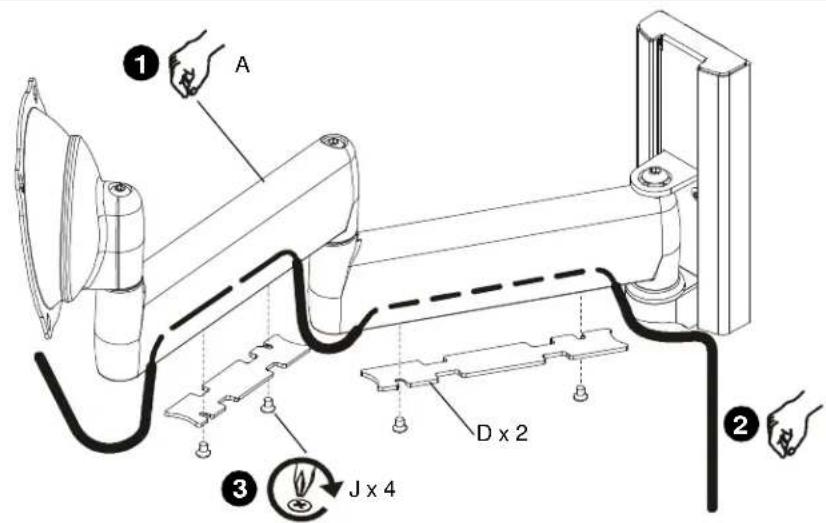
5 CABLE MANAGEMENT

CAUTION: Ensure that adequate cable slack exists for movement of display, and that cables will not be pinched by installation of covers (D) or screws (J).
- Move swing arm (A) to fully extended position.
- Carefully position cables in cavity located in lower portion of each arm.
- Using Phillips screwdriver, install covers (D) using screws (J).
2
INSTALACION DEL BRAZO MOVIL EN LA PLACA DE BASE
WAARSCHUWING! ONEIGENLIJEK
INSTALLATIE KAN LEIDEN TOT VALLEN VAN
MONTAGEONDERDELEN, DIT KAN
RESULTEREN IN ERNSTIGE VERWONDINGEN
DYNPEXDEHME. HEPABINbHAR
YCTAHOKA MOKOT INP BYBECTN KPADEHIO YCTPOCTBAI Bb3BATc CEPbE3HbE TPABMJI NEPCOHAIA INOBPEKHEIA OBOPYDOBAHARI 3ANPEPAJETCR HONOBOTAR NepoepnHAnk npexenCneyertncn08tBor ToTko npexen, npceoCTAENHHnnn nnpapesehenn KnpmpeHnno npom3aQkTeHN.
- HauDHTe IOTMTBeTe CEENTpaHHe NOONOKEHNE NO BcTbVKAIA MKNY DBeBMA BcXHMM HKHOOMM BOHTMQHOAM OTBCECTVRN MOHOTOPA.
2.Haikinte NOTMTBeTae UENTPAHoe NOONKHEWNE NO BEPTKAMMSEyPbSBAI BEPXHHMM HIXHXMM MOHTAKBHMM OTBCTPMMAH MOHOTOPA.
3.YCTAHONTEKPOHJTHBEPHTAALHOX KEPENHNAE(E)TAOKOMOAP3CM,TOOSMOHTAKHMAB OTBOPETNRAHXADINCBABEXPY.AMOHTAKHMAB CNTSH-BHH2X. - COBmECTHcTe MCHAKHeOT BEPCTHn CNTOa H E KEBMCHNOM XPOCHITEeE (E) C E BPHAMN H IHOKHAMMOHTXAOHBOTBETRMMOHOTOPA
- Pemyipnye tata nolexenchen beetvkrnshoro KOKHUTHEA (E) DO COOMENCHENBEETVKRNSHAOI
MONTAK cHTpNbHoro KPOHTeHa
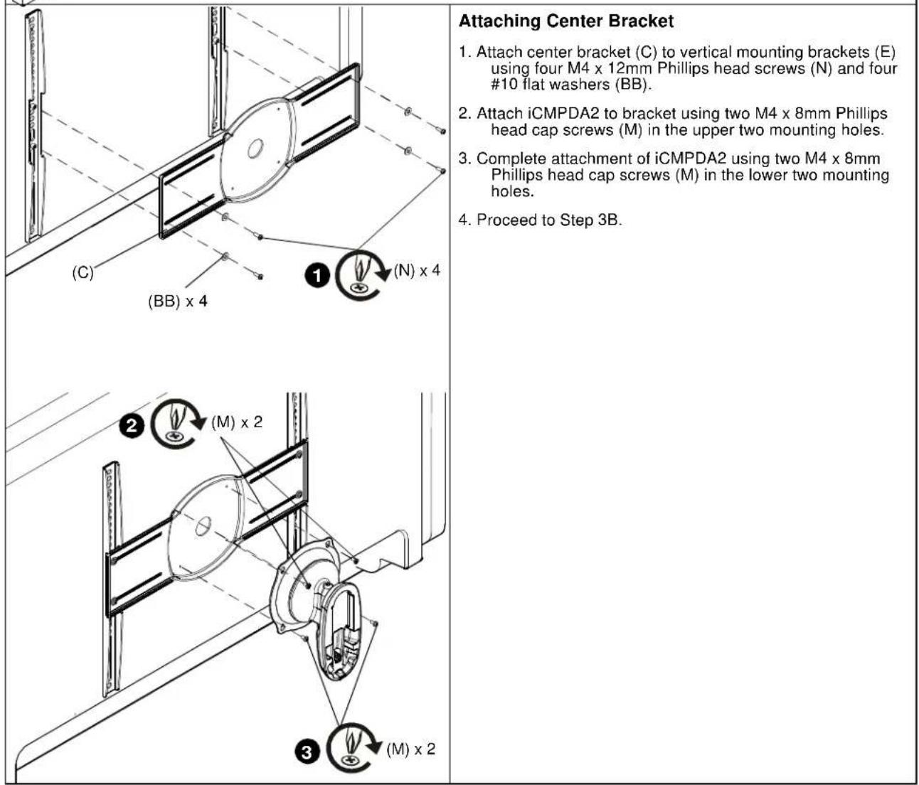
- Pnmpneite nentpahnbnk hpoonrHc (C) K BETKANHm KPOOHHTeHAM (E) npa NOMO YetbEXe BnHOu Philips c roNkoM4 Mx 12 MM (N) NtHAPTE NOONXs 56 No 10 (BB).
- ⅡPENPENIECMPDA2KPOHHTAHTAEPYTAaBAAHTA Phillips c roLoXoM4 X8MM (M) aBepxHnMoTAXHXe OBAEPTX.
- 3aBepuTeMOTaxICMPDA2.3xKpyTbAaBHHTa Phillips c nooaxoM A4 x8 MM (M) aHxHOe MOHTaxOHe OTABCTy.
- Ipepeepre Xuary 3B
3B
Ua6bONKpeneKbIXbOTBcETHn 100x100 MM, OTEbPcNpaTOnOKeHN3aNoDnIoo
BAKHO! 3ra npoueUpya npmMnMa tonbko ecnn xpeNEXhae otBpCTMa HA aadn cTneE dnncn paoonoxnxno noa5owny 100x100 MM 3anodnupc c3adne nopaeXkOchTxo dnnner, INIIN paabe HbB yctAtoAnoeHc XcbO (C,E) cornacho wamar 3A.

PENPYNPNKDEHNE: PEBBIIIEHNE DONYCTVMOJ
BECOBON HAPY3KMOKET NOBIEb CEPbE3HbIE TPABMbIHNPOBPEKDEHEO BOPDYOBAHRII HIOO.OCyueCTANKouee yctahoxy,063aHO pncpeDAta 3e TM. Tc0bU cympaHaeMaCCa Boex KOMOHTeTO, yctahNOHHNHex HAICMPDA2, nepebsuana 34 kT (75kytoR).
- 06paHtne bHmHnHe: oKo3aCentrIs pOkoHnREKO
nooPbOHbTaBcN HAKNOHBTBo, HO npo TAmO pOBOKa BbH
3AHTHYa DOCTAOHO DTOI TORO, TTObU dyEeXOBaBbDIOHNE
BHXOHOM NOONEXHb, PIXpeXHE NEM peKoDyM
KdALBeHHMM DECTBHMR, HnEOKoDPMOOCTH
OTpyENYPOBAt, CM.-PEYINIPOBKA.

PNEDOCTEPEXEHNE:PNINCNIOB3OBAHNI
BHTOB HENIOJXIOJUERO PA3MEPA BO3MOXHO NOPEBXDEHNE DACNPIER BHTbDdoJNOHnI HENO
- Kectoofoa3nohtoeepno3aaephytaaiaHTa(M) eaepeHne pte608e xpeeneknue oraeprrna HA 3aehn cheke dncnner (knu a ckoabCxG; E: ecnyctananeH).
3 enoNtctbAaeeBpynHbAaIaBnnn (nna a cbo6bC E, ecn ycaTbaonBnHb)atem oTaebpyhBa n noThbnbOobpa

PNEYNTPEKDEHHE:HEIOCTATOHOE 3ABHHAHHEBHTOBINKPENIEHMAACNPIER MOKETIPVBECTNIKAIDEHMOKPNIEHARIIOBNEbCEPE3HbTEPABMBINIOBPEKDEHHE OBOPYDBOAHIRTOAOAHOHHOHTOIOTKOHOHNO
3C
W650H KpEeKbIx OTBepTm 100 x 100 MM C 3aRny6nHem
BAXHOI 37a npouzya pnpimnEe TONTOO eCNI KPNEXKHe OteAepCTH, paonionkHeHne no 100 x 100 MM. 2aaybEyHb a 3a4ho n oaeXPoctb cIacn.

PNEYDPEKDEHNE: PNEBbIeHEMEOITGYCTYMOM BECOBMOHAPy3MOKETNOBIEbCEpE3HbIE TPABMbIINIOBPEKDEHME OOBPOYOBAHNRIuOcuyctarAOe ycaHOxky.683aNopeoehnTb 3TeM,HTo6bI cymaapnaMaCCaBCX komoHeHToA,yctHOaNeHHHX HAICMPDA2.He pEBuaaTa 34KT (75fnoTHo)
- 06pHHTe HMMHmKcO6aCentrIsOnnHspeKoNobopMaBtCnHAKNOHRTCB,HO npA tOMdoKoHb6bT B3HpytaDcatoTHoIraToro,TOyBu yzePbMAtnBnEaBHyKoNIOKeHHN.PpeKzHMepeKoHpaTb KdahnHeuMmDeTbAim,npNeHo6OAMoCTnOpTeYnpoBaTb.CM-PEYTNPOBKA.
2.Axypathno nonoxkntb dncnneR nueebo CTPOHOH BHN H BAUNTHYIO NOBepXHOCTb.

PNEOCTEPEXHEME:IPNINIOB3OBAHIMBVHTOB HENOPOXIUEROPA3MEPA BO3MOXHOIOBPEXHEME DNCIIIE! BnHbdoKbneNOHNOCbBOAAMHBATCBxKPENEXHBE OTEPCBnDnON.
- Pnoknty hte tyepe dctanpnohne styn (CC) na kpenexohne otepctna 3aedher ctenke daenner.
PaoonnoxKpnnepe Ta, T0bI KanneBnBe XpeNekHbAtepCnA CxOe BcmeTINbc C oTaePCNnMnB Hertbpex DactaONHbBtynkX (CC).

PNEYPTPEKDEHNE:HEOCTATOHHOE3ABHHNBAHNE BVHTOB PIPKNPEJIENM DNCIEMOXETIPIVBECTKNADEHNO KEPENIEHNRIOBIEy CEPbE3HbIE TPABMbI NIMTOBPEXDEHNEOBOPYDBOAHAR
- Kpeo06ba3n0y 3aBepHy7e BnVt (P) hepe7e3pKanEbnkx npenckoxhOy 0BepTBA 8c06eCentrix vBnyn (CC) aKn13, 3A9y7b0e Boe pBe nBn (P). He nepetbnmbat?
- NpeepnKpaednyKPENIEHNEIOBOPOTHO KPOHHTEHA KIIACTVHE OCHOBAHNA

4
PEYNIPOBKA
I JINHAYPIMNCHNPHKCAKNAIPN HAKNOHE cnerka ccnbahtbnn 3a3THTy perynpoBBHH BHNH NHOHc wneurpanen no npok (K).
PIMEMAHHE: Ecme pncnnepehnn KnoepoTHm npohmtey (A), Chana otocepeHbBo kabe m nchrt pncn (Cm. YCTAHOBKA DCNTNER.).
2.Длрургбхснчсдсрпгдзнлгдзнлгдзнлгдзнлгдзнлгдзнлгдзнлгдзнлгдзнлгдзнлгдзнлгдзнлгдзнлгдзнлгдзнлгдзнлгдзнлгдзнлгдзнлгдзнлгдзнlгдзнlrgd3n
5
POKIADKA KABENEI

PNEOCTEPEKHEH: Pnocpnd3a Tm, YIO6i KaBne IINMENI pOBVANHc, DcOATAOHcDPRNepemaenrA dnCnne, He n 3aoKnnncnnpraYtOahONBe KxHKe (D) HnBHToB (J).
- YCTAHOBHTb KPOOHTEH (A) a nonHOCTBO bHTIRHYTOE NOXEHNE.
- AxypatthopnoipnolaohtbKa65Ba n noocctk,pactonokkeHHux C Hxohc hctopohai 06bx xactre kponohtteHa.
- 3aepenntb Kpbkun (D) bHTAMn (J) c nmooubo kpeo06pa3HO OTBepTK
2
MONTERING AF SVINGARM PÅ BUNDPLADE
USA·8401 Eagle Creek Parkway, Suite 700·Savage, Minnesota 55378·800.572.1373
EMEA·+31(0)402668620
www.icmounts.com
©2009 Milestone AV Technologies. The iC Logo and StowAway are trademarks of Chief Manufacturing,
a products division of Milestone AV Technologies, a Duchossois Group Company. All rights reserved
Patents and patents pending. Milestone AV Technologies, Savage, MN 55378, USA
8800-002045 Rev 00
11/09
- IMPORTANT WARNINGS AND CAUTIONS!
- AVISOS Y PRECAUCIONES IMPORANTES!
- Installation Instructions
- 3
- INSTALL DISPLAY
- 3A
- 200x100, 200x200, 300x300, 400x200 or 400x400 Mounting Hole Pattern
- Attaching Vertical Brackets
- 3B
- x 100mm Flush Mounting Hole Pattern
- 3C
- x 100mm Recessed Mounting Hole Pattern
- ADJUSTMENT
- CABLE MANAGEMENT
- INSTALACION DEL BRAZO MOVIL EN LA PLACA DE BASE
- MONTAK cHTpNbHoro KPOHTeHa
- Ua6bONKpeneKbIXbOTBcETHn 100x100 MM, OTEbPcNpaTOnOKeHN3aNoDnIoo
- W650H KpEeKbIx OTBepTm 100 x 100 MM C 3aRny6nHem
- 4
- PEYNIPOBKA
- 5
- POKIADKA KABENEI
- MONTERING AF SVINGARM PÅ BUNDPLADE
Brand : Chief
Model : ICMPDA4T03
Category : Flat screen mount