iCLPFM2T03 - Flat screen mount Chief - Free user manual and instructions
Find the device manual for free iCLPFM2T03 Chief in PDF.

| Product type | Wall mount for flat panel display |
| Brand | Chief |
| Model | iCLPFM2T03 |
| Maximum load capacity | 90.7 kg (200 lb) |
| Material | Steel |
| Color | Black (typical) |
| Screen compatibility | Flat panel displays with VESA standard (M4, M5, M6, M8 screws depending on kit provided) |
| Rail dimensions (approx.) | Length: approx. 600 mm, adjustable in width |
| Tilt | No (static model) |
| Wall attachment | On wood stud or concrete wall |
| Minimum distance between wall brackets | 304.8 mm (12 in) |
| Maximum drywall thickness | 16 mm |
| Tools required for installation | Drill, 5.5 mm drill bit (wood) or 10 mm (concrete), level, wrench |
| Supplied hardware | Lag bolts, washers, concrete anchors |
| Safety | The structure must support 5 times the total weight; do not exceed capacity |
| Maintenance | Wipe with a soft cloth; periodically check the tightness of hardware |
| Spare parts | Contact Chief customer service for replacement parts |
| Repairability | Product repairable by a professional installer |
| Warranty | Refer to the manual for warranty terms |
| Country of manufacture | Not specified in the manual |
Frequently Asked Questions - iCLPFM2T03 Chief
User questions about iCLPFM2T03 Chief
0 question about this device. Answer the ones you know or ask your own.
Ask a new question about this device
Download the instructions for your Flat screen mount in PDF format for free! Find your manual iCLPFM2T03 - Chief and take your electronic device back in hand. On this page are published all the documents necessary for the use of your device. iCLPFM2T03 by Chief.
USER MANUAL iCLPFM2T03 Chief
natural_image
Technical line drawing of a mechanical assembly with two vertical rods and a central rod, labeled 'ICLPFM2' (no other text or symbols)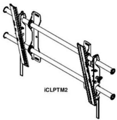
natural_image
Technical line drawing of a mechanical assembly with two parallel rods and a central rod, labeled 'iCLPTM2' (no other text or symbols)DISCLAIMER
Milestone AV Technologies, and its affiliated corporations and subsidiaries (collectively, "Milestone"), intend to make this manual accurate and complete. However, Milestone makes no claim that the information contained herein covers all details, conditions or variations, nor does it provide for every possible contingency in connection with the installation or use of this product. The information contained in this document is subject to change without notice or obligation of any kind. Milestone makes no representation of warranty, expressed or implied, regarding the information contained herein. Milestone assumes no responsibility for accuracy, completeness or sufficiency of the information contained in this document.
Chief® is a registered trademark of Milestone AV Technologies. All rights reserved.
IMPORTANT WARNINGS AND CAUTIONS!
WARNING: A WARNING alerts you to the possibility of serious injury or death if you do not follow the instructions.

CAUTION: A CAUTION alerts you to the possibility of damage or destruction of equipment if you do not follow the corresponding instructions.

WARNING: Failure to read, thoroughly understand, and follow all instructions can result in serious personal injury, damage to equipment, or voiding of factory warranty! It is the installer's responsibility to make sure all components are properly assembled and installed using the instructions provided.

WARNING: Failure to provide adequate structural strength for this component can result in serious personal injury or damage to equipment! It is the installer's responsibility to make sure the structure to which this component is attached can support five times the combined weight of all equipment. Reinforce the structure as required before installing the component. The wall to which the mount is being attached may have a maximum drywall thickness of 5/8" (1.6cm).

WARNING: Exceeding the weight capacity can result in serious personal injury or damage to equipment! It is the installer's responsibility to make sure the combined weight of all components attached to the iCLPFM2/iCLPTM2 does not exceed 200 lbs (90.7 kg).
![[49.8] 1.96 31.8" (807.7 mm) WITHOUT SWITCHING UPRIGHTS 34.5" (876.3 mm) WITH SWITCHING UPRIGHTS [304.8] 12.00 MINIMUM WALL SPACING [55.3] 2.18 [152.4] 6.00 C/L OF MOUNT [304.8] 12.00 [36.6] 1.44 [25.4] 1.00 [8.6] .34 [38.5] 1.52 [533.4] 21.00 RAILS CAN BE SLID LEFT OR RIGHT FOR OFFSET [878.8] 34.60](/content/2026/02/354721/images/8abcb6680d00e614bfafdb4a655671dc6556c9492a93f838ad5ccdc8a4b8f228.jpg)
bar
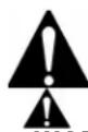
| Label | Value | |---|---| | [13.5] | 0 | | [29.2] .53 | 1.15 | | [41.7] | 1.64 | | [66.7] 2.13 | 2.13 | | [79.2] | 3.12 | | [91.7] 3.61 | 3.61 | | [104.2] 4.10 | 4.10 | | [116.7] 4.59 | 4.59 | | [129.2] 5.09 | 5.09 | | [141.7] 5.58 | 5.58 | | [154.2] 6.07 | 6.07 | | [166.7] 6.56 | 6.56 | | [179.2] 7.06 | 7.06 | | [191.7] 7.55 | 7.55 | | [204.2] 8.04 | 8.04 | | [216.7] 8.53 | 8.53 | | [229.2] 9.02 | 9.02 | | [241.7] 9.52 | 9.52 | | [254.2] 10.01 | 10.01 | | [266.7] 10.50 | 10.50 | | [279.2] 10.99 | 10.99 | | [366.7] 14.44 | 14.44 | | [379.2] 14.93 | 14.93 | | [466.7] 18.37 | 18.37 | | [479.2] 18.87 | 18.87 | | [519.9] 20.47 | 20.47 |iCLPTM2
![[134.5] 5.29 30.6" (777.2 mm) W/O SWITCHING UPRIGHTS 35.4" (899.2 mm) WITH SWITCHING UPRIGHTS [304.8] 12.00 MINIMUM WALL SPACING [25.4] 1.00 [152.4] 6.00 C/A OF MOUNT [336] 13.23 [36.6] 1.44 [25.4] 21.00 [304.8] 12.00 [55.7] 2.19 [8.6] .34 [878.8] 34.60 [50.8] 2.00 1.98" (50.3 mm) DEEP WHEN FLAT TO WALL 12° MAX TILT](/content/2026/02/354721/images/e451b5e23fb72e1dd2482499aa356c4f634900f8acf8554260fad12cfc648a71.jpg)
![[13.5] [29.2] .53 [41.7] 1.15 [54.2] 1.64 [66.7] 2.13 [79.2] 2.63 [91.7] 3.61 [104.2] 4.10 [116.7] 4.59 [129.2] 5.09 [141.7] 5.58 [154.2] 6.07 [166.7] 6.56 [179.2] 7.06 [191.7] 7.55 [204.2] 8.04 [216.7] 8.53 [229.2] 9.02 [241.7] 9.52 [254.2] 10.01 [266.7] 10.50 [279.2] 10.99 [366.7] 14.44 [379.2] 14.93 [466.7] 8.37 [479.2] 18.87 [519.9] 20.47 21.00](/content/2026/02/354721/images/9324c979d376761549aba90974476be184f8ce6940438a42bc5137aee62d26f7.jpg)
ASSEMBLY AND INSTALLATION
The iCLPFM2 and iCLPTM2 have been designed to be mounted directly onto either a wood stud or concrete wall. The iCLPFM2 has static brackets which keep the TV in an upright position. The iCLPTM2 has brackets which allow the TV to be tilted.

WARNING: IMPROPER INSTALLATION CAN LEAD TO MOUNT FALLING CAUSING SEVERE PERSONAL INJURY OR DAMAGE TO EQUIPMENT! It is the installers responsibility to make certain the structure to which the mount is being attached is capable of supporting five times the weight of the iCLPFM2 or iCLPTM2 and all attached equipment not to exceed 200 lbs (90.7 kg).
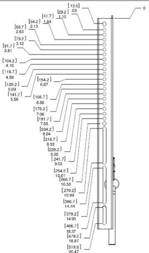
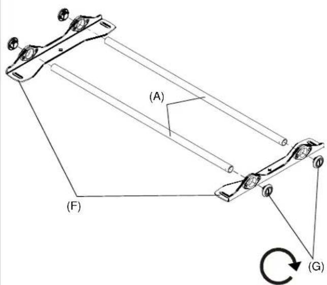
Assembling the Wall Mount
- Place both wall uprights (F) on the floor.
- Slide rails (A) into wall uprights.
- Thread endcaps (G) into the end of each rail.
NOTE: Proceed to either the Installing to a Wood Stud Wall (2a) section or the Installing to a Concrete Wall (2b) section.
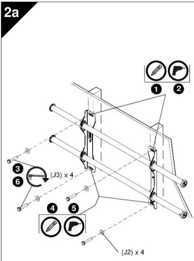
2a
Installing to a Wood Stud Wall
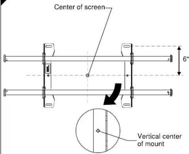
- Determine the center of the TV screen, and where it should be located on the wall.
- Locate the closest stud to the left and right of the selected location.
NOTE: If the screen area lies over a stud, use that stud and the stud to either the left or right of it. - Line up the diamond on mount with center of screen marking to determine vertical center.
- Measure up 6" from the center point to mark location of the upper mounting slots.
- Using a level, mark the wall on each stud to attach the mount through the upper mounting slots.

WARNING: ELECTRICAL SHOCK HAZARD! CUTTING OR DRILLING INTO ELECTRICAL CORDS OR CABLES CAN CAUSE DEATH OR SERIOUS PERSONAL INJURY! ALWAYS make certain area behind mounting surface is free of electrical wires and cables before drilling or installing fasteners.

WARNING: EXPLOSION AND FIRE HAZARD! CUTTING OR DRILLING INTO GAS PLUMBING CAN CAUSE DEATH OR SERIOUS PERSONAL INJURY! ALWAYS make certain area behind mounting surface is free of gas, water, waste, or any other plumbing before cutting, drilling, or installing fasteners.
- Drill one 7/32" (5.5mm) pilot hole in each stud.
- Use two 5/16 x 2-1/2" lag bolts (J3) and two 5/16" flat washers (J2) to attach top of mount to wall.
- Mark the attachment points for the lower mounting slots, making sure the attachment points are located on the studs.
- Drill 7/32" (5.5mm) pilot holes at markings for lower mounting holes.
- Use two 5/16 x 2-1/2" lag bolts (J3) and two 5/16" flat washers (J2) to attach the mount to the wall through the lower mounting holes.
- Slide rails to approximate center of screen location.
2b
Installing to a Concrete Wall
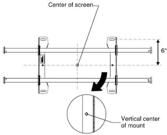
- Determine the center of the TV screen, and where it should be located on the wall.
- Line up the diamonds on mount with center of screen marking to determine vertical center.
- Measure up 6" from the center point to mark location of the upper mounting slots.

CAUTION: MINIMUM HORIZONTAL DISTANCE BETWEEN WALL BRACKETS IS 12". Do not place mounting brackets closer together than 12".

WARNING: ELECTRICAL SHOCK HAZARD! CUTTING OR DRILLING INTO ELECTRICAL CORDS OR CABLES CAN CAUSE DEATH OR SERIOUS PERSONAL INJURY! ALWAYS make certain area behind mounting surface is free of electrical wires and cables before drilling or installing fasteners.

WARNING: EXPLOSION AND FIRE HAZARD! CUTTING OR DRILLING INTO GAS PLUMBING CAN CAUSE DEATH OR SERIOUS PERSONAL INJURY! ALWAYS make certain area behind mounting surface is free of gas, water, waste, or any other plumbing before cutting, drilling, or installing fasteners.
2b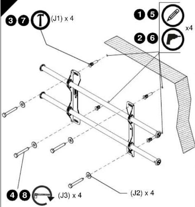 | 1. Using a level, mark the wall through both upper mounting slots.2. Drill one 25/64" (10mm) pilot hole at each marking.3. Install an anchor (J1) into each pilot hole using a hammer.4. Use two 5/16 x 2-1/2" lag bolts (J3) and two 5/16" flat washers (J2) to attach top of mount to anchors in wall.5. Mark the attachment points for the lower mounting slots.6. Drill one 25/64" (10mm) pilot hole at each marking for lower mounting holes.7. Install an anchor (J1) into each pilot hole using a hammer.8. Use two 5/16 x 2-1/2" lag bolts (J3) and two 5/16" flat washers (J2) to attach the mount to the wall through the lower mounting holes.9. Slide rails to approximate center of screen location. |
3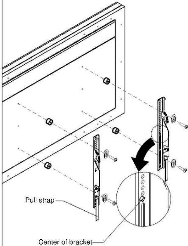 | Attaching Interface Brackets to TV1. Align the center of the bracket with center of screen.NOTE: The diamond-shape hole in the bracket corresponds to the center of the mount.WARNING: IMPROPER INSTALLATION CAN LEAD TO DISPLAY FALLING CAUSING SERIOUS PERSONAL INJURY OR DAMAGE TO EQUIPMENT! Using screws of improper size may damage your display. Properly sized screws will easily and completely thread into display mounting holes. If spacers are required, be sure to use longer screws of the same diameter.2. Select correct screws, spacers (if necessary) and universal washers from the hardware bag (H) and attach brackets to back of screen. |
4

natural_image
Abstract black curved arrow symbol with a circled number 2, no text or labels present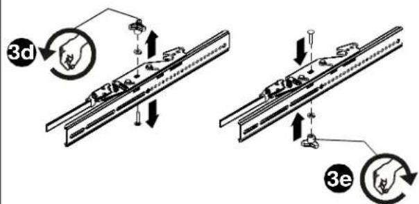
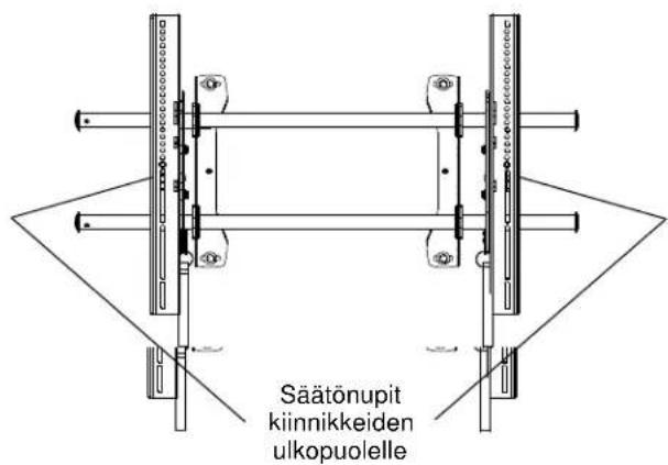
Switching Interface Brackets (Optional)
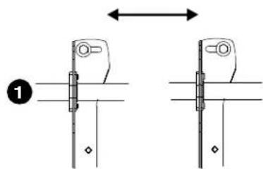
If an installation situation makes adjusting the location of interface brackets necessary, there are several options.
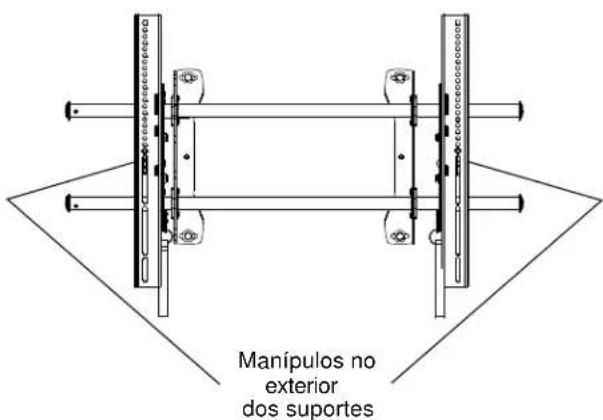
- The wall brackets may be adjusted side to side at the point of attachment.
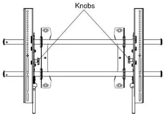
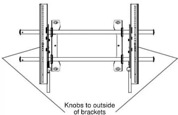
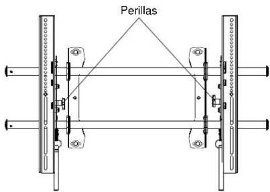
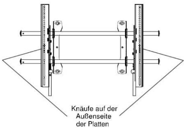
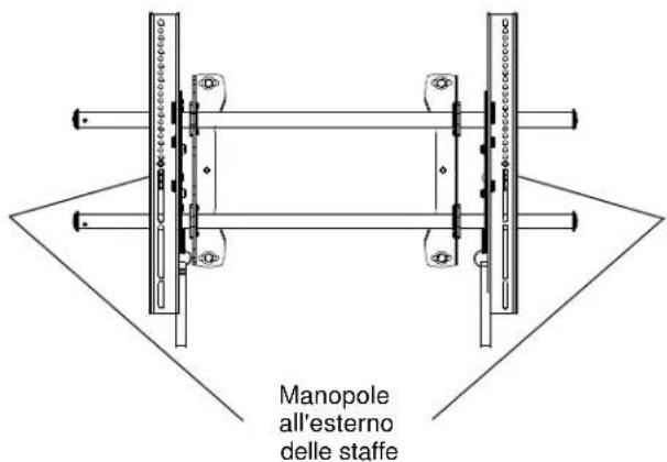
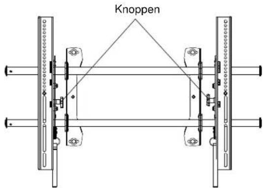
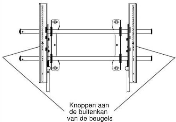
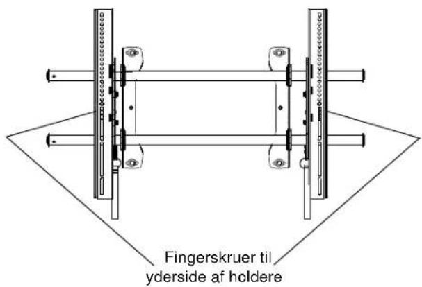
- The location of the left and right interface brackets may be switched, with the knobs on the iCLPTM2 interface brackets facing the inside of the mount.
- If necessary, the tilt interface bracket knobs may be switched to allow the interface brackets to be reversed.
a. Remove display from mount.
b. Remove interface brackets from display.
c. Hold the right interface bracket horizontally, tightly gripping it so that spacers do not move.
d. Remove the knob, washer and screw.
e. Replace the knob, washer and screw in the opposite order, with the knob on the inside of the bracket.
f. Switch the right interface bracket to the left side of the wall mount.
g. Repeat Steps 3c through 3f with the left interface bracket.
Tilting the Interface Brackets (iCLPTM2 only)
The brackets may be tilted by loosening the knob on the brackets, tilting to desired location, and tightening knob on the brackets.
5
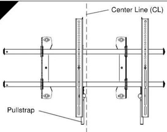

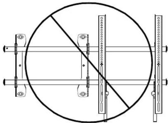
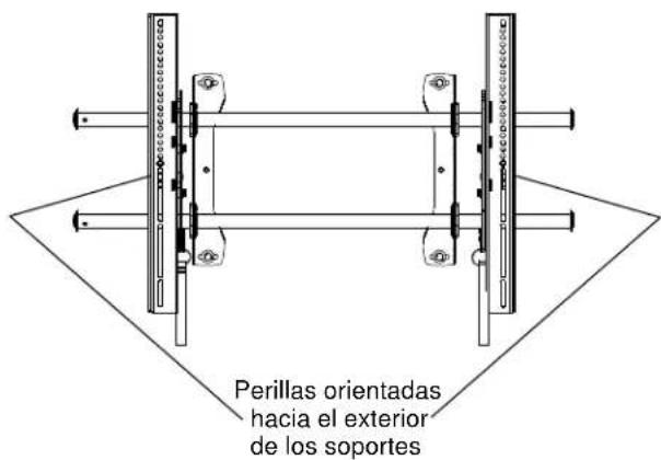
NEVER place both interface brackets to one side of the wall mount center line (CL)!
natural_image
Technical line drawing of a circular mechanical assembly with vertical supports and a diagonal line (no text or symbols)
Both interface brackets must NEVER be located to one side of the wall brackets!
Attaching Screen to Wall Mount
- Adjust Velcro® pull strap (if necessary) so it does not extend beyond bottom of screen.
NOTE: Do NOT allow both interface brackets to be located on same side of wall bracket.
NOTE: NEVER place both interface brackets to one side of the wall mount center line!
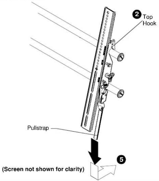
- Hang top hook of interface brackets onto the top bar of the mount.
NOTE: The screen initially installs into the "kickstand mode" to allow easy cable access.
-
Slide screen and bars to desired viewing position.
-
Route cables between wall and bars.

CAUTION: PINCH POINTS! Keep fingers, hands and cables out of pinch point areas.
- Pull downward on the pullstraps and swing inward toward wall, latching interface brackets to lower bar and locking bottom of screen to the mount.
1

natural_image
Abstract black curved arrow graphic with a numbered circle at the center (no text or symbols)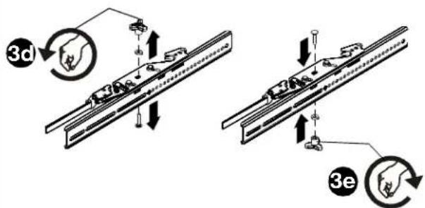
natural_image
Technical line drawing of a circular mechanical assembly with vertical supports and a diagonal cross-section (no text or symbols)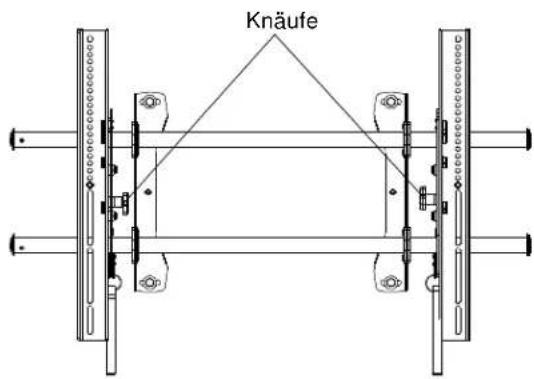

natural_image
Abstract black curved arrow graphic with a numbered circle at the center (no text or symbols)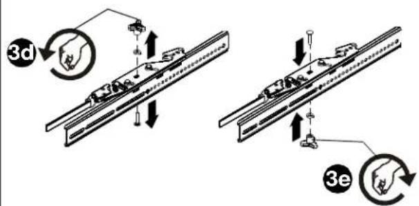
natural_image
Pure technical diagram of a circular mechanical assembly with diagonal lines and mounting brackets (no text or symbols)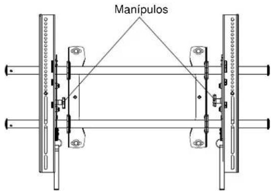

natural_image
Abstract black curved arrow graphic with number 2 at center (no text or symbols)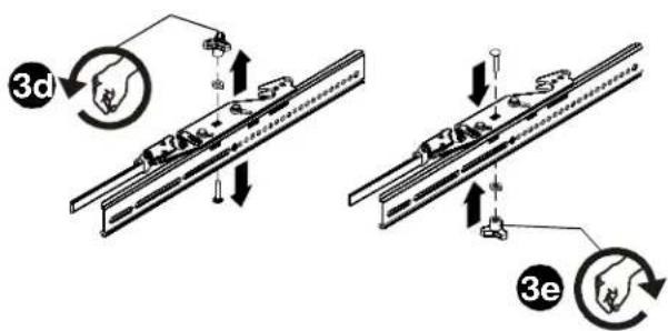
Trocar os Suportes da Interface (Opcional)
natural_image
Technical line drawing of a circular mechanical assembly with vertical supports and a diagonal line (no text or symbols)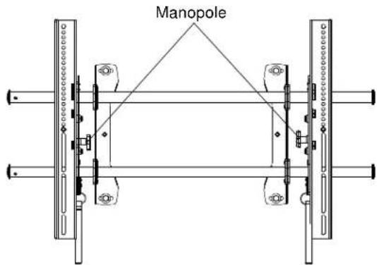

natural_image
Abstract black curved arrow graphic with a numbered circle at the center (no text or symbols)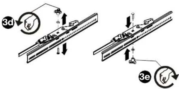
natural_image
Technical line drawing of a circular mechanical assembly with vertical supports and a diagonal line (no text or symbols)WAARSCHUWING! WAARSCHUWING VOOR
WAARSCHUWING! WAARSCHUWING VOOR

natural_image
Abstract black curved arrow graphic with a circled number 2, no text or symbols present
natural_image
Pure mechanical diagram showing a circular component with diagonal lines and mounting brackets (no text or symbols)

natural_image
Abstract black curved arrow graphic with number 2 at center (no text or symbols)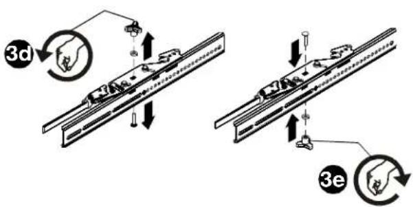

natural_image
Pure mechanical diagram showing a circular frame with diagonal lines and mounting brackets (no text or symbols)natural_image
Pure geometric lines forming an L-shape with a right-angle base and diagonal line (no text or symbols)natural_image
Pure mechanical diagram showing a circular component with vertical supports and diagonal lines, no text or symbols present.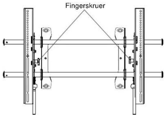

natural_image
Abstract black curved arrow graphic with a numbered circle at the center (no text or symbols)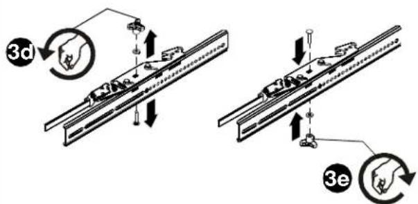
natural_image
Pure mechanical diagram showing a circular frame with diagonal lines and mounted components (no text or symbols)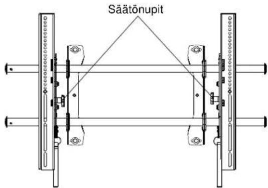
natural_image
Abstract black curved arrow graphic with a numbered circle at the center (no text or symbols)
natural_image
Pure mechanical diagram showing a circular component with diagonal lines and mounted components (no text or symbols)natural_image
Pure mechanical diagram showing a right-angled bracket with diagonal and horizontal lines, no text or symbols present.natural_image
Pure mechanical diagram showing a circular component with diagonal lines and support brackets (no text or symbols)natural_image
Pure geometric lines forming an L-shape with no text, numbers, or symbolsnatural_image
Pure mechanical diagram showing a circular component with diagonal lines and vertical supports (no text or symbols)natural_image
Pure mechanical part diagram showing diagonal lines and alignment markers (no text or symbols)natural_image
Pure mechanical diagram showing a circular component with vertical supports and diagonal lines, no text or symbols present.natural_image
Pure geometric line drawing of a structural bracket (no text or symbols)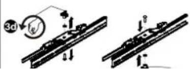
natural_image
Pure mechanical diagram showing a circular component with diagonal lines and two vertical supports (no text or symbols)natural_image
Pure geometric lines forming an L-shape with no text, numbers, or symbolsnatural_image
Pure mechanical diagram showing a circular frame with vertical supports and diagonal lines, no text or symbols present.©2009 Milestone AV Technologies. The iC Logo and StowAway are trademarks of Chief Manufacturing, a products division of Milestone AV Technologies, a Duchossois Group Company. All rights reserved Patents and patents pending. Milestone AV Technologies, Savage, MN 55378, USA 8805-
8805-000269 Rev 00
05/09