
S20 - Smartphone Bea-fon - Free user manual and instructions
Find the device manual for free S20 Bea-fon in PDF.
| Product Type | Espresso and hot beverage machine |
| Brand | Bea-fon |
| Model | S20 (S24, S26, S27, MIDI, TECNA, SYSTEM) |
| Dimensions (S24) | 380 x 320 x 465 mm (W x D x H) |
| Dimensions (SYSTEM 3) | 900 x 840 x 465 mm (W x D x H) |
| Weight (S24) | 31 kg |
| Weight (SYSTEM 3) | 76 kg |
| Power supply | Single-phase or three-phase, depending on model (see nameplate) |
| Boiler capacity | 3.9 to 12 liters depending on model |
| Water tank (S24) | 2 liters, with built-in water softener |
| Main functions | Preparation of espresso, cappuccino, tea, hot water and steam |
| Controls | Main switch, electronic keyboard for doses, steam/hot water knobs |
| Maintenance and cleaning | Daily cleaning of groups, wands and drip tray; regular descaling |
| Safety | Safety valve, thermal protection, check valve |
| Spare parts and repairability | Parts authorized by the manufacturer, intervention by qualified technician |
| General information | Professional or domestic use; do not use outdoors |
Frequently Asked Questions - S20 Bea-fon
User questions about S20 Bea-fon
0 question about this device. Answer the ones you know or ask your own.
Ask a new question about this device
Download the instructions for your Smartphone in PDF format for free! Find your manual S20 - Bea-fon and take your electronic device back in hand. On this page are published all the documents necessary for the use of your device. S20 by Bea-fon.
USER MANUAL S20 Bea-fon
First of all, thank you choosing RANCILIO.
We are confident that the product you have purchased will come up to all your expectations just as all our other products are designed to do. The product that you are about to use is the outcome of painstaking research and tests. The Rancilio's consistency assures quite sure that the equipment we have supplied you with, is the most functional, safe and satisfactory of its kind to be found on the market, as regards both its design and its efficiency. The booklet of instructions for its correct use and maintenance will help you to get the best possible service out of your machine. We trust you will find our explanations clear and we may continue, in the future, to count you among our esteemed customers.

to which this declaration relates is, according to the provisions of the specific directives:
73/23/CEE, 93/68/CEE
Direttiva Bassa Tensione - Direttiva Basse Tension - Niederspannungsrichtline - Low Voltage Directive - Direcva Baja Tension
89/336/CEE, 93/68/CEE, 92/31/CEE
it complies with the following norms:
VSR, S, Med. 78 e '95
Norme applicate - Normes appliquées - Angewandte Vorschriften - Applied standards - Normas aplicadas
Data: date: 26-03-2001
7.1. Commandes Fig.8
0-2
1/1
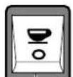
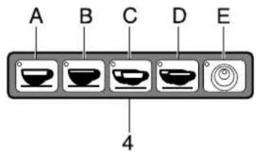
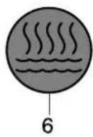
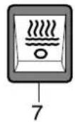
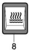
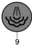
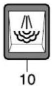
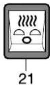
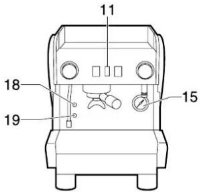
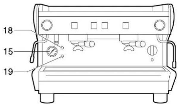
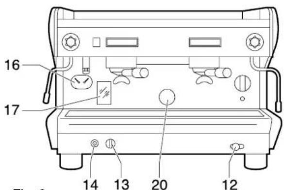
Fig. 8
These Operations are very important. They are the most important operations in the German economy.

6.3. Positionierung
The operations marked with this symbol are to be undertaken exclusively by an installation technician
The operations marked with this symbol are to be undertaken by the user.
GB ENGLISH
CONTENTS
Machine identification data 72
- General safety rules 73
2.Description 73
2.1. Specifications and composition 74
2.2.Machine equipment 77
2.3.Mechanical protective devices 77
2.4. Electric safety devices 77
2.5.Aerial noise 77
2.6.Vibrations 77
- Technical data 78
3.1.Dimensions and weights 78
4.Use 79
4.1. Precautionary measures 79
- Transport 79
5.1. Packaging 79
5.2. Inspection on receipt 79
- Installation 80
6.1.Connections to be made by the user .... 80
6.1.1.Water and gas supply 80
6.1.2. Electric supply 81
6.2.Preliminary operations 81
6.3. Positioning 81
- Setting up 82
7.1. Controls 82
7.2. Control instruments 83
7.3.Starting up 84
8.Use 85
8.1.Preparing coffee 85
8.2.Preparing cappuccino 86
8.3.Warming a beverage 86
8.4.Preparing tea,camomile,etc. 86
- Adjustments and settings of the dose 87
9.1.For S27-MIDI DE-TECNA DESYSTEM DE-SYSTEM LE models 87
9.1.1. Adjusting the dose 87
9.1.2. Adjusting the quantity of hot water .... 87
- Maintenance 88
10.1.Daily 88
10.2. Weekly 88
10.3.Periodical 89
10.3.1. Renewal of water n the boiler mod.MIDI-TECNA. 89
10.3.2.Regeneration 90
- Machines with alternative gas heater version 91
- Stopping the machine 92
- Troubleshooting 92
NAME: Coffee machine series S20
MODEL: S24 - S26 - S27 - MIDI - TECNA - SYSTEM - SYSTEM/LE
VERSIONS: S24 - S26 - S27
MIDI/DE-MIDI/CD
TECNA/DE-TECNA/CD
SYSTEM 2/DE - SYSTEM 2/CD - SYSTEM 3/DE - SYSTEM 3/CD
SYSTEM 2/DE H - SYSTEM 2/CD H - SYSTEM 3/DE H
SYSTEM 3/CD H - SYSTEM 2/DE HTS - SYSTEM 3/DE HTS
The label illustrated on the EC declaration of conformity of this instruction manual corresponds to the identification label placed on the machine Fig. 2.
Label identification:
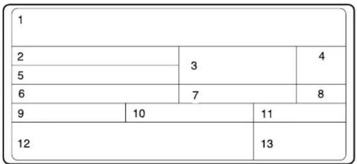
1 Manufacturer
2 Model and version
3 Voltage
4 EC conformity mark (if required)
5 Serial number
6 Boiler data
7 Machine total absorption
8 Protection level
9 Motor power
10 Heating element power
11 Frequency
12 Conformity marks
13 Year of manufacture
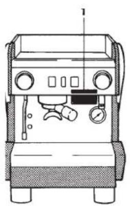
Fig. 1
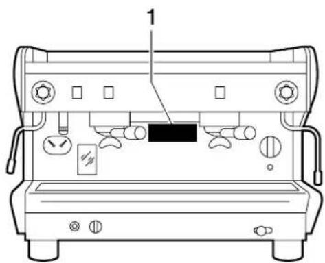
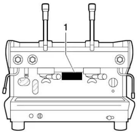
Fig. 2
Symbols

Warning signal. The instructions which refer to this signal must be followed with great care in order to avoid accidents or damage to the machine.
This manual is an integral and essential part of the product and must be delivered to the user. The warnings contained in it must be read carefully, as they supply important indications relating to the safety of installation, use and maintenance. Keep this manual for future reference.
1. GENERAL SAFETY RULES
- Don't leave the packing elements (plastic bags, polystyrene foam, nails, cardboard, etc.) within the reach of children, as these elements are potential sources or danger.
- Check that the data on the machine corresponds to that of the electrical supply network, before connecting the equipment.
Adaptors, multiple sockets and/or extensions must not be used. -
In doubt, request an accurate check on of the plant by qualified personnel. The electric system must be provided with the following safety devices:
-
efficient earth connection;
- section of conductors suitable for absorption capacity
-
efficient earth leakage protection circuit breaker.
-
Install the machine on a water repellent surface (laminate, steel, ceramic, etc.) away from heat sources (oven, cooking stove, fireplace, etc.) and in conditions in which the temperature may not go below 5^ . KEEP WARM.
- Do not leave the machine exposed to atmospheric agents or place them in damp rooms such as bathrooms.
- Do not obstruct the suction or dispersion grills and do not cover with cloths, etc.
- Keep the packed machine in a dry place, not exposed to atmospheric agents and in conditions in which the temperature does not go below 5^ . Do not stack more than three items of the same kind. Do not place heavy items on the packaging.
In an emergency, such as fire, unusual noise, overheating, etc., take immediate action, disconnecting the power and closing gas and water taps. - Only use original spare parts in order to avoid compromising the safety and proper functioning of the machine.

Erroneous installation may cause damage to people, animals and things for which the manufacturer cannot be held responsible
2.DESCRIPTION
The machines in the S20 series have been designed to prepare espresso coffee and hot beverages.
A positive-displacement pump inside the machine powers the heater in which the water is heated. By pressing the appropriate buttons, water is supplied to the spouts in the form of hot water or steam, according to needs.
In the model with an economizer, the water to be used for the beverages is supplied directly by the water supply, pressurized by the pump and immediately heated by the steam produced by the boiler.
Model S24 has an incorporated water-tank and does not, therefore, need to be connected to the waterworks. A water-softener inside the tank softens the water, filtering the calcium salts in it.
The machine consists of a steel supporting structure on which the mechanical and electrical components are fitted. These are completely covered with panels in varnished steel and stainless steel.
The beverages are dispensed at the front of the machine, where all the buttons, control devices and dispensers are to be found.
There is a cup-warming plate on the top of the machine.
2.1. Specifications and composition
mod. S24
mod. S26
mod.S27
mod. MIDI CD
mod.MIDI DE
mod. TECNA CD

mod. TECNA DE
Fig. 3
| A | B | C | D | E | F | ||
| * S24 | ok - 1 1 1 - | ||||||
| S26 | ok - 1 1 1 - | ||||||
| S27 | - | o | k | 1 | 1 | ||
| MIDI CD | ok - | 2 | 1 1 - | ||||
| MIDI DE | - | o | k | 2 | 1 | 1 | |
| TECNA CD | ok - | 2 | 1 1 | ok | |||
| TECNA DE | - | o | k | 2 | 2 | ||
| ** SYSTEM 2/DC SYSTEM 2/DC H | ok - | 2 2 | 1 - | ||||
| ** SYSTEM 2/DE SYSTEM 2/DE H SYSTEM 2/DE HTS | - | o | k | 2 | 2 | ||
| ** SYSTEM 3/CD SYSTEM 3/CD H | ok - | 3 2 | 1 - | ||||
| ** SYSTEM 3/DE SYSTEM 3/DE H SYSTEM 3/DE HTS | - | o | k | 3 | 2 | 1 | |
| *** SYSTEM/LE 1 | ok | - | 1 | 1 | 1 | - | |
| SYSTEM/LE 2 | ok | - | 2 | 2 | 1 | - | |
| SYSTEM/LE 3 | ok | - | 3 | 2 | 1 | - |
Legend:
A Semiautomatic system; manual dispensing start and stop.
B Automatic system; electronic control of coffee and hot water doses dispensed.
C N. of coffee dispensing units.
DN. of steam spouts.
EN. of hot water spouts.
F Operating with economizer.
- Incorporated water-tank and softener (does not need to be connected to the water supply.)
** Gas heated version available on request.
*** Lever operation
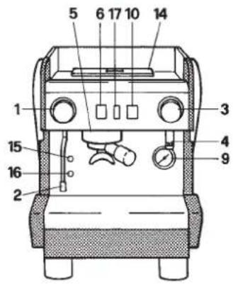
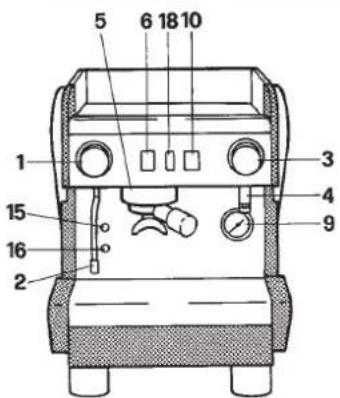
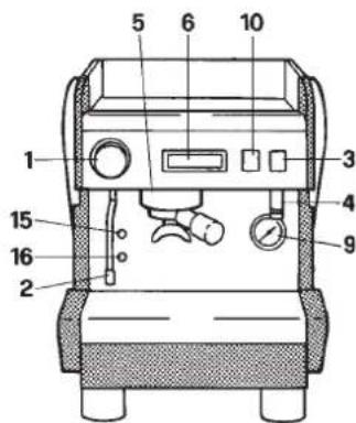
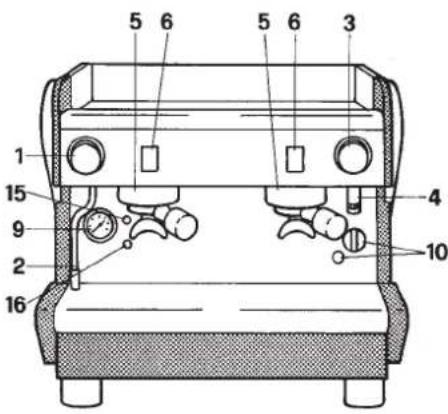
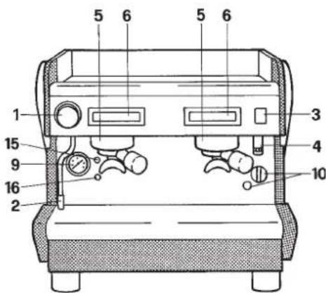
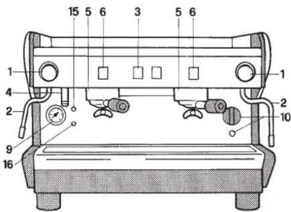
1 Steam tap
2 Steam spout
3 Hot water switch
4 Hot water spout
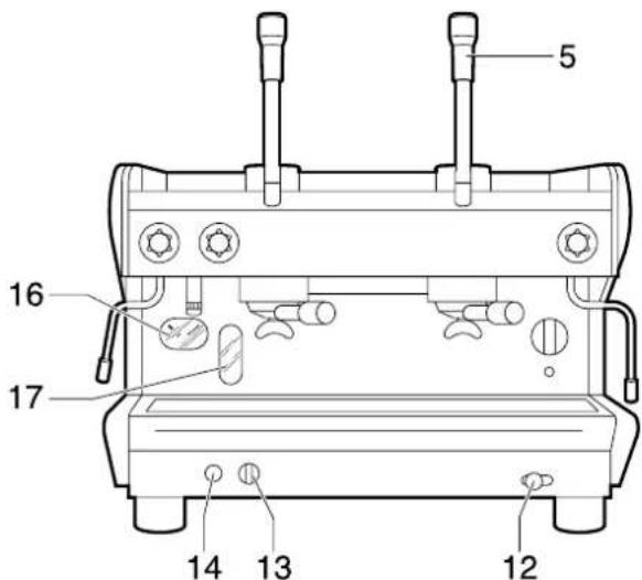
5 Coffee dispensing unit
6 Coffee dispensing button
7 Manual water supply button (only SYSTEM)
8 Level indicator (only SYSTEM)
9 Gauge
10 Power on-off switch and led
11 Gas lighter (on specific models)
12 Valved gas tap (on specific models)
13 Steam button (only on models DE/H TS)
14 Water-tank (only on model S24)
15 Water level lamp
16 Orange water supply lamp
17 Water shortage pilot light (only S24)
18 Resistor activate pilot loght (only S26)
19Group control level (only SYSTEM LE)
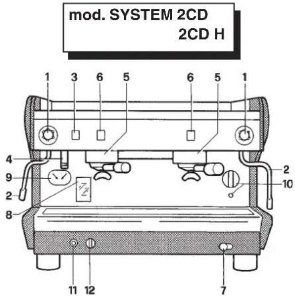
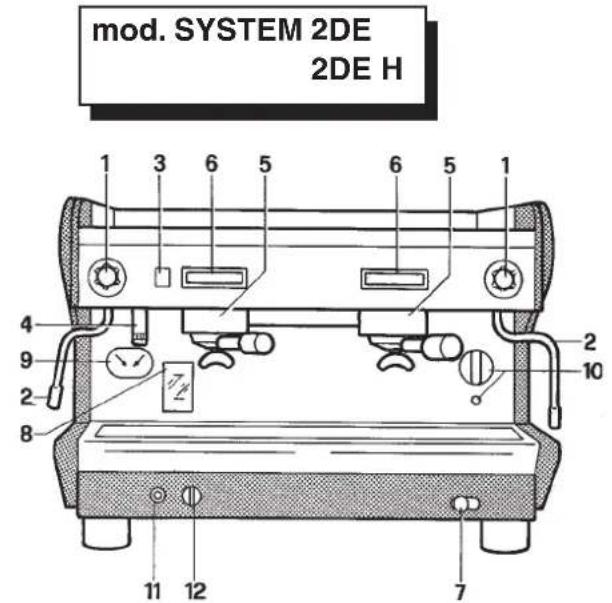

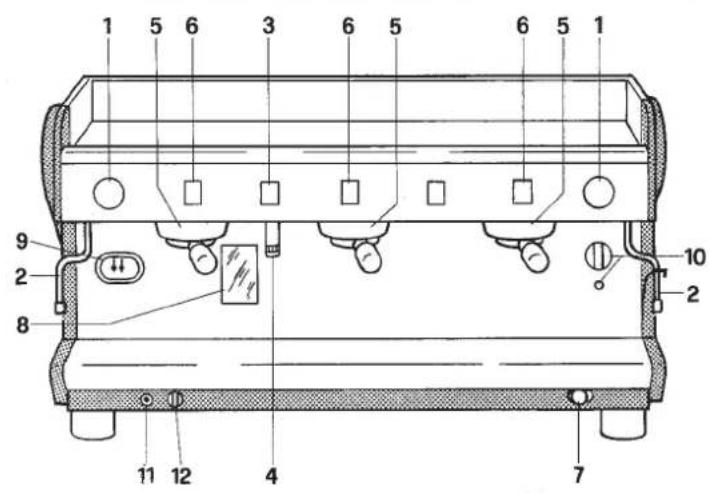
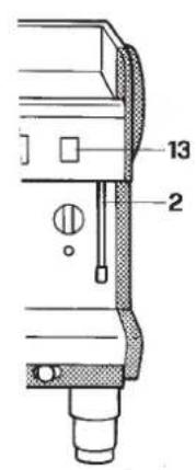
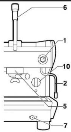

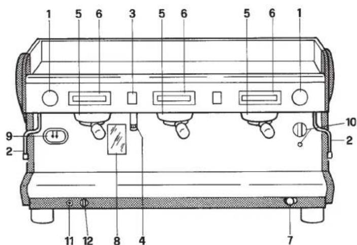
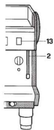
Fig. 4
2.2. Machine equipment
| S24 S26 S27 | MIDI CD TECNA CD SYSTEM 2/ CD* - CD H SYSTEM/ LE 1 - LE 2 | MIDI CD TECNA CD SYSTEM 2/ DE*-DE H/HTS | SYSTEM 3/ CD* - CD H | SYSTEM 3/ DE*-DE H/HTS SYSTEM/LE 3 | |||
| 1 dose filter holder | 1 | 1 | 1 | 1 | 1 | 1 | |
| 2 dose filter holder | 1 | 1 | 1 | 2 | 2 | 3 | 3 |
| Filters | 2 | 2 | 2 | 3 | 3 | 4 | 4 |
| Blind filter | 1 | 1 | 1 | 1 | 1 | 1 | 1 |
| 1 mt. supply pipe | - | 1 | 1 | 1 | 1 | 1 | 1 |
| 1,5 mt. supply pipe | - | 1 | 1 | 1 | 1 | 1 | 1 |
| 1,5 mt. drainage pipe | - | 1 | 1 | 1 | 1 | 1 | 1 |
| Pipe connections | - | 1 | 1 | 1 | 1 | 1 | 1 |
| Fuses | - | - | 3 | - | 3 | - | 6 |
| Doser and presser | 1 | 1 | 1 | 1 | 1 | 1 | 1 |
| Instruction manual | 1 | 1 | 2 | 1 | 2 | 1 | 2 |
| Brush | 1 | 1 | 1 | 1 | 1 | 1 | 1 |
| Wiring diagram | 1 | 1 | 1 | 1 | 1 | 1 | 1 |
| ** Cup support | - | - | - | 2 | 2 | 3 | 3 |
| *** Foot support | - | - | - | - | 4 | - | 4 |
- Models equipped with gas connections (when applied).
** Only for H and DE/H TS models
*** Only for DE/H TS models
2.3. Mechanical protective devices
The machine is equipped with the following protective devices:
complete panelling protection of all the parts subject to heat and of the steam and hot water supplier;
- cup-warmer plate supplied with a tray to collect spilt liquids;
- work surface provided with grill and tray to collect spilt liquids;
- buttons in a safe place above the dispensing area;
- expansion valve in the hydraulic system and valve on the boiler to avoid overpressure;
- nonreturn valve on the hydraulic system to avoid flowing back to the main supply.
2.4. Electric safety devices
The safety devices provided are:
- 5V low tension push buttons an the DE control key panel;
- thermal protection on the pump motor;
- gas failure thermocouple and thermocouple control thermostat automatically closing gas tap;
resistance protection thermal relai.
2.5. Aerial noise
Noise level in the work place does not usually exceed 70dB(A).
2.6. Vibrations
The machine is supplied with rubber vibration damping feet. In normal working conditions, the machine does not produce vibrations harmful to the operator and the environment.
3. TECHNICAL DATA
3.1. Dimensions and weights
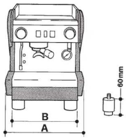
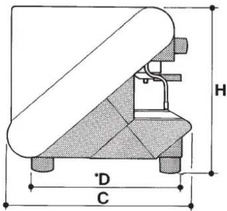
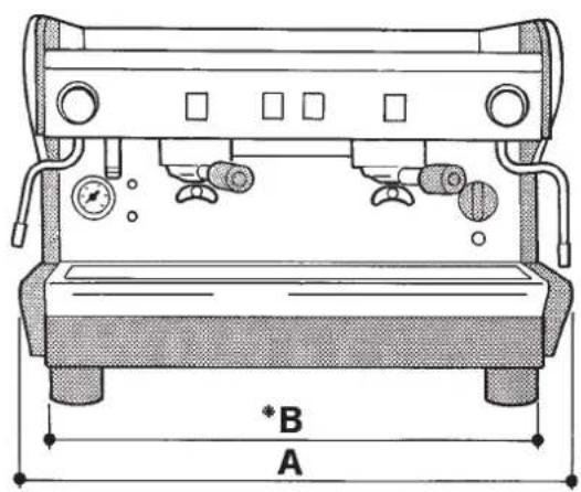
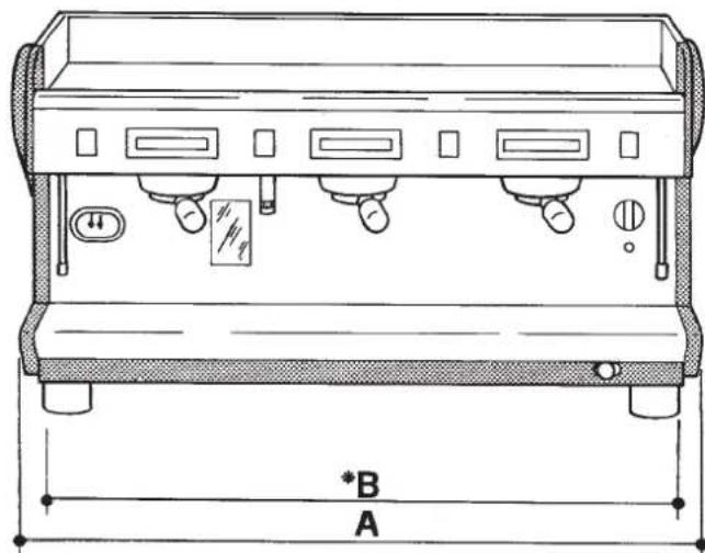
Fig. 5
| S24 S26 S27 | MIDI CD-DE SYSTEM/LE 1 | TECNA CD-DE | SYSTEM 2 CD-DE-H-HTS SYSTEM/LE 2 | SYSTEM 3 CD-DE-H-HTS SYSTEM/LE 3 | |||
| A mm | 380 | 380 | 380 | 540 660 780 900 | |||
| B mm | 320 | 320 | 320 | 480* 600* 720* 840* | |||
| C mm | 515 | 515 | 515 | 515 515 515 515 515 | |||
| D mm | 430* | 430* | 430* | 430* 430* 430* 430* | |||
| H mm | 465 | 465 | 465 | 465 465 465 465 | |||
| Boiler capacity in litr. | 3,9 | 3,9 | 3,9 | 4,9 | 11 | 12 | |
| Litres water in tankt | 2 | - | - | - | - | - | - |
| Machine weight kg | 31 | 38 | 38 | 50 | 53 | 63 | 76 |
| Water inlet | - | 3/8 | 3/8 | 3/8 | 3/8 | 3/8 | 3/8 |
| Ømm drainage | - | 14 | 14 | 14 | 14 | 14 | 14 |
| Packaging | |||||||
| No of items | 1 | 1 | 1 | 1 | 1 | 1 | 1 |
| Volume m³ | 0,18 | 0,18 | 0,18 | 0,24 | 0,28 | 0,33 | 0,37 |
| Length mm | 495 | 495 | 495 | 780 900 | 1020 | ||
| Width mm | 670 | 670 | 670 | 670 670 670 | |||
| Height mm | 575 | 575 | 575 | 700 700 700 | |||
| Gross weight kg | 35 | 42 | 42 | 54 | 60 | 72 | 86 |
- Variable in reduction

You'll find all the technical data on electric connection, on the machine identification label Fig. 1.
Machines provided with gas heating have a standard connection kit to carry out the following connections with:
- direct stiff pipe;
- copper and double cone pipe;
- rubber support.

Gas connections must be made in compliance with the safety regulations in force in the relative country.
4. USE
The machine have been designed, manufactured and protected to be used to make express coffee and hot beverages (tea, cappuccino, etc.). Any other use is to be considered unsuitable and therefore dangerous.

The manufacturer cannot be held responsible for any damage caused to people or things due to unsuitable, erroneous or irrational use of the machine.
The operator must always follow the indications contained in this manual. In the case of a failure or if the machine is not working properly, switch it off and do not attempt any direct repair. CContact the service centre.
The user must not:
- touch the hot surfaces and dispensing areas;
- place liquid containers on the machine;
- put his hands under the spouts during use;
- transport the machine or carry out maintenance operations when the plug is connected or when the machine is hot;
- wash the machine with water or steam jet;
- completely or partially immersethe machine in water;
- leave the machine exposed to heat sources;
- use the machine if the cable is damaged;
- touch the machine when his hands or feet are wet or damp;
- use the machine when there are children in its proximity;
- allow the machine to be used by children or unfit people;
- obstruct the suction or dispersal grills with cloth or any other thing;
- leave the side doors open (mod. S24);
do not use the machine when wet or very damp.
4.1. Precautionary measures
This machine may only be used with foodstuffs. It cannot be used for heating liquids or grinding any other kind of product that could damage and pollute it.

The manufacturer cannot be held responsible for damage to people or things caused by unsuitable, erroneous or irrational use.
5. TRANSPORT
5.1. Packaging
The machine is delivered in a strong cardboard box with internal protection.
The packaging bears symbols which must be observed during handling and stocking of the item.

Always keep the package in a vertical position during transport. Do not turn it over or lay it on its side and avoid bumping and exposure to atmospheric agents.
5.2. Inspection on receipt
Check that the machine received corresponds to the one indicated on the delivery note, including any accessories.
Check that it has not been damaged during transport and, if so, inform the forwarder and our customer service office immediately.

The packing elements (plastic bags, polystyrene foam, nails, cardboard, etc.) must not be left within reach of children as they are potential sources of danger. Do not dispose of the packing elements in the environment; consign them to firms authorized for their disposal.

6. INSTALLATION
The machine has feet that are adjustable in width and depth in order to allow them to stand within minimum and maximum areas (see overall dimensions according to the model).
The surface must be well levelled, dry, smooth, strong, stable and at a height of approximately 110 cm from the floor.
It does not need to be anchored to the surface and it does not require any technical operations to dampen vibrations in order to operate properly.
It is recommended to leave the area around the machine free to facilitate its use and the performance of any maintenance operations.

If the machine is wet or very damp, wait until it is completely dry before installing or using it. It is always necessary to request an accurate check by qualified service people in order to find any possible damage to the electric components.
Reserve an area near the machine for the installation of the coffee grinding and dosage machine (see relevant documentation).
The machine is usually equipped with a water softener, type DP8 or DP12, which must be connected by the user in compliance with the laws in force. Should a different softener be installed, refer to the documentation of the relevant product.
A dreg drawer should be fitted by the installer.

6.1. Connections to be made by the user.

Connections must be carried out by qualified personnel in full accordance with federal, state and local regulations.
6.1.1. Water and gas supply (Fig.6)
Connections must be installed close to the machine.
Water drainage pipe 1, having a minimum internal diameter of 30~mm equipped with a water-trap accessible for inspection.
Water supply pipe 2, with a 3/8''G cut-off tap.
Gas supply pipe 3, with a cutoff tap.

The machine with gas heating must be installed in compliance with current local laws.
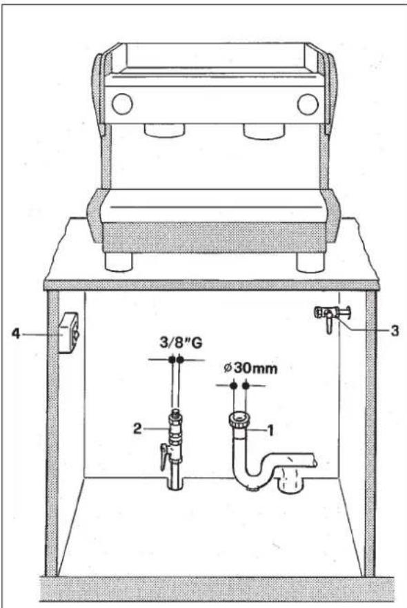
Fig. 6

6.1.2. Electricity supply
The machine is supplied ready for connection according to the required electrical specifications.
Before connecting the machine ensure that the plate details (fig. 1) comply with those of the electric distribution network.
The electrical connection cable must be directly connected to the connection provided according to current legislation. Ensure that the earthing system is efficient and in compliance with current legal requirements.
The earthing system and the lightening protection system must be realized in accordance with the provisions of current legislation.
For the supply network use a cable in compliance with standards with protective conductor (earthing wire).
For three-phase power use a cable with 5 conductors (3 phases + neutral + earth).
For single phase power supply use a cable with 3 conductors (phase + neutral + earth).
In both cases it is necessary to provide an automatic differential switch (Fig. 6) at the start of the power cable, complete with magnetic release elements in accordance with the identification plate details (Fig. 1). The contact opening must be equivalent or over 3mm .
Remember that each machine must be fitted with its own safety elements.
WARNING:

Should the power supply cable be damaged it is to be replaced by the manufacturer or by its technical assistance service or by person with equivalent qualification, in order to prevent any risks.
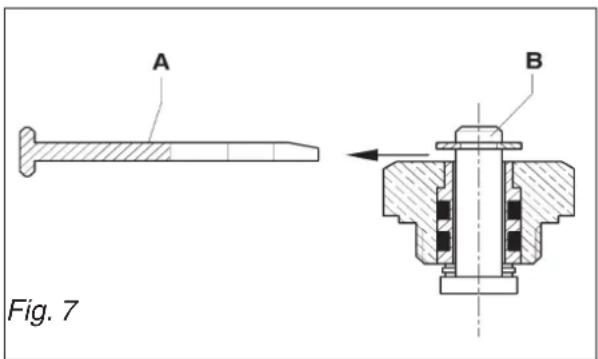
6.2. Preliminary operations
ANTISUCTION VALVE INSTALLATION
On the top of the boiler there is the antisuction valve. When installing the machine be sure to remove the plastic fork "A" and check that the pin "B" is not blocked.
This operation is very important for the correct working of the machine.


6.3. Positioning
- Place the machine on the horizontal surface previously prepared.
Before connecting, thoroughly wash the mains water pipes:
- Leave the water supply taps running at full pressure for several minutes.
- Connect to the mains water supply.
- Connect the machine to the socket.
Connect the gas pipe (model SYSTEM)
Thoroughly wash all the water pipes of the machine:
- Leave the water supply taps running at full pressure.
- Switch on main switch 1: wait until the boiler fills up to the level set.
- Switch on main switch 2 to begin heating the water in the boiler.
- Operate each unit in order to allow the water to escape for about one minute; repeat the operation twice.
- Deliver steam from the steam jets for about one minute.
- Deliver hot water for about one minute; repeat the operation twice.
- Switch off switches 1 and 2.
- Empty the water from the boiler: see point 10.3

IMPORTANT
Should the machine not deliver water for over 24 hours, wash the internal components before beginning work, repeating the operations as described above
7. SETTING UP
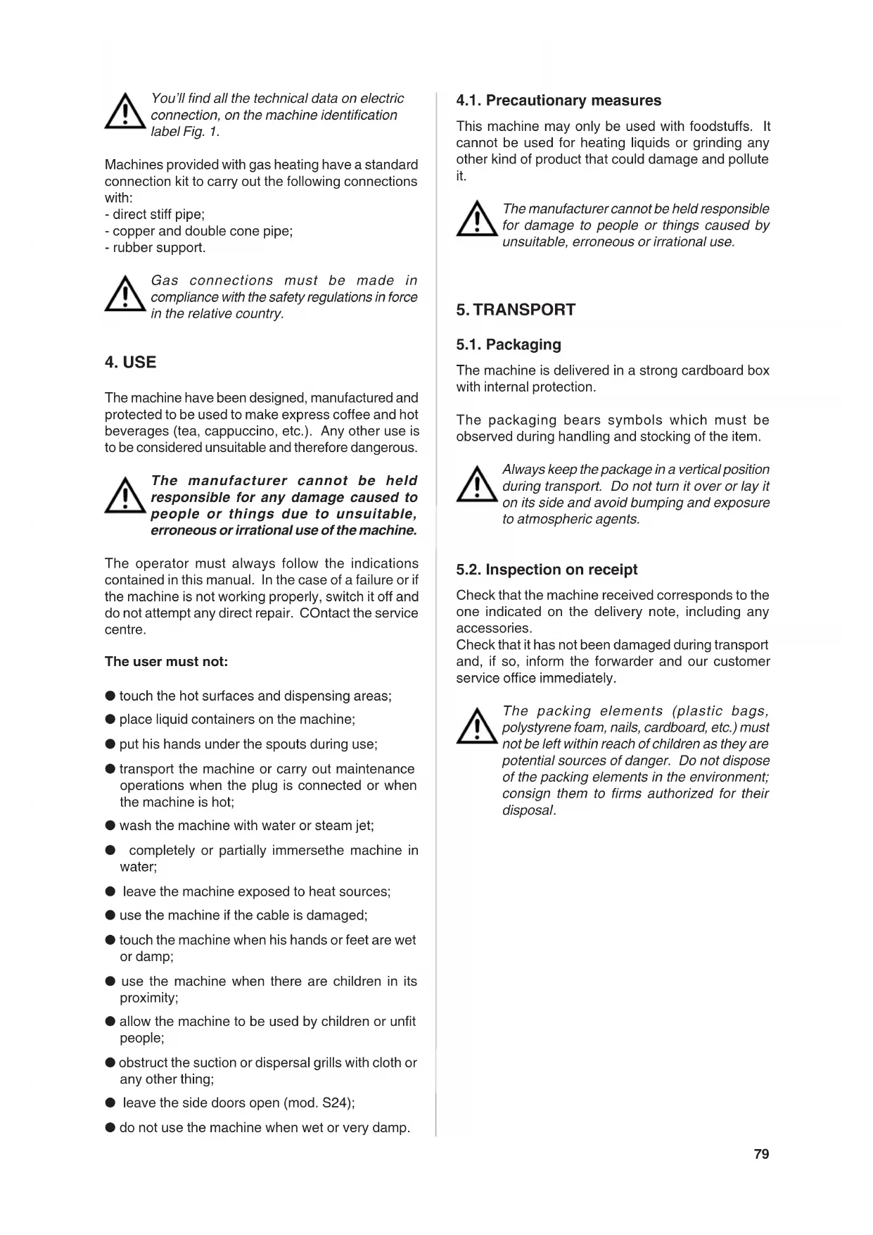
7.1. Controls Fig.8
0-2
1/1
3
6
7
8

10
21

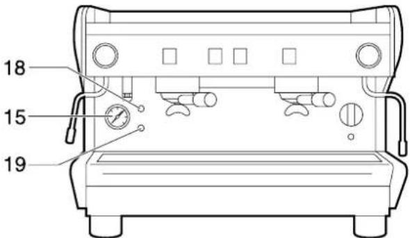
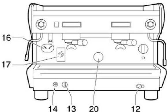
Fig. 8
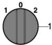
1 Main switch.
Three-position switch: O off;
1 turn on the electric power supply to the machine (apart from the boiler) and turn on the pump to fill the boiler;
2 turns on the electric power supply to the boiler heating elements.
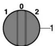
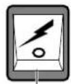
1/1Main switch.
Two-position switch with led (for mod. S24-S26-S27);
turn on the switch, led on, the machine is turned on and the pump is activated, filling the boiler with water and the heater starts to work.
2 Green pilot lamp.
When on, indicates that machine is powered (main switch on).
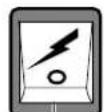
3 Coffee dispensing switch.
Two-position switch with led (mod. S24-S26SMIDI/ CD-TECNA/CD-SYSTEM/CD):
turn on the switch, led on, coffe is dispensed; turn off the switch, led off, dispensing of coffee is interrupted.
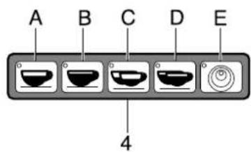
4 Electronic coffee delivery button panel.
Five buttons with relative led (mod.S27-TECNA/ DE-MIDI/DE-SYSTEM/DE):
A Press the button for a second, led on, release button; a small coffee is dispensed.
The led turns off and dispensing ceases.
B Press the button for a second, led on, release the button; a big cup of coffee is dispensed.
The led turns off and dispensing ceases.
C Press the button for a second, led on, release the button; two small coffees ar dispensed from the same unit.
The led turns off and dispensing ceases.
D Press the button for a second, led on, release the button; two big cups of coffee are dispensed from the same unit.
The led turns off and dispensing ceases.
E Press the button for a second, led on, release the button; coffee is continuously dispensed.
Press the button for a second, led off, release button; continuous dispensing of coffee ceases.
To interrupt dispensing taking place by pressing
A-B-C-D, hold button E down until the relative led turns off
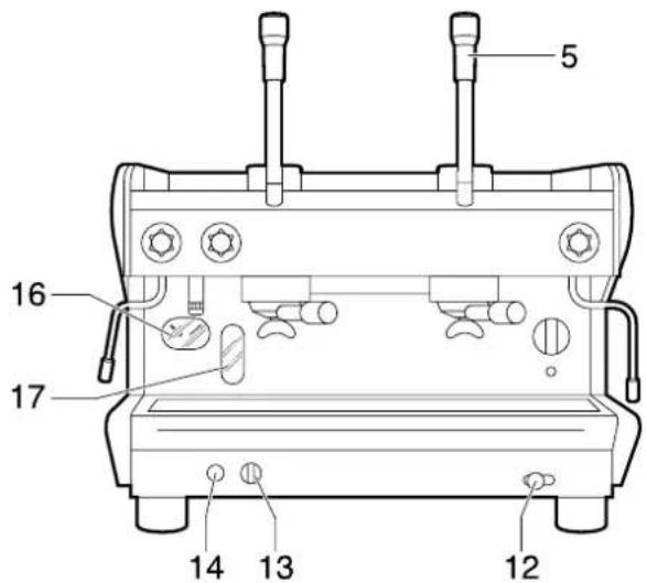
5 Coffee dispensing control lever
Take the lever and lower it to obtain the coffe dispensing.
6 Hot water supply handwheel (mod. S24-S26-MIDI/ CD).
Tap: turn a anticlockwise to open and clockwise to close.
7 Hot water supply switch (modTECNA/CD-SYSTEM/CD)
two-position switch with led: turn on the switch, led on, hot water is dispenser; turn off the switch, led off, dispensing of hot water is interrupted.
8 Dose of hot water supply switch (mod. S27-TECNA/DE-MIDI/DE-SYSTEM/DE).
Press for a second, the led lights up and a dose of hot water is obtained.
9 Steam supply handwheel.
Tap: turn in an anticlockwise direction to open and clockwise to close.
10Steam supply button (mod.DE/H TS)
See relative instructions on point 8.3.
11Orange pilot lamp (mod. S24).
When on, indicates the activation of the resistance for heating the water in the boiler.
Blue pilot light (mod.S26)
When on, indicates that the resistor for heating the water in the boiler has been activated.
12Manual filling button (mod.SYSTEM).
Press down to fill the boiler.
13Valved gas power tap (models with gas heating). Open: vertical position;
Closed: turn 90^ in clockwise direction.
14Piezoelectric button (models with gas heating).
Firing button: press down firmly to give off the spark to light the gas for the burner.
7.2. Control instruments Fig.8
15 Gauge with mobile needle on a fixed dial with a single scale and colour indicator areas (excluding SYSTEM models).
Visual control of boiler pressure.
16 Gauge with mobile needle on a fixed dial with a double scale and colour indicator areas (mod. SYSTEM).
Visual control of the pump and of the boiler pressure.
17Minimum and maximum water level indicator (mod. SYSTEM).
Visual control of water level in boiler.
18Green lamp (excluding mod. SYSTEM)
Lamp on indicates that the water level is above minimum.
19Orange lamp (excluding mod. SYSTEM)
Lamp on indicates that the water level is below minimum and that the autolevel has been activated.

If the lamp stays on, this means that the autolevel has not been activated. Ensure that the water supply tap is open, otherwise the machine must be switched off and authorized personnel must be consulted
20Control window (models with gas heating).
Visual control of lighting and functioning of the flame of the gas burner.
21Cup-warmer on/off switch (optional).


7.3. Starting up
Model S24 Fig.9
- Open the lid on the water-tank and check that the softener 22 has been inserted in the dip pipe 23;
- Ensure that the air trap 24 has been inserted in the appropriate housing;

If the air trap is not properly positioned, the machine may not heat or properly indicate the lack of water in the tank.
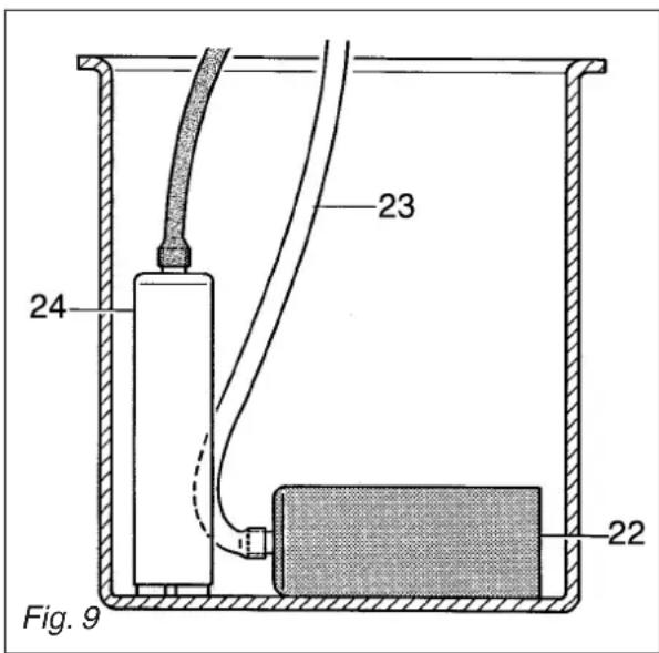
- Fill the tank with 2 litres of water and close the lid;
- Turn on main switch 1/1 ; the boiler is filled and the heater is activated;
- Wait for the machine to reach its working pressure, gauge needle 15 Fig.8 on green area, and to reach the correct thermal balance.
Model S26 - S27 Fig.8
- Turn on the water supply tap 2 Fig.6;
- Turn on the main switch 1/1 Fig. 8, the boiler is filled and the heater is activated;
- Wait for the machine to reach its working pressure, gauge needle 15 Fig.8 on green area, and to reach the correct heat level.
Model MIDI - TECNA - SYSTEM Fig.8
- Turn on the water supply tap 2 Fig.6;
- Turn the main switch 1 Fig.8 in an anticlockwise direction; the pump is activated, filling the boiler;
- When the water reaches the correct level, the pump stops; turn the main switch 1 Fig.8 in a clockwise to position 2 to begin heating the water in the boiler then turn aech one until water begins to flow from them;
- Wait for the machine to reach its working pressure, gauge needle 15 or 16 Fig.8 on green area, and to reach the correct thermal balance.
Model SYSTEM with gas Fig.8
- Turn on the water supply tap 2 Fig.6;
- Turn on the gas tap 3 Fig.6;
- Turn the main switch 1 Fig.8 in an anticlockwise direction to position 1; the pump is activated, filling the boiler;
- When the correct level is reached, the pump stops.
Turn the main switch 1 Fig.8 in a clockwise direction to position 2; - Turn the gas tap 13 Fig.8 to the vertical open position and hold down the incorporated button, at the same time repeatedly pressing hard on the piezelectric button 14 until the spark lights the gas flame (carry out this operation looking through window 20 Fig.8). Hold the tap button 13 down for approx. 30 seconds to allow the safety system to keep the flame alight. If the flame goes out, repeat the operation.

Should the flame not light up, avoid insisting and close the gas tap by turning it 90^ in a clockwise direction.
Wait until the machine reaches its working pressure, gauge needle on green area, and until the correct thermal balance is achieved.
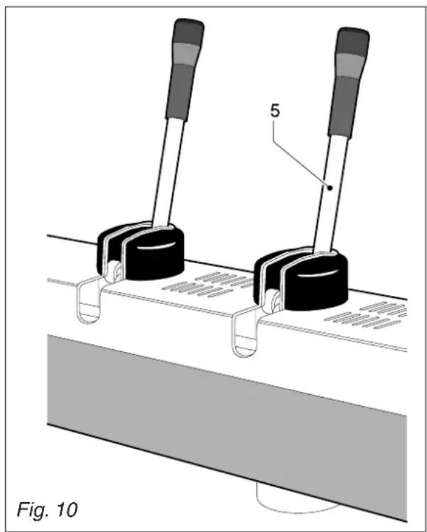
Model SYSTEM LE Fig.8
Espresso-coffee-machine with mechanical groups and fixed dosing. Bring down the group control lever (5). Wait for the outflow of some coffee drops in the cup; work the lever only initially, then let it lift up of itself.
To make 2 coffees, repeat this operation for the second time.

For the sake of safety, don't bring down the lever, if there is no coffee in the filter holder hooked on the brewing group.

8. USE
The machine has a top shelf on which the cups are kept and heated, ready for use.
This is very important to obtain good coffee as the pre-warmed cup stops the coffee from growing cold too quickly.
8.1.Preparing coffee
- Unclamp the filter-holder from the dispensing unit and knock any grouts out into the drawer especially provided for this purpose, taking care not to damage the rim of the filter.
- Use the filter for 1 or 2 coffees, according to need.
- Fill the filter with the measure of coffee, level it off and press it down gently with the presser.
- Remove any ground coffee that has stuck to the rim of the filter while pressing.

If ground coffee is left on the rim of the filter, a leaktight seal is not ensured, with consequent leaking of water and coffee grounds.
- Lock the filter-holder into the dispensing unit firmly to obtain a leaktight seal.
- Place the cups under the spouts and start pouring using control 3 or button panel 4 according to model (Fig.8).
- When the coffee has been poured, leave the filter-holder attached to the dispensing unit until the next coffee is required.

When pouring, beware of the hot parts of the machine, especially the coffee dispensing units, the steam and hot water spouts. Do not put your hands for any reason under the units and the spouts when they are operating.
The grinding of the coffee beans is of fundamental importance to the making of good coffee, and the granular texture of the resulting grounds should be such that it takes 25-30 seconds to produce the beverage. If the coffee is ground too coarsely the coffee will be pale in colour and weak in flavour, with only a very small amount of white cream, and if the grounds are too fine, the coffee will be dark with no cream. Good coffee can only be made if the beans are freshly and uniformly ground (only possible when the blades of the coffee grinder are sharp) and are then measured out into the correct quantities (roughly 6 grams per measure).
The importance of freshly ground coffee beans is due to the fact that once ground, they rapidly lose their aromatic qualities, and fats present in the beans go rancid.
8.2.Preparing cappuccino Fig.11 (excluding DE/H TS)
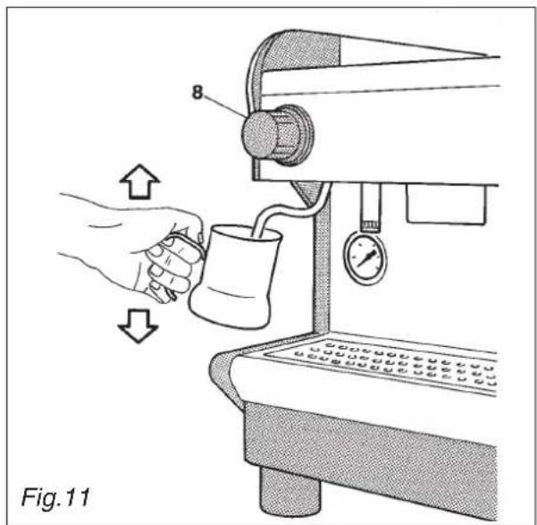
Make cup of cappuccino with the express coffee.
Use a high and narrow jug, half-filled with milk.
- Place the jug under the spout so that the nozzle touches the bottom.
- Turn on the steam tap and lower the jug so that the nozzle is almost at the surface of the milk.
- Continuously move the jug up and down so that the nozzle moves in and out of the milk, causing it to froth.
- Turn off the steam tap and pour the milk into the cup.
Immediately after carrying out this operation, clean the spout with a sponge or a clean cloth so that the milk does not dry on it. Be careful as the the spout is hot and may burn your hand.
8.3. Heating a beverage
- Immerse the steam spout into the liquid to be heated;
Gradually turn on the steam tap 9 o 10 Fig.8;the steam that bursts in the liquid heats it to the desired temperature. - Turn off the steam tap when the desired temperature has been reached.
Immediately after carrying out this operation, clean the spout with a sponge or clean cloth. Be careful as the spout is hot and may burn your hand.
Version De/H TS/LE
Use a high and narrow, half-filled jug (at least half a litre)
- Place the jug under the spout so that the nozzle touches the bottom.
Press the steam button 10 Fig.8.
- When the programmed temperature is reached, steam is no longer emitted.
To manually continue the heating process, the steam button must be held down.
The heating phase programmed can be interrupted at any moment by pressing the same steam button.
In the order to obtain a uniform temperature the steam spout and relative temperature sensor on the spout must be kept clean. They should be cleaned immediately after the heating process with a clean, slightly damp cloth
The temperature can be programmed by the technician between 54^ (130^) and 85^ (185^)
These is only one setting, valid for both steam spouts.
Delivery time must in no case exceed 5 minutes.
The user must be very careful when carrying out this operation because, as soon as the steam button is pressed, steam is emitted at full pressure from the spout.
Do not put your hands under the spout while steam is being emitted.
8.4.Preparing tea, camomile, etc.
- Place the jug under the hot water spout and use the delivery control according to the model (Fig.8). When the desired quantity has been obtained, turn off the switch.
Add the beverage desired.
Models S27 and DE
For these models, hot water is dispensed in specific measures (see paragraph 9, adjusting the dose of hot water).
To dispense hot water in different quantities, proceed as follows:
- Hold down the delivery control 4-E Fig.8 for at least four seconds then release the button; the machine continuously delivers water.
- When the desired measure has been obtained, press the button E again to interrupt delivery.
When the dose of hot water is being delivered electronically, delivery can be interrupted by pressing the button E.
When purified water is used, these beverages often assume a darker colour.
Should the user prefer a lighter coloured drink, draw fresh water from an ordinary tap and proceed with the heating phase as described in point 8.3.
9. ADJUSTMENT AND SETTING OF THE DOSE (where available)
9.1. Models S27 - MIDI DE - TECNA DE - SYSTEM DE
It is possible to adjust the dose of coffee and hot water dispensed by electronically controlled models.
9.1.1. Adjusting the dose
The quantity of coffee and hot water dispensed can be adjusted using the button panel or the hot water controls.
1 Press the button E on any button panel and hold it down for 8-10 seconds until water stops flowing from the dispensing unit and the led of the continuons button on the first button panel on the left begins flashing.
2 It is necessary to act as to make 1 or 2 cups in order to reach the correct coffee amount adjustment in the cup.
3 Put the filter-holder (with ground coffee) on the left unit and the cup under the spout.
4 Operate the selected button (i.e. button A for one small cup).
5 One the required coffee amount in the cup has been reached, press the stop button E. Coffe will stop pouring and the microprocessor will store the dose.
6 Press the continuous button E again; the led will go out and the machine will store the new quantity.
7 Make the coffee and check the cup amount in order to check that programming is correct.
If some doses have to be changed (B-C-D), once at point 5 repeat the instructions in points 3-4-5 for each dose, remembering to use the filter-holder with relevant filter and freshly ground coffee.
Then carry out point 6 and repeat point 7 to check all changed doses.
If all units are to be programmed with the same doses, the selection of coffee doses is finished. If the dosage of another unit is to be changed (1-2-3-4 doses), proceed as indicated in the above-mentioned point 1-7, using only the button panel of the selected unit.
9.1.2. Adjusting the quantity of hot water
Proceed as follows:
1 Press the continuous E button on any button panel and hold down for 8-10 seconds until water stops flowing from the dispensing unit and the led of the E button on the first button panel on the left starts flishing. The machine is ready to accept quantity variations.
2 Put a cup or a jug to receive the water under the water spout.
3 Push the delivery button 8.
4 Once the required amount is reached, press the button 8 again. Water will stop pouring and the microprocessor will store the dose.
5 Once adjusted, press the stop-continuous button E on any button panel; the led will go out and the machine will store the new quantity.
6 Pour out doses of hot water to check that programming is correct.
WARNING!
The amount of hot water dispensed can be controlled by proceeding as follows:
- press the hot water control button 8 and hold down for at least 4 seconds; when the button is released, the machine will dispense water continuously.
to manually stop dispensing, press the water control button 8 again when the required amount has been dispensed.
To stop dispensing the measured amounts of hot water, press the water control button 8.

10. MAINTENANCE

Maintenance operations have to be carried out when the machine is off and cold and the plug is disconnected. Some particular operations have to be effected when the machine is operating.
Do not clean the machine by using metal or abrasive devices, such as steel wool, metal brushes, needles, etc. or general detergents (alcohol, solvents, etc.)
When necessary, use special detergents for coffee machines that can be bought in specialized service centres.
10.1.Daily
Use a clean cloth or sponge that does not leave hairs or fluff (preferably cotton or linen).
- Carefully clean the outside surface, following the grain of the satin finish on the parts in stainless steel.
- Remove the filter-holders 1 and filters 2 and clean off the coffee incrustations. Rinse in hot water to dissolve the greasy coffee deposits.
- Clean the delivery heads and seals on the dispensing units.
- Clean the steam and hot water spouts, check that the nozzles are not encrusted (if they become encrusted, be careful not to deform or damage them).
- Clean the spray units and the seals under the casing of the delivery units using the special brush supplied
- Remove the filter-holders of the machine and remove the filters and the clamp which secures the filter, use a brush to remove any coffee deposits and rinse with hot water in order to dissolve any grease deposits.
10.2. Weekly

Operations to be carried out with the machine operative and under pressure.
- Place the supplied blind filter in the filter-holder, put in a spoonful of detergent in powder for coffee machines and fit the filter-holder in the unit to be cleaned.
- Press the coffee dispensing button and draw water for approx. 30 seconds.
- Stop and start dispensing several times until clean water comes out of the discharge unit tube.
- Remove the filter-holder, take out the blind filter and insert a normal one. Replace the filter-holder on the unit and rinse by drawing water several times.
Make a coffee to eliminate any unpleasant taste.
Model S24

Operation to be carried out when the machine is off and cold and the plug is disconnected.
- Remove the lid on the water-tank;
- Remove the air trap 24 and softener 22 (Fig.9);
Take out the water-tank, empty and clean it; - Thoroughly rinse the water-tank and replace it in the machine;
- Place the air trap in its guide and the softener horizontally on the bottom of the water-tank;
- Fill the tank with clean water and close the lid.

If the air trap is not in the correct position, the machine cannot heat or indicate a lack of water in the tank.
Models S24 - S26 - MIDI CD

Operation to be carried out immediately after the machine has been turned off when there is still some pressure.
- Using the hot water tap 6, drain off all the water;
- Turn off the tap and refill as described in paragraph 7.31
Models SYSTEM CD -LE

Operation to be carried out while there is still some pressure in the machine.
- Drain the water from the boiler (approx. four litres) using the hot water tap 7;
- Wait for the machine to te-establish its correct thermal balance before use.
Models S27 - MIDI DE - SYSETM DE

Operations to be carried out with the machine operative and under pressure.
Prepare a container that can hold at least two litres od water (four litres dor model System) and place it unter the hot water spout.
Hold down the delivery button 8 for at least four second. When this button is released, the machine will deliver water continuously
After two litres have been drawn off (four litres for the model System), press the delivery button again to stop dispensing.
- Wait for the machine to re-establish its correct thermal balance before use.
Cleaning the filters and delivery heads

Operation to be carried out when the machine is off and cold.
Prepare a solution of 4 sachets of detergent powder Code 69000124 dissolved in a litre of boiling water in a stainless steel, plastic or glass container (NOT ALUMINIUM OR IRON).
- Remove the filters and immerse them with the filter holders in the prepared solution, leaving them for at least 20/30 minutes (all night is better).
- Remove them from the container and rinse them thoroughly in running water.
- Remove the cup rack 1 (Fig.13), slide out the drip tray and clean them both.
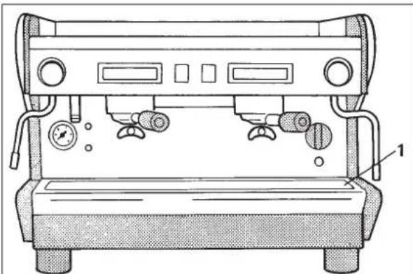
Fig. 13
- Check and clean the drainage pump 1 (Fig.13), removing any sludge with the help of a spoon.
10.3. Periodical maintenance
Models TECNA CD - TECNA DE
Have been fitted with economizers which do not draw water from the boiler to make hot water, the water in the boiler need only to be renewed from time to time.
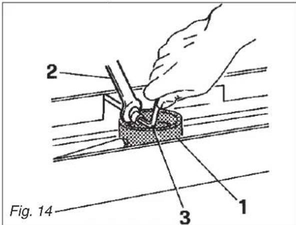

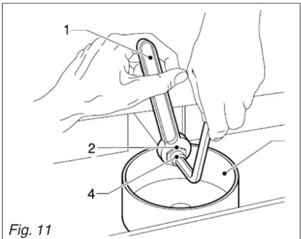
10.3.1. Renewal of water in the boiler

Models MIDI - TECNA
To be carried out only by qualified personnel.
- Turn off the machine and wait for the pressure in the boiler to diminish (gauge needl on "0").
Using a spanner firmly hold 1 the outlet pipe 2 Fig.14 situated about the drainage sump while loosening the hexagonal sealing screw 3 by 3 turns at the most. - Drain off the water and tighten the screw 3.
- Refill the boiler (paragraph 7.3.).
10.3.3. Regeneration
Model S24

Operation to be carried out when the machine is off and cold and with the plug disconnected.
To be effected after the consumption of approx.15 litres of water (average hardness calculated as 35 degrees on the French scale) or at least once a month.
Prepare a solution in a glass of water adding three teaspoons of fine salt (the salt must be properly dissolved).
- Drain the water-tank, see point 10.2.
- Slide the softener 1 Fig.15 off the rubber tubing 2 and turn it over.
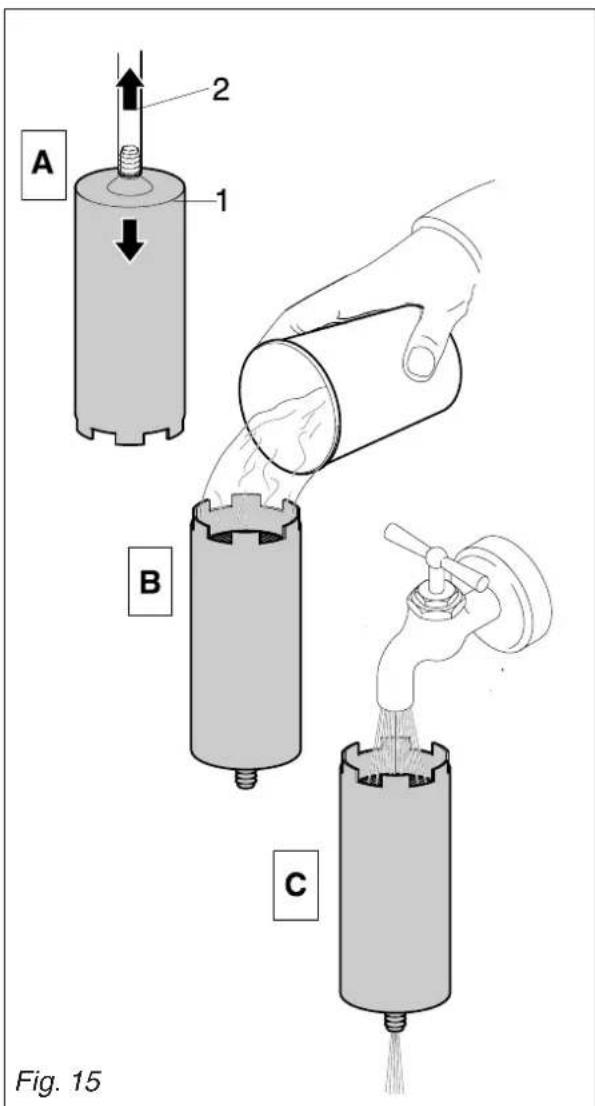
Pour the solution through the filter and the resin, letting it flow down freely.
Wait about 5 minutes, then hold the softener under a tap and rinse it with water. When the water coming out of the softener is no longer salty, the resins are regenerated and the softener is ready for use once again.
- Put the softener back on the rubber tube and replace it horizontally on the bottom of the tank.
On completion of this operation, the machine can be started up again by repeating the procedure described in paragraph 7.3.
Softener DP2 - DP4
Regenerate the water softener within the time-limits specified for the softener as follows:
DP2
nr.1 regeneration per month for 500 coffees/day; nr.2 regenerations per month (once a fortnight) for 1000 coffees/day.
DP4
nr.1 regeneration per month for 1000 coffees/day; nr.2 regenerations per month (once a fortnight) for 2000 coffees/day.
This table has been drawn up according to a water hardness of 25 degress calculated on the French scale.
See the documentation included with the softener for the instructions for use.
11. MACHINES WITH ALTERNATIVE GAS HEATER VERSION

N.B. Installation of the machine and any adjustment or adaptation to the type of gas should be done by a technically qualified person.

The machine leaves the factory all set for use in liquid gas (GPL).
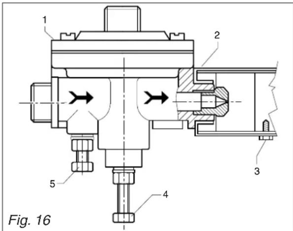
The gas regulator (1) is therefore fitted with the appropriate injector shown in the table below:
| Model | Nominal thermic capacity | GPL G30 - 29 mbar | Natural gas G20 - 20 mbar |
| 2-3 Gr. | 2,5 KW (2150 Kcal/h.) | 75 102 |
The primary air intake regulator (2) is set with the reference notch showing "GPL" corresponding to the fixture screw (3).
The flame is regulated (minimum and maximum) to suit this type of gas.
If the machine is to be used with a different type of gas, it will be necessary to replace the injector in accordance with the above table and to rotate the primary air regulator (2), which, in the case of natural gas, will have to be set with the reference notch showing "N" corresponding to the securing screw (3).
To do this, it will of course be necessary to loosen the securing screw (3) and to tighten it again after rotating the primary air intake regulator (2).
Connections to mains gas, from the gas tap available in the room to the valve fitted on the machine, must be carried out in accordance with the regulations in force, using a flexible pipe or a rigid pipe of soft copper.
In the latter case, the special rubber-pipe fitting in connected tightly to the valve by means of the biconical nozzle and securing nut supplied.
The flexible pipe is fitted over the end of the mains outlet and secured with the metal strip supplied.
Alternatively, the soft copper pipe can be connected up, again using the special biconical nozzle and the appropriate nuts, directly to the valve.
Once the machine has been connected up to the gas main, and after filling the boiler up with water in accordance with the instructions in the booklet ("INSTRUCTIONS FOR USE AND MAINTENANCE"), the burner can be lit in the following manner:
- Open the gas exclusion tap.
- Press on the gas valve knob, on the machine rotate it 90^ anti-clockwise, and keep it pressed in. At the same time, press the piezoelectric lighter one or more times - the lighter knob bears a symbol resembling a spark - until the burner lights up.
- Wait about 20 seconds, then release the valve knob and the burner should stay lit - the flame is visible through the special hole in the panel behind the dispenser units.
N.B.
Should the burner not light up, do not persist, but release the valve knob, and then check that lighter spark on the burner is in order and about 5 mm long.
Should the flame go out when the valve knob is released, check the position of thermocouple and the circuit connected to it.
The flame should be bright blue; if not, slightly regulate the primary air intake (2) until the desired effect is achieved.
Wait until the machine reaches the correct pressure, according to instructions. Otherwise, adjust the gas pressure regulator, which has two regulating screws. The one that protrudes more (4) serves to regulate the boiler's operating pressure, while the other (5) serves to set the flame at the minimum.
When the machine is pressurized, check to see that the minimum flame is correct by adjusting the screw (4) if necessary; after loosening the locking-nut, unscrew the screw until it feels loose (the main gas-pipe is closed), and check whether, under these conditions, the low flame remains lit, thus acting as a pilot.
If the flame is too high, it will be necessary to regulate screw (5), turning it slightly clockwise, of course after having loosened the locking-nut. If, on the contrary, the flame tends to go out, then regulate screw (5) by turning it anti-clockwise, until a very low, but constant flame is obtained. Having achieved this correct adjustment of the minimum flame, hold the screw still and lock it with the locking-nut.
Then rotate the screw (4) clockwise until there is a there is a high flame, and wait for the boiler to reach the desired operating pressure: if the flame dies down before reaching the required pressure, tighten screw (4) further; if the flame dies down at a higher pressure, then unscrew the screw.
Check once or twice by opening the steam tap to release the pressure in the boiler, then hold screw (4) still and lock it with the locking-nut.
12. STOPPING THE MACHINE
A - Temporary stop
- Carry out cleaning and maintenance operations.
- Wind up the cable and fasten it to the machine with sticky tape.
- Cover the machine and place it in a dry room. Do not leave it exposed to atmospheric agents and do not allow it to be touched by children or unift persons.

To disconnect from the main power supply, consult qualified personnel.
B - Definitive stop
- Besides carrying out the operations necessary for a temporary stop, cut off the cable, pack the machine in cardboard, polystyrene or other packing material and consign it to firms authorized for its disposal or to second-hand goods dealers.
13. PROBLEMS AND REMEDIES

Check operations to be carried out by the user with the plug disconnected.
For any type of problem or inconvenience not specifically indicated, disconnect the plug and contact our service centre without attempting any direct repairs.
A) The machine does not start:
- check that the plug is connected;
In case of power failure wait for the power to return and check if the earth leakage protection circuit breaker or the main switch is on;
- check the condition of the plug and the supply cable; if damaged have them replaced by qualified personnel.
B) There is water under the machine:
- check that the drainage tray is not obstructed.
C) Slow dispensing:
- check that the filters and delivery heads are clean;
- check that the coffee is not too finely ground.
D)Irregular steam delivery:
- check that the nozzles are not obstructed.
ITALIANO 5-26
F FRANCAIS 27-48
D DEUTsCH 49-70
GB ENGLISH 71-92
E ESPANOL 93-114
SCHEMI ELETTRICI
SCHEMAS ELECTRIQUES
SCHALTPLANE
WIRING DIAGRAMS
ESQUEMAS ELECTRICOS 117-135
Feeding electrovalve
Measured water electr.
Economizer electrov.
Group Electrovalve
Steam eltrovalve
Water switch
Coffee switch
Economizer switch
Main switch
Orange - automatic level
water filling
Green - water at level
Warning light
Clamp
Motor Pump
Pressure
Water push-button
Economizer push-button
Pressure level
Push-button panel
Boiler Heating Resistance
Pump relais
Heating light
Water lack indicator
Levelfeeler
Save resistance
Earth
Thermostat
Blue
White-blue
White-yellow
White
White-black
White-red
Yellow
Yellow-green
Brown
Black
Red
Green
B
Transducer autonivel
Cedula electronica
Contador volumetrico
Electrovalvula agua
Electrovalvula carga
Espia interruptor general
Borne
Motor bomba
Presostato
Pulsante agua
GB Reserved property.
Partial or total reproduction of this manual is forbidden without written authorisation of RANCILIO S.P.A..
RANCILIO reserves the right to effectuate, in any given moment, any modifications which are considered necessary.
E Propriedad restrada.


- First of all, thank you choosing RANCILIO.
- 73/23/CEE, 93/68/CEE
- 89/336/CEE, 93/68/CEE, 92/31/CEE
- VSR, S, Med. 78 e '95
- Commandes Fig.8
- Positionierung
- GB ENGLISH
- CONTENTS
- Symbols
- GENERAL SAFETY RULES
- 2.DESCRIPTION
- Specifications and composition
- Legend:
- Mechanical protective devices
- Electric safety devices
- Aerial noise
- Vibrations
- TECHNICAL DATA
- Dimensions and weights
- USE
- The user must not:
- Precautionary measures
- TRANSPORT
- Packaging
- Inspection on receipt
- INSTALLATION
- Connections to be made by the user.
- Water and gas supply (Fig.6)
- Electricity supply
- WARNING:
- Preliminary operations
- ANTISUCTION VALVE INSTALLATION
- Positioning
- IMPORTANT
- SETTING UP
- Controls Fig.8
- Control instruments Fig.8
- Starting up
- Model S24 Fig.9
- Model S26 - S27 Fig.8
- Model MIDI - TECNA - SYSTEM Fig.8
- Model SYSTEM with gas Fig.8
- Model SYSTEM LE Fig.8
- USE
- 8.1.Preparing coffee
- 8.2.Preparing cappuccino Fig.11 (excluding DE/H TS)
- Heating a beverage
- Version De/H TS/LE
- 8.4.Preparing tea, camomile, etc.
- Models S27 and DE
- ADJUSTMENT AND SETTING OF THE DOSE (where available)
- Models S27 - MIDI DE - TECNA DE - SYSTEM DE
- Adjusting the dose
- Adjusting the quantity of hot water
- WARNING!
- MAINTENANCE
- 10.1.Daily
- Weekly
- Model S24
- Models S24 - S26 - MIDI CD
- Models SYSTEM CD -LE
- Models S27 - MIDI DE - SYSETM DE
- Cleaning the filters and delivery heads
- Periodical maintenance
- Models TECNA CD - TECNA DE
- Renewal of water in the boiler
- Models MIDI - TECNA
- Regeneration
- Softener DP2 - DP4
- DP2
- DP4
- MACHINES WITH ALTERNATIVE GAS HEATER VERSION
- STOPPING THE MACHINE
- A - Temporary stop
- B - Definitive stop
- PROBLEMS AND REMEDIES
Brand : Bea-fon
Model : S20
Category : Smartphone