A-S1000 - Audio Amplifier YAMAHA - Free user manual and instructions
Find the device manual for free A-S1000 YAMAHA in PDF.

User questions about A-S1000 YAMAHA
0 question about this device. Answer the ones you know or ask your own.
Ask a new question about this device
Download the instructions for your Audio Amplifier in PDF format for free! Find your manual A-S1000 - YAMAHA and take your electronic device back in hand. On this page are published all the documents necessary for the use of your device. A-S1000 by YAMAHA.
USER MANUAL A-S1000 YAMAHA
HiFi Began with Yamaha
Yamaha's involvement with and passion for music goes back more than a century, to when we built our first reed organ in 1887. Now we are the world's leading producer of pianos and other musical instruments, and are involved with music in many other ways as well. We manufacture professional recording equipment, we design concert halls and we assist artists at concerts with set up and sound tuning.
This knowledge and experience benefits our production of audio components in many ways. We introduced our first HiFi (High Fidelity) turntable in 1955. Thereafter we were one of the first to offer mass-produced, high quality audio equipment, and introduced many legendary stereo components.
We hope you enjoy the genuine HiFi experience of Yamaha Natural Sound.

1922: We introduced a high-quality handwound phonograph.
Since 1955, we have released many HiFi components, including turntables, tuners, integrated amplifiers, control amplifiers, power amplifiers and speakers.
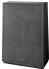
NS-20 Monitor Speaker
CA-1000 Integrated Amplifier
Featuring A-Class operation, the CA-1000 set the standard for integrated amplifiers.
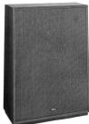
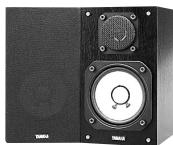
NS-690 Monitor Speaker
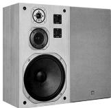
NS-1000M Monitor Speaker
A truly legendary speaker still revered by HiFi enthusiasts
B-1 Power Amplifier
An innovative power amp that used FETs in all stages
C-2 Control Amplifier
Received top prize at the Milan International Music and HiFi Show.
NS-10M Studio Monitor Speaker
Became of the most popular studio monitors in the world.
A-1 Integrated Amplifier
PX-1 Turntable
Yamaha's first linear tracking turntable
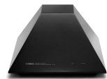
B-6 Power Amplifier
Pyramid-shaped power amplifier with X power supply and X amplifier
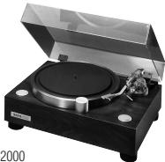
GT-2000/L Turntable
Ultra-precise heavyweight player embodying GT concept
CD-1 CD Player
First CD Player introduced in 1983
B-2x Power Amplifier
MX-10000 Power Amplifier and
CX-10000 Control Amplifier
Amplifier that redefined the capabilities of separate components
100th anniversary model
AX-2000 Integrated Amplifier
High S/N ratio (128 dB), digital direct function equipped
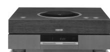
GT-CD1 CD Player
Top-loading type player with integrated separate structure
MX-1 Power Amplifier and CX-1 Control Amplifier
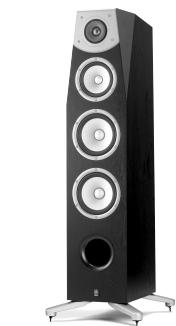
Soavo-1 and Soavo-2 Natural Sound Speaker Systems
A-S2000 Stereo Amplifier and
CD-S2000 Super Audio CD Player
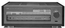
A-S1000 Stereo Amplifier and
CD-S1000 Super Audio CD Player
NS-20
NS-690
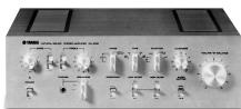
CA-1000
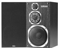
NS-1000M
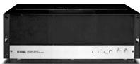
B-1
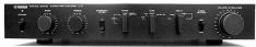
C-2
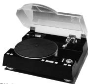
PX-1
NS-10M
B-6
GT-CD1
AX-2000
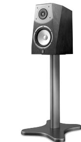
Soavo-2
A-S1000
Floating balanced circuit design
The perfectly symmetrical, fully new floating balanced power amplifier maximizes the performance of the analog amplifier.
Parallel volume and tone control
Four independent high capacity power supplies
Horizontally symmetrical structure
Phono amplifier with fully discrete structure
Newly developed heavyweight feet to suppress vibrations
Supplied accessories
Please check that you have received all of the following parts.
Remote control
- Batteries (AA, R6, UM-3) (× 2)
Power cable
Safety brochure
Contents
Controls and functions. 6
Connections. 14
Specifications 20
Troubleshooting 24
About this manual
- indicates a tip for your operation.
This manual is printed prior to production. Design and specifications are subject to change in part as a result of improvements, etc. In case of differences between the manual and the product, the product has priority. - The color of images in this manual may vary from the original.
- Read the "Safety brochure" before using this unit.
A-S1000
Controls and functions
In this chapter, you will learn the controls and functions of A-S1000.
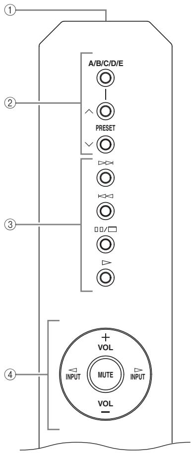
Front panel (left side)
YAMAHA
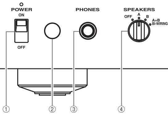
① POWER
Press upward or downward to turn on or off this unit.
中
The POWER indicator above lights up when this unit is turned on.
Notes
- If the POWER indicator flashes when you turn on this unit, disconnect the power cable and refer to the troubleshooting section (page 24).
- When you turn on this unit, there will be a few second delay before this unit can reproduce sound.
② Remote control sensor
Receives signals from the remote control.

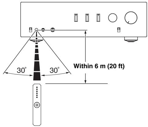
The remote control transmits a directional infrared beam. Be sure to aim the remote control directly at the remote control sensor on the front panel of this unit during operation.
③ PHONES jack
Outputs audio for private listening with headphones.
Note
When headphones are plugged in:
- Both speaker sets connected to the SPEAKERS L/R CH A and B terminals are turned off.
- No signals are output at the PRE OUT jacks, while signals are output at the REC jacks.
- You cannot select MAIN DIRECT as the input source.
- If headphones are plugged into the PHONES jack while MAIN DIRECT is selected as the input source, no audio is output at the PHONES jack. Use the headphones jack of the preamplifier connected to the MAIN IN jacks.
④ SPEAKERS
Turns on or off the speaker set connected to the SPEAKERS L/R CH A and/or B terminals on the rear panel.
- Switch to the OFF position to turn off both speaker sets.
- Switch to the A or B position to turn on the speaker set connected to the SPEAKERS L/R CH A or B terminals.
- Switch to the A+B BI-WIRING position to turn on both speaker sets.
Caution
If you use two sets (A and B), the impedance of each speaker must be 8 or higher. When only using one set of speakers (A or B), use speakers with an impedance of 4 or higher.
Front panel (right side)
YAMAHA


PHONES

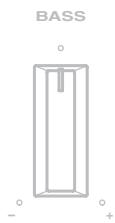
BASS

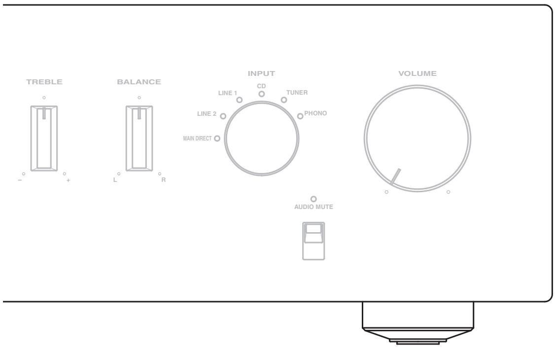
(5) BASS
Increases or decreases the low frequency response. The center position produces a flat response.
Control range: -9 dB to +9 dB
(6) TREBLE
Increases or decreases the high frequency response. The center position produces a flat response.
Control range: -9 dB to +9 dB

When both the BASS and TREBLE controls are set to the center position, audio signal bypasses the tone control circuitry.
Note
The BASS and TREBLE controls do not affect the signals input at the MAIN IN jacks (INPUT selector: MAIN DIRECT) and signals output at the REC OUT jacks.
⑦ BALANCE
Adjusts the audio output balance of the left and right speakers to compensate for sound imbalances caused by speaker locations or listening room conditions.
Note
The BALANCE control does not affect the signals input at the MAIN IN jacks (INPUT selector: MAIN DIRECT) and signals output at the REC OUT jacks.
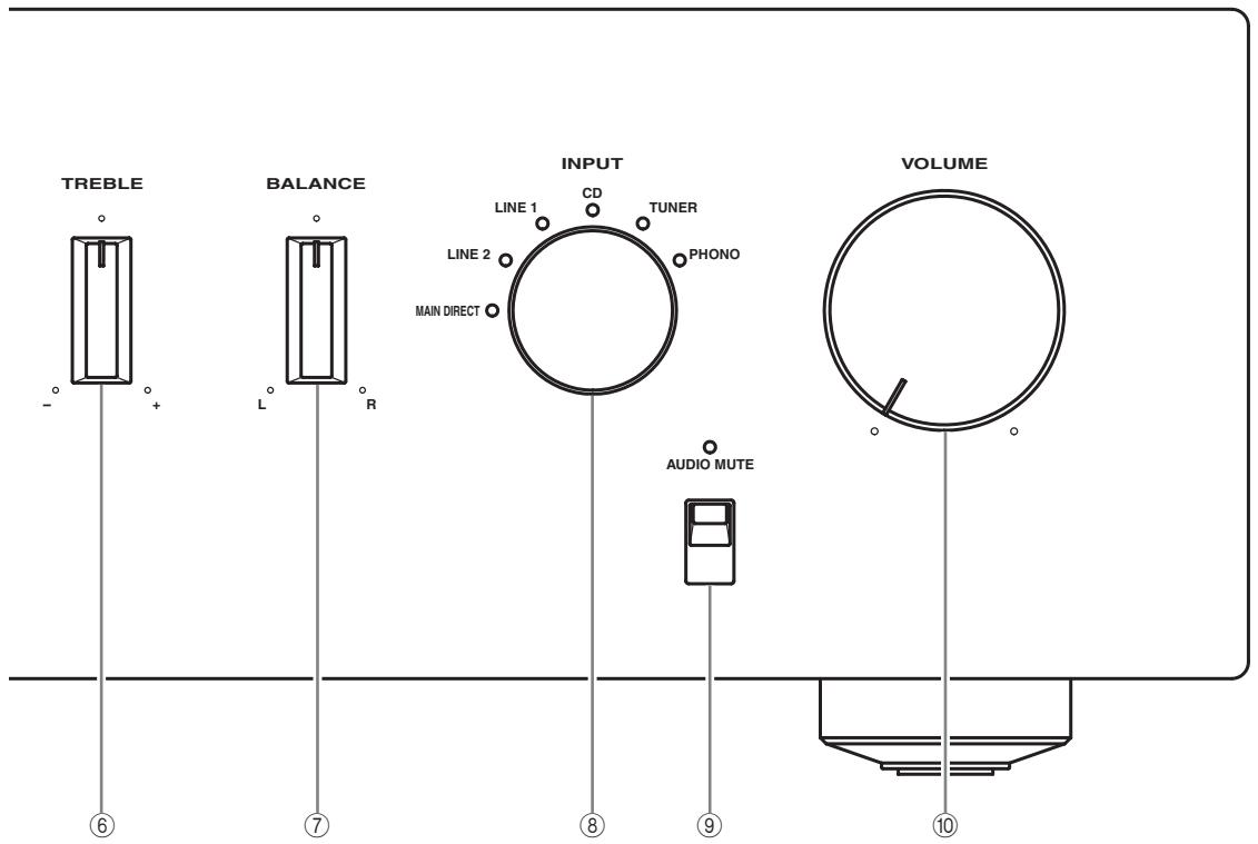
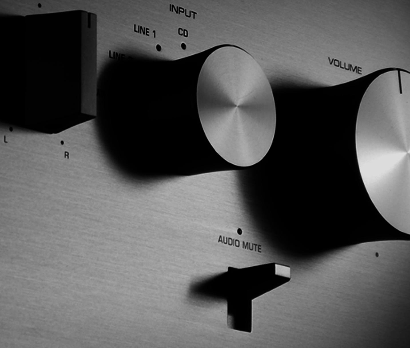
⑧ INPUT selector
Selects the input source you want to listen to.
The audio signals of the selected input source are also output at the REC jacks.

- The input source names correspond to the names of the connection jacks on the rear panel.
- Switch to the MAIN DIRECT position to select the component connected to the MAIN IN jacks. When MAIN DIRECT is selected as the input source, no signals are output at the PRE OUT, REC, and PHONES jacks.
- The input setting is retained for about 1 week after the power is turned off.
Note
The audio signals are not output at the REC jacks while LINE2 is selected as the input source.
⑨ AUDIO MUTE
Press downward to reduce the current volume level by approximately 20dB . Press again to restore the audio output to the previous volume level.

- The AUDIO MUTE indicator lights up while the mute function is on.
- You can also rotate VOLUME on the front panel or press VOL +/- on the remote control to resume the audio output.
10 VOLUME
Controls the volume level. This does not affect the REC level.
Note
The VOLUME control does not affect when you select MAIN DIRECT as the input source. Adjust the volume level using the volume control on the preamplifier connected to the MAIN IN jacks.
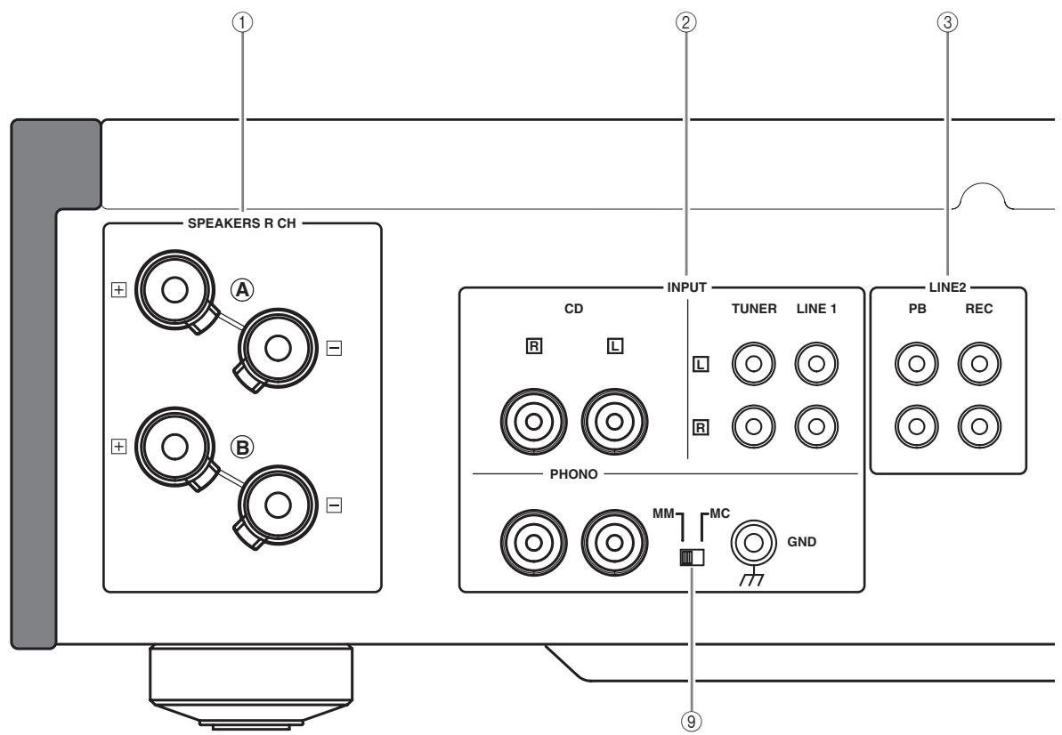
Rear panel
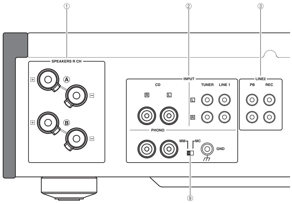
See page 14 for connection information.
① SPEAKERS L/R CH terminals
② INPUTjacks
LINE2 jacks
④ MAIN IN jacks
Note
Adjust the volume level using the volume control on the preamplifier connected to the MAIN IN jacks when you select MAIN DIRECT as the input source.
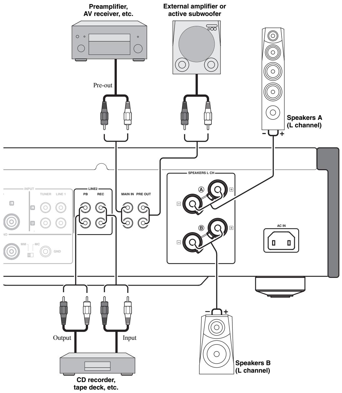
⑤ PRE OUT jacks

- When you connect audio pin plugs to the PRE OUT jacks to drive the speakers using an external amplifier, it is not necessary to use the SPEAKERS L/R CH terminals.
- The signal output at the PRE OUT jacks are affected by the BASS and TREBLE settings.
- The PRE OUT jacks output the same channel signal as the SPEAKERS L/R CH terminals.
- When you use a subwoofer, connect it to the PRE OUT jacks and speakers to the SPEAKERS L/R CH terminals.
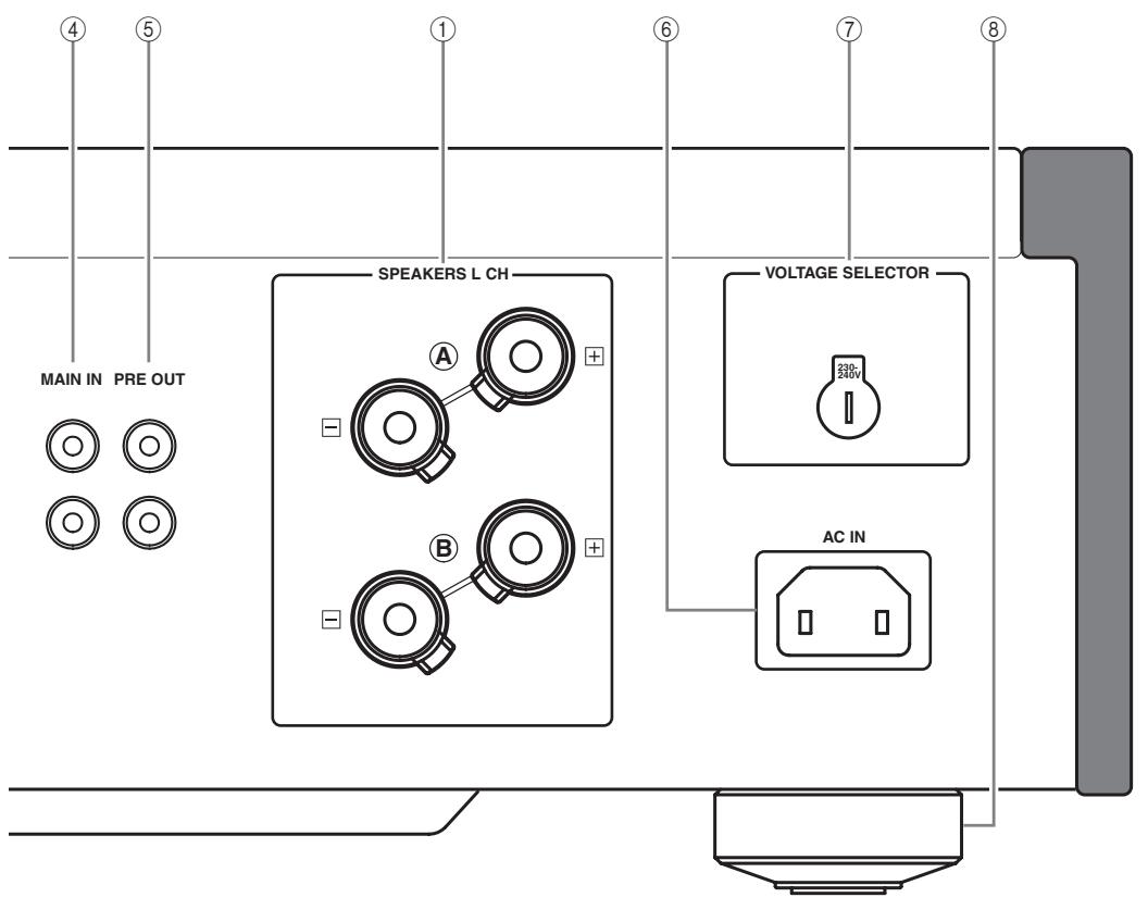
(6) AC IN
Use this inlet to plug in the supplied power cable.
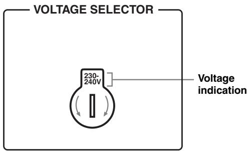
⑦ VOLTAGE SELECTOR
(Asia and General models only)
The VOLTAGE SELECTOR on the rear panel of this unit must be set for your local main voltage BEFORE plugging the power cable into the AC wall outlet. Improper setting of the VOLTAGE SELECTOR may cause damage to this unit and create a potential fire hazard.
Rotate the VOLTAGE SELECTOR clockwise or counterclockwise to the correct position using a straight slot screwdriver.
Voltages are as follows:
AC 110/120/220/230-240 V, 50/60 Hz
⑧ Foot
If this unit is unstable, you can adjust the foot height by rotating it.
(9) PHONO
Selects the type of magnetic cartridge of the turntable connected to the PHONO jacks on the rear panel.
- Set to the MM position when the connected turntable has a moving magnet (MM) cartridge.
- Set to the MC position when the connected turntable has a moving coil (MC) cartridge.
Note
When you replace the cartridge, be sure to turn off this unit.
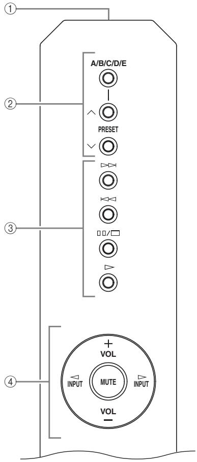
Remote control
① Infrared signal transmitter
Outputs infrared control signals.
② Yamaha tuner control buttons
Control functions of Yamaha tuner. Refer to the owner's manual of your tuner for details.
Note
Not all Yamaha tuners can be controlled by this remote control.
③ Yamaha CD player control buttons
Control various functions of Yamaha CD player. Refer to the owner's manual of your CD player for details.
中
Press / once to pause and twice to stop playback.
Note
Not all Yamaha CD players can be controlled by this remote control.
④ Amplifier control buttons
INPUT /
Selects the input source you want to listen to.
Notes
- When MAIN DIRECT is selected as the input source, no signals are output at the PRE OUT and REC jacks.
- If headphones are plugged into the PHONES jack while MAIN DIRECT is selected as the input source, no audio is output at the PHONES jack.
VOL +/-
Controls the volume level.
Note
The VOLUME control does not affect when you select MAIN DIRECT as the input source. Adjust the volume level using the volume control on the preamplifier connected to the MAIN IN jacks.
MUTE
Reduces the current volume level by approximately 20 dB. Press again to restore the audio output to the previous volume level.

You can also press VOL + / - to resume the audio output.
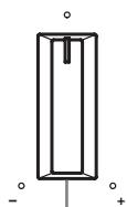
■ Installing batteries in the remote control
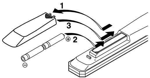
1 Press the part and slide the battery compartment cover off.
2 Insert the two supplied batteries (AA, R6, UM-3) according to the polarity markings (+ and -) on the inside of the battery compartment.
3 Slide the cover back until it snaps into place.
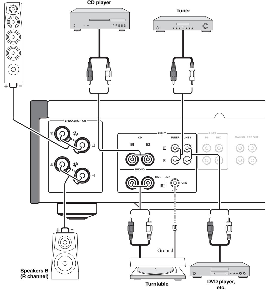
A-S1000 Connections
In this section, you will make connections between A-S1000, speakers, and source components.
Speakers A (R channel)
Caution
- If you use two sets (A and B), the impedance of each speaker must be 8 or higher. When only using one set of speakers (A or B), use speakers with an impedance of 4 or higher.
-
Do not let the bare speaker wires touch each other or do not let them touch any metal part of this unit. This could damage this unit and/or the speakers.
-
All connections must be correct: L (left) to L, R (right) to R, “+” to “+”, and “-” to “-”. If the connections are faulty, no sound will be heard from the speakers, and if the polarity of the speaker connections is incorrect, the sound will be unnatural and lack bass. Also, refer to the owner’s manual for each of your components.
- Connect your turntable to the GND terminal to reduce noise in the signal. However, you may hear less noise without the connection to the GND terminal for some turntables.
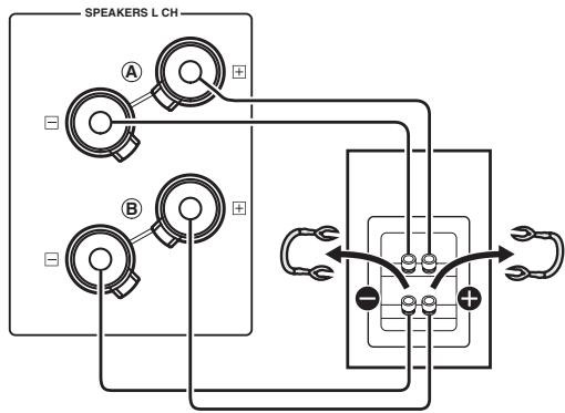
Caution
- Because the power amplifier of A-S1000 is of the floating balanced type, the following types of connections are not possible:
- Connecting with the left channel “-” terminal and the right channel “-” terminal as well as “+” terminals (Fig. 1).
- Deliberately connecting with the left/right channel “–” terminals and metal part on the rear panel of this unit, as well as accidentally touching them.
- Connecting with the left channel "−" terminal and the right channel "−" terminal inverted (cross connection, Fig. 2).
- Do not connect your active subwoofer to the SPEAKERS L/R CH terminal. Connect it to the PRE OUT jacks of this unit.
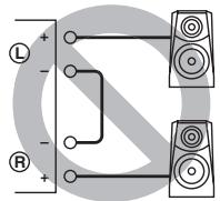
Fig. 1
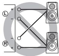
Fig. 2
Caution
If you use two sets (A and B), the impedance of each speaker must be 8 or higher. When only using one set of speakers (A or B), use speakers with an impedance of 4 or higher.
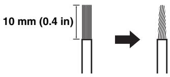
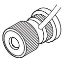
Connecting the speakers
1 Remove approximately 10mm (0.4 in) of insulation from the end of each speaker cable and twist the exposed wires of the cable together to prevent short circuits.
2 Unscrew the knob and then insert the bare wire into the hole.
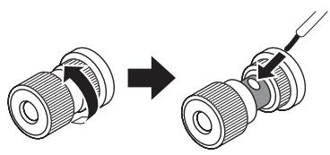
3 Tighten the knob.
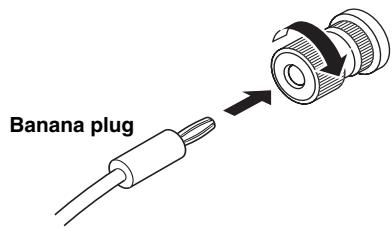
- Connecting the speakers using the banana plug (Except for Europe models)
First, tighten the knob and then insert the banana plug into the end of the corresponding terminal.
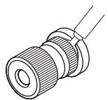
Connecting the speakers using the Y-shaped lug
1 Unscrew the knob and then sandwich the Y-shaped lug between the ring part and base.
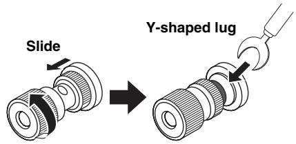
2 Tighten the knob.
Bi-wire connection
The bi-wire connection separates the woofer from the combined midrange and tweeter section. A bi-wire compatible speaker has four binding post terminals. These two sets of terminals allow the speaker to be split into two independent sections. With these connections, the mid and high frequency drivers are connected to one set of terminals and the low frequency driver to another set of terminals.
Caution
When making bi-wiring connections, use speakers with an impedance of 4 or higher.
Note
When making bi-wiring connections, remove the shorting bridges or cables on the speaker.
#
To use the bi-wire connections, switch the SPEAKERS selector to the A+B BI-WIRING position.
VOLTAGE SELECTOR
(Asia and General models only)
Caution
The VOLTAGE SELECTOR on the rear panel of this unit must be set for your local voltage BEFORE plugging the power cable into the AC wall outlet. Improper setting of the VOLTAGE SELECTOR may cause damage to this unit and create a potential fire hazard.
Rotate the VOLTAGE SELECTOR clockwise or counterclockwise to the correct position using a straight slot screwdriver.
Voltages are as follows:
AC 110/120/220/230-240 V, 50/60 Hz
Connecting the power cable
Connect the power cable into the AC IN inlet on the rear panel when all connections are complete, and then plug in the power cable to the AC wall outlet.
A-S1000 input/output table
| INPUT selector Output jacks | CD | PHONO | TUNER | LINE1 | LINE2 | MAIN DIRECT | Note |
| SPEAKERS | CD | PHONO | TUNER | LINE1 | LINE2 PB | MAIN IN | No signal is output while the SPEAKERS selector is switched to the OFF position. |
| PHONES (Headphones) | CD | PHONO | TUNER | LINE1 | LINE2 PB | - | No signal is output at the SPEAKERS terminals and PRE OUT jacks while headphones are connected to the PHONES jack. |
| PRE OUT | CD | PHONO | TUNER | LINE1 | LINE2 PB | - | |
| LINE2 REC | CD | PHONO | TUNER | LINE1 | - | - |
The shaded area indicates that the BASS, TREBLE, BALANCE, and VOLUME controls are ineffective.
A-S1000
Specifications
In this section, you will find technical specifications for A-S1000.
POWER SECTION
Minimum RMS Output Power (8 , 20 Hz to 20 kHz, 0.02% THD) .90 W + 90 W (6 , 20 Hz to 20 kHz, 0.02% THD) .105 W + 105 W (4 , 20 Hz to 20 kHz, 0.02% THD) .140 W + 140 W
- Dynamic Power (IHF) (8 / 6 / 4 / 2) 105/135/190/220 W
Maximum Output Power (1 kHz, 0.7% THD, 4 Ω) [U.K. and Europe models only] 160 W
Maximum Useful Output Power (JEITA) (1 kHz, 10% THD, 8/4 Ω) [Asia, General, China and Korea models only] 115/190 W
Dynamic Headroom 8Ω .0.67 dB
- IEC Output Power [U.K. and Europe models only] (1 kHz, 0.02% THD, 8/4 Ω). 90/145 W
Damping Factor 1 kHz,8Ω 160
Maximum Input Signal CD, etc. 2.8 V PHONO MM (1 kHz) 120 mV PHONO MC (1 kHz) 7 mV
Frequency Response CD, etc. (Flat Position, 5Hz to 100kHz ) +0/-3 dB CD, etc. (Flat Position, 20Hz to 20kHz ) +0/-0.3 dB
RIAA Equalization Deviation PHONO MM (20 Hz to 20 kHz) ± 0.5 dB PHONO MC (20 Hz to 20 kHz) ± 0.5 dB
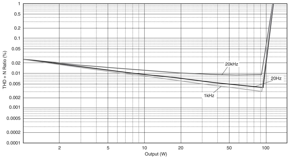
Total Harmonic Distortion CD, etc. to SP OUT (20Hz to 20kHz,90W / 8) . 0.015%
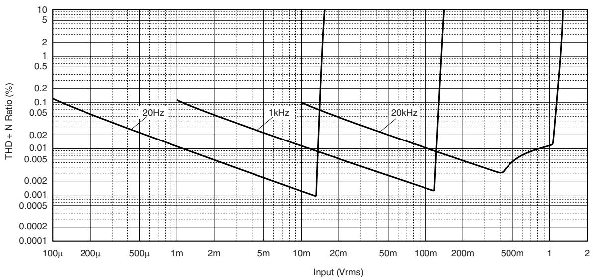
PHONO MM to REC (20 Hz to 20 kHz, 2 V) 0.005% PHONO MC to REC (20 Hz to 20 kHz, 2 V) 0.05%
- Intermodulation Distortion CD, etc. to SP OUT (Rated output, 8 Ω) 0.02%
- Signal to Noise Ratio (IHF-A Network) CD, etc. (150 mV, Input shorted) .98 dB PHONO MM (5 mV, Input shorted) .93 dB PHONO MC (500 μV, Input shorted) .85 dB
- Residual Noise (IHF-A Network) 73 μV
CONTROL SECTION
- Input Sensitivity/Input Impedance
CD, etc. 150 mV/47 kΩ
MM 2.5 mV/47 kΩ
MC 100 μV/50 Ω
MAIN IN 1 V/47 kΩ
Output Level/Output Impedance REC OUT 150 mV/1.5 kΩ PRE OUT 1 V/1.5 kΩ - Headphone Rated Output 1 kHz, 32 Ω, 0.2% THD 23 mW
- Channel Separation CD, etc. (5.1 kΩ Terminated, 1 kHz/10 kHz) 74/54 dB PHONO MM (Input shorted, 1 kHz/10 kHz, Vol.:-30 dB) 90/77 dB PHONO MC (Input shorted, 1 kHz/10 kHz, Vol.:-30 dB) 66/65 dB
- Tone Control Characteristics
BASS
Boost/Cut (50 Hz) 350 Hz
Turnover Frequency
TREBLE
Boost/Cut (20 kHz) 3.5 kHz
Audio muting. 20 dB (approx.)
GENERAL
- Power Supply
[U.S.A. and Canada models] AC 120 V, 60 Hz
[Asia model] AC 220/230-240 V, 50/60 Hz
[General model] AC 110/120/220/230-240 V, 50/60 Hz
[China model] AC 220 V, 50 Hz
[Korea model] AC 220 V, 60 Hz
[Australia model] AC 240 V, 50 Hz
[U.K. and Europe models] AC 230 V, 50 Hz
Power consumption 350 W - Idling power consumption. 80 W
- Off-state power consumption 0 W
- Dimensions (W x H x D) 435 x 137 x 465 mm (17-1/8" x 5-3/8" x 18-5/16")
Weight 22 kg (48 lbs. 8 oz.) - Specifications are subject to change without notice.

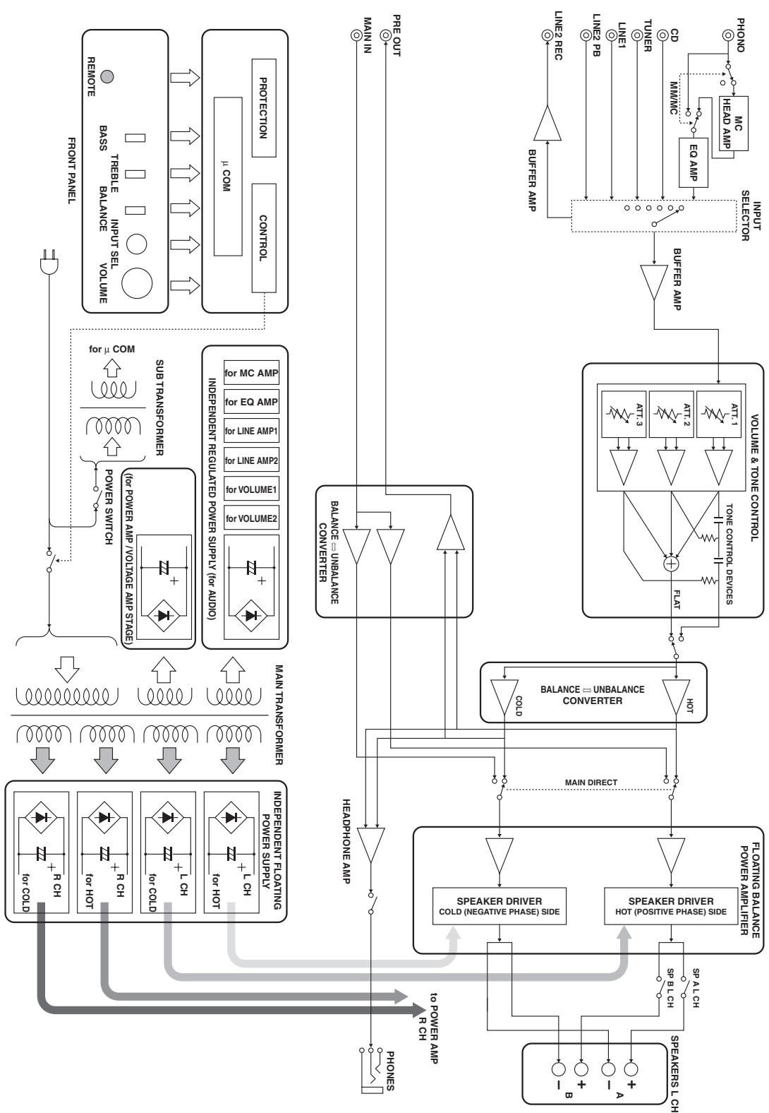
■ Block diagram
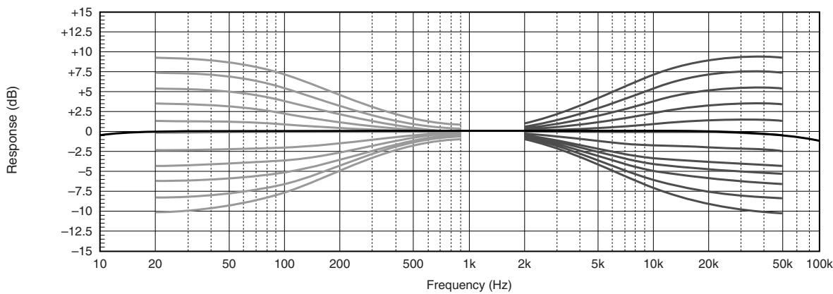
■ Tone control characteristics
Total harmonic distortion
Total harmonic distortion (PHONO)
Refer to the chart below if this unit does not function properly. If the problem you are experiencing is not listed below or if the instructions below do not help, turn off this unit, disconnect the power cable, and contact the nearest authorized Yamaha dealer or service center.
| Problem | Cause | Remedy | See page |
| This unit fails to turn on. | The power cable is not connected to the AC IN inlet on the rear panel or not plugged in the AC wall outlet. | Connect the power cable firmly. | 17 |
| The protection circuitry has been activated because of a short circuit, etc. | Check that the speaker wires are not touching each other or shorting out against the rear panel of this unit, and then turn the power of this unit back on. | 14 | |
| This unit has been exposed to a strong external electric shock (such as lightning or strong static electricity). | Turn off this unit, disconnect the power cable, plug it back in after 30 seconds, and then use it normally. | — | |
| The POWER indicator on the front panel flashes. | The protection circuitry has been activated because of a short circuit, etc. | Check that the speaker wires are not touching each other or shorting out against the rear panel of this unit, and then turn the power of this unit back on. | 14 |
| There is a problem with the internal circuitries of this unit. | Disconnect the power cable and contact the nearest authorized Yamaha dealer or service center. | — | |
| The INPUT indicator on the front panel flashes and the volume is turned down when you turn on this unit. | The protection circuitry has been activated because of a short circuit, etc. | Check that the speaker wires are not touching each other or shorting out against the rear panel of this unit, and then turn the power of this unit back on. | 14 |
| No sound. | Incorrect input or output cable connections. | Connect the cables properly. If the problem persists, the cables may be defective. | 14 |
| No appropriate input source has been selected. | Select an appropriate input source with the INPUT selector on the front panel (or one of the input selector buttons on the remote control). | 9, 12 | |
| The SPEAKERS switch is not set properly. | Switch the SPEAKERS switch to the appropriate position. | 7 | |
| Speaker connections are not secure. | Secure the connections. | 14 | |
| The sound suddenly goes off. | The protection circuitry has been activated because of a short circuit, etc. | Check that the speaker wires are not touching each other or shorting out against the rear panel of this unit, and then turn the power of this unit back on. | 14 |
| Only the speaker on one side can be heard. | Incorrect cable connections. | Connect the cables properly. If the problem persists, the cables may be defective. | 14 |
| Incorrect setting for the BALANCE control. | Set the BALANCE control to the appropriate position. | 8 | |
| There is a lack of bass and no ambience. | The + and – wires are connected in reverse at the amplifier or the speakers. | Connect the speaker wires to the correct + and – phase. | 14 |
| A “humming” sound is heard. | Incorrect cable connections. | Connect the audio cable plugs firmly. If the problem persists, the cables may be defective. | 14 |
| No connection from the turntable to the GND terminal. | Connect the turntable to the GND terminal of this unit. | 14 | |
| The volume level is low while playing a record. | The turntable is connected to the jacks other than the PHONO jacks. | Connect the turntable to the PHONO jacks. | 11 |
| Incorrect setting for the PHONO switch on the rear panel. | Switch the PHONO switch to the MM or MC position according to the type of magnetic cartridge of the turntable. | 11 | |
| The sound is degraded when listening with the headphones connected to the CD player connected to this unit. | The power of this unit is turned off. | Turn on the power of this unit. | 6 |
| The remote control does not work or function properly. | Wrong distance or angle. | The remote control functions within a maximum range of 6 m (20 ft) and no more than 30 degrees off-axis from the front panel. | 6 |
| Direct sunlight or lighting (from an inverter type of fluorescent lamp, etc.) is striking the remote control sensor of this unit. | Reposition this unit. | — | |
| The batteries are weak. | Replace all batteries. | 12 |
Taking care of this unit
When you wipe this unit, do not use chemical solvents (ex. alcohol or thinner, etc.); this might damage the finish. Use a clean, dry cloth. For heavy dirt, dampen a soft cloth in detergent diluted with the water, wring it out, and then clean this unit up with the cloth.
The screws on the side panels may loosen as wood expands and contracts. In this case, tighten the screws.
① Bornes SPEAKERS L/R CH
(2) Prises INPUT
(3) Prises LINE2
(4) Prises MAIN IN
Remarque
A-S1000 Raccordements
Collegamento bi-wire
Altavoz monitor NS-1000M
Reprodctor CD GT-CD1
Reprodctor de energia superior con estruktura separada integrazione
(1 kHz, THD de 10%, 8/4 Ω)
[Modelos de Asia, General, China y Corea solamente] 115/190 W
- Techo dinámico
8Ω 0,67dB
- Potencia de salute IEC [Modelos del R.U. y Europa solamente]
(1 kHz, THD de 0.02%, 8/4 Ω) 90/145 W
- Factor de amortiguation
1 kHz, 8Ω 160
- Senal de entrada Tmaxima
CD,etc. 2,8V
PHONO MM (1 kHz) 120 mV
PHONO MC (1 kHz) 7 mV
PHONOMM a REC (20 Hz a 20 kHz, 2 V) 0.005%
PHONO MC a REC (20 Hz a 20 kHz, 2 V) 0.05%
BcTpoehbIycnJIHTeJbA-1
IIpOurpbIbArteJIb PX-1
IepBbI IIpoHrPbIBaTeJIb YamaHa c JInHeHbIM TpeKHHROM
YchJIHTeJIb MOUHOCTH B-6
PerjIaTOP VOLUME He cpa6aTbIbAeT Iprn BbIbOpe MAIN DIRECT B KaueCTBe HcTOUHNa IIpHeMa. HAcTpAnBaIte yPoBeHb rPOMKoCTH C IIOMOIbH o PerjIaTOPa rPOMKoCTH Ha IIpeDyCNJIInTeJI, IIOKNJIOUeHHOM K IrHe3JaM MAIN IN.
3aDnnaNaHeIb
中
CMOTpIte ctp. 14 JJIa HnΦopMaIIH NIOIIOKJIIOUeHHIO.
① TepmHaJIbI SPEAKERS L/R CH
② THe3da INPUT
③ THe3da LINE2
④ THe3da MAIN IN
PpmeaHne
Пи Вьборе MAIN DIRECT в Каустve Источнka IIрима, Hab相对较БупЕвг ромКоCTN C I IOMOIьО peRyJIЯТopa ромКоCTN Ha IIpeДуСИЛТeJIe, IIOДКЛЮЧEHOM K rHe3ДaM MAIN IN.
(5) THe3da PRE OUT
-Пи IOДКЛIOчЕнгуАДИОПТeпCEJIbHOH BЛКИK K rHe3ДaM PRE OUTДЯ упраВЛeнгу KOJOHKaMH OT BHeIHIero yCHIINTEJIA, HET HeO6XoDmOCtN B HcIOJIb3OBAHnI TepMHHaJIOB SPEAKERS L/R CH.
- CnHraJI, BbIOBDAIINsCHa rHe3Ja PRE OUT, IIOBBePRAeTcB JInHNNo HacTpoeK BASS n TREBLE.
- ΕHe3Дa PRE OUT bIbOJrT cHrHaJI OДИнAkoBOrO KaHaJIa cCOOTBeTcTBYIOUIMN TePmHaJaAM SPEAKERS L/R CH.
-Пин ИсIOЛьЗОВаHHИ ca6Byфepa,ПОДКЛЮчHTe erO K rHe3Дam PRE OUT,a KOJIIOHKn -K TepMHHaJAm SPEAKERS L/R CH.

(6) AC IN
IaHHbI BxOJ hCIOJIb3yeTc JJI IOKJIIOUeHnIIOCTABJIaEMORO CNIOBORO Ka6JIa.
⑦ VOLTAGE SELECTOR
(Tolbko MoeJIb dIa A3nn n o6uae MoeJIb)
CeJIeKTop VOLTAGE SELECTOR Ha 3aJHeiHaHeJIi DaHHoro aIIIapata DoJIxKeH 6bITb yCTaHOBJeH Ha MeCTHoe HauPjaXeHne IIOIOKJIIOUeHnCNIIOBOrKa6eJIa K pO3eTke IIepMeHHoro TOka. HeIpaBnJIbHaay UcTaHOBka VOLTAGE SELECTOR MoXeT IOBpeINb TdaHHbI aIIIapat N co3JaTb pNCK BO3MOxHOrO IIOXapa.
Поворачва ВOLTAGE SELECTOR ИQuacoBoH HIN IpoTHB YacBOH CTpeJIKN C IOMOIIbIO OTBepTKN, yCTaHOBHTe eRo Ha COOTBeTCTByIOIIyIO IO3NIIIIO. ИмeIoTc CJeIyIOIIne NaIprJxKeHH:
110/120/220/230-240 B IIepeMeHHoro TOKa, 50/60 I
⑧ Hoxkα
EcHn DaHHbI aIIIpaT HeYcTOHNB, MoXHO TpeRyJInPOBaTb BBICOTy HOKKn, IIOBopaHBAa ee.
(9) PHONO
Bb6op TIIa MaHHTHOI YoOBKn 3ByKoCHMaTeJI
IIPOHrpBtAEJI,IOIKJIOUeHHORO K rHe3dAm
PHONO Ha 3aJIHe IaHeJI.
- EcJIN IIOKJIIOUeHHbI IPOHrpBbATEJB o6OpyIOBaH ROJIOBKO 3ByKOCHMaTEJI C IOIBNXHBIM MaHHTOM (MM), yCTaHOBtE Ha IIO3NIIIO MM.
- EcJIN IIOKJIIOUeHHbI IIPOINrPBiBaTeJIb O6OpyIOBaH ROJIOBKO 3ByKOCHNMaTeJIa C IOINBnKHO KAtyIIKOI (MC), yCTaHOBHTe Ha IIO3NIIIO MC.
PpmeuHne
Pn3aMeHe roJIOBKN 3ByKOCHMaTeJIa, O6BaTeJIbHO OTKJIIOHTe daHHbI aIIIapaT.
IynbT dy
① IpepaTnK nHpaKpaCpHOro cnHaJa BbIOI nHpaPaKpaChbIX cnHaJIob yPiabJIeHHa
② KhoNkynpaBJIeHnTIOhepOMYama
YnpaBJIeHne yHKIyMaMn TIOhepaYama. IOpno6Hee,
cmOTpInTe HnCTpyKUHO IO 3KcIIyAtauIN K TIOhepy.
PpmeaHne
Данньй пьлт Ду не может управлиь BCМн ТIOHEpaM YamaHa.
③ KhoNk ynpabJIeHn CD-npOngpIbATEJem YamaHa YIpaJIeHHe pa3JIuHbIMn fYHKIIJMaMn CD- IIpoONpRpbIbATEJr YamaHa. IIOJPO6Hee, cMOrPtHe HNCTpyKIIHIO IO kCJIyataHn K CD-npOngpIBaTeJIHO.
中
HaxMMTe / OINH pa3 IIaIy3bI, INBa pa3a IIJIA octaHOBKn BOCIIpOIN3BeJeHH.
PpmeaHne
Ta6nica BxoIOB/BbIXoIOB A-S1000
© 2008 YAMAHA CORPORATION All rights reserved.
Stereo Amplifier
Caution: Read this before operating your unit.
1 To assure the finest performance, please read this manual carefully. Keep it in a safe place for future reference.
2 Install this sound system in a well ventilated, cool, dry, clean place - away from direct sunlight, heat sources, vibration, dust, moisture, and/or cold. Allow ventilation space of at least 30~cm on the top, 20~cm on the left and right, and 20~cm on the back of this unit.
3 Locate this unit away from other electrical appliances, motors, or transformers to avoid humming sounds.
4 Do not expose this unit to sudden temperature changes from cold to hot, and do not locate this unit in an environment with high humidity (i.e. a room with a humidifier) to prevent condensation inside this unit, which may cause an electrical shock, fire, damage to this unit, and/or personal injury.
5 Avoid installing this unit where foreign objects may fall onto this unit and/or this unit may be exposed to liquid dripping or splashing. On the top of this unit, do not place:
- Other components, as they may cause damage and/or discoloration on the surface of this unit.
- Burning objects (i.e. candles), as they may cause fire, damage to this unit, and/or personal injury.
- Containers with liquid in them, as they may fall and liquid may cause electrical shock to the user and/or damage to this unit.
6 Do not cover this unit with a newspaper, tablecloth, curtain, etc. in order not to obstruct heat radiation. If the temperature inside this unit rises, it may cause fire, damage to this unit, and/or personal injury.
7 Do not plug in this unit to a wall outlet until all connections are complete.
8 Do not operate this unit upside-down. It may overheat, possibly causing damage.
9 Do not use force on switches, knobs and/or cords.
10 When disconnecting the power cable from the wall outlet, grasp the plug; do not pull the cable.
11 Do not clean this unit with chemical solvents; this might damage the finish.
12 Only voltage specified on this unit must be used. Using this unit with a higher voltage than specified is dangerous and may cause fire, damage to this unit, and/or personal injury. Yamaha will not be held responsible for any damage resulting from use of this unit with a voltage other than specified.
13 To prevent damage by lightning, keep the power cord disconnected from a wall outlet or the unit during a lightning storm.
14 Do not attempt to modify or fix this unit. Contact qualified Yamaha service personnel when any service is needed. The cabinet should never be opened for any reasons.
15 When not planning to use this unit for long periods of time (i.e. vacation), disconnect the AC power plug from the wall outlet.
16 Install this unit near the AC outlet and where the AC power plug can be reached easily.
17 Be sure to read the "Troubleshooting" section in the owner's manual on common operating errors before concluding that this unit is faulty.
18 Before moving this unit, press POWER downward to turn off this unit and then disconnect the AC power plug from the AC wall outlet.
19 VOLTAGE SELECTOR (Asia and General models only) The VOLTAGE SELECTOR on the rear panel of this unit must be set for your local main voltage BEFORE plugging into the AC wall outlet. Voltages are: AC 110/120/220/230-240 V, 50/60 Hz
20 The batteries shall not be exposed to excessive heat such as sunshine, fire or like.
21 Excessive sound pressure from earphones and headphones can cause hearing loss.
As long as this unit is connected to the AC wall outlet, it is not disconnected from the AC power source even if you turn off this unit by POWER.
WARNING
TO REDUCE THE RISK OF FIRE OR ELECTRIC SHOCK, DO NOT EXPOSE THIS UNIT TO RAIN OR MOISTURE.

This symbol mark is according to the EU directive 2002/96/EC.
This symbol mark means that electrical and electronic equipment, at their end-of-life, should be disposed of separately from your household waste.
Please act according to your local rules and do not dispose of your old products with your normal household waste.
Notes on batteries
- Change all of the batteries if you notice that the operation range of the remote control decreases.
- Use AA, R6, UM-3 batteries.
- Make sure that the polarities are correct. See the illustration inside the battery compartment.
- Remove the batteries if the remote control is not used for an extended period of time.
- Do not use old batteries together with new ones.
- Do not use different types of batteries (such as alkaline and manganese batteries) together. Read the packaging carefully as these different types of batteries may have the same shape and color.
- If the batteries have leaked, dispose of them immediately. Avoid touching the leaked material or letting it come into contact with clothing, etc. Clean the battery compartment thoroughly before installing new batteries.
- Do not throw away batteries with general house waste; dispose of them correctly in accordance with your local regulations.
Handling the remote control
- The area between the remote control and this unit must be clear of large obstacles.
- Do not spill water or other liquids on the remote control.
- Do not drop the remote control.
- Do not leave or store the remote control in the following types of conditions:
places of high humidity, such as near a bath
places of high temperature, such as near a heater or a stove
places of extremely low temperatures
-dusty places
- Do not expose the remote control sensor to strong lighting, in particular, an inverter type fluorescent lamp; otherwise, the remote control may not work properly. If necessary, position this unit away from direct lighting.
Limited Guarantee for European Economic Area (EEA) and Switzerland
Thank you for having chosen a Yamaha product. In the unlikely event that your Yamaha product needs guarantee service, please contact the dealer from whom it was purchased. If you experience any difficulty, please contact Yamaha representative office in your country. You can find full details on our website (http://www.yamaha-hifi.com/ or http://www.yamaha-uk.com/ for U.K. resident).
The product is guaranteed to be free from defects in workmanship or materials for a period of two years from the date of the original purchase. Yamaha undertakes, subject to the conditions listed below, to have the faulty product or any part(s) repaired, or replaced at Yamaha's discretion, without any charge for parts or labour. Yamaha reserves the right to replace a product with that of a similar kind and/or value and condition, where a model has been discontinued or is considered uneconomic to repair.
Conditions
- The original invoice or sales receipt (showing date of purchase, product code and dealer's name) MUST accompany the defective product, along with a statement detailing the fault. In the absence of this clear proof of purchase, Yamaha reserves the right to refuse to provide free of charge service and the product may be returned at the customer's expense.
- The product MUST have been purchased from an AUTHORISED Yamaha dealer within the European Economic Area (EEA) or Switzerland.
- The product must not have been the subject of any modifications or alterations, unless authorised in writing by Yamaha.
- The following are excluded from this guarantee:
a. Periodic maintenance and repair or replacement of parts due to normal wear and tear.
b. Damage resulting from:
(1) Repairs performed by the customer himself or by an unauthorised third party.
(2) Inadequate packaging or mishandling, when the product is in transit from the customer. Please note that it is the customer's responsibility to ensure the product is adequately packaged when returning the product for repair.
(3) Misuse, including but not limited to (a) failure to use the product for its normal purpose or in accordance with Yamaha's instructions on the proper use, maintenance and storage, and (b) installation or use of the product in a manner inconsistent with the technical or safety standards in force in the country where it is used.
(4) Accidents, lightning, water, fire, improper ventilation, battery leakage or any cause beyond Yamaha's control.
(5) Defects of the system into which this product is incorporated and/or incompatibility with third party products.
(6) Use of a product imported into the EEA and/or Switzerland, not by Yamaha, where that product does not conform to the technical or safety standards of the country of use and/or to the standard specification of a product sold by Yamaha in the EEA and/or Switzerland.
(7) Non AV (Audio Visual) related products. (Products subject to "Yamaha AV Guarantee Statement" are defined in our website at http://www.yamaha-hifi.com/ or http://www.yamaha-uk.com/ for U.K. resident.)
- Where the guarantee differs between the country of purchase and the country of use of the product, the guarantee of the country of use shall apply.
- Please backup any custom settings or data, as Yamaha may not be held responsible for any alteration or loss to such settings or data.
- This guarantee does not affect the consumer's statutory rights under applicable national laws in force or the consumer's rights against the dealer arising from their sales/purchase contract.
-MecTaX C IIOBbIIIEHHO BJIaXHOCTbIO, HAIpHMeP, BO3JIe BaHHoI
-B MeCTax C IIOBbIIeHHoT TeMIIepaTypoI, HAIpHMeP, BO3JIe O6OrpeBaTeJIa HJIN IIJNTbI
-B MeCTax C IIpeJeJIbHO Hn3KHMN TeMIIepaTypaMI -B 3aIIbJIeHHbIX MeCTax
He IIOBepraIte ceHcOp IY IOIIaHaHHO cHJIbHorO cBeta, B OCO6eHHoCTH,OT φJyOpEcUeHTHOJIaMIbI INHBePTePHORO TINIIa; B IPOITHBOM cIJyae, IYJIbT Y MOKeT pa6OtaTB HeCOOTBEcTByIOIH M o6pa3OM. IIpH HeOxOIMOCTH, IpeEiBHHbTe JaHHbI aIIIapAT IOJaJIbIIe OT IIPMOrO IOIIaHaHH CBeTa.

YAMAHA
© 2008 YAMAHA CORPORATION All rights reserved.