
IPA8200 - Audio Amplifier YAMAHA - Free user manual and instructions
Find the device manual for free IPA8200 YAMAHA in PDF.
User questions about IPA8200 YAMAHA
0 question about this device. Answer the ones you know or ask your own.
Ask a new question about this device
Download the instructions for your Audio Amplifier in PDF format for free! Find your manual IPA8200 - YAMAHA and take your electronic device back in hand. On this page are published all the documents necessary for the use of your device. IPA8200 by YAMAHA.
USER MANUAL IPA8200 YAMAHA
The above warning is located on the top of the unit.
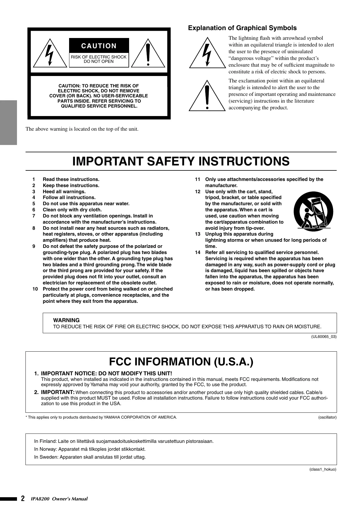
Explanation of Graphical Symbols
The lightning flash with arrowhead symbol within an equilateral triangle is intended to alert the user to the presence of uninsulated “dangerous voltage” within the product’s enclosure that may be of sufficient magnitude to constitute a risk of electric shock to persons.

The exclamation point within an equilateral triangle is intended to alert the user to the presence of important operating and maintenance (servicing) instructions in the literature accompanying the product.
IMPORTANT SAFETY INSTRUCTIONS
1 Read these instructions.
2 Keep these instructions.
3 Heed all warnings.
4 Follow all instructions.
5 Do not use this apparatus near water.
6 Clean only with dry cloth.
7 Do not block any ventilation openings. Install in accordance with the manufacturer's instructions.
8 Do not install near any heat sources such as radiators, heat registers, stoves, or other apparatus (including amplifiers) that produce heat.
9 Do not defeat the safety purpose of the polarized or grounding-type plug. A polarized plug has two blades with one wider than the other. A grounding type plug has two blades and a third grounding prong. The wide blade or the third prong are provided for your safety. If the provided plug does not fit into your outlet, consult an electrician for replacement of the obsolete outlet.
10 Protect the power cord from being walked on or pinched particularly at plugs, convenience receptacles, and the point where they exit from the apparatus.
11 Only use attachments/accessories specified by the manufacturer.
12 Use only with the cart, stand, tripod, bracket, or table specified by the manufacturer, or sold with the apparatus. When a cart is used, use caution when moving the cart/apparatus combination to avoid injury from tip-over.
13 Unplug this apparatus during lightning storms or when unused for long periods of time.
14 Refer all servicing to qualified service personnel. Servicing is required when the apparatus has been damaged in any way, such as power-supply cord or plug is damaged, liquid has been spilled or objects have fallen into the apparatus, the apparatus has been exposed to rain or moisture, does not operate normally, or has been dropped.

WARNING
TO REDUCE THE RISK OF FIRE OR ELECTRIC SHOCK, DO NOT EXPOSE THIS APPARATUS TO RAIN OR MOISTURE.
(UL60065_03)
FCC INFORMATION (U.S.A.)
- IMPORTANT NOTICE: DO NOT MODIFY THIS UNIT!
This product, when installed as indicated in the instructions contained in this manual, meets FCC requirements. Modifications not expressly approved by Yamaha may void your authority, granted by the FCC, to use the product. - IMPORTANT: When connecting this product to accessories and/or another product use only high quality shielded cables. Cable/s supplied with this product MUST be used. Follow all installation instructions. Failure to follow instructions could void your FCC authorization to use this product in the USA.
(oscillator)
* Please keep this manual in a safe place for future reference.

WARNING
Always follow the basic precautions listed below to avoid the possibility of serious injury or even death from electrical shock, short-circuiting, damages, fire or other hazards. These precautions include, but are not limited to, the following:
Power supply/Power cord
- Only use the voltage specified as correct for the device. The required voltage is printed on the name plate of the device.
- Use only the included power cord.
If you intend to use the device in an area other than in the one you purchased, the included power cord may not be compatible. Please check with your Yamaha dealer. - Do not place the power cord near heat sources such as heaters or radiators, and do not excessively bend or otherwise damage the cord, place heavy objects on it, or place it in a position where anyone could walk on, trip over, or roll anything over it.
- Be sure to connect to an appropriate outlet with a protective grounding connection. Improper grounding can result in electrical shock.
Do not open
- Do not open the device or attempt to disassemble the internal parts or modify them in any way. The device contains no user-serviceable parts. If it should appear to be malfunctioning, discontinue use immediately and have it inspected by qualified Yamaha service personnel.
Water warning
- Do not expose the device to rain, use it near water or in damp or wet conditions, or place containers on it containing liquids which might spill into any openings. If any liquid such as water seeps into the device, turn off the power immediately and unplug the power cord from the AC outlet. Then have the device inspected by qualified Yamaha service personnel.
- Never insert or remove an electric plug with wet hands.
If you notice any abnormality
- If the power cord or plug becomes frayed or damaged, or if there is a sudden loss of sound during use of the device, or if any unusual smells or smoke should appear to be caused by it, immediately turn off the power switch, disconnect the electric plug from the outlet, and have the device inspected by qualified Yamaha service personnel.
- If this device should be dropped or damaged, immediately turn off the power switch, disconnect the electric plug from the outlet, and have the device inspected by qualified Yamaha service personnel.

CAUTION
Always follow the basic precautions listed below to avoid the possibility of physical injury to you or others, or damage to the device or other property. These precautions include, but are not limited to, the following:
Power supply/Power cord
- Remove the electric plug from the outlet when the device is not to be used for extended periods of time, or during electrical storms.
- When removing the electric plug from the device or an outlet, always hold the plug itself and not the cord. Pulling by the cord can damage it.
Location
- Before moving the device, remove all connected cables.
- When setting up the device, make sure that the AC outlet you are using is easily accessible. If some trouble or malfunction occurs, immediately turn off the power switch and disconnect the plug from the outlet. Even when the power switch is turned off, electricity is still flowing to the product at the minimum level. When you are not using the product for a long time, make sure to unplug the power cord from the wall AC outlet.
-
If the device is mounted in an EIA standard rack, carefully read the section "Precautions when rack-mounting the unit" on page 5. Inadequate ventilation can result in overheating, possibly causing damage to the device(s), malfunction, or even fire.
-
Do not use the device in a confined, poorly-ventilated location. Make sure that there is adequate space between the device and surrounding walls or other devices: at least 5cm at the sides, 10cm behind and 10cm above. Inadequate ventilation can result in overheating, possibly causing damage to the device(s), or even fire.
- Do not expose the device to excessive dust or vibrations, or extreme cold or heat (such as in direct sunlight, near a heater, or in a car during the day) to prevent the possibility of panel disfiguration or damage to the internal components.
- Do not place the device in an unstable position where it might accidentally fall over.
- Do not block the vents. This device has ventilation holes at the front and rear to prevent the internal temperature from becoming too high. In particular, do not place the device on its side or upside down. Inadequate ventilation can result in overheating, possibly causing damage to the device(s), or even fire.
- Do not use the device in the vicinity of a TV, radio, stereo equipment, mobile phone, or other electric devices. Doing so may result in noise, both in the device itself and in the TV or radio next to it.
- Do not place the device in a location where it may come into contact with corrosive gases or salt air. Doing so may result in malfunction.
Connections
- Before connecting the device to other devices, turn off the power for all devices. Before turning the power on or off for all devices, set all volume levels to minimum.
- Turn off the power before connecting speakers, and use only the speaker cables for connecting speakers to the speaker jacks. Failure to do so can result in fire or electrical shock.
Handling caution
- When turning on the AC power in your audio system, always turn on the device LAST, to avoid speaker damage. When turning the power off, the device should be turned off FIRST for the same reason.
- Condensation can occur in the device due to rapid, drastic changes in ambient temperature – when the device is moved from one location to another, or airconditioning is turned on or off, for example. Using the device while condensation is present can cause damage. If there is reason to believe that
condensation might have occurred, leave the device for several hours without turning on the power until the condensation has completely dried out.
- Do not insert your fingers or hands in any gaps or openings on the device (vents).
- Avoid inserting or dropping foreign objects (paper, plastic, metal, etc.) into any gaps or openings on the device (vents) If this happens, turn off the power immediately and unplug the power cord from the AC outlet. Then have the device inspected by qualified Yamaha service personnel.
- Do not use speakers for a long period of time at a high or uncomfortable volume level, since this can cause permanent hearing loss. If you experience any hearing loss or ringing in the ears, consult a physician.
- Do not rest your weight on the device or place heavy objects on it, and avoid use excessive force on the buttons, switches or connectors.
- Do not use this device for any purpose other than driving loudspeakers.
Yamaha cannot be held responsible for damage caused by improper use or modifications to the device, or data that is lost or destroyed.
Always turn the power off when the device is not in use.
The performance of components with moving contacts, such as switches, volume controls, and connectors, deteriorates over time. Consult qualified Yamaha service personnel about replacing defective components.
European models
Purchaser/User Information specified in EN55103-1 and EN55103-2.
Inrush Current: 26A
Conforms to Environments: E1, E2, E3 and E4
* Specifications and descriptions in this owner's manual are for information purposes only. Yamaha Corp. reserves the right to change or modify products or specifications at any time without prior notice. Since specifications, equipment or options may not be the same in every locale, please check with your Yamaha dealer.
IMPORTANT NOTICE FOR THE UNITED KINGDOM
Connecting the Plug and Cord
WARNING: THIS APPARATUS MUST BE EARTHED
IMPORTANT. The wires in this mains lead are coloured in accordance with the following code:
| GREEN-AND-YELLOW | : EARTH |
| BLUE | : NEUTRAL |
| BROWN | : LIVE |
As the colours of the wires in the mains lead of this apparatus may not correspond with the coloured markings identifying the terminals in your plug proceed as follows:
The wire which is coloured GREEN-and-YELLOW must be connected to the terminal in the plug which is marked by the letter E or by the safety earth symbol ⏻ or colored GREEN or GREEN-and-YELLOW.
The wire which is coloured BLUE must be connected to the terminal which is marked with the letter N or coloured BLACK.
The wire which is coloured BROWN must be connected to the terminal which is marked with the letter L or coloured RED.
- This applies only to products distributed by Yamaha Music U.K. Ltd.
(3 wires)
Introduction
Thank you for purchasing the Yamaha IPA8200 power amplifier.
In order to take full advantage of the IPA8200's functionality and to ensure trouble-free operation, please read this owner's manual carefully before use.
After you have read the manual, keep it in a safe place for reference when needed.
Features
■ Space-saving high-efficiency multi-channel 200W@4Ω x 8 power amplifier
■ Switchable between STEREO/PARALLEL/BRIDGE modes as needed for your application
■ Euroblock input jacks and barrier strip output jacks for easy installation
■ High-pass filter with switchable cutoff frequency (20 Hz / 55 Hz)
■ Input sensitivity / gain select switch switchable between three positions (+4 dBu, 26 dB, 32 dB)
Precautions when rack-mounting the unit
Operation of this device is guaranteed for an environmental temperature range of 0 – 40°C. If you are mounting only this device in an EIA standard rack, you may mount multiple units without leaving a space between them. If you are mounting this device along with other types of device in an EIA standard rack, the ambient temperature inside the rack may rise due to heat produced from the other devices, preventing this device from performing as designed. To ensure that heat does not build up inside this device, you must observe the following conditions when mounting it in a rack.
- If you mount this device in a rack together with heat-generating devices such as power amps made by other companies, you must leave 1U or more space between this device and other devices. You should also install a ventilation panel in this space or leave it open to ensure adequate ventilation.
- Leave the back of the rack open, and allow 10 cm or more distance between the rack and the wall or ceiling to ensure adequate ventilation. If you are unable to leave the back of the rack open, you must install a commercially available fan kit or other forced air circulating system to the rack. If you have installed a fan kit, there may be cases in which closing the back of the rack will provide better cooling. For details, refer to the instructions that came with the rack system or fan kit.
Contents
Introduction......5
Features 5
Precautions when rack-mounting the unit ....5
Controls and Functions ....7
Front Panel....7
Rear Panel....8
Mode settings 9
STEREO mode....9
PARALLEL mode 9
BRIDGE mode....9
Connections....10
Input jack connections (Euroblock)....10
Speaker connections (barrier strip) 10
General Specifications....57
Block Diagram....58
Dimensions....58
Current Draw 59
Accessories (Please make sure the following items are included in the package.)
- IPA8200 Owner's Manual (this document)
• Power cable (2.5 m) x 1 - Security cover x 1
- Allen wrench x 1
• Security cover attachment screws x 2 - Euroblock plug (3P) x 8
Front Panel
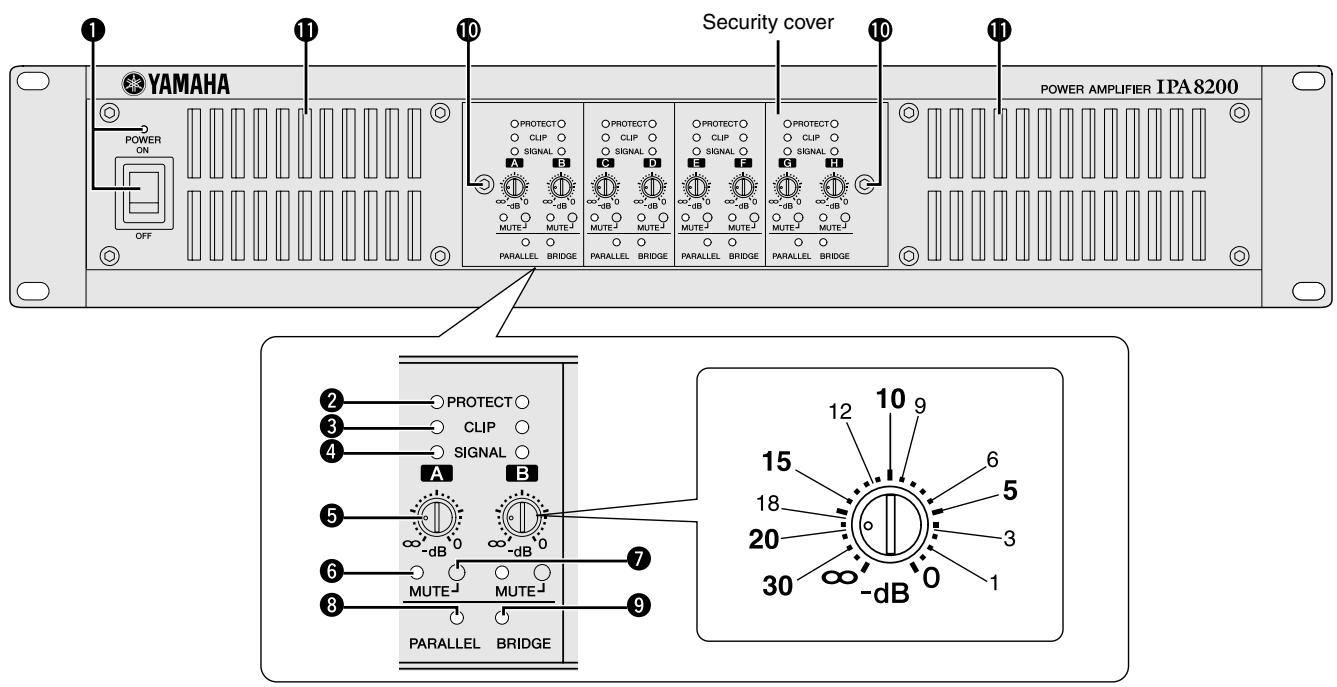
① POWER switch and indicator
Turns power to the unit on or off. The indicator lights green when the power is on.
② PROTECT indicator
When the protection system is active, the indicator lights red. When this is lit, the amplifier or power supply is automatically shut down, and no sound will be output from the speakers.
③ CLIP indicator
This indicator will light red when the output power exceeds 100 W for an 8Ω load or 200 W for a 4Ω load. When this is lit, the limiter will automatically operate.
④ SIGNAL indicator
This indicator will light green when the output level exceeds 2 Vrms. (This will light at 0.5 W or greater for an 8Ω load, 1W or greater for a 4Ω load.)
⑤ Attenuator
These are detented knobs that attenuate the input signal of each channel (A–H) over 41 steps in a range of 0 dB – - dB.
NOTE • To operate these knobs, use a slotted screwdriver with a blade no wider than 5.5 mm.
⑥ MUTE indicator
This will light red when mute is activated.
⑦ MUTE switch
This turns muting on/off for each channel. Use a thin rod to turn muting on/off.
⑧ PARALLEL indicator
This will light orange when the rear panel MODE switch is set to PARALLEL.
⑨ BRIDGE indicator
This will light orange when the rear panel MODE switch is set to BRIDGE.
⑩ Screw holes for security cover
If desired, you can use these two screw holes for attaching the included security cover to prevent the attenuator setting from being changed. Use the included Allen wrench and screws to attach the cover.
⑪ Air intakes
The amplifier uses forced-air cooling. The variable speed cooling fan draws air in from the front and exhausts it through the rear. The cooling fan operates at low speed when the heat sink temperature is below 65 ^ ( 149 ^ ), or at high speed when the temperature exceeds 65 ^ ( 140 ^ ). Please be sure that you do not block the air intakes or exhaust vents.
Rear Panel
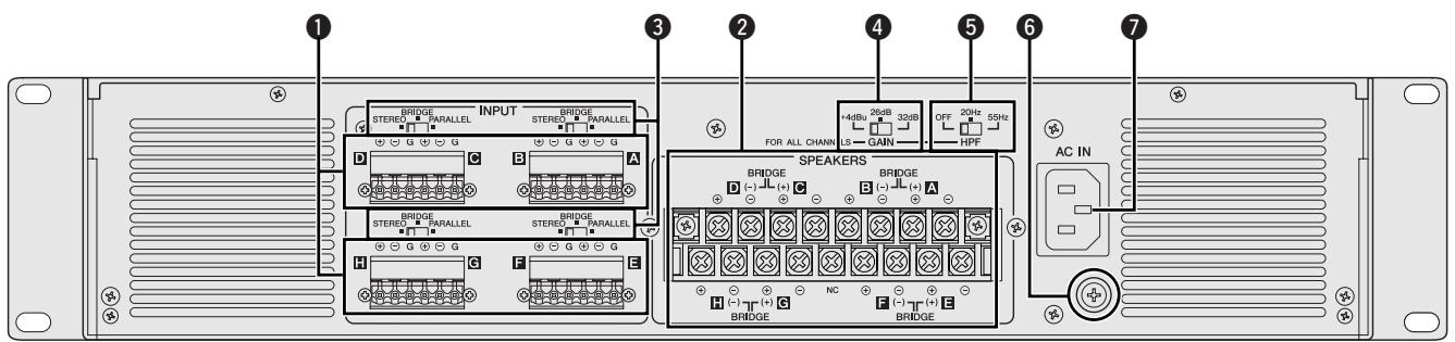
These are balanced input connectors. The included Euroblock connectors can be used to make connections here.
② SPEAKERS connectors
These are barrier strip type speaker output connectors.
NOTE
- If using BRIDGE mode, connect the speakers to the “+” pin of channels A/C/E/G and the “−” pin of channels B/D/F/H.
- Do not connect the pin marked NC located in the center of the bottom row of the barrier strip connectors.

Caution regarding output measurement
- To make the load to the power supply consistent and in particular to improve frequency response in the low range at very high volumes, channels B/D/F/H have been designed so that the signal is reversed in polarity just before the power amp stage and then output to the “-” pins of the corresponding SPEAKER terminals. (See the Block Diagram.)
If you measure the output, we recommend that you use an instrument that is compatible with balanced input. If you have an instrument that is compatible only with unbalanced input, use the “+” pin of channels B/D/F/H as ground, and apply a probe to the “-” pin and measure the output carefully. Using the probe improperly may cause the amplifier or instrument to malfunction.
③ MODE switches
These specify the amplifier's operation mode for each two channels.
- STEREO mode
Each channel (A–H) will operate independently.
- BRIDGE mode
The amplifiers will be bridged for pairs of adjacent channels (A-B, C-D, E-F, G-H), obtaining a high-power output.
- PARALLEL mode
The input signals will be input to the adjacent channels (A-B, C-D, E-F, G-H) as well.
④ GAIN switch
This switches the input sensitivity / gain for all channels together.
- +4 dBu: Sets the input sensitivity to +4 dBu.
• 26 dB: Sets the gain to 26 dB.
• 32 dB: Sets the gain to 32 dB.
⑤ HPF switch
Turns the high pass filter (20 Hz or 55 Hz) on/off. If this is set to 20 Hz or 55 Hz, the frequency components below that frequency will be cut by a 12 dB/oct. filter.
⑥ Ground screw
Hum and interference may be reduced in some cases by connecting the screw to an ground or to the chassis of the mixer, preamp, or other device in your system.
⑦ AC inlet
Connect this to the socket end of the included AC power cable. Connect the plug end of the AC power cable to an AC outlet of the correct voltage.

- If this device is to be rack mounted and transported frequently, be sure to support the rear end of the unit with mounting hardware that matches the size of the rack used.
Speakers can be connected to the IPA8200 using the following three mode settings. The total load impedance of the speakers that can be connected will depend on the mode setting. Do not use a setup that has a lower impedance than the minimum values shown below.
STEREO mode
If the rear panel MODE switch is set to STEREO, each channel will operate independently. You can use the front panel attenuators to adjust the attenuation for each channel independently.
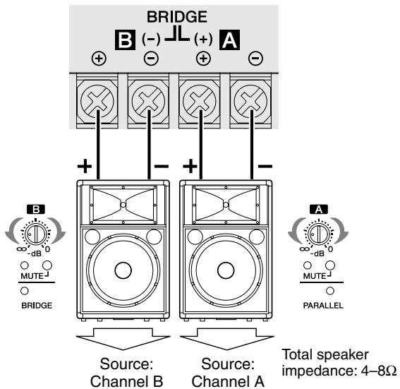
NOTE • Total speaker impedance must be 4–8Ω.
PARALLEL mode
If the rear panel MODE switch is set to PARALLEL, the input signals will be input to the adjacent channels (A-B, C-D, E-F, G-H) as well. Either of adjacent two channels can be used as an input connector. You can use the front panel attenuators to adjust the attenuation for each channel independently.
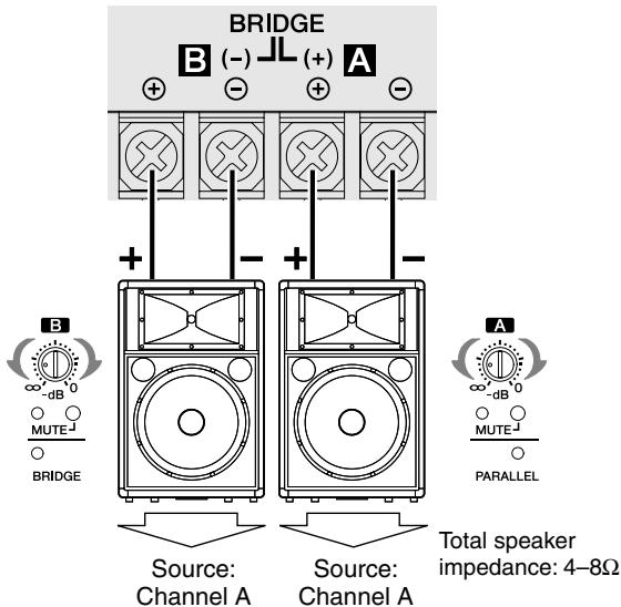
NOTE • Total speaker impedance must be 4–8Ω.
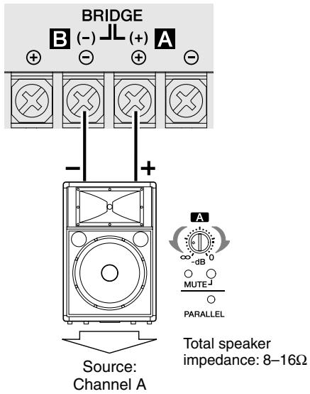
BRIDGE mode
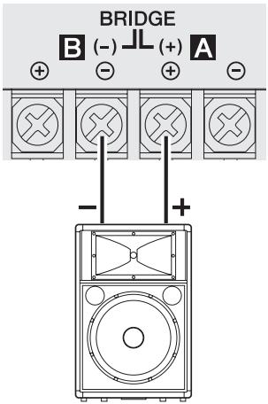
If the rear panel MODE switch is set to BRIDGE, the amplifiers will be bridged between adjacent pairs of channels (A-B, C-D, E-F, G-H), and the IPA8200 will operate as a high-power amplifier. Either of adjacent two channels can be used as an input connector. Use the front panel channel A/C/E/G attenuators to adjust the attenuation.
NOTE • If using BRIDGE mode, connect the speakers to the “+” pin of channels A/C/E/G and the “−” pin of channels B/D/F/H.
- Total speaker impedance must be 8–16Ω.
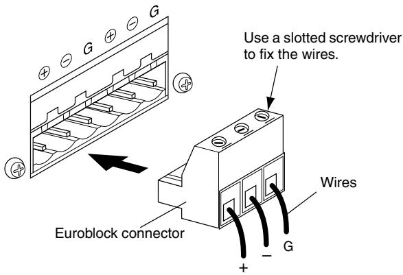
Input jack connections (Euroblock)
Please be sure to use the supplied Euroblock connectors. If you lose them, contact your nearest Yamaha dealer.
● Cable preparation
- To prepare the cable for attachment to a Euroblock connector, strip the wire as shown in the illustration, and use stranded wire to make connections. With a Euroblock connection, the stranded wire may be prone to breakage because of metal fatigue due to the weight of the cable or due to vibration. When rack-mounting your equipment, use a lacing bar when possible to bundle and fasten the cables.
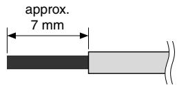
- If cables will be frequently connected and disconnected, as in the case of a portable installation, we recommend that you use ferrules with insulation sleeves. Use a ferrule whose conductor portion has an external diameter of 1.6 mm or less, and a length of approximately 7 mm (such as the AlO, 5-6WH made by the Phoenix Contact corporation).
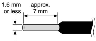

- If you use stranded wire, do not tin (plate with solder) the exposed end.
- If the wire insertion ports are closed, turn the screws on top of the connector counterclockwise to open the ports.
- Insert the wires into the appropriate ports, following the indication of the pole on the input terminal, and turn the screws on top of the connector clockwise to fasten the wires.
- Connect the Euroblock connector to the IPA8200's input jack.
Speaker connections (barrier strip)
From below, insert the spade lug all the way, and tighten the screw.
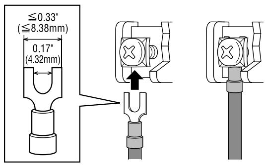
If using a bare conductor
Wrap the conductor around the barrier strip terminal as shown below, and tighten the screw. Be sure that the bare wire does not touch the chassis.
NOTE • Do not connect the pin marked NC located in the center of the bottom row of the barrier strip connectors.
- If using BRIDGE mode, connect the speakers to the “+” pin of channels A/C/E/G and the “−” pin of channels B/D/F/H.
| Indicator(s) | Possible cause | Remedy | Protection circuit |
| CLIP indicator is lit. | Output exceeds 100 W (8Ω) or 200 W (4Ω). | Lower the input level. | Limiter circuit will operate to protect the power amp and power supply. |
| PROTECT indicator is lit. | Speaker output connector is shorted. | Check whether the speaker output connector or speaker cable could be shorted, and then power-cycle the IPA8200.If the PROTECT indicator is still lit, contact your Yamaha dealer. | The protection circuit will operate to project the power amp and power supply. |
| The power amp section's heat sink temperature has exceeded 95°C or the power supply section's heat sink temperature has exceeded 85°C. | Check whether there might be blockage at the air intake or a ventilation problem inside the rack, and verify that the load impedance of the connected speakers is not below the rated value (4Ω or 8Ω/BRIDGE).Then wait until the unit's temperature has dropped, and power-cycle the unit.If the PROTECT indicator is still lit, contact your Yamaha dealer. | The protection circuit will operate to protect the power amp. | |
| A DC offset voltage is being output to the speaker output connector. | Consult your Yamaha dealer. | The protection circuit will operate to protect the speakers. |
General Specifications
| Output Power | 4Ω per channel | 200W x 8 | ||
| 8Ω per channel | 100W x 8 | |||
| 1kHz, THD+N=1% | 8Ω / BRIDGE | 400W x 4 | ||
| 20Hz-20kHz, THD+N=1% | 4Ω per channel | 180W x 8 | ||
| 8Ω per channel | 90W x 8 | |||
| 8Ω / BRIDGE | 360W x 4 | |||
| 1kHz, 20ms Burst | 4Ω per channel | 200W x 8 | ||
| 8Ω per channel | 100W x 8 | |||
| 8Ω / BRIDGE | 400W x 4 | |||
| Maximum Input Level | +24dBu | |||
| Input Impedance | 20kΩ(balanced), 10kΩ(unbalanced) | |||
| Input Sensitivity (dBu) | Switch Position | +4dBu | 26dB | 32dB |
| 8Ω, Att. max | Input sensitivity | +4dBu | +5.2dBu | -0.8dBu |
| Voltage Gain | Switch Position | +4dBu | 26dB | 32dB |
| Att. Max | Voltage Gain | 27.2dB | 26dB | 32dB |
| S/N Ratio | A-weighted | ≥100dB | ||
| THD+N | 1kHz, half power, 4Ω | ≤0.5% | ||
| Frequency Response | 1W, 8Ω | 20Hz-20kHz, +0dB, -1.5dB | ||
| Channel Separation | 1kHz, half power, 8ΩAtt. max, input 600Ω shunt | ≥60dB | ||
| Controls | Front Panel | POWER switch (rocker)MUTE switch (push ON/push OFF) x 8Attenuator (41positon) x 8 | ||
| Rear Panel | MODE switch (STEREO/BRIDGE/PARALLEL) x 4GAIN switch (+4dBu/26dB/32dB) x 1HPF switch (OFF/20Hz/55Hz) x 1 | |||
| Connectors | Input | Euroblock (balanced)/ch | ||
| Output | Barrier strip/ch | |||
| Power | AC inlet x 1 | |||
| Indicators | POWER x 1 (Green), PROTECT x 8 (Red),CLIP x 8 (Red), SIGNAL x 8 (Green), MUTE x 8 (Red),PARALLEL x 4 (Orange), BRIDGE x 4 (Orange) | |||
| Load Protection | POWER switch on/off | Output mute | ||
| DC-fault | Power supply shutdown | |||
| Amplifier Protection | Thermal | Output mute (heatsink temp ≥95°C) | ||
| Over current | Power supply shutdown | |||
| Power Supply Protection | Thermal | Power supply shutdown (heatsink temp ≥85°C) | ||
| Limiter Circuit | Clip limiting | Limiting level ≥100W@8Ω or 200W@4Ω | ||
| Cooling | High/Low two speed fan x 2 | |||
| AC Power Requirement | 120V, 220V–240V; 50Hz/60Hz | |||
| Power Consumption | 400W | |||
| Dimensions (W x H x D) | 480 x 88 x 406.5 mm (18-7/8 x 3-7/16 x 16 inch)(The depth is measured from the front panel surface to therear mounting hardware.) | |||
| Weight | 10.5kg (23.2 lbs) | |||
| Included Accessories | AC power cord (2.5m) x 1, Security cover x 1,Allen wrench x 1, Security cover attachment screw x 2,3-pin Euroblock connector x 8, Owner's manual | |||
• Half power = 3dB below rated power
- 0dBu = 0.775Vrms
- Specifications and descriptions in this owner's manual are for information purposes only. Yamaha Corp. reserves the right to change or modify products or specifications at any time without prior notice. Since specifications, equipment or options may not be the same in every locale, please check with your Yamaha dealer.
Block Diagram
flowchart
graph TD
    A["CHA C E G"] --> B["Attenuator HA"]
    B --> C["MUTE"]
    C --> D["HPF Fc=20Hz"]
    C --> E["HPF Fc=55Hz"]
    D --> F["Comp."]
    E --> G["COMP."]
    F --> H["BA"]
    G --> I["BA"]
    H --> J["Clip Level Detect"]
    I --> K["Level Detect"]
    J --> L["Pamp"]
    K --> M["Signal Level Detect"]
    L --> N["Output Filter"]
    M --> O["SPEAKERS"]
    N --> P["A, C, E, G"]
    O --> Q["B, D, F, H"]
    R["STEREO BRIDGE PARALLEL MODE"] --> B
    S["STEREO BRIDGE PARALLEL MODE"] --> C
    T["GAIN"] --> B
    U["GAIN"] --> C
    V["GAIN"] --> C
    W["ATTENUATOR HA"] --> X["MUTE"]
    X --> Y["HPF Fc=20Hz"]
    X --> Z["HPF Fc=55Hz"]
    Y --> AA["MPF"]
    Z --> AB["MPF"]
    AC["STEREO MODE"] --> AD["BP"]
    AE["BRIDGE PARALLEL MODE"] --> AF["BP"]
    AG["Power Supply"] --> AH["Capacitor"]
Dimensions
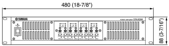
Unit: mm (inch)
Current Draw
| Line Current (A) | Power (W) | Thermal Dissipation | ||||||
| 100/120V | 230/240V | In | Out | Dissipated | Btu/h | kcal/h | ||
| Idle | 0.8 | 0.4 | 69 | 0 | 69 | 235 | 59 | |
| 1/8 power | 8Ω/ch | 1.9 | 1.0 | 189 | 100 | 89 | 304 | 77 |
| 4Ω/ch | 3.3 | 1.5 | 327 | 200 | 127 | 433 | 109 | |
| 1/3 power | 8Ω/ch | 3.9 | 1.8 | 389 | 267 | 122 | 417 | 105 |
| 4Ω/ch | 7.7 | 3.3 | 774 | 533 | 241 | 821 | 207 | |
1/8 power is typical of program material with occasional clipping. Refer to these figures for most applications.
1/3 power represents program material with extremely heavy clipping.
Test signal: Pink Noise, bandwidth limited from 22Hz to 22kHz
1W = 0.860kcal/h, 1BTU = 0.252kcal
Note that Line Voltage [V] x Line Current [A] = [VA], not equals to [W].
Inrush current: 11A (100V), 13A (120V), 26A (240V)
MEMO

Information for Users on Collection and Disposal of Old Equipment
This symbol on the products, packaging, and/or accompanying documents means that used electrical and electronic products should not be mixed with general household waste.
For proper treatment, recovery and recycling of old products, please take them to applicable collection points, in accordance with your national legislation and the Directives 2002/96/EC.
By disposing of these products correctly, you will help to save valuable resources and prevent any potential negative effects on human health and the environment which could otherwise arise from inappropriate waste handling.
For more information about collection and recycling of old products, please contact your local municipality, your waste disposal service or the point of sale where you purchased the items.
[For business users in the European Union]
If you wish to discard electrical and electronic equipment, please contact your dealer or supplier for further information.
[Information on Disposal in other Countries outside the European Union]
This symbol is only valid in the European Union. If you wish to discard these items, please contact your local authorities or dealer and ask for the correct method of disposal.
![YAMAHA IPA8200 - [Information on Disposal in other Countries outside the European Union] - 1](/content/2025/01/115255/images/f31104ece052c248964189feaa3db45e65ba41ec814e7206d4dddac43e89d530.jpg)
For details of products, please contact your nearest Yamaha representative or the authorized distributor listed below.
Yamaha Canada Music Ltd.
135 Milner Avenue, Scarborough, Ontario,
M1S 3R1, Canada
Tel: 416-298-1311
U.S.A.
Yamaha Corporation of America
6600 Orangethorpe Ave., Buena Park, Calif. 90620,
U.S.A.
Tel: 714-522-9011
CENTRAL & SOUTH AMERICA
MEXICO
PANAMA AND OTHER LATIN
AMERICAN COUNTRIES/
CARIBBEAN COUNTRIES
Yamaha Music Latin America, S.A.
Sherbourne Drive, Tilbrook, Milton Keynes,
MK7 8BL, England
Tel: 01908-366700
GERMANY
Yamaha Music Europe GmbH
Siemensstraße 22-34, 25462 Rellingen, Germany
Tel: 04101-3030
Branch Switzerland in Zürich
Seefeldstrasse 94, 8008 Zürich, Switzerland
Tel: 044-387-8080
AUSTRIA/BULGARIA
Yamaha Music Europe GmbH Branch Austria
Schleiergasse 20, A-1100 Wien, Austria
Tel: 01-60203900
CZECH REPUBLIC/HUNGARY/
ROMANIA/SLOVAKIA/SLOVENIA
Yamaha Music Europe GmbH
Branch Austria (Central Eastern Europe Office)
Schleiergasse 20, A-1100 Wien, Austria
Tel: 01-602039025
POLAND/LITHUANIA/LATVIA/ESTONIA
Yamaha Music Europe GmbH
Branch Poland Office
Yamaha Music Europe GmbH, Branch Italy
Viale Italia 88, 20020 Lainate (Milano), Italy
Tel: 02-935-771
SPAIN/PORTUGAL
Yamaha Music Europe GmbH Ibérica, Sucursal
en España
Ctra. de la Coruna km. 17, 200, 28230
Las Rozas (Madrid), Spain
Tel: +34-902-39-8888
GREECE
Philippos Nakas S.A. The Music House
147 Skiathou Street, 112-55 Athens, Greece
Tel: 01-228 2160
SWEDEN/FINLAND/ICELAND
Yamaha Music Europe GmbH Germany filial
Scandinavia
J. A. Wettergrens Gata 1, Box 30053
S-400 43 Göteborg, Sweden
Tel: 031 89 34 00
DENMARK
Yamaha Music Europe GmbH, Tyskland – filial
Denmark
Generatorvej 6A, DK-2730 Herlev, Denmark
Tel: 44 92 49 00
NORWAY
Yamaha Music Europe GmbH Germany -
Norwegian Branch
Grini Næringspark 1, N-1345 ∅sterås, Norway
Tel: 67 16 77 70
RUSSIA
Yamaha Music (Russia)
Room 37, bld. 7, Kievskaya street, Moscow,
121059, Russia
Tel: 495 626 5005
OTHER EUROPEAN COUNTRIES
Yamaha Music Europe GmbH
Siemensstraße 22-34, 25462 Rellingen, Germany
Tel: +49-4101-3030
AFRICA
Yamaha Corporation,
Asia-Pacific Sales & Marketing Group
Nakazawa-cho 10-1, Naka-ku, Hamamatsu,
Japan 430-8650
Tel: +81-53-460-2303
MIDDLE EAST
TURKEY
Yamaha Music Europe GmbH
LOB 16-513, P.O.Box 17328, Jubel Ali,
Dubai, United Arab Emirates
Tel: +971-4-881-5868
ASIA
THE PEOPLE'S REPUBLIC OF CHINA
Yamaha Music & Electronics (China) Co., Ltd.
2F, Yunhedasha, 1818 Xinzha-lu, Jingan-qu,
Shanghai, China
Tel: 021-6247-2211
INDIA
Yamaha Music India Pvt. Ltd.
Spazedge building, Ground Floor, Tower A, Sector
47, Gurgaon- Sohna Road, Gurgaon, Haryana, India
Tel: 0124-485-3300
INDONESIA
PT. Yamaha Musik Indonesia (Distributor)
PT. Nusantik
Gedung Yamaha Music Center, Jalan Jend. Gatot
Subroto Kav. 4, Jakarta 12930, Indonesia
Tel: 021-520-2577
KOREA
Yamaha Music Korea Ltd.
8F, 9F, Dongsung Bldg. 158-9 Samsung-Dong,
Kangnam-Gu, Seoul, Korea
Tel: 02-3467-3300
MALAYSIA
Yamaha Music (Malaysia) Sdn., Bhd.
Lot 8, Jalan Perbandaran, 47301 Kelana Jaya,
Petaling Jaya, Selangor, Malaysia
Tel: 03-78030900
SINGAPORE
Yamaha Music (Asia) PRIVATE LIMITED
Blk 202 Hougang Street 21, #02-00,
Singapore 530202, Singapore
Tel: 6747-4374
TAIWAN
Yamaha KHS Music Co., Ltd.
3F, #6, Sec.2, Nan Jing E. Rd. Taipei.
Taiwan 104, R.O.C.
Tel: 02-2511-8688
THAILAND
Siam Music Yamaha Co., Ltd.
4, 6, 15 and 16th floor, Siam Motors Building,
891/1 Rama 1 Road, Wangmai,
Pathumwan, Bangkok 10330, Thailand
Tel: 02-215-2622
VIETNAM
Yamaha Music Vietnam Company Limited
15th Floor, Nam A Bank Tower, 201-203 Cach
Mang Thang Tam St., Ward 4, Dist.3,
Ho Chi Minh City, Vietnam
Tel: +84-8-3818-1122
OTHER ASIAN COUNTRIES
Yamaha Corporation,
Asia-Pacific Sales & Marketing Group
Nakazawa-cho 10-1, Naka-ku, Hamamatsu,
Japan 430-8650
Tel: +81-53-460-2303
OCEANIA
AUSTRALIA
Yamaha Music Australia Pty. Ltd.
Level 1, 99 Queensbridge Street, Southbank,
Victoria 3006, Australia
Tel: 3-9693-5111
COUNTRIES AND TRUST
TERRITORIES IN PACIFIC OCEAN
Yamaha Corporation,
Asia-Pacific Sales & Marketing Group
Nakazawa-cho 10-1, Naka-ku, Hamamatsu,
Japan 430-8650
Tel: +81-53-460-2303

YAMAHA
Yamaha Pro Audio global web site:
http://www.yamahaproaudio.com/
Yamaha Manual Library: