
Comfort+ - Comfort+ Applique - Comfort Box - Comfort Style - Toilet SFA - Free user manual and instructions
Find the device manual for free Comfort+ - Comfort+ Applique - Comfort Box - Comfort Style SFA in PDF.
User questions about Comfort+ - Comfort+ Applique - Comfort Box - Comfort Style SFA
0 question about this device. Answer the ones you know or ask your own.
Ask a new question about this device
Download the instructions for your Toilet in PDF format for free! Find your manual Comfort+ - Comfort+ Applique - Comfort Box - Comfort Style - SFA and take your electronic device back in hand. On this page are published all the documents necessary for the use of your device. Comfort+ - Comfort+ Applique - Comfort Box - Comfort Style by SFA.
USER MANUAL Comfort+ - Comfort+ Applique - Comfort Box - Comfort Style SFA
This device may be used by children who are at least 8 years old, by people with reduced physical, sensory or mental capacities or those without knowledge or experience, if they are properly supervised and if the instructions relating to using the device completely safely have been given to them and the associated risks have been understood. Children must not play with the device. Cleaning and maintenance undertaken by the user must not be carried out by unsupervised children.
Electrical connections
All wiring must conform to BS7671, 1992 requirements for electrical installations.
The electrical installation must be carried out by a qualified electrical engineer.
The device's power supply must be connected to ground (class I) and protected by a high sensitivity differential circuit breaker (30 mA).
The connection must be used exclusively to provide the power to the product.
If the power cord is damaged, to prevent possible danger, it must be replaced by the manufacturer, customer service team or a similarly qualified individual.
The device must be placed so that the power supply socket is accessible.
Disconnect electrical power before working on the unit!
Sanicompact Comfort+
13.1
13.2
13.3
13.4
14
15
15.1
15.2
1. SÉCURITÉ
The device is developed according to the regulations and is subject to continuous quality control.
These performances require strict compliance with the installation and maintenance rules contained in these operating manual and in particular the indications marked by:
| Meaning | |
| DANGER | This term defines a high risk of danger, which can lead to death or serious injury, if not avoided. |
| NOTICE | This term characterises dangers to the machine and its proper operation. |
| ! | Warning of a general danger. The danger is specified by indications given in the table. |
| This symbol characterises dangers associated with the voltage and provides information on voltage protection. |
Please refer to installation standard EN 12056-4. Failure to comply with this operating and installation manual will result in the loss of warranty rights and rights to damages.
Disconnect electrical power before working on the unit!
2. DESCRIPTION
2.1 APPLICATIONS
Your compact macerator allows the discharge of waste water into a 032 mm pipe.
This appliance is for domestic use only.
Do not use for commercial or industrial applications.
The device has a high performance level, and is safe and reliable, provided all the rules for installation and maintenance in this notice are strictly followed.
2.2 OPERATING PRINCIPLE
Your wall-hung toilet is equipped with a pump shredder intended to grind up paper and organic waste.
Its system is installed in a wall-hung ceramic bowl with a frame without a cistern.
2.3 TECHNICAL DATA
| Maximum vertical discharge | 3 m |
| Maximum horizontal discharge | 30 m |
| Nominal power | 550 W |
| Frequency | 50-60 Hz |
| Voltage | 220-240 V |
| Electrical class | I |
| Protection index | IPX4 |
| Net weight | 43 kg |
2.4 PUMP CURVE
See figure 2.
2.5 VERTICAL PUMPING/HORIZONTAL PUMPING
See figure
2.6 SCOPE OF SUPPLY
See figure 4
2.7 DIMENSIONS
See figure
3. INSTALLATION
The fitting and working of your appliance must meet local regulations and the EN 12056-4 standard.
IMPORTANT
Before installation, check that the load-bearing wall can support the weight of the appliance (max. pull-out force = 120 kg).
3.1 PREPARATION OF THE SUPPORT FRAME
- Locate the fixing holes for the toilet bowl on the frame, depending on the bowl height chosen:
-
Select the height of your toilet bowl according to these values:
-
Seat height 475 mm = top fixing holes;
-
Seat height 445 mm = middle fixing holes;
-
Seat height 415 mm = bottom fixing holes.
-
Figure 5.1. Insert the threaded rods A into the fixing holes of the frame according to the following dimensions: L = 45 mm + X (X being the thickness of your cladding, plasterboard, tiles, box ...).
- Place the lock nut on the back of the frame and tighten the assembly.
- Figure 5.2. Screw the stainless steel inserts B onto the threaded rods.
- Figure 5.3. Insert the retaining brackets C into the mounting holes in the frame.
3.2 PREPARATION OF THE TOILET BOWL
Figure 6.1. Insert the retaining anchors D into the holes, from below.
-
Mesure the distance Y between the two retaining anchors.
Figure 6.2. Prepare the connection by attaching the elements K to the hose. Secure with hose clamps J.
Connection of a handbasin (option). Figure 6.3 -
Saw the closed inlet.
- Insert the hose L over the inlet, securing with a hose clamp I.
3.3 FIXING OF THE SUPPORT FRAME
- Figure 2. Use a pencil to mark the intended location of the frame (distance from the wall: 100mm ) and the angle bracket (not supplied). Provide at least 3 anchoring points at the feet, 2 of which must be on the wall side.
Figure 7.2. Remove the support frame and drill.
- Fit the appropriate fixings according to your wall (use 8x120 mm lag bolts; these parts are not supplied).
Figure 7.3 Attach the angle bracket.
- Figure 7.4. Use the nuts to adjust the dimension between the wall and the edge of the frame; the distance between the wall and the edge of the frame must be 100mm .
- Check the alignment between the wall and the frame, the frame must be parallel to the wall.
Figure 7.5 Attach the support frame.
3.4 WATER SUPPLY
See figure 8.1
The water supply is in the upper part of the frame.
The water supply must be connected to a 14/16 copper pipe with a 20/27 male threaded connection (not supplied).
Secure the copper pipe with a clamp to prevent any movement when connecting the device.
It is essential to install an accessible 1/4 turn shut-off valve on the water inlet to facilitate any intervention
3.5 SEWAGE DISCHARGE
See figure 8.2
Discharge the waste water with a PVC pipe 32 mm.
Maintain a slope of 1% on all horizontal sections.
Install the discharge pipe at a distance from the floor of :
- 340 mm for a bowl 475 mm from the floor (①);
- 310 mm for a bowl 445 mm from the floor (②);
- 280 mm for a bowl 415 mm from the floor (③).
- Secure the discharge pipe with a clamp.
3.6 POWER SUPPLY
DANGER
| A | Electrical connection work performed by an unqualified individual. Risk of death by electric shock! ⇒The electrical connection must be performed by a qualified and licensed electrician. ⇒The electrical installation must meet the current standards in the country (UK: BS 7671). |
The electrical supply must be used exclusively to power the appliance and must be connected to a differential circuit breaker set to 30mA , protected by a 5 A fuse.
4. FITTING THE WALL CLADDING
4.1 REMOTE BUTTON
option for Sanicompact® Comfort+ Applique,
Sanicompact® Comfort Box, Sanicompact® Comfort Style
When installing a box panel, it is possible to move the control button to the top of the box panel.
Figure 9.1. Spread out the two lugs on each side.
Figure 9.2 Remove the capsule.
Figure 9.3. Unscrew the nut.
- Remove the entire button and proceed in reverse order to place it in the hole designed for this purpose on your box panel.
- Seal the hole in the bowl with the supplied cover.
Continue with the preparation of the wall cladding:
-
Sanicompact® Comfort+ Applique, Sanicompact® Comfort Box, Sanicompact® Comfort Style : box panel cladding go to paragraph 4.2.
-
Sanicompact® Comfort+: not provided board cladding (like plasterboard) go directly to paragraph 4.5.
4.2 PREPARATION OF THE BOX PANEL
(Sanicompact® Comfort+ Applique, Sanicompact® Comfort Box, Sanicompact® Comfort Style)
-
Figure 10. Prepare a cut-out to allow the water injection passage according to the previously selected seat height:
-
for a half-height adjustment, the cut-out is 40 ~mm ;
- for an adjustment in the upper position, the cut-out is 70 ~mm ;
-
for a low adjustment, no cut-out is necessary.
-
Continue with the fitting of the box panel cladding:
-
Sanicompact® Comfort+ Applique, Sanicompact® Comfort Box
go to paragraph 4.3.
- Sanicompact® Comfort Style go directly to paragraph 4.4.
4.3 FITTING THE BOX PANEL FOR Sanicompact
Comfort+ Applique AND Sanicompact® Comfort Box
- Figure 11.1. Mark out the location of the evacuation passage on the box panel
- Cut the box panel to create the evacuation passage.
- Figure 11.2. Glue two strips on each side of the frame as shown above.
- Figure 11.3. Glue the two remaining strips on each side to the inside of the box panel as shown.
- Figure 11.4. Insert the box panel up to the wall, apply pressure to the hanging strips so that they stick together.
- Figure 11.5. Remove the protective film and complete the installation with a silicone seal around the casing if necessary.
- Finalize the complete installation: go directly to paragraph 5.
4.4 FITTING THE BOX PANEL FOR Sanicompact
Comfort+ Style
- Figure 12.1. Mark out the location of the evacuation passage on the box panel
- Using a hole saw or a jigsaw fitted with a steel blade, cut the box panel to create the evacuation passage.
- Figure 12.2. Insert the box panel right up to the wall using the inside of the box brackets to centre the box horizontally.
- Figure 12.3. Remove the protective film and complete the installation with a silicone seal around the casing if necessary.
- Finalize the complete installation: go directly to paragraph 5.
4.5 PREPARATION AND ASSEMBLY OF BOARD
CLADDING FOR Sanicompact® Comfort+ (Figure 13)
-
Place the plasterboard facing the frame previously fixed to the wall.
-
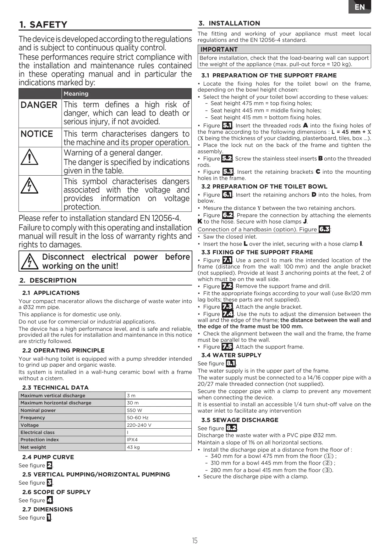
Figure 13.1. Locate and drill the position of the bowl support rods on the plasterboard.
-
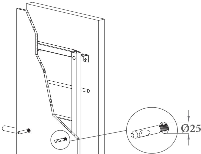
Place the foam gasket F on the cladding wall by positioning the 2 holes on the bowl support rods.
-
Figure 13.2. Trace the inner contour of the foam gasket on the cladding wall.
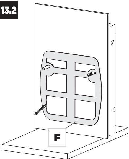
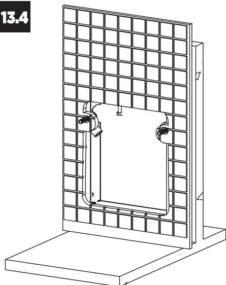
Figure 13.3 Remove the foam gasket and cut the plasterboard according to the outline. - Figure 13.4. Finish the complete installation (possibly tiling) of your cladding wall.
Note: If you are tiling your cladding wall, you must cut the tiles in the same way as the plasterboard.
5. CONNECTING AND INSTALLING THE TOILET
BOWL
IMPORTANT
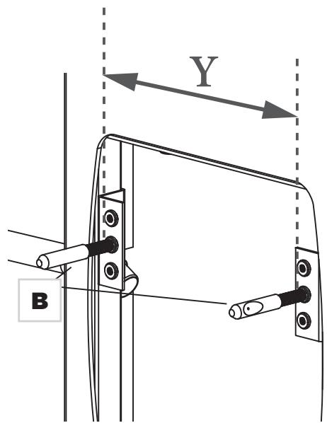
Before carrying out the connections, check that the threaded rods A are correctly screwed into the frame and that the inserts B are positioned as shown in figure 15.1 (with the hollow facing outwards).
- Reposition the foam gasket that will serve as a support between the bowl and the wall.
- Present the bowl supported on its axles.
5.1 CONNECTING THE DISCHARGE PIPE
Note: Use the polystyrene shim included in your packaging to support the ceramic bowl during this operation.
- Insert the hose K into the discharge pipe.
- Secure the hose by using the clamp supplied.
Option: Connection of a handbasin (figure 6-3)
- Connect the hand basin outlet 40 mm to the hose L.
- Secure the connection with a clamp J (see figure 7.2).
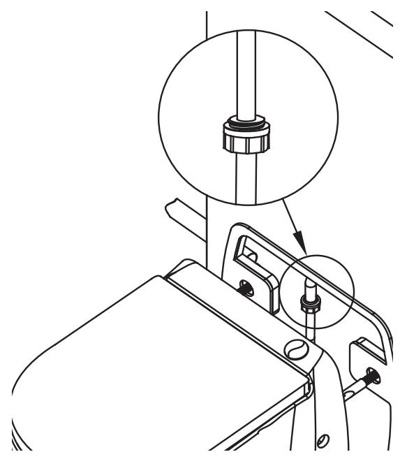
5.2 CONNECTING TO THE WATER SUPPLY
Figure 14. Connect the end of the water supply hose to the previously made connection.
5.3 FITTING THE TOILET BOWL
Figure 15.1. Adjust the distance between the inserts using the measurement Y from section 3.2.
- Tighten the double nuts according to the measurement Y.
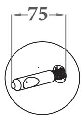
- Once the connections have been made, adjust the inserts B so
that the end of the insert is positioned 75mm from your cladding.
- The hollows must point outwards.
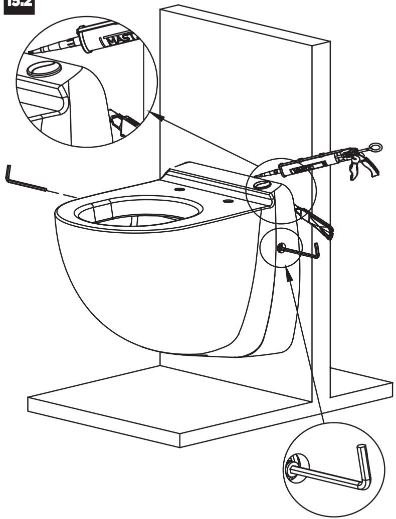
- Figure 15.2. Replace the foam gasket F and place the bowl on the bowl support rods.
- Position a grub screw G in the hole on each side.
- Tighten the grub screws with the supplied wrench H until the bowl is completely immobile.
- Close with the hole covers M.
6. FUNCTIONAL TEST AND COMMISSIONING
- Plug in the device.
- Fully open the water inlet in order to rinse properly.
- Start the normal cycle by pressing the dark grey part.
- Throw a few pieces of toilet paper in the bowl and repeat the flush cycle.
- Check that the connections do not leak.
- Carry out several functional tests.
Handbasin option:
- Let the tap of the handbasin run, the device should start automatically.
- Check that the connections do not leak.
7. USE AND PRECAUTIONS
7.1 PRECAUTIONS FOR USE
DANGER

Never use the device in the event of a power failure!
NOTICE

Do not use the device to dispose foreign bodies such as periodical swabs, condoms, rags, cotton, solvents, oil, etc. that could damage the device.
Such use will invalidate the warranty.
IMPORTANT
The quality of the rinsing of the bowl depends on the water pressure. For optimum rinsing, the outlet pressure of your tap must be at least 1.7 bar dynamic (and maximum 10 bar).
The compact macerator is used like a conventional toilet and requires minimal maintenance (see 8. Maintenance).
In the regions where the water of the network is dirty or sandy, we recommend inserting an additional filter between the stop valve and the device, in order to prevent complicated maintenance work should be solenoid valve become clogged.
Sanicompact® is controlled by an electronic programmer. The operating life varies according to the cycle chosen:
- Eco cycle (light grey button)
- Normal cycle (dark grey button)

If necessary, you have the option of extending the rinsing duration if the default setting is not sufficient (low supply pressure).
Modifying the programme:
- Press and hold a button for more than 5 seconds. The motor runs briefly twice: indicating that you have entered programming mode.
- A press on the dark grey button or a long press on the light grey button increases the duration of the rinse cycle by 2 seconds. Each press is confirmed by the motor running briefly.
- A short press on the light grey button reduces the duration of the rinse cycle by 2 seconds. Each press is confirmed by the motor running briefly.
- To exit programming mode: take no action for 7 seconds. The motor runs briefly twice indicating that you have exited programming mode.
Note: the modified cycle remains in the memory even after a power failure.
In case of excessive use, the device is protected by a thermal probe.
7.3 HANDBASIN OPERATION (OPTION)
IMPORTANT
Ensure you check that your Sanicompact® connected basin is closed after use and does not leak.
To evacuate sewage from a handbasin: start-up takes place automatically.
8. MAINTENANCE
8.1 DESCALING
IMPORTANT
To prevent the build-up of scale inside the appliance, regular.
descaling is recommended.
To descale and clean the shredder and bowl, use the special SFA descaler regularly, which is designed to remove scale while respecting the internal parts of your device.
8.2 INSPECTION
The proper functioning of the installation must be checked by the user once a month by observing at least two operating cycles.
8.3 PROLONGED ABSENCE
NOTICE

In case of prolonged absence, it is imperative to cut off the general water supply and to protect the installation against frost.
9. STANDARDS
This appliance conforms to EN 12050-3 and the European standards concerning electrical safety and electromagnetic compatibility.
DoP (Declaration of Performance) available on our website in the product file.
10.FAULT FINDING / REMEDIES
Disconnect electrical power before working on the unit!
| SYMPTOMS | PROBABLE CAUSES | REMEDIES |
| After pressing the flush button, the cycle does not start up. | The electrical power supply is not active. | Restore the electrical supply. |
| The electrical power supply is defective. | Check the electrical power supply. | |
| The motor or the control system is defective. | Ask an approved repair agent to intervene. | |
| The cycle starts but only a small amount of water drains from the bowl. | The inlet filter of the solenoid valve (28) is clogged. | Clean the filter of the solenoid valve. |
| Input water flow is insufficient. | • Increase the rinsing time (programming). • Modify the installation. | |
| The cycle starts but the water does not drain from the bowl. | Your stop valve is closed. | Open your stop valve. |
| The solenoid valve (28) is fault. | Contact SFA customer services. | |
| The cycle runs normally, the motor runs but the water in the bowl is drawn in slowly or not at all. | Input water flow is insufficient. | Clean or replace the U-bend valve (23). |
| The U-bend valve (23) leaks. | ||
| The cycle runs normally, but a lot of water remains in the bowl. | The outlet height is too great. | Modify the installation. |
| The non-return valve leaks. | The non-return valve leaks. | |
| The motor runs with a rattling noise or buzzes and does not run. | Motor blocked by a foreign body. | Remove the foreign body. |
| Problem with the motor or control system. | Consult an approved engineer. | |
| The device works intermittently. | The connected sanitary devices leak. | Check the upstream installation. |
| The non-return valve leaks. | lean or replace the anti-return valve. | |
| Odours come from the U-bend of the hand washer. | The U-bend of the hand washer is empty. | Install a vacuum breaker. |
| The water of the hand washer does not drain automatically. | Clogged hand washer U-bend. | Clean the U-bend. |
| Problem with the automatic control system. | Consult an approved engineer. |
11. DISPOSAL

The device must not be disposed of as household waste and must be disposed of at a recycling point for electrical equipment. The device's materials and components are
reusable. The disposal of electrical and electronic waste, recycling and recovery of any form of used appliances
contribute to the preservation of our environment.
12. WARRANTY CONDITIONS
The device is guaranteed for two years from the date of purchase subject to installation, use and maintenance in accordance with this manual.
Only the evacuation of toilet paper, faeces and sanitary water are covered by this warranty. Any damage caused to the appliance by the shredding of foreign bodies such as cotton, tampons, sanitary pads, wipes, foodstuffs, condoms, hair, objects made of metal, wood or plastic, or the pumping of liquids such as solvents or oils are not covered by the warranty.
1. SICHERHEIT
2.5 RELATIE OPVOERHOOGTE/AFVOERCAPACITEIT
Zie afbeelding
2.6 LEVERINGSOMVANG
Zie afbeelding 4
2.7 AFMETINGEN
Zie afbeelding 1.
3. ZELFDRAGEND FRAME INSTALLEREN
3.5 AANSLUITING VAN DE AFVOER
Zie afbeelding 3.2
4.1 KNOP VERPLAATSEN
OPTIE VOOR Sanicompact® Comfort+ Applique, Sanicompact® Comfort Box, Sanicompact® Comfort Style
(Call from a land line)
Fax: 020 8842 1671
Ireland
Tel: 1850 23 24 25
(Low Call)
Fax: +353 46 97 33093
Deutschland
Tel: 0800 82 27 82 0
Fax: (06074)30928-90
Italia
Tel: +39 0382 6181
Fax: +39 0382 618200
Espana
Tfno: +34 93 544 60 76
Portugal
Tel: +351 219 112 785
sfa@sfa.pt
technical@saniflo.com.au
New Zealand
Phone: 0800107264
technical@saniflo.co.nz
South Africa
Tel: +27 (0) 21 286 0028
Viet Nam
Tel: +84 (0)977889364
India
Tel: +91 (0)22 6993 1900
service@sfapumps.in
Service information : www.sfa.biz