
20VMPS2-85.1 - Circular saw DEXTER - Free user manual and instructions
Find the device manual for free 20VMPS2-85.1 DEXTER in PDF.
User questions about 20VMPS2-85.1 DEXTER
0 question about this device. Answer the ones you know or ask your own.
Ask a new question about this device
Download the instructions for your Circular saw in PDF format for free! Find your manual 20VMPS2-85.1 - DEXTER and take your electronic device back in hand. On this page are published all the documents necessary for the use of your device. 20VMPS2-85.1 by DEXTER.
USER MANUAL 20VMPS2-85.1 DEXTER
text_image
Technical diagram of a mechanical assembly with labeled parts A, B, C, D and X1, including exploded view and component details.∅85x15

text_image
DEXTERE X1
natural_image
Abstract line pattern with intersecting curved lines (no text or symbols)∅85x15

text_image
DEXTERF X1
natural_image
Pattern of diamond-shaped metalwork on a diagonal line, no text or symbols present∅85x15
natural_image
Circular diagram with labeled components and directional arrows, no readable text or symbolsG X1
natural_image
Line drawing of a brick wall pattern with uniform rectangular tiles (no text or symbols)
Attention danger / Atención: Peligro / Atenção perigo / Attenzione pericolo / Прогохή κίνδυνος / Uwaga niebezpieczeństwo / Увара! Небезпечно! / Atenție, pericol / Caution danger

Hors tension / Apagado / Desligado da alimentação / Fuori tensione / Ектоç táσης / Odłączenie zasilania / Не під напругою / Scoatere de sub tensiune / Power off

Mise sous tension / Puesta en tensión / Ligação da alimentação / Messo sotto tensione / Σύνδεση με το ηλεκτρικό δίκτυο / Włączenie zasilania / Під'єднання під напругу / Punere sub tensiune / Power up

FR: Montage / ES: Montaje / PT: Montagem / IT: Montaggio / EL: Συναρμολόγηση / PL: Montaż / UA: 36ipka / RO: Montaj / EN: Assembly

7→15

FR: Utilisation / ES: Utilización / PT: Utilização / IT: Uso / EL: Xrígón / PL: Użytkowanie / UA: Використання RO: Utilizare / EN: Use

16→21

EN: Legal & Safety Instructions

22→110
i
text_image
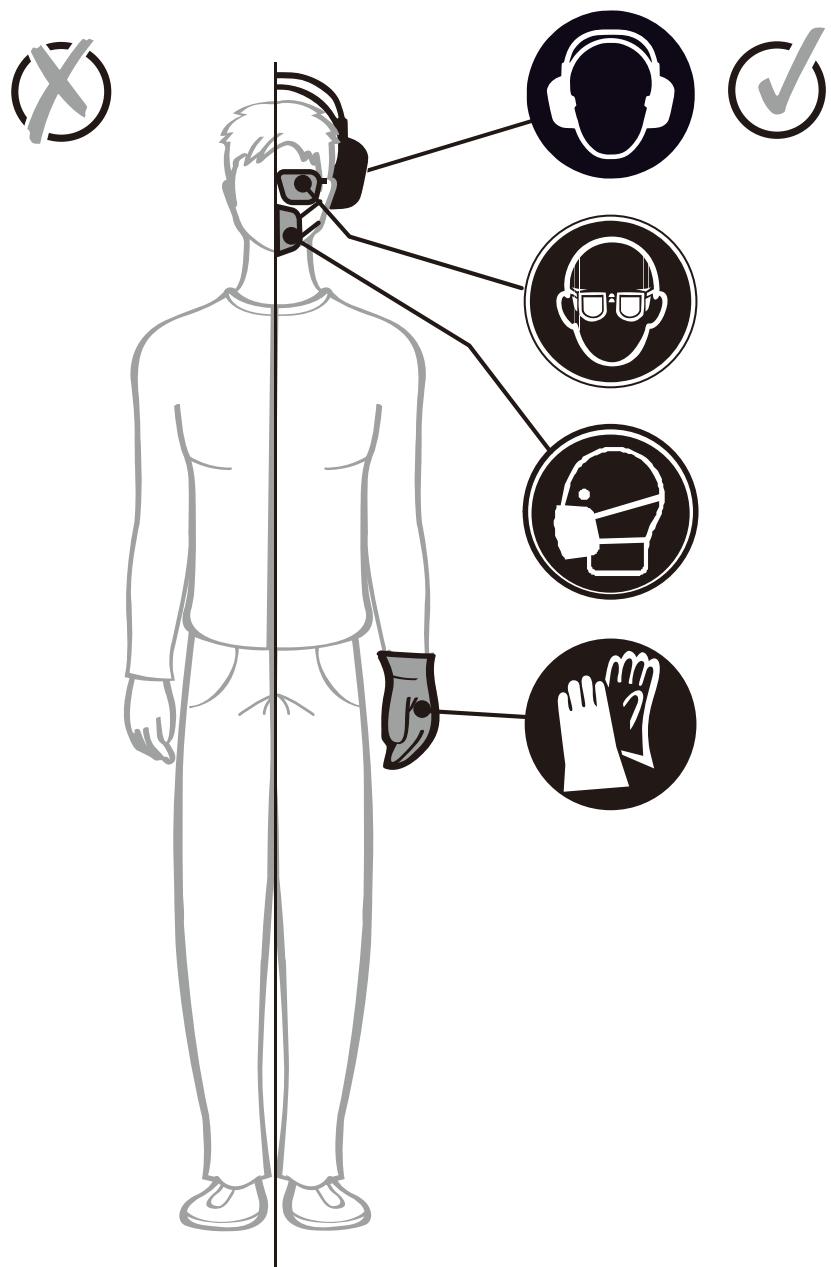
Diagram illustrating human body posture with labeled icons for hearing, safety, and hand gestures
1
natural_image
Technical line drawing of a mechanical assembly with a lever and gear mechanism (no text or symbols)2
natural_image
Technical line drawing of a mechanical assembly with no visible text or symbols3
text_image
Technical diagram of a mechanical device with numbered parts and an inset showing hand tool interacting with a component.4
text_image
Technical diagram of a CNC machine with labeled parts and a numbered annotation indicating assembly step 35
natural_image
Technical line drawing of a mechanical assembly with no visible text or symbols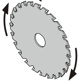
natural_image
Diagram of a gear with teeth and rotational arrows indicating motion (no text or symbols)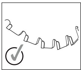
natural_image
Simple line drawing of a zigzag chain with a checkmark (no text or symbols)6
text_image
Technical diagram of a mechanical assembly with numbered parts and tool icons for inspection or repair.7
text_image
DEXTERX 10 5 -0 -0 10 mm8
text_image
DEXTEX ① ② 27 mm9
text_image
Technical diagram showing three steps of a sewing machine: base, side view, and top view with labeled components.10

natural_image
Technical illustration of a vacuum cleaner and its internal components, showing fluid flow path (no text or symbols)11
text_image
Technical diagram showing a hand operating a mechanical device with labeled parts and a magnified view of the component.12
text_image
Laser ②13
natural_image
Technical line drawing of a mechanical assembly with a ruler and bracket (no text or symbols)14
natural_image
Technical line drawing of a mechanical assembly with no visible text or symbols15
text_image
Technical diagram showing a hand operating a car gear shift knob with numbered parts and an open lock icon labeled ②.16
text_image
Technical diagram of a sewing machine with labeled parts and a numbered callout pointing to the component.
17
natural_image
Technical line drawing of a mechanical tool with gear and base, no text or symbols present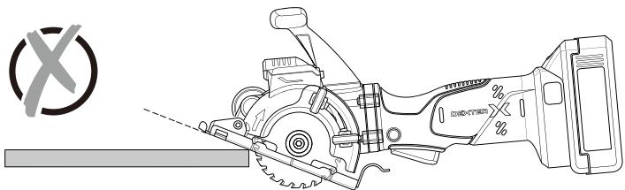
natural_image
Technical line drawing of a saw cutting machine with a circular symbol and cross mark (no text or labels)18
text_image
5cm19
text_image
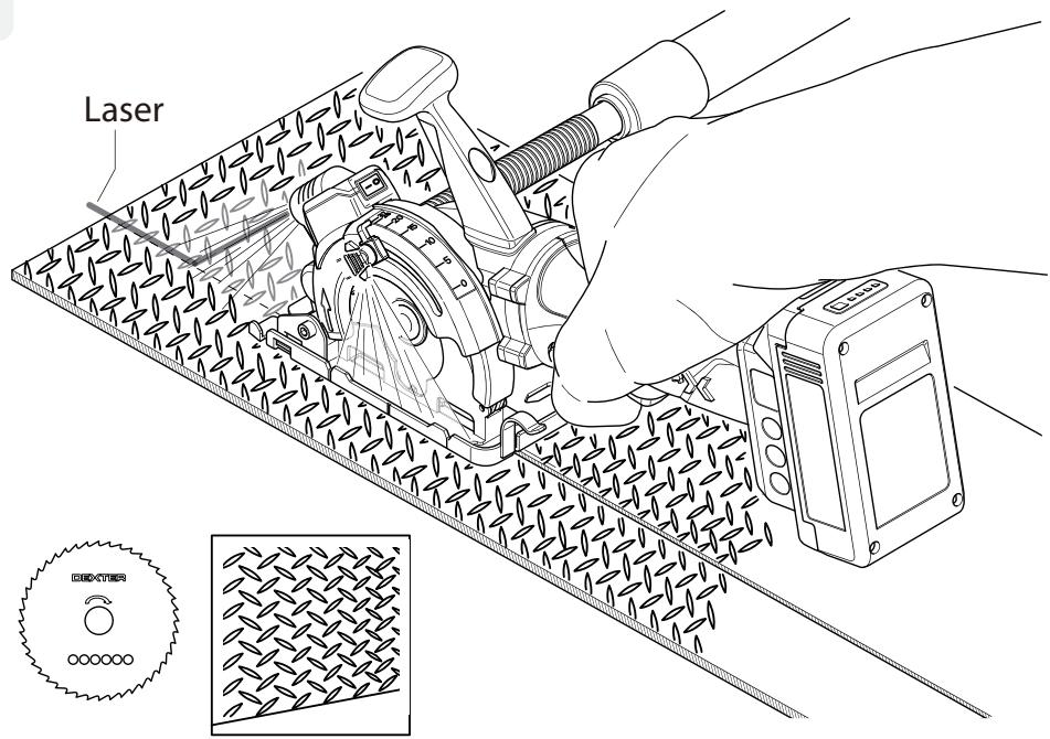
Laser20
natural_image
Diagram showing a gear and a wooden saw blade with internal flow lines (no text or symbols)
text_image
Laser21
text_image
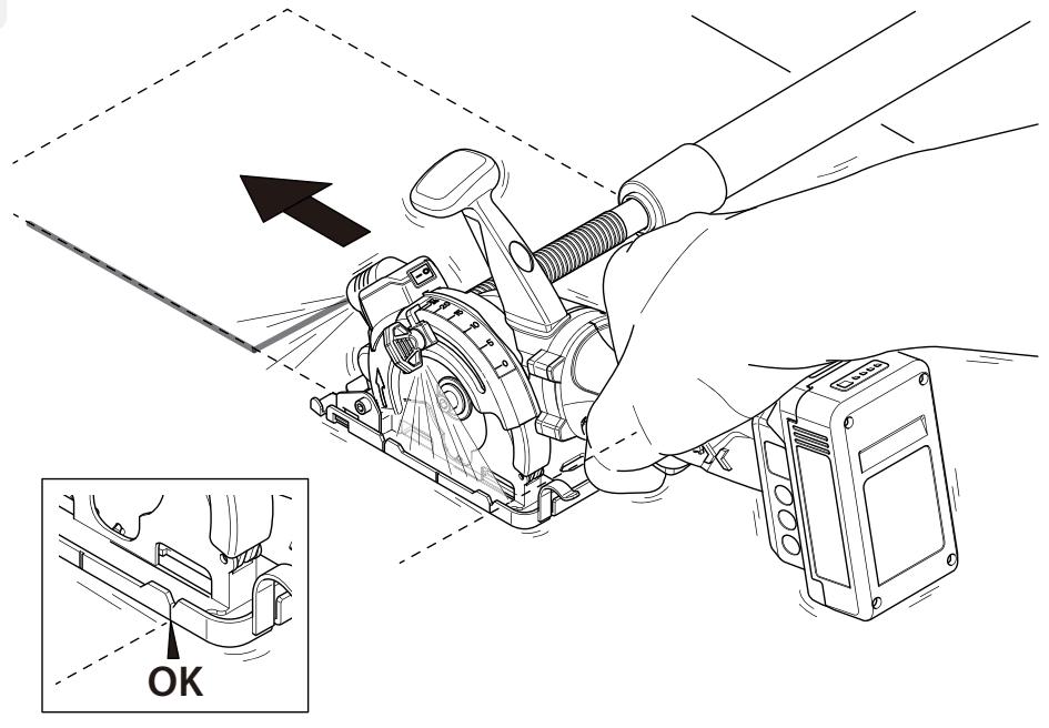
Technical diagram showing a hand operating a mechanical device with an arrow indicating direction and an inset highlighting the 'OK' (OK) state.22
text_image
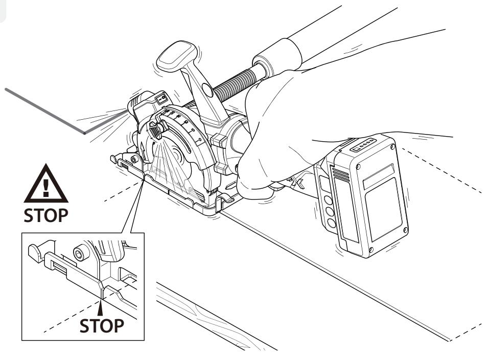
STOP STOP23
natural_image
Technical line drawing of a mechanical assembly with tool and component details (no readable text or symbols)24
text_image
Laser CROCCUMBER25
text_image
Laser EFFECTED26
text_image
Laser27
text_image
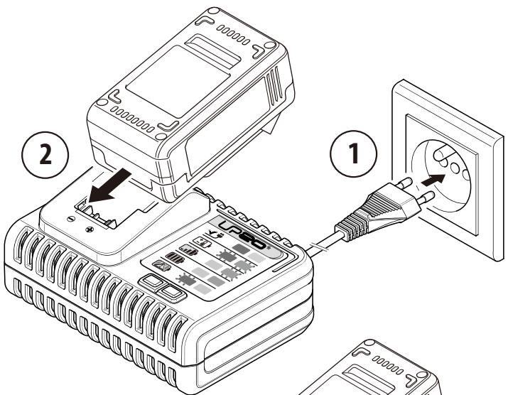
Diagram showing two steps of a power connector installation: one with a plug inserted into a socket, the other with a plug inserted into an electrical outlet.3

natural_image
Line drawing of a battery pack and its internal components (no text or symbols)
4
natural_image
Line drawing of a battery pack with a top component and internal circuit board (no text or symbols)1. UTILISATION PRÉVUE
Courant continu (CC)

text_image
Technical diagram of a mechanical assembly with numbered components and exploded viewstext_image
Exploded view diagram of a mechanical assembly with numbered parts for identification- VUE ÉCLATÉE AVEC LISTE DES PIÈCES
text_image
Technical diagram of a mechanical assembly with numbered components and an inset view of the gear mechanism.text_image
Exploded view diagram of a mechanical assembly with numbered parts for identificationtext_image
Technical diagram of a mechanical assembly with numbered components and an inset view of the gear mechanism.text_image
Exploded view diagram of a mechanical assembly with numbered parts for identification- PERSPETIVA EXPLODIDA E LISTA DE PEÇAS
UP20, Lexman UP20, and Dexter UP20

text_image
Technical diagram of a mechanical assembly with numbered components and an inset view of the gear mechanism.text_image
Exploded view diagram of a mechanical assembly with numbered parts for identification- VISTA ESPLOSA ED ELENCO DEI PEZZI DI RICAMBI
text_image
Technical diagram of an engine assembly with numbered components and a close-up view of the internal gear mechanism.text_image
Exploded view diagram of a mechanical assembly with numbered parts for identificationtext_image
Technical diagram of an engine assembly with numbered components and a close-up view of the internal gear mechanism.text_image
Exploded view diagram of a mechanical assembly with numbered parts for identification- PERSPEKTYWICZNY WIDOK EKSPLODUJĄCY & LISTA CZĘŚCI ZAMIENNYCH
text_image
Technical diagram of a mechanical assembly with numbered components and exploded viewstext_image
Exploded view diagram of a mechanical assembly with numbered parts for identificationtext_image
Technical diagram of a mechanical assembly with numbered components and an inset view of the gear mechanism.text_image
Exploded view diagram of a mechanical assembly with numbered parts for identification- VEDERE DETALIATĂŞI LISTAPIESELOR DE SCHIMB
This machine is designed for ripping and cross-cutting wood and other materials in straight cutting lines, while resting firmly on the work piece (Wood, Metal, Aluminium and PVC)
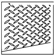
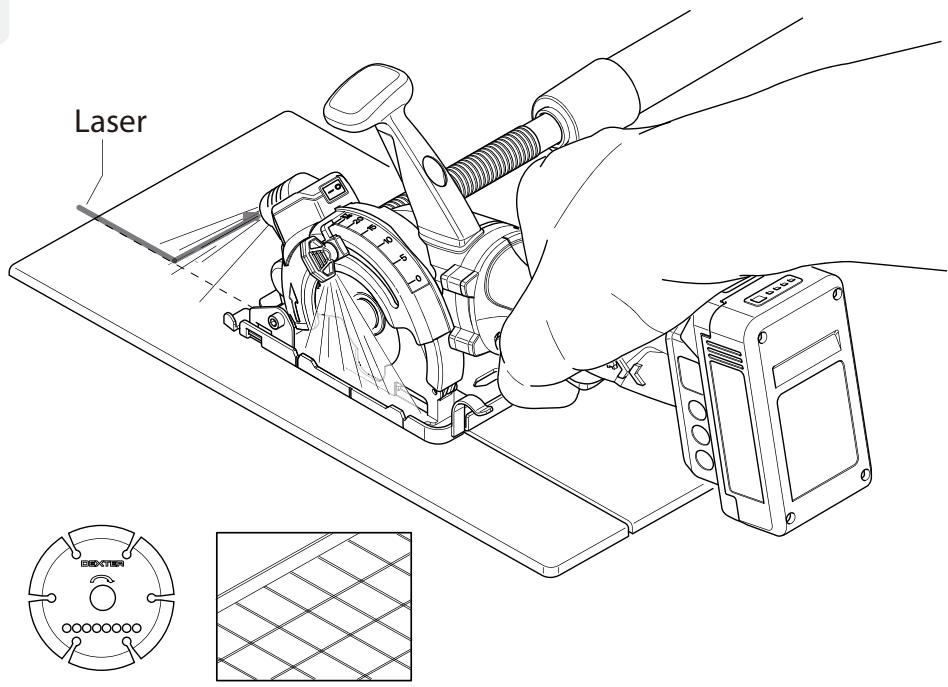
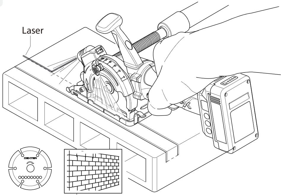
If matched diamond saw blade, these machines are intended to cut materials such as tile & red brick.
Do not use machines, tools and accessories for additional applications (see manufacturer's instructions) or for works other than those for which they are designed for. The blade recommendations are to be observed.
2. SPECIFIC SAFETY WARNINGS
CUTTING PROCEDURES
A. DANGER: Keep hands away from cutting area and the blade. Keep your second hand on auxiliary handle, or motor housing. If both hands are holding the saw, they cannot be cut by the blade.
B. Do not reach underneath the workpiece. The guard cannot protect you from the blade below the workpiece.
C. Adjust the cutting depth to the thickness of the workpiece. Less than a full tooth of the blade teeth should be visible below the workpiece.
D. Clamp workpiece with a clamping device. Never hold the workpiece in your hands or across your leg while cutting. Secure the workpiece to a stable platform. It is important to support the work properly to minimize body exposure, blade binding, or loss of control.
E. Hold the power tool by insulated gripping surfaces, when performing an operation where the cutting tool may contact hidden wiring. Contact with a «live» wire will also make exposed metal parts of the power tool «live» and could give the operator an electric shock.
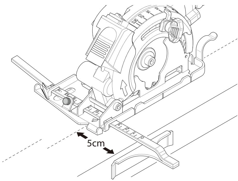
F. When ripping always use a rip fence or straight edge guide. This improves the accuracy of cut and reduces the chance of blade binding.
G. Always use blades with correct size and shape (diamond versus round) of arbour holes. Blades that do not match the mounting hardware of the saw will run off centre, causing loss of control.
H. Never use damaged or incorrect blade washers or bolt. The blade washers and bolt were specially designed for your saw, for optimum performance and safety of operation.
KICKBACK CAUSES AND RELATED WARNINGS FOR ALL SAWS
- kickback is a sudden reaction to a pinched, jammed or misaligned saw blade, causing an uncontrolled saw to lift up and out of the workpiece toward the operator;
- when the blade is pinched or jammed tightly by the kerf closing down, the blade stalls and the motor reaction drives the unit rapidly back toward the operator;
- if the blade becomes twisted or misaligned in the cut, the teeth at the back edge of the blade can dig into the top surface of the wood causing the blade to climb out of the kerf and jump back toward the operator.
Kickback is the result of saw misuse and/or incorrect operating procedures or conditions and can be avoided by taking proper precautions as given below.
A. Maintain a firm grip with both hands on the saw and position your arms to resist kickback forces. Position your body to either side of the blade, but not in line with the blade. Kickback could cause the saw to jump backwards, but kickback forces can be controlled by the operator, if proper precautions are taken.
B. When blade is binding, or when interrupting a cut for any reason, release the trigger and hold the saw motionless in the material until the blade comes to a complete stop. Never attempt to remove the saw from the work or pull the saw backward while the blade is in motion or kickback may occur. Investigate and take corrective actions to eliminate the cause of blade binding.
C. When restarting a saw in the workpiece, centre the saw blade in the kerf so that the saw teeth are not engaged into the material. If a saw blade binds, it may walk up or kickback from the workpiece as the saw is restarted.
D. Support large panels to minimize the risk of blade pinching and kickback. Large panels tend to sag under their own weight. Supports must be placed under the panel on both sides, near the line of cut and near the edge of the panel.
E. Do not use dull or damaged blades. Unsharpened or improperly set blades produce narrow kerf causing excessive friction, blade binding and kickback.
F. Blade depth and bevel adjusting locking levers must be tight and secure before making the cut. If blade adjustment shifts while cutting, it may cause binding and kickback.
G. Use extra caution when sawing into existing walls or other blind areas. The protruding blade may cut objects that can cause kickback.
H. Always observe that the lower guard is covering the blade before placing the saw down on bench or floor. An unprotected, coasting blade will cause the saw to walk backwards, cutting whatever is in its path. Be aware of the time it takes for the blade to stop after switch is released
I. Guard function
a) Check the guard for proper dosing before each use. Do not operate the saw if the guard does not move freely and enclose the blade instantly. Never damp or tie the guard so that the blade is exposed. If the saw is accidentally dropped, the guard may be bent. Check to make sure that the guard moves freely and does not touch the blade or any other part, in all angles and depths of cut.
b) Check the operation and condition of the guard return spring. If the guard and the spring are not operating properly, they must be serviced before use. The guard may operate sluggishly due to damaged parts, gummy deposits, or a build-up of debris.
c) Assure that the base plate of the saw will not shift while performing a "plunge cut". Blade shifting sideways will cause binding and likely kick back.
d) Always observe that the guard is covering the blade before placing the saw down on bench or floor. An unprotected, coasting blade will cause the saw to walk backwards, cutting whatever is in its path. Be aware of the time it takes for the blade to stop after the switch is released.
KICKBACK AND RELATED WARNINGS FOR ABRASIVE CUTTING-OFF OPERATIONS
Kickback is a sudden reaction to a pinched or snagged rotating wheel. Pinching or snagging causes rapid stalling of the rotating wheel which in turn causes the uncontrolled power tool to be forced in the direction opposite of the wheel's rotation at the point of the binding.
For example, if an abrasive wheel is snagged or pinched by the workpiece, the edge of the wheel that is entering into the pinch point can dig into the surface of the material causing the wheel to climb out or kick out. The wheel may either jump toward or away from the operator, depending on direction of the wheel's movement at the point of pinching. Abrasive wheels may also break under these conditions.
Kickback is the result of power tool misuse and/or incorrect operating procedures or conditions and can be avoided by taking proper precautions as given below.
a) Maintain a firm grip on the power tool and position your body and arm to allow you to resist kickback forces. Always use auxiliary handle, if provided, for maximum control over kickback or torque reaction during start-up. The operator can control torque reactions or kickback forces, if proper precautions are taken.
b) Never place your hand near the rotating accessory. Accessory may kickback over your hand.
c) Do not position your body in line with the rotating wheel. Kickback will propel the tool in direction opposite to the wheel's movement at the point of snagging.
d) Use special care when working corners, sharp edges etc. Avoid bouncing and snagging the accessory. Corners, sharp edges or bouncing have a tendency to snag the rotating accessory and cause loss of control or kickback.
e) Do not attach a saw chain, woodcarving blade, segmented diamond wheel with a peripheral gap greater than 10 mm or toothed saw blade. Such blades create frequent kickback and loss of control.
f) Do not "jam" the wheel or apply excessive pressure. Do not attempt to make an excessive depth of cut. Overstressing the wheel increases the loading and susceptibility to twisting or binding of the wheel in the cut and the possibility of kickback or wheel breakage.
g) When wheel is binding or when interrupting a cut for any reason, switch off the power tool and hold the power tool motionless until the wheel comes to a complete stop. Never attempt to remove the wheel from the cut while the wheel is in motion otherwise kickback may occur. Investigate and take corrective action to eliminate the cause of wheel binding.
h) Do not restart the cutting operation in the workpiece. Let the wheel reach full speed and carefully re-enter the cut. The wheel may bind, walk up or kickback if the power tool is restarted in the workpiece.
i) Support panels or any oversized workpiece to minimize the risk of wheel pinching and kickback. Large workpieces tend to sag under their own weight. Supports must be placed under the workpiece near the line of cut and near the edge of the workpiece on both sides of the wheel.
j) Use extra caution when making a "pocket cut" into existing walls or other blind areas. The protruding wheel may cut gas or water pipes, electrical wiring or objects that can cause kickback.
3. ADDITIONAL SAFETY WARNINGS
CUT-OFF MACHINE SAFETY WARNINGS
a) The guard provided with the tool must be securely attached to the power tool and positioned for maximum safety, so the least amount of wheel is exposed towards the operator. Position yourself and bystanders away from the plane of the rotating wheel. The guard helps to protect operator from broken wheel fragments and accidental contact with wheel.
b) Use only bonded reinforced or diamond cut-off wheels for your power tool. Just because an accessory can be attached to your power tool, it does not assure safe operation.
c) The rated speed of the accessory must be at least equal to the maximum speed marked on the power tool. Accessories running faster than their rated speed can break and fly apart.
d) Wheels must be used only for recommended applications. For example: do not grind with the side of cut-off wheel. Abrasive cut-o wheels are intended for peripheral grinding, side forces applied to these wheels may cause them to shatter.
e) Always use undamaged wheel flanges that are of correct diameter for your selected wheel. Proper wheel flanges support the wheel thus reducing the possibility of wheel breakage.
g) The outside diameter and the thickness of your accessory must be within the capacity rating of your power tool. Incorrectly sized accessories cannot be adequately guarded or controlled.
h) The arbour size of wheels and flanges must properly fit the spindle of the power tool. Wheels and flanges with arbour holes that do not match the mounting hardware of the power tool will run out of balance, vibrate excessively and may cause loss of control.
i) Do not use damaged wheels. Before each use, inspect the wheels for chips and cracks. If power tool or wheel is dropped, inspect for damage or install an undamaged wheel. After inspecting and installing the wheel, position yourself and bystanders away from the plane of the rotating wheel and run the power tool at maximum no load speed for one minute. Damaged wheels will normally break apart during this test time.
j) Wear personal protective equipment. Depending on application, use face shield, safety goggles or safety glasses. As appropriate, wear dust mask, hearing protectors, gloves and shop apron capable of stopping small abrasive or workpiece
fragments. The eye protection must be capable of stopping flying debris generated by various operations. The dust mask or respirator must be capable of filtrating particles generated by your operation. Prolonged exposure to high intensity noise may cause hearing loss.
k) Keep bystanders a safe distance away from work area. Anyone entering the work area must wear personal protective equipment.
Fragments of workpiece or of a broken wheel may y away and cause injury beyond immediate area of operation.
I) Hold the power tool by insulated gripping surfaces only, when performing an operation where the cutting accessory may contact hidden wiring or its own cord.
Cutting accessory contacting a «live» wire may make exposed metal parts of the power tool «live» and could give the operator an electric shock.
m) Position the cord clear of the spinning accessory. If you lose control, the cord may be cut or snagged and your hand or arm may be pulled into the spinning wheel.
n) Never lay the power tool down until the accessory has come to a complete stop. The spinning wheel may grab the surface and pull the power tool out of your control.
o) Do not run the power tool while carrying it at your side. Accidental contact with the spinning accessory could snag your clothing, pulling the accessory into your body.
p) Regularly clean the power tool's air vents. The motor's fan will draw the dust inside the housing and excessive accumulation of powdered metal may cause electrical hazards.
q) Do not operate the power tool near flammable materials. Sparks could ignite these materials.
r) Do not use accessories that require liquid coolants. Using water or other liquid coolants may result in electrocution or shock.
ADDITIONAL SAFETY RULES
Before use, pull the shield to check whether it will automatically reset, do not use the tool if the guard cannot automatically return to initial position. When cutting plastic materials, do not cut continuously for a long time to avoid melting of the plastic and wait for the blade to cool before cutting.
- Use only saw blades and diamond wheel recommended by the manufacturer, which wooden saw blade conform to EN 847-1, if intended for wood and analogous materials.
- Do not use any abrasive wheels.
- Use only blade diameter(s) in accordance with the markings.
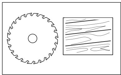
- Identify the correct saw blade to be used for the material to be cut.
- Use only saw blades that are marked with a speed equal or higher than the speed marked on the tool.
- Always wear a dust mask.
- Always wear safety glasses or eye shields when using the cutting-off machine Everyday eyeglasses have only impact-resistant lenses; they are NOT safety glasses. Following this rule will reduce the risk of serious personal injury.
- Always wear hearing protection during extended periods of operation. Following this rule will reduce the risk of serious personal injury.
- Keep your hands away from cutting area. Do not reach under the material being cut because the nearness of the blade to your hand is hidden from your sight.
- Do not use dull or damaged blades. Bent blades can break easily, or cause kickback.
- Always check walls, floors and ceilings to avoid hidden power cables and pipes.
- After long working period, external metal parts and accessories could be hot.
- Only withdraw the blade from the cut when the blade has been stopped moving.
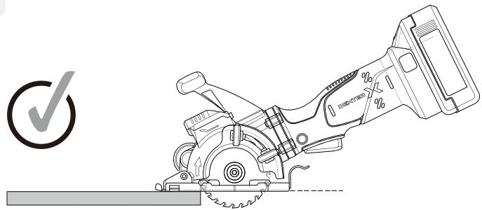
- The pivoting blade foot must be held firmly against the material being cut to reduce saw vibration, blade jumping and blade breakage.
- Before cutting, check the cutting line is free of nails, screws, etc.
- If possible, ensure the work-piece is firmly clamped to prevent movement.
- Never stop the cutting blade by applying side pressure to the blade.

WARNING: When not in use, place circular saw on a stable surface, shoe side down, where it will not cause a tripping or falling hazard.
Some tools with large battery packs will stand upright on the battery pack but may be easily knocked over.

WARNING: Some dust particles created by power sawing, contain chemicals known to cause cancer, birth defects or other reproductive harm.
Some examples of these chemicals are:
- Lead from lead-based paints.
- Crystalline silica from bricks and cement and other masonry products.
- Arsenic and chromium from chemically treated lumber.
Your risk from these exposures varies, depending upon how often you do this type of work. To reduce your exposure to these chemicals:
• Work in a well-ventilated area.
- Work with approved safety equipment, such as those dust masks that are specially designed to filter microscopic particles.

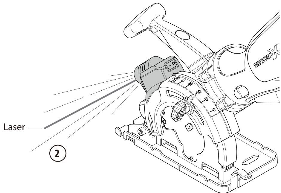
LASER BEAM
DO NOT STARE INTO BEAM
Laser Class 2
λ: 650 nm; P≤1mW
FN 60825-1:2014
SAFETY INSTRUCTIONS FOR LASER
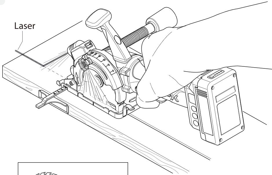
The laser guide used in the tool is Class II with maximum output 1mW and wavelength 650nm. The laser guide do not normally present an optical hazard, although staring at the beam may cause flash blindness.

CAUTION! The use of optical instruments with laser product will increase eye hazard.
- Do not stare your eyes to the laser beam.
- The laser shall be used and maintained in accordance with the manufacture's instruction.
- Never aim the beam at any person or an object other than the work piece.
• Always ensure the laser beam is aimed at a sturdy work piece without reflective surface. i.e. wood or rough coated surface are acceptable.
Bright shiny reflective sheet or the like is not suitable for laser use as the reflective surface could direct the beam back at the operator. - Do not change the laser light assembly with a different type. Any repairs must only be carried out by the laser manufacture or authorized service agent.
- Do not attempt to repairs the laser guide by yourself.
- Do not attempt to change any parts of the laser guide.
• Always switch off the laser when not used.
4. RESIDUAL RISKS
Even when the power tool is used as prescribed it is not possible to eliminate all residual risk factors. The following hazards may arise in connection with the power tool's construction and design :
- Damage to lungs if an effective dust mask is not worn.
- Damage to hearing if effective hearing protection is not worn.
- Damage to health resulting from vibration emission if the power tool is being used over a longer period of time or not adequately managed and properly maintained.
5. RISK REDUCTION
It has been reported that vibrations from handheld tools may contribute to a condition called Raynaud's Syndrome in certain individuals. Symptoms may include tingling, numbness and blanching, usually of the fingers, usually apparent upon exposure to cold. Hereditary factors, exposure to cold and dampness, diet, smoking, and work practices are all thought to contribute to the development of these symptoms. There are measures that can be taken by the operator to possibly reduce the effects of vibration :
- Keep your body warm in cold weather. When operating the product, wear gloves to keep the hands and wrists warm. It is reported the cold weather is a major factor contributing to Raynaud's Syndrome.
- After each period of operation, exercise to increase blood circulation.
- Take frequent work breaks. Limit the amount of exposure per day.
If you experience any of the symptoms of this condition, immediately discontinue use and see your doctor about these symptoms.

WARNING: Injuries may be caused or aggravated by prolonged use of a tool. When using any tool for prolonged periods, ensure you take regular breaks.

WARNING: This machine produces an electromagnetic field during operation. This field may, under some circumstances, interfere with active 'pas or passive medical implants. To reduce the risk of serious or fatal injury, we recommend persons with medical implants to consult their medical specialist and the medical implant manufacturer before operating this machine.
6. SYMBOL EXPLANATIONS

Please read the instructions carefully before starting the product

The product complies with applicable european directive and an evaluation method of conformity for these directive was done

Wear safety glasses

Conformity marking that product comply with applicable Ukraine technical regulations

Wear ear protection

Wear dust mask

Universal : compatible only with Sterwins UP20, Lexman UP20, and Dexter UP20

Wear safety gloves

Direct current (DC)

Waste electrical products should not be disposed of with household waste. Please recycle where facilities exist. Check with your local authority or retailer advice

This danger notice warns of damage to the appliance or others properties, or may cause physical injuries
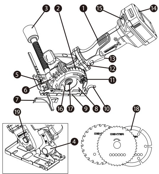
7. DESCRIPTION
This machine is designed for heavy duty uses. Please familiarize yourself with the major components of this tool before use.
text_image
Technical diagram of an engine cylinder assembly with numbered components and exploded view- Soft grip handle
- Fixed upper guard
- Vacuum adapter
- Dust extraction outlet
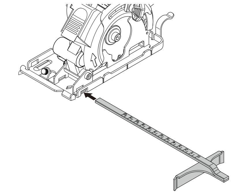
- Parallel guide clamping fixture
- Laser
- Parallel guide
- Power blade guard
- Base plate
- Lower guard lever
- Depth adjustment lever
- Lock off button
- ON/OFF switch
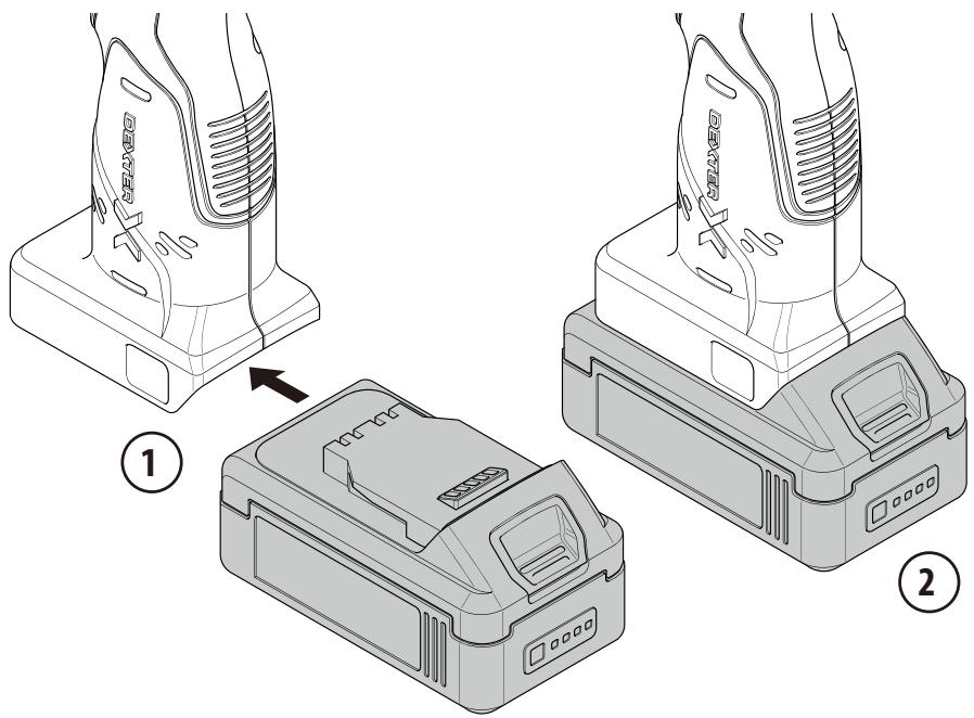
- Battery pack sold
- Battery pack release button
- Flange
- Saw blade pressing screw
- Saw blade
- Spindle lock button
8. TECHNICAL DATA
| MODEL | 20VMPS2-85.1 |
| RATEDVOLTAGE | 18 V |
| NO LOAD SPEED n0 | 2950/min |
| SPINDLE SIZE | 15 mm |
| BLADE SIZE | 85 mm |
| MAXIMUM CUTTING DEPTH | 27 mm |
| BARE MACHINE WEIGHT | 1.9kg |
| TCT BLADE | 85x1.6x 15mm |
| HSS BLADE | 85x1.2x 15mm |
| DIAMOND BLADE | 85x1.8x 15mm |
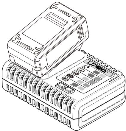
| COMPATIBILITIES WITH BATTERIES | 20V BA2-25.1 / 20V BA2-25.1XXX 2.5 Ah Li-ION battery pack20V BA2-50.1 / 20V BA2-50.1XXX 5.0 Ah Li-ION battery pack |
| COMPATIBILITIES WITH CHARGERS | Model no: 20V CH1-3A.1 / 20V CH1-3A.1XXX Input: 100-240 V~ 50-60 Hz, 75 W - Output: 21 V d.c. 3AModel no: 20V CH2-6A.1 / 20V CH2-6A.1XXX Input: 100-240 V~ 50-60 Hz, 150 W - Output : 21 V d.c. 6A |
| SOUND PRESSURE L_pA | In wood & concrete:96(dB)A In metal:99(dB)A |
| SOUND POWER L_wA | In wood & concrete:107(dB)A In metal:110(dB)A |
| UNCERTAINTY K_pA , K_wA | 3(dB) |
| VIBRATION TOTAL VALUE a_h (wood) | Main handle a_h=1,19m/s^2 / Auxiliary handle a_h=1,58m/s^2 |
| VIBRATION TOTAL VALUE a_h (metal) | Main handle a_h=1,79m/s^2 / Auxiliary handle a_h=2,09m/s^2 |
| UNCERTAINTY K_pA , K_wA | K=1,5m/s^2 |
- The declared total vibration value (s) and the declared emission value (s) sound have been measured in accordance with a standard test method and can be used to compare tools;
- The declared total vibration value (s) and the declared emission value (s) sound can also be used in a preliminary exposure assessment.
- Vibration emission and sound emission while using the power tool can be different from the declared values according to the ways of using the tool, in particular the type of workpiece; and
- It is necessary to identify the safety measures intended to protect the operator who are based on an estimate of exposure under actual conditions of use (in taking into account all parts of the maneuver cycle, such as the times when the tool is switched off and where it is running empty, in addition to the controller).
This tool may cause hand-arm vibration syndrome if its use is not adequately managed. Helping to minimize your vibration and noise exposure risk:
- Always use sharp chisels, drills and blades.
- Maintain this tool in accordance with these instructions and keep well lubricated (where appropriate).
- If the tool is to be used regularly then invest in anti vibration and noise accessories.
- Plan your work schedule to spread any high vibration tool use across a number of days.
It's recommended to wear ear protection during operation with this machine.
9. OPERATION

WARNING: Do not use power tools in explosive areas where flammable liquids, gases, dust are present. It creates sparks, which can lead to the ignition of dust, steam.

NOTE: Always lay the saw from the work before switching on or switch off.
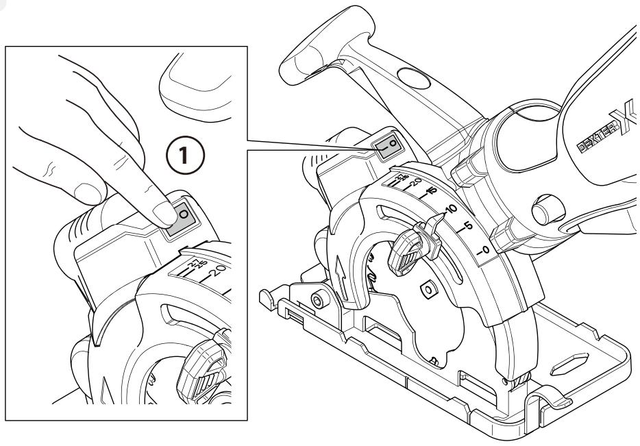
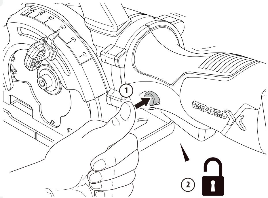
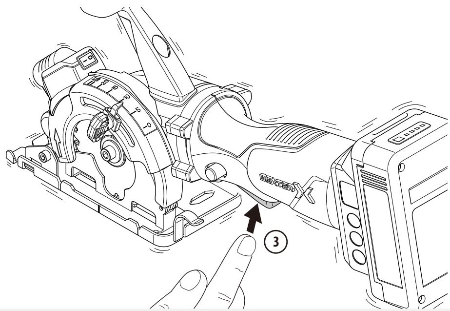
A. POWER SWITCH AND LOCK-OFF BUTTON
Your switch is locked off to prevent accidental starting. Depress lock off button then on/off switch and release lock off button. Your switch is now on. To switch off just release the on/off switch.
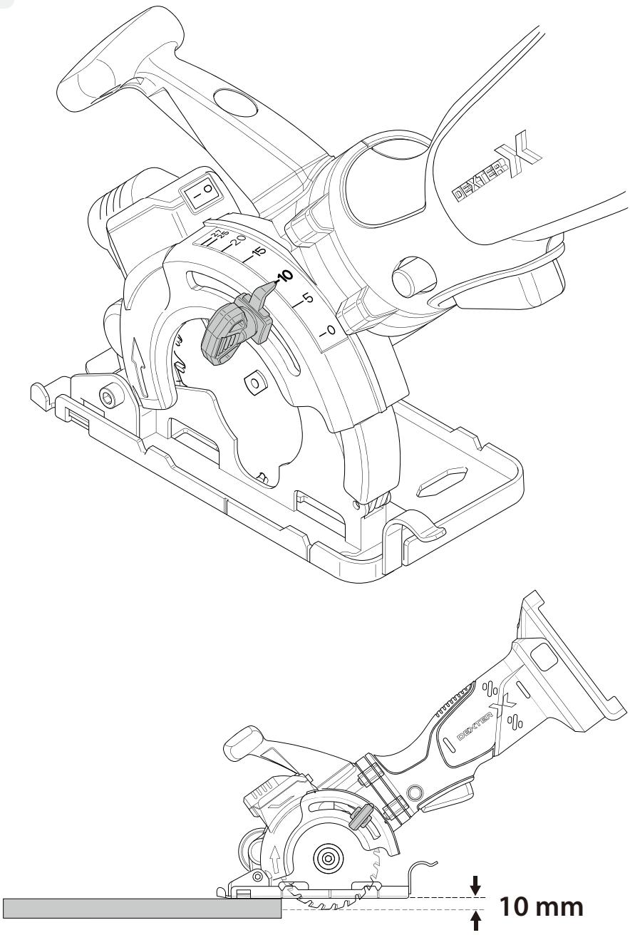
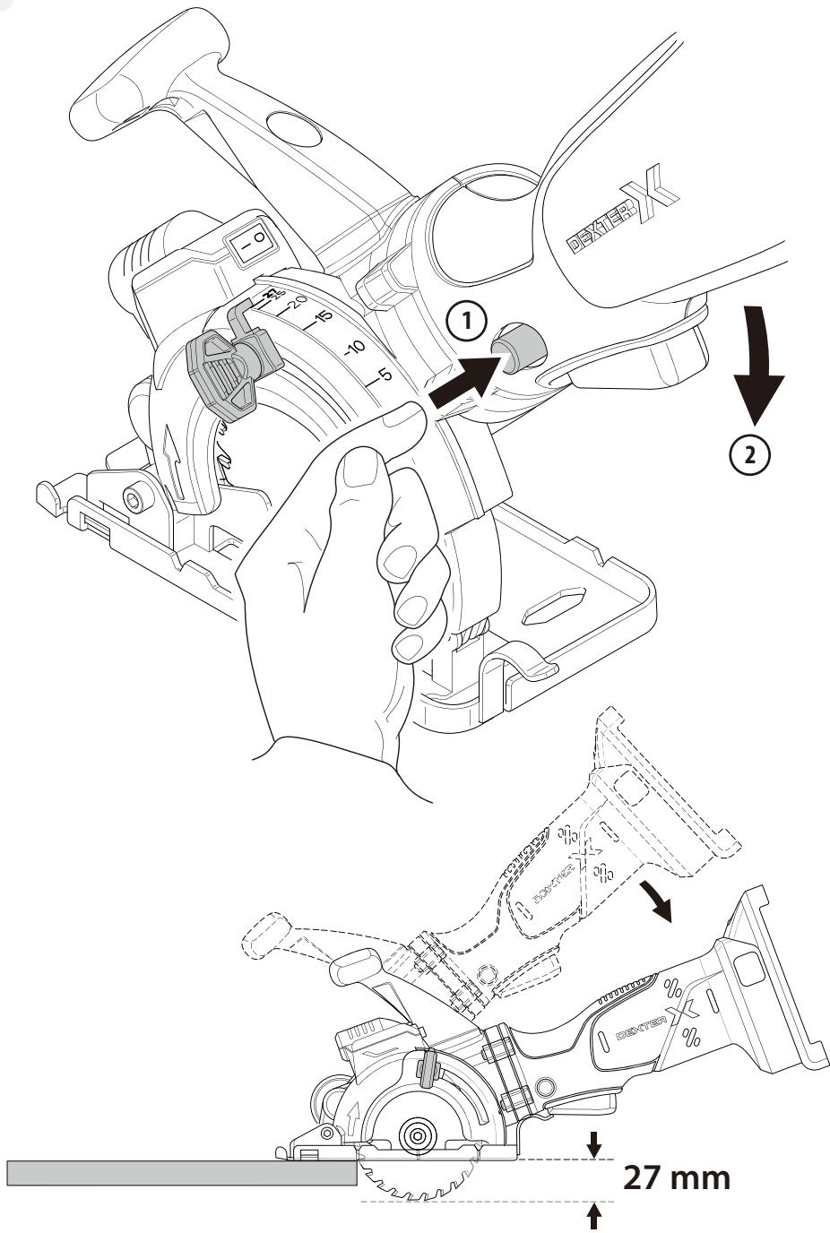
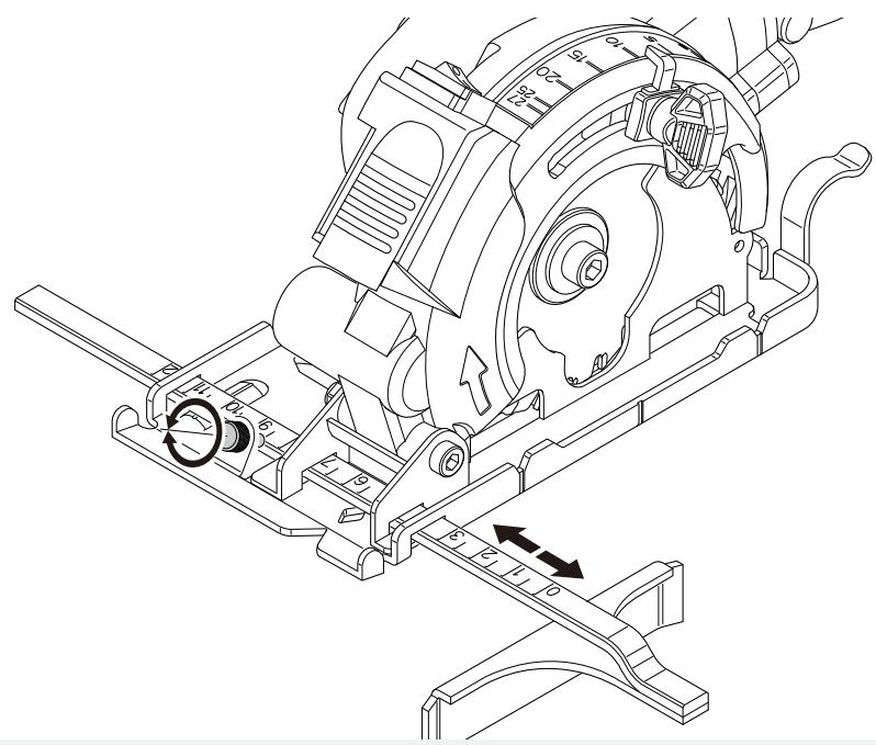
B. ADJUSTING THE CUTTING DEPTH
- Untight the depth adjustment lever.
- Manually push the lever at desired depth setting on the scale.
- Tight the depth Adjustment Lever at the desired setting.
| VALIDATED CUTTING DEPTH (MM) | |
| Wood | 27 mm |
| Aluminium | 3 mm |
| Polycarbonate plate | 16 mm |
| Tile | 9 mm |
| Galvanized steal sheet | 0,6 mm |

WARNING: Always take in consideration the suggested blade depth setting.
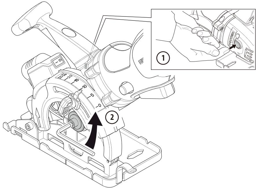
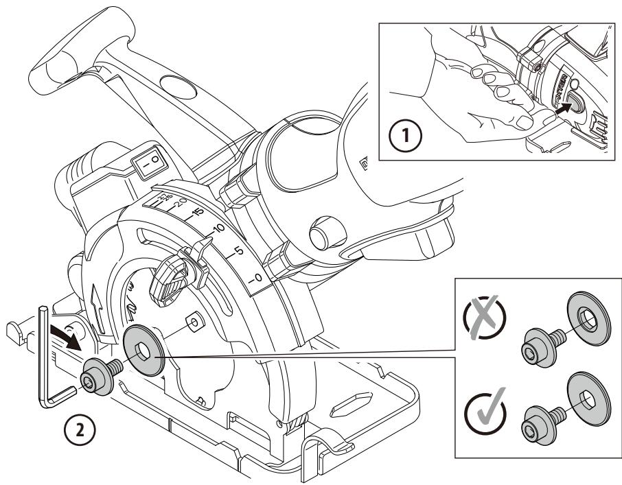
C. CHANGING THE SAW BLADE

WARNING: To prevent personal injury, always remove the power source BEFORE assembling parts, making adjustments or changing blades.

WARNING: Be sure to wear protective work gloves while handling the saw blade. The blade can injure unprotected hands.

WARNING: Only use saw blades that correspond with the characteristic data given in this manuel.

WARNING: This blade will be extremely hot after use. Be sure to let the saw blade and cool before changing blades.
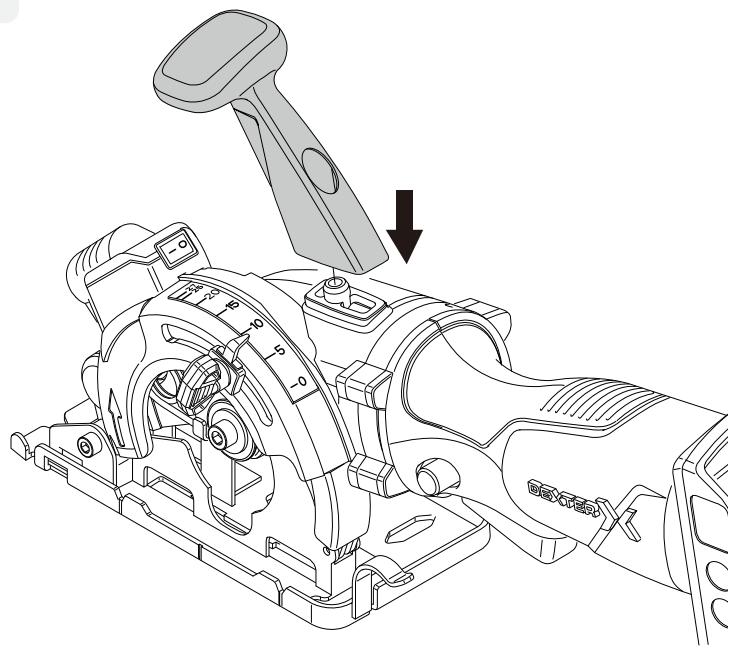
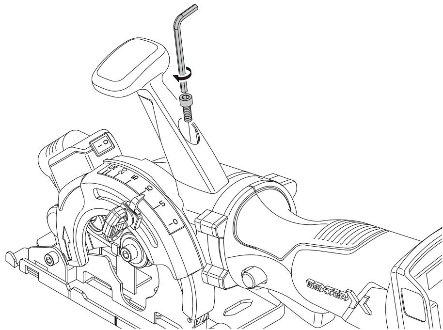
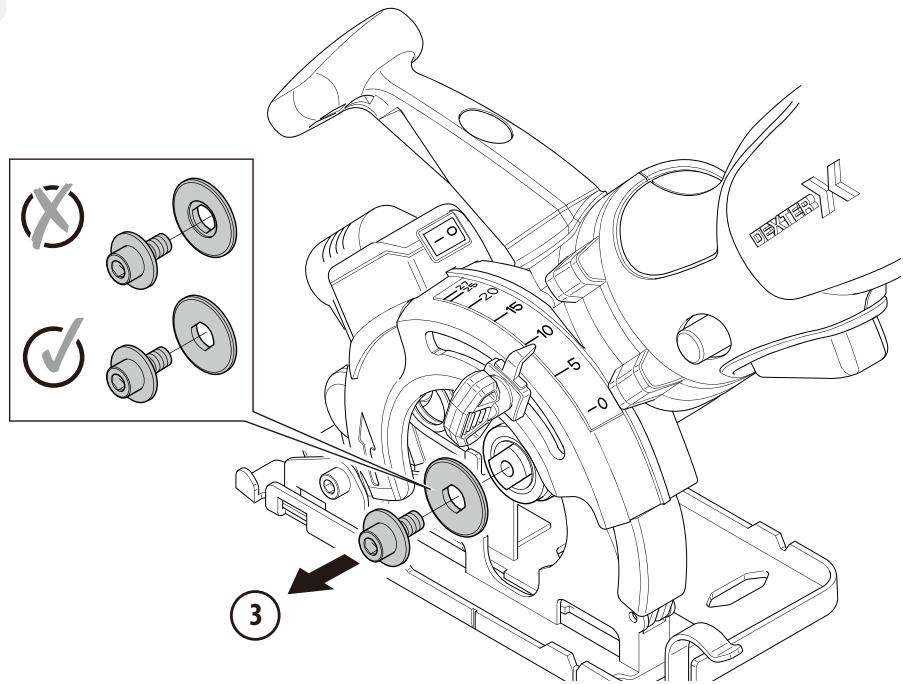
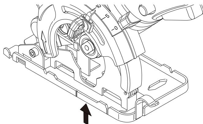
MOUNTING
Clean the saw blade and all the clamping parts. Check the new blade. Place the blade onto the spindle with the label facing outward. The hole in the blade should locate onto the spindle and fit firmly with the inner flange. Insert the outer flange over the spindle. Depress the spindle lock button. Tighten the lock bolt with the hex key. Check that the blade is securely fastened by continuing to hold down the spindle lock button and attempting to manually rotate the blade. If installed correctly, the blade should not spin.

WARNING: When mounting, ensure that the cutting direction of the teeth (direction of arrow on saw blade) is the same as the direction-of-rotation arrow above the upper blade guard match.

WARNING: Use a saw blade suited to the material and cut quality desired.
REMOVING
Press the spindle lock button and keep it depressed. Place the hex key into the lock bolt. Turn the hex key clockwise to loosen the lock bolt. Remove the outer flange. Grasp the blade with your gloved hand and remove the blade by the slot of the base plate.

WARNING: The spindle lock button may be actuated only when the saw blade is at a standstill.
D. SAWDUST EXTRACTION
Transportation of products can be operate with any kind of closed transport, the packaging of the manufacture or without it, but in this case, the product must be prevented from mechanical damage, precipitation, exposure to chemically active substances and compliance with precautionary measures for the transport of fragile goods.
E. TRANSPORTATION CONDITIONS
Your saw includes a vacuum adapter that attaches to the dust extraction outlet on the saw. This adapter port can be attached to a vacuum cleaner (sold separately). The use of the vacuum is strongly recommended as it keeps the work area clean, strongly increases cut visibility and reduces airborne dust. It also keeps dust out of the working elements of the guard.
10. MAINTENANCE

WARNING: Do not allow brake fluids, gasoline, petroleum-based products penetrating oils, etc... come In contact with plastic parts. They contain chemicals that can damage, weaken or destroy the housing, thus compromising the integrity of the double insulation.
A. GENERAL

WARNING: Always remove the battery pack from the tool before carrying out any adjustment, servicing or maintenance. Your power tool requires no additional lubrication or maintenance.
Never use water or chemical cleaners to clean your power tool. Wipe clean with a dry cloth. Always store your power tool in a dry place. Keep the motor ventilation slots clean. Keep all working controls free of dust. Occasionally you may see sparks through the ventilation slots. This is normal and will not damage your power tool.
Replace the saw blade according to which material to saw, as soon as proper and efficient sawing is therefore no longer possible. Clean the appliance after completing your sawing work. Remove any dirt (e.g saw dust).
The ambient temperature range for tool and battery use and storage is 0^ C to +45^ C.
The recommended ambient temperature range for the charging system during charging is 0^ C to +40^ C.
The relative humidity of the area must be not more than 80% without direct exposure to rain and excessive dust content of the air.
After use, please store the saw blade with anti-rust oil, and put all accessories back into the package to avoid loss. If the parts are lost, please contact the store for repairs before use.
There are some user serviceable parts in your power tool. Please refer to the spare part list of the manual.
B. INSPECTING THE MOUNTING SCREWS
Regularly inspect all mounting screws and ensure that they are properly tightened. Should any of the screws be loose, tighten them immediately. Failure to do so could result in serious injuries.
The motor unit winding is the very "heart" of the power tool. Exercise due care to ensure the winding does not become damaged and/or wet with oil or water.
11. TROUBLE SHOOTING
| PROBLEM | POSSIBLE CAUSE | SOLUTION |
| PRODUCT DOES NOT START | Not connected to power supply | Connect to power supply/Battery |
| Power battery is defective | Check by a specialist electrician | |
| Other electrical defect to the product | Check by a specialist electrician | |
| The battery is low power | Need to charge the battery pack before operating | |
| THE MACHINE STOPS WORKING AFTER ROTATING SLOWLY | The battery is low power | Need to charge the battery pack before operating |
| Air vents are blocked | Clean the air fans by blowing through the air vents | |
| SPARKING VISIBLE THROUGH THE HOUSING AIR VENTS | A small amount of sparking may be visible through the housing vents | This is normal and does not indicate a problem |
| UNSATISFACTORY RESULT | Saw blade is worn | Replace with new saw blade |
| LASER OR LED IS NOT WORKING | As the laser is supplied by the UP20 battery, the laser has been damaged. | Check by a specialist electrician |
12. PROTECT OUR ENVIRONMENT

CAUTION! This product has been marked with a symbol relating to removing electric and electronic waste. This means that this product shall not be discarded with household waste but that it shall be returned to a collection system which conforms to the European WEEE Directive. Contact your local authorities or stocks for advice on recycling. It will then be recycled or dismantled in order to reduce the impact on the environment. Electric and electronic equipment can be hazardous for the environment and for human health since they contain hazardous substances.
13. WARRANTY
Dexter products are designed to the highest DIY quality standards. Dexter provides a 36-month warranty for its products, from the date of purchase. This warranty applies to all material and manufacturing defects which may arise. No further claims are possible, of whatever nature, direct or indirect, relating to people and/or materials. Dexter products are not intended for professional use.
In the event of a problem or defect, you should first always consult your Dexter dealer. In most cases, the Dexter dealer will be able to solve the problem or correct the defect.
Repairs or the replacement of parts will not extend the original warranty period.
Defects which have arisen as a result of improper use or wear are not covered by the warranty. Amongst other things, this relates to switches, protective circuit switches and motors, in the event of wear.
Your claim upon the warranty can only be processed if:
- Proof of the purchase date can be provided in the form of a receipt.
- No repairs and/or replacements have been carried out by third parties.
- The issue is not a matter of normal wear and tear
- The tool has not been subjected to improper use (overloading of the machine or fitting non-approved accessories).
- The required maintenance and repair works have been performed correctly
- There has been no forcing, improper handling, unauthorised use, or accidents
- There is no damage caused by external influences or foreign bodies such as sand or stones.
- There is no damage caused by non-observance of the safety instructions and the instructions for use.
- There is no force majeure on our part.
- No incorrect parts have been used, parts not made by DEXTER, whereas they prove to be the cause of deterioration
- The tool / battery / charger have never been disassembled or opened
- The tool / battery / charger have been in a wet environment (dew, rain, submerged in water, ...)
- A description of the complaint is enclosed.
The warranty stipulations apply in combination with our terms of sale and delivery.
Faulty tools to be returned to Dexter via Dexter dealer will be collected by Dexter as long as the product is properly packaged. If faulty goods are sent directly to Dexter by the consumer, Dexter will only be able to process these goods if the consumer pays the shipping costs.
Products which are delivered in a poorly packaged condition will not be accepted by Dexter.
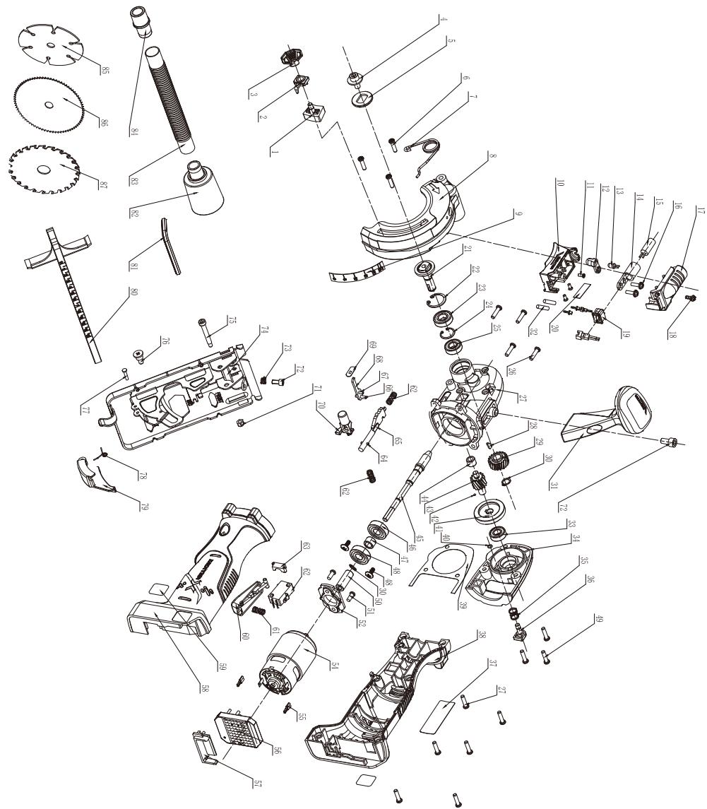
14. EXPLODED VIEW WITH PARTS LIST
text_image
Exploded view diagram of a mechanical assembly with numbered parts for identification- EXPLODED VIEW WITH PARTS LIST
| N° | PART NAME | Qty | N° | PART NAME | Qty |
| 1 | Depth adjustment screw | 1 | 44 | Needle Bearing | 1 |
| 2 | Depth indicator block | 1 | 45 | Connecting rod gear | 1 |
| 3 | Depth lock button | 1 | 46 | Bearing 609 | 2 |
| 4 | Saw blade pressing screw | 1 | 47 | Bearing 9X14X10 | 1 |
| 5 | Flange | 1 | 48 | Screw M4X8 | 2 |
| 6 | Screw M4×14 | 3 | 49 | TORX screw M4×14+spring washer 4 | 3 |
| 7 | spring | 1 | 50 | Connection sleeve | 1 |
| 8 | Head shell | 1 | 51 | Screw M4X8 | 2 |
| 9 | Depth label | 1 | 52 | Motor support | 1 |
| 10 | Laser seat | 1 | 53 | ||
| 11 | Screw M3X10 | 3 | 54 | Motor | 1 |
| 12 | lampshade | 1 | 55 | plugs 4.8 | 2 |
| 13 | Lamp bead | 1 | 56 | Controller | 1 |
| 14 | Laser bracket | 1 | 57 | Main engine connection bracket | 1 |
| 15 | Laser head | 1 | 58 | Left housing | 1 |
| 16 | Screw ST3.5X12 | 2 | 59 | UP20 label | 2 |
| 17 | Laser cover | 1 | 60 | Switch button | 1 |
| 18 | Screw ST2.9X10 | 1 | 61 | spring | 3 |
| 19 | Laser Switch | 1 | 62 | Micro switch | 1 |
| 20 | Laser label | 1 | 63 | Cable clamp | 1 |
| 21 | Output shaft | 1 | 64 | Pin 2.5X10 | 1 |
| 22 | circlip for hole22 | 1 | 65 | Switch self-locking push rod | 1 |
| 23 | Bearing 6900 | 1 | 66 | Pin 3X14 | 1 |
| 24 | circlip for hole | 1 | 67 | Pin 3.0X7.5 | 1 |
| 25 | Bearing 699-2RS | 1 | 68 | Block | 1 |
| 26 | TORX Screw ST4.2×16 | 10 | 69 | Dust pad | 1 |
| 27 | Gear box | 1 | 70 | Switch self-locking button | 1 |
| 28 | Key 2.5X3.7X10 | 1 | 71 | Nut M4 | 1 |
| 29 | Helical gear 20 | 1 | 72 | Screw M6*12 | 2 |
| 30 | circlip for shaft Φ9 | 2 | 73 | Spring | 1 |
| 31 | AUX handle | 1 | 74 | Baseplate assembly | 1 |
| 32 | Heat shrink tube | 2 | 75 | Screw M4 | 1 |
| 33 | Bearing 698-2Z | 1 | 76 | Screw | 1 |
| 34 | Gear box cover | 1 | 77 | Rivet | 1 |
| 35 | Spring | 1 | 78 | Torsion spring | 1 |
| 36 | Self-locking cap | 1 | 79 | Limit block | 1 |
| 37 | Label | 1 | 80 | Parallel guide | 1 |
| 38 | Right housing | 1 | 81 | Wrench 5# | 1 |
| 39 | Sealing Paper | 1 | 82 | Vacuum pipe connector D | 1 |
| 40 | Wire circlip | 1 | 83 | Corrugated pipe | 1 |
| 41 | Big arc bevel gear | 1 | 84 | Vacuum pipe connector B | 1 |
| 42 | Steel Ball Φ3 | 1 | 85 | Diamond saw blade | 1 |
| 43 | Gear shaft | 1 | 86 | HSS saw blade | 1 |
| 87 | TCT saw blade | 1 |

EU/EC Declaration of conformity Déclaration UE/CE de conformité DECLARACIÓN CE / UE DE CONFORMIDAD Declaração CE/UE de conformidade

natural_image
Pixelated illustration of a person holding a blue object (no text or symbols visible)EN|FR| ES|PT|
819934 - EAN Code: 3276007234343 Industrial Type Design Reference: 20VMPS2-85.1
DEXTER
SN SSSSSS XX DDMMYY nn PPPPPP (SN: Serial No., SSSSSS : Supplier code, XX : Factory ID, DDMMYY: Production date, nn: number of version of product, PPPPPP : Incremental number)
The object of the declaration described above is in conformity with the relevant Union harmonization legislation|L'objet de la déclaration décrit ci-dessus est conforme à la législation d'harmonisation de l'union applicable|El objeto de la declaración descrita anteriormente es conforme a la legislación de armonización pertinente de la Unión|O objeto da declaração acima descrita está en conformidade com a legislação de harmonização da União aplicável:|
2006_42_EC_MACHINE machinery|Machines|máquinas |máquinas|
2014_30_EU_EMC Electromagnetic compatibility|compatibilité électromagnétique|compatibilidad electromagnética |compatibilidade eletromagnética |
2011_65_EU_RoHS Restriction of hazardous substances in electrical products|Restriction des substances dangereuses dans les produits électriques|Restricción de sustancias peligrosas en equipos eléctricos.|Restrição de substâncias perigosas em equipamentos elétricos|
References to the relevant harmonised standards used or references to the specifications in relation to which conformity is declared|Références des normes harmonisées pertinentes appliquées ou des spécifications par rapport auxquelles la conformité est déclarée|Referencias a las normas armonizadas pertinentes utilizadas, o referencias a las especificaciones respecto a las cuales se declara la conformidad|Referências às normas harmonizadas pertinentes utilizadas ou referências às especificações para as quais a conformidade é declarada|
EN 62841-1:2015 EN 62841-2-5:2014 EN 60745-2-22:2011+A11:2013
EN IEC 55014-1:2021 EN IEC 55014-2:2021
RoHS Directive (EU)2015/863 amending Directive 2011/65/EU IEC 62321-2:2013 IEC 62321-1:2013 IEC 62321-3-1:2013 IEC 62321-5:2013 IEC 62321-4:2013+A1:2017 IEC 62321-7-1:2015 IEC 62321-7-2:2017 & ISO 17075-1:2017 IEC 62321-6:2015 IEC 62321-8:2017 EN IEC 63000:2018
When applicable, the name and number of notified body number[Le cas échéant, le nom et le numérp de l'organisme notifié]Cuando corresponda * el nombre y número de laboratorio notificado que haya emitido la certificación y la referencia al documento]Quando aplicável * o nome e número do laboratório notificado que emitiu a certificação e a referência ao documento]
Signed for and on behalf of|Signé par et au nom de|Firmado por y en nombre de|Assinado por e em nome de:|
Place and date of issue|Date et lieu d'établissement|Lugar y fecha de expedición|Local e data de emissão|
Eric LEMOINE International Project Quality Leader
Ronchin
28/02/2022


DICHIARAZIONE DI CONFORMITÀ CE / UE DEKLARACJA ZGODNOŚCI WE / UE ΔΗΛΩΣΗ ΣΥΜΜΟΡΦΩΣΗΣ ΕΚ / EE DECLARAΤΙΑ CE / UE DE CONFORMITATE
Modello di prodotto/prodotto|Model produktu/produkt|Μοντέλο προϊόντος/Προϊόν:|Modelul de produs/produsul:]
819934

natural_image
Pixelated illustration of a person holding a blue object (no text or symbols visible)IT|PO| GR|RO|
La presente dichiarazione di conformità è rilasciata sotto la responsabilità esclusiva del fabbricante|Niniejsza deklaracja zgodności wydana zostaje na wyłączną odpowiedzialność producenta.|Επωνυμία και διεύθυνση του κατασκευαστή ή του εξουσιοδοτημένου ανιπτροσώπου του|Denumirea și adresa producátorului sau a reprezentantului său autorizat:
ADEO Services, 135 Rue Sadi Carnot - CS 00001 59790 RONCHIN - France
La presente dichiarazione di conformità è rilasciata sotto la responsabilità esclusiva del fabbricante|Niniejsza deklaracja zgodności wydana zostaje na wylączną odpowiedzialność producenta.|H παρούσα δήλωση συμμόρφωσης εκδίδεται με αποκλειστική ευθύνη του κατασκευαστή|Declaratia de conformitate este emisă pe răspunderea exclusivă a producătorului|
819934 - EAN Code: 3276007234343
Industrial Type Design Reference: 20VMPS2-85.1
DEXTER
SN SSSSSS XX DDMMYY nn PPPPPP (SN: Serial No., SSSSSS : Supplier code, XX : Factory ID, DDMMYY: Production date, nn: number of version of product, PPPPPP : Incremental number)
Riferimenti alle pertinenti norme armonizzate utilizzate o alle specifiche in relazione alle quali è dichiarata la conformità|Odwołania do odnośnych norm zharmonizowanych, które zastosowano, lub do specyfikacji, w odniesieniu do których deklarowana jest zgodność|Μνεία των σχετικών εναρμονισμένων προτύπων που χρησιμποιούνται ή μνεία των προδιαγραφών σε σχέση με τις οποίες δηλώνεται η συμμόρφωσή|Referintele standardelor armonize relevante folosite sau referintele specificaților în legătură cu care se declaraă conformitatea:
EN 62841-1:2015
EN 62841-2-5:2014
EN 60745-2-22:2011+A11:2013
EN IEC 55014-1:2021
EN IEC 55014-2:2021
RoHS Directive (EU)2015/863 amending Directive 2011/65/EU
IEC 62321-2:2013
IEC 62321-1:2013
IEC 62321-3-1:2013
IEC 62321-5:2013
IEC 62321-4:2013+A1:2017
IEC 62321-7-1:2015
IEC 62321-7-2:2017 & ISO 17075-1:2017
IEC 62321-6:2015
IEC 62321-8:2017
EN IEC 63000:2018
Dove applicabile * il nome e il numero del laboratorio notificato che ha rilasciato la certificazione e il riferimento al documento|W stosownych przypadkach * notyfikowana nazwa i numer laboratorium, które wydało certyfikat oraz odniesienie do dokumentu|Otou iαχεί» το γνωστοποιημένο όνομα και τον αριθό του εργαστηρίου του εξέδωσε την πιστοποίηση και την αναφορά στο έγραφο|Unde este cazul * numele şi numárul de laborator notificate care a liberat certificarea și trimiterea la document|
International Project Quality Leader
Ronchin
28/02/2022

natural_image
Abstract pixelated pattern with no discernible text or symbols


natural_image
Illustration of a globe with multiple flagpoles and flags, no text or symbols presentS/N :

text_image
FR IT PAP CEFabriqué en Chine
** Garantie 3 ans / 3 años de garantía / Garantia de 3 anos / Garanzia 3 Anni / Εγγύηση 3 ετών / Gwarancja 3-letnia / Гарантия 3 года / Кепілдік 3 жыл / Гарантія 3 років / Garanție 3 ani / 3-year guarantee
ADEO Services - 135 Rue Sadi Carnot - CS 00001 59700 RONCHIN - France
Imported by Adeo South Africa (PTY) LTD T/A Leroy Merlin, Hosted in Leroy Merlin Fourways Store 35 Roos Street, Witkoppen Ext 97, Sandton, 2191 Johannesburg, Gauteng, South Africa
Tel: +27 10 493 8000 Email: contact@leroymerlin.co.za
CLASS 2 LASER PRODUCT
EN60825-1:2014
MAX OUTPUT ≤1MW λ=650NM
PT
RADIAÇÃO A LASER
USCITA MAX ≤ 1MW λ=650NM
RU
ЛАЗЕРНОЕ ИЗЛУЧЕНИЕ
m = 311
m = 311
m = 311
m = 311
m = 311
m = 311
m = 311